1
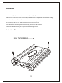
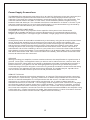
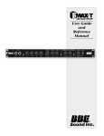
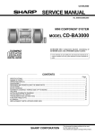
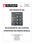
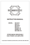
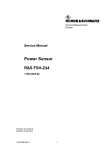
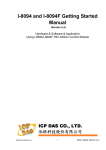
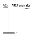
INSTRUCTION MANUAL
MODEL : BA3000.1D
MONO CHANNEL
HIGH POWER CAR AMPLIFIER
PLEASE READ THIS MANUAL BEFORE INSTALLATION AND USING AMPLIFIER
Congratulations on your purchase!
Your new high fidelity bridgeable/stereo amplifier is designed to deliver maximum enjoyment and one
year of trouble free service. Please take a few moments to read this manual thoroughly.
It will explain the features and operation of your unit and help insure trouble free installation.
Features
CLASS ''D''
- Fully 1 Ohm Stable Operation
- Military Spec Audiophile Grade Components
- High Efficiency PWM Power Supply
- Multi-stranded Power Torroid
- Two Torroidial Core
- MOSFET Transistors
- Over Sized Capacitor Banks
- Master / Slave Capability
- Discrete Mount Power & Speaker Terminals
- Varible Lowpass Electronic Crossover
- Varible Subsonic Filter
- 3way Protection Circuitry
- Soft Remote On/off Circuitry
- Digital Subwoofer Level Control
Precautions: Read First!
- If after reading the direction you feel uncomfortable about installing the amplifier in your car, or not
equipped or competent to do so, you should have the amplifier installed by an authorized installer.
It's your car!
- Negative battery terminal must be disconnected before any electrical connection are made.
- Be sure choose a location that provides substantial ventilation for the amplifier. The most preferred
locations would be in your car's trunk or on the back wall of a truck.
- The location chosen should provide at least 4" of clearance above the amplifier for adequate
ventilation.
- If the amplifier is to be mounted vertically be sure that it is in a place where adequate air will flow
along the length of its heatsink fins for cooling.
- NEVER mount the amplifier up side down, this will cause the heat to rise back into the amplifier
causing thermal shutdown or possible permanent damage.
- NEVER mount the amplifier in a location that is subject to direct sunlight or exposed to moisture.
1
Precautions: Read First!
- Be sure to mount the amplifier to a strong, solid surface which will not give way under the stress of a
sudden stop or accident.
- Make sure that the mounting screws will not penetrate the gas tank, brake and fuel lines, wiring or
other critical parts of your car when installed.
- NEVER operate the amplifier without the proper power and ground wire - 0 gauge minimum.
- NEVER operate the amplifier without proper fusing. Fuse holder must be located with in 18 inches
of the battery. This fuse is to protect the car, not the electronics. In case of a short, the fuse will
blow instead of the wire burning up. Using other than the recommended fuse ratings at the battery
and at the amplifier may cause damage to the amplifier and will void your warranty.
- Do not run wiring underneath or outside the car since exposure to the elements may cause the
insulation to deteriorate rapidly, resulting in short-circuits and/or intermittent operation.
All cables should be run beneath carpets and inside trim pieces.
- To help minimize interference, it is best to run the power cables along the opposite side from the
audio cables.
- Whenever wires pass through metal, rubber or plastic grommets must be used to prevent the metal
from wearing through the installation and causing a short.
- Whenever possible, use cable ties, mounting clamps and similar wiring aids. Adding stress relief
loops to wiring is also advisable to prevent straining or breakage.
- It is best to test the system before the amplifier is mounted and interior of car is reassembled.
- If the temperature inside your car reaches extreme levels(such as sitting locked up for several hours
in the hot sun or exposed to a very cold winter's day), the amplifier may go into protection mode and
shut off. Leave the unit off until the ambient temperature returns to normal.
- The amplifier operates with any vehicle using a 12 volt negative ground system. If you are not sure of
the type of electrical system in your vehicle, consult your authorized dealer or qualified mechanic.
- NEVER ground the speaker leads and NEVER allow the speaker leads to come in contact with each
other. Speaker wire should be 10 gauge minimum.
- Remote turn on wire must be switched by the radio or accessory circuit.
- Do not listen to high volumes for extended periods of time or hearing damage may occur.
CONTINOUS EXPOSURE TO SOUND PRESSURE LEVELS OVER 100dB MAY
CAUSE PERMANENT HEARING LOSS. HIGH POWERED AUTOSOUND SYSTEM
MAY PRODUCE SOUND PRESSURE LEVELS WELL OVER 130dB. USE
COMMON SENSE AND PRACTICE SAFE SOUND.
2
Installation
MOUNTING:
1. After reading the precautions, decide where you are going to install the unit.
2. Once the location has been determined, place the amplifier in position. Using a felt tip pen or pencil
mark the four holes to be drilled for mounting. NEVER use the amplifier as a template for drilling.
It is very easy to damage the amplifier surface in manner.
3. Drill four 1/8” diameter holes into mounting surface of steel panel. If you choose to mount on MDF
or wood panel, drill four 1/8” diameter holes into mounting surface.
4. It’s advisable to test the system before finally mounting of the amplifier.
5. Mount the amplifier using the supplied 4 self threading screws.
Installation Diagram
SELF TAP SCREWS
3
Power Supply Connections
The BA 3000 .1D is designed to work within 10 to 16 volts DC. Before any wires are connected, the
vehicle's electrical system should be checked for correct voltage supply with the help of a
voltmeter. First check the voltage at the battery terminals with the ignition in the off position. The
voltmeter should read no less than 12 volts. Next, check the battery with the engine running
between 1500 and 2000 rpm. The voltmeter should now read between 13.5 and 14.5 volts. If your
vehicle's electrical supply is not up to these specifications, we recommend having it checked by
an automotive mechanic before you continue the installation.
RECOMMENDED POWER WIRE
The proper wire size is very important for an amplifier of this power level. Because the
BA 3000 .1D is capable of drawing in excess of 90 amperes, we recommend 0 g auge wire for
lengths up to twenty feet. If a longer length is needed, a larger gauge wire may be necessary.
POWER
All amplifiers power wire should be wired directly to the battery using the wire requirements listed
above. Start at the amplifier and run the power wire through the vehicle to the battery. We
recommend the use of grommets when passing the power wire through any metal surface. Avoid
sharp corners or sharp body parts that may easily cut through the insulation on the wire. Avoid
running the power wire over engine components and near heater cores. Use an inline fuse to
eliminate the risk of a fire caused by a short in your power wire. Connect the fuse holder as close
to the battery positive as possible. For most applications, an 80 ampere Maxi fuse or comparable
ANL wafer fuse can be used. Now connect the wire to the battery, but remember to leave the fuse
out until all other wires are connected.
GROUND
When grounding your amplifier, locate a metal area close to the amplifier that is a good source of
ground. Once again, investigate the area you wish to use for electrical wires, vacuum lines, and
brake or fuel lines. Using either a wire brush or sandpaper, eliminate unwanted paint to supply a
better contact for your ground. Use the same g auge wire for ground as you did for the power.
Terminate the ground wire using the correct size ring terminal and attach it to the bare metal using
a nut and bolt. It is important for this connection to be solid. To complete the job, spread silicon
over the screw and bare metal to prevent rust and possible water leaks.
REMOTE TURN-ON
In between the power and ground is a remote turn-on terminal. This terminal must be connected
to a switched + 12volt source. Typically, remote turn-on leads are provided at the source unit that
will turn on and off the amplifier in correspondence with the source. If a radio does not have a
remote turn-on, then a power antenna wire may be used. Yet, if neither of these leads are
available at the source, a switched + 12 volt supply must be supplied. Run a minimum of 18-gauge
wire from the amplifier location to the source of the switched + 12 volt lead. If possible, route this
wire on the same side of the vehicle as your power wire. Connect the source remote output to the
wire, back at the amplifier, loosen the set screw for the terminal marked REM on the amplifier using
a 3mm Allen key. Cut the remote wire to length. Strip approximately 1/2 inch of insulation from the
end of the wire and insert into the terminal. Tighten the screw securely.
4
Power Supply Connections
The BA3000.1D offers not only the primary power terminal connections, but a secondary terminal which
will provide maximum power distribution capability. Whether you choose to daisy-chain your amplifiers
in a Master / Slave configuration, or simply want to pass power onto a full-range amplifier, you can do
so easily with the 0ga “positive” and “ground” terminals that run in parallel with the primary terminal. And
if you so desire, we highly endorse using these terminals to connect a power capacitor for maximum
power delivery from your amplifier, as shown below. We recommend a 1 farad cap as the minimum.
GND
B+
+
-
+
-
B+
REM
GND
ON
PROTECTION
SPEAKER OUTPUT
POWER
POWER
Power Capacitor
CAUTION!!! - please be sure to charge your capacitor as per manufacturers instructions, BEFORE,
connecting to the ampifier.
5
Single Amplifier Preamp Configuration
Connecting this amplifier to your head unit is really no different than typically done. It is equally important
to use a high quality RCA cable, as well as routing the cable on the opposite side of the power cable. And
proper level matching is of utmost importance, so not to overdrive your ampifier and subwoofers into high
levels of distortion and/or clipping (see Amplifier Control and Adjustments).
SUBSONIC
LINE INPUT
GAIN
BASS
FILTER
L.P.F
PHASE
REMOCON
MASTER
SLAVER
SLAVE
L
6V 0.24V
15Hz
50Hz
0dB
12dB
50Hz
250Hz
0°
180°
R
+12V REM GND
CH1
CAR STEREO HEAD UNIT
6
CH2
Master / Slave Preamp Configuration
The BA3000.1D is capable of running in a Master / Slave configuration. This means that two amplifers
can be ran in sync to the same subwoofer voice coil. The result of which is higher power output than
what one ampifier is capable of on the same load. Please be aware that each amplifier will see half the
impedance of your subwoofer (seeSpeaker Configuration). When an ampifier is ran in Slave mode, all
adjustments and input jacks are bypassed. The Master amplifier will dictate what is played by the Slave
unit. Simply using a single RCA cable and switching to Slave mode will run the secondary ampilfier
in this mode.
SUBSONIC
LINE INPUT
GAIN
BASS
FILTER
L.P.F
PHASE
REMOCON
MASTER
SLAVER
L
6V 0.24V
15Hz
50Hz
0dB
12dB
50Hz
250Hz
0°
180°
R
+12V REM GND
CH1
CAR STEREO HEAD UNIT
Slave Amplifier
7
CH2
SLAVE
Speaker Wiring Configuration
The BA3000.1D is a SINGLE CHANNEL dedicated subwoofer amplifier. Unlike other amplifiers, the
BA3000.1D operates as a single channel and cannot be bridged. Don't be fooled by the outputs. Two
outputs are used strictly for convenience and are parallelled internally on the amplifier. This means that
if both outputs are used with one driver each, the amplifier sees the same load as if the two same drivers
are connected to only one output terminal. In both diagrams, the amplifier sees a 2 Ohm load.
Wiring Diagram
In both diagrams, the amplifier sees a 2 ohm load.
GND
B+
+
+
-
B+
-
REM
GND
ON
PROTECTION
SPEAKER OUTPUT
POWER
POWER
4 ohms
4 ohms
GND
B+
+
+
-
B+
-
REM
GND
ON
PROTECTION
SPEAKER OUTPUT
POWER
POWER
4 ohms
4 ohms
Master / Slave Wiring Diagram
In this diagram, each amplifier sees a 2 ohm load.
GND
B+
+
-
+
-
B+
REM
GND
ON
PROTECTION
SPEAKER OUTPUT
POWER
4 ohms
POWER
GND
B+
+
-
+
-
B+
REM
GND
ON
PROTECTION
SPEAKER OUTPUT
POWER
POWER
8
Amplifier Control and Adjustments
The sensitivity adjustment is designed to provide proper level matching with various brands of
head units. It allows input signal to vary between 240 millivolts to 6 volts from the head unit or
any other signal processor. Begin by setting the sensitivity adjustment to the "MIN" (6 volts).
Using a compact disc that you are familiar with ,turn on head unit to the 3/4 volume setting.
Slowly turn up sensitivity adjustment towards the "MAX" (240 millivolts) using a flat head
screw driver. Stop turning on the onset of distortion and turn back just a slight. The 3/4 volume
setting is now the "maximum" volume for the head unit. The goal is to keep the level control to
the lowest setting yet still have enough signal to drive the amplifier. This is done to prevent overdriving the amplifier and to keep system noise to a minimum. It is important not over drive
speakers (at point of distortion) this will cause permanent damage to the speakers. Also, if the
amplifier itself is over driven, it could be damaged.
1
2
LINE INPUT
GAIN
3
4
5
6
7
BASS
L.P.F
PHASE
REMOCON
8
9
SUBSONIC
FILTER
MASTER
SLAVER
SLAVE
L
6V 0.24V
15Hz
50Hz
0dB
12dB
50Hz
250Hz
0°
180°
R
1. RCA Input Jack
4. Subsonic Filter
7. Remote Control Jack
2. Input Level Control
5. Bass Boost Control
8. Master/Slave Switch
3. Low Pass Frequency
6. Phase Control
9. Slave Input Jack
1. RCA Input Jacks - Low level, high impedance inputs. Use high quality RCA cables designed for mobile
applications.
2. Input Level Control - Level match the input in accordance to your source unit. Turn clockwise to
increase the level, counter clockwise to decrease. Amplifiers will run cooler and produce less system
noise at lower level settings.
3. Low Pass Frequency - Adjust the crossover frequency by turning clockwise to set to a higher frequency,
counter clockwise to set to a lower frequency.
4. Subsonic Filter Frequency - Adjust the subsonic filter frequency by turning clockwise to set to a higher
frequency, counter clockwise to set to a lower frequency.
5. Bass Boost - Adjustment between 0-12dB Gain at 45Hz for extra bass punch.
6. Phase Control - Adjust the relative phase of the output a range of 0-180 degrees for solid bass
response and accurate imaging.
7. Remote Control Jack - Used to connect remote bass level control module to the amplifier.
8. Master/Slave Switch - Select the remote level control or the on-board level control as the master
control.
9. Slave Input Jack - Used to connect to another amplifier when bridging 2 amps together. The Slave
mode bypasses normal input jacks and controls.
9
Troubleshooting the system
We have put together this trouble-shooting guide if you experience problems after
installing the amplifier. Please keep in mind that the majority of problems incurred are
caused by improper installation and not the equipment itself. In addition, there are many
components in the system that could cause various signal problems such as inducted
electrical noise and engine noise.
Before you can properly address the problem, you must first find the component that is
causing the problem. This will take patience and a process of elimination.
Symptom
Solution
No Output
Blown fuse
Bad RCA Cable(s)
+12V at power terminal
+12V at remote terminal
Grounding point clean and tight
Head Unit's fader not in center position
Replace
Replace
Check connection
Check connection
Check for ground w/meter
Set to center position
Low Output
Check level adjustments
Bad RCA cable(s)
Improper level matching
Re-adjust
Replace
Re-adjust
Engine Noise
Grounding points are clean and tight
Ground all components at same point
Try different grounding point
Bad RCA cable(s)
Use High Quality shielded RCA cables
Low Vehicle charging system and/or battery
Check for ground w/meter
Ground at same point
Change for better ground
Replace
Rejects inducted noise
Fix and/or replace
Red Protection L.E.D. Illuminated
Speaker short
Check speakers connection
for short circuit
Make sure speaker wires
do not touch chassis ground
Check speaker impedance
(Min 2 ohm Stereo, 4 Mono)
Check mounting location
for Adequate air Circulation
Speaker impedance too low
Speaker grounding out
Impedance too low
Overheating
10
Specification
4 OHMS @
1% THD
(10Hz - 250Hz)
1200W x 1
2 OHMS @
1% THD
(10Hz - 250Hz)
2000W x 1
1 OHMS @
1% THD
(10Hz - 250Hz)
3200W x 1
LOW PASS
FILTER
50Hz-250Hz @ 24dB
(VARIABLE)
PHASE
CONTROL
0~180 degrees
(VARIABLE)
SUBSONIC
FILTER
15Hz-45Hz @ 24dB
(VARIABLE)
FREQUENCY
RESPONSE
(-1dB)
10Hz-250Hz
SIGNAL TO
NOISE RATIO
(`A' WTD)
>100dB
INPUT
SENSITIVITY
240mV - 6V
INPUT
IMPEDANCE
22k Ohms
FUSE RATING
N/A - minimum 80 amp
is recommended
DIMENSIONS
(W x H x D)
13”x2.5”x26”
330x63x660mm
NOTE : Specifications & design subject to change without notice for improvements. Tested at
14.4v DC.
11