1
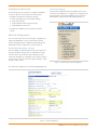
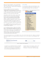
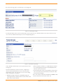
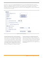
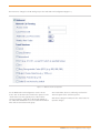
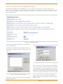
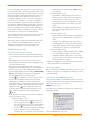
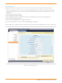
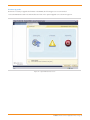
Application Note
ST-10010
October 25, 2007
IP8000 Conference Phone Configuration Guide
This application note provides the details on adding the IP8000 conference phone to the ShoreTel IP
phone system. This information applies to ShoreTel Release 6.1, 7.0 and 7.5.
Table of Contents
Overview
1
Switch Settings - Trunk Group
4
Requirements
1
ShoreTel System Settings - Individual Trunks
9
ShoreTel Requirements
1
IP8000 Configuration
10
Configuration Overview
2
Initial Configuration
ShoreTel Configuration
2
Retrieving IP Address ShoreTel System Settings - General
2
Connecting to the IP8000 Web Interface
10
Call Control Settings
2
General Configuration
12
Sites Settings
3
SIP Configuration
13
4
Firmware Upgrades
14
ShoreTel System Settings - Allocating Ports for
SIP Trunks
Overview
This document describes how to integrate the IP8000
conference phone into the ShoreTel IP Phone System.
Note: This information pertains to ShoreTel releases 6.1,
7.0 and 7.5 which will allow the conference phone to
connect by way of “SIP trunks”. This means that not all call
features are available to the conference phone. However,
the features required for everyday conference room use are
supported including the ability to make and receive calls,
basic call transfer, initiate a 3 party conference call as well
as be a participant in a 6 party conference call.
Requirements
The following requirements are necessary to integrate a
IP8000 conference phone to the ShoreTel IP Phone system
as described in this Application Note.
10
ShoreTel Requirements
• ShoreWare Server Software, ShoreTel 6.1 or higher.
The following build numbers are required:
- ShoreTel 6.1 : Build 11.15.3203.0 or higher
- ShoreTel 7.0 : Build 12.5.8101.0 or higher
- ShoreTel 7.5 : Build 12.12.6113.0 or higher
Versions prior to this release will not support the IP8000
conference phone
• ShoreTel SIP Trunk licenses are required
• A total of 2 SIP trunk licenses is strongly recommended.
This will support Call Transfers. A single SIP trunk license
will only support basic inbound and outbound calls.
Note: To optimize performance of the IP8000 conference
phone, be sure to consult Application Note ST-10026
“ShorePhone IP8000 Conference Phone: Best Practices”
10
Configuration Overview
Call Control Settings
The following steps are required to configure the IP8000
conference phone to work with the ShoreTel system:
1.Configure General ShoreTel system settings
The Call Control Options within ShoreWare Director may
need to be reconfigured. To configure these settings for the
ShoreTel system, log into ShoreWare Director and select
Administration, Call Control and then Options (Figure 1).
a. Call Control Options, Site and Switch settings
b. Setup Trunk Groups
c. Setup Individual Trunks and User Groups
d. Setup Off system extensions
2.Configure the IP8000 to function with the ShoreTel
system
ShoreTel Configuration
This section describes the ShoreTel system configuration to
support the IP8000.The section is divided into general
system settings and trunk configurations (both group and
individual) needed to support the conference phone.
ShoreTel System Settings - General
The first settings to address within the ShoreTel system are
the general system settings. These configurations include
the call control, the site and the switch settings. If these
items have already been configured on the system, skip this
section and go on to the “ShoreTel System Settings – Trunk
Groups” section below.
Figure 1 – Administration Call Control/Options
The “Call Control / Options” screen will then appear (Figure 2).
Figure 2 – Call Control/Options
IP8000 Conference Phone Application Note—Page 2
Within the “Call Control Options” screen confirm that the
appropriate settings are made for the “Enable SIP Session
Timer”, “Intra-Site Calls”, “Inter-Site Calls” and “Always Use
Port 5004 for RTP” fields.
Sites Settings
The next settings to address are the administration of sites.
These settings are modified under the ShoreWare Director
by selecting “Administration” then “Sites” (Figure 3).
Ensure the “Enable SIP Session Timer” parameter is
enabled. Next the Session Interval Timer needs to be
configured. The recommended setting for “Session Interval”
is 1800 seconds. The “Refresher” field needs to be configured for “Caller (UAC)” [User Agent Client] This allows the
IP8000 to be in control of the session timer refresh.
Verify that the “Intra-Site Calls” and the “Inter-Site Calls”
parameters under the” Voice Encoding and Quality of
Service” section are configured for the proper CODEC
desired. For the Intra-Site Calls verify the desired audio
CODEC is configured for calls within the system, this is
typically configured for 64 Kbps (G.711) and is recommended for use with the IP8000. The settings should then be
confirmed for the desired audio CODEC for Inter-Site calls
(calls between sites), typically configured for 8 Kbps (G.729).
Note: The IP8000 conference phone uses both G.711 and
G.729 CODECs. The CODEC setting will be negotiated to
the highest CODEC supported.
You must disable the parameter “Always Use Port 5004 for
RTP”, it is required for implementing SIP on the ShoreTel
system. For SIP configurations, Dynamic UDP must be used
for RTP Traffic. Note: If the box is unchecked MGCP will no
longer use UDP port 5004; MGCP and SIP traffic will use
dynamic UDP ports. It is also important to note that this
“one time” setting requires a system restart (IP phones,
ShoreGear switches & servers) to take effect.
Figure 3 – Administration/Sites
This selection brings up the “Sites” screen. Within the “Sites” screen select the name of the site to configure. The “Edit Site”
screen will then appear. The only change required to the “Edit Site” screen is to the “Admission Control Bandwidth” field
(Figure 4).
Figure 4 – Admission Control Bandwidth
The Admission Control Bandwidth defines the bandwidth
available to and from the site. This is important as SIP
devices may be counted against the site bandwidth. See
the ShoreTel Planning and Installation Guide for more
information. When a call is “Intra-site” it will not count
against the “Admission Control Bandwidth” unless
“Teleworker” is checked in the “Trunk Group Page”.
IP8000 Conference Phone Application Note—Page 3
Switch Settings - Allocating Ports for SIP Trunks
The final general settings to configure are the ShoreGear
switch settings. These changes are modified by selecting
“Administration” then “Switches” in ShoreWare Director
(Figure 5).
Each Check box designated as a SIP trunk enables support
for 5 individual trunks.
ShoreTel System Settings - Trunk Group
ShoreTel Trunk Groups support both Dynamic and Static SIP
end point Individual Trunks.
Note: A ShoreGear switch can only support one Trunk
Group with Dynamic IP addressing.
The settings for Trunk Groups are changed by selecting
“Administration” then “Trunks” followed by “Trunk Groups”
within ShoreWare Director (Figure 7).
Figure 5 – Administration/Switches
This action brings up the “Switches” screen. From the
“Switches” screen simply select the name of the switch to
configure. The “Edit ShoreGear …Switch” screen will be
displayed. Within the “Edit ShoreGear …Switch” screen
select the desired number of SIP trunks from the ports
available (Figure 6).
Figure 7 – Administration /Trunk Groups
Figure 6 – ShoreGear Switch Setting
IP8000 Conference Phone Application Note—Page 4
This selection brings up the “Trunk Groups” screen (Figure 8).
Figure 8 – Trunk Groups Settings
From the pull down menus on the “Trunk Groups” screen select the “site” desired and then select “SIP” and click on the
“Go” link. The “Edit SIP Trunk Group” screen” will appear (Figure 9).
Figure 9 – SIP Trunk Group Settings
In the “Edit SIP Trunks Group” screen, input a name for the
trunk group.
Determine whether the trunks need to be configured as
inter-site trunks (trunks between sites) or intra-site trunks
(trunks within a site). The next step is to choose the setting
of the “Teleworkers” check box.
• By NOT checking Teleworker no bandwidth usage will
count against the site and the Intra-Site codec will be used
when calls are made Intra-Site.
• If the Teleworker checkbox “is” enabled then the call will
be counted against the allocation of bandwidth and the
Inter-Site codec will be used.
• Should Teleworker not be checked and the call goes from
San Jose (location of the SIP Trunk) to another site in NY
then Inter-Site will apply.
Note: The location of the SIP Trunk NOT the IP8000 is what
is used to determine the location of the call.
IP8000 Conference Phone Application Note—Page 5
The next item on this screen is the “Enable Digest Authentication” field. This is a SIP feature that allows a user ID and
password to be established for authentication. If this feature is configured for the Trunk Group the same settings must be
configured on the IP8000 although it is not necessary to enable this functionality for the IP8000 to operate properly.
The “Enable SIP Info for G.711 DTMF Signaling” box should not be enabled. Enabling SIP info is currently only used with SIP
tie trunks between ShoreTel systems.
Figure 10 – Inbound Trunk Settings
For the Inbound Trunk Settings, ensure the “Number of Digits from CO” matches your current extension length. It is
not necessary to select the “DNIS” (Dialed Number Identification Service) box to create a DNIS to extension mapping
or the “DID” (Direct Inward Dial) box to input a DID range.
You must enable the “Extension” parameter, this will allow
incoming calls to be directed to the extension dialed. It is
not necessary to utilize a “Translation Table”, unless you
plan on modifying the incoming digits. The last step for the
Inbound Trunk configuration is to enable the “Tandem
Trunking” parameter to allow trunking between trunk
groups. The “Destination:” should be configured for the
desired extension that a call should be routed in the event
that a user misdials a number, the example above (figure 10)
has an Auto Attendant configured. Trunk calls not routed by
previous entries under the Inbound Trunk routing will be
routed to the configured extension or as in Figure 10 to the
Auto Attendant.
IP8000 Conference Phone Application Note—Page 6
The next item to change for the SIP trunk groups is the outbound trunk configuration (Figure 11).
Figure 11 – Outbound Trunk Configuration
For the Outbound Trunk Configuration set the “Access
Code” and “Local Area Code” fields for the system. For the
“Trunk Services” boxes, typically none of these will be
selected, except for “Caller ID not blocked by default”, if
not enabled the IP8000 will not receive Caller ID information
when calls are sent via this trunk group.
Note: Remember, these are calls being sent from the
ShoreTel system to the conference phone.
After these settings are made press the “Save” button to
input the changes.
IP8000 Conference Phone Application Note—Page 7
The next item to change is under “Trunk Digit Manipulation” (Figure 12).
Typically when sending digits to the IP8000 phone it is not necessary to check the boxes for “Remove leading 1 from
1+10D”, “Remove leading 1 for Local Area Codes” and “Dial 7 digits for Local Area Code’ because only the extension digits
will be sent as this is an Off System Extension (OSE). No configuration is needed for the “Local Prefixes” parameter, or the
“Prepend Dial Out Prefix”.
Figure 12 – Trunk Digit Manipulation
Next configure an Off System Extension for each IP8000
phone you will deploy.
Selecting the “Edit” button for the Off System Extensions
will bring up the ”Off System Extension Ranges” dialog box
(Figure 13).
Figure 14 – Edit Range for Off System Extensions
Input a new range of off system extensions for the IP8000
phone and click “OK”. For this example the extension range
3000-3019 has been configured, although you only really
need one Off System Extension (OSE) defined, where First
and Last are the same number. This completes the settings
needed to set up the SIP Trunk Groups on the ShoreTel system.
Figure 13 – Off System Extension Ranges
Selecting the “New” button will bring up the “New Range”
dialog box (Figure 14).
Note: It is important to note that only one dynamic trunk
group can be set up per ShoreGear switch. If another
dynamic trunk group is desired another ShoreGear switch
will be needed.
IP8000 Conference Phone Application Note—Page 8
When it is desired to translate an off system extension to a
10 digit DID “Digit Translation” must be used. For example,
when a call is placed to an IP8000 phone by dialing ext.
3000 but the IP8000 device is configured with 4083313000
then Digit Translation needs to be used. The main reason for doing this is when it is necessary for calls made from the
IP8000 device to present a 10 digit number to the person
being called. It may also be needed for 911 related functionality.
ShoreTel System Settings - Individual Trunks
This section covers the configuration of the individual trunks.
Select “Administration” then “Trunks” followed by “Individual Trunks” to configure the individual trunks (Figure 15).
Figure 15 – Individual Trunks
The “Trunks by Group” screen, used to change the individual trunks settings, then appears (Figure 16).
Figure 16 – Trunks by Group
Select the site for the new individual trunk(s) to be added and select the appropriate trunk group from the pull down menu. In
this example the site is “HQ Sunnyvale Demo” and the trunk group is SIP – Dynamic x5450-5499”. Click on the ”Go” button to
bring up the “Edit Trunk” screen (Figure 17).
Figure 17 – Edit Trunk
IP8000 Conference Phone Application Note—Page 9
From the individual trunks “Edit Trunk” screen, input a name
for the individual trunks, select the appropriate switch, select
the SIP trunk type and input the number of trunks. Select the
switch upon which the individual trunk will be created. For
the SIP Trunk Type decide whether the trunks are to be
configured as dynamic or static. For the “SIP Trunk Type”
field select either “Dynamic” or for a static configuration
select “Use IP Address” button and input an IP address. In
this example a dynamic SIP trunk type has been chosen but
static trunks are typically configured for IP8000 conference
phones. The last step is to select the number of individual
trunks desired. Once these changes are complete, select the
“Save” button to create the list of individual trunks).
Note: Individual SIP trunks cannot span networks. SIP trunks
can only terminate on the switch selected. There is no
failover to another switch.
After setting up the trunk groups and individual trunks refer
to the ShoreTel Product Installation Guide to make the
appropriate changes for the User Group settings. This
completes the settings for the ShoreTel system side.
IP8000 Configuration
ShoreTel System Settings – General:
• Refer to the Quick Reference card for detailed information
on connecting the required Ethernet cable with PoE to the
unit.
* Admin Password: default setting is 1234. Change
this if desired.
–– Preferences ( Menu 2 of 4)
* System Name: default setting is ShoreTel. This is
typically set to the name of the room in which the
conference phone is deployed or some other
meaningful value. It can be changed here of later
using the web interface. Scroll down to the next
option.
* Phone Number: No default value (blank). This is
best set via the Web interface later. Scroll to the
next option.
–– Preferences ( Menu 3 of 4)
* DHCP: default is enabled. If static IP configuration is
desired, be sure to disable DHCP, and then scroll
down.
* IP Address: no default value (null). Enter a value if
needed and then scroll down to the next parameter
* Subnet Mask: default is 255.255.255.0, Change as
needed and scroll down to the next parameter.
–– Preferences ( Menu 4 of 4)
* Default Gateway: default is a NULL value. Configure
if necessary and scroll down to the next option.
* Host Name: default is NULL. Once you’ve configured these options, scroll down to the Save Settings
prompt and press the button.
• After applying power for the 1st time or after a reset to
factory settings, the IP 8000 will require configuration of its
locale and network settings.
• Additional configuration is required which is best performed
via the web interface as described below.
• First of all the preferred language needs to be set. The
languages are selected by pressing one of the digit keys as
shown on screen e.g. to select English, press the digit 2.
Retrieving IP Address
• The LCD display will then show a heading of Initial Configuration and will display the following: “Configure your
ShoreTel IP8000 for your locale and network.” Press the
(mute) button to continue to the next screen.
• The LCD will then display several screens of help text,
starting with an explanation of how the volume button
works, which acts as an up and down scroll button. Press the
mute button to advance. Additional help screens are then
displayed: for the
button, redial button and how to
access the Admin Login after initial configuration is complete. Advance through the screens by pressing the
button.
Before connecting to the IP8000 web interface, take note of the
IP address of the phone as displayed in the bottom left corner
of the LCD display.
Connecting to the IP8000 Web Interface
Access the web interface for the IP8000 conference phone by
opening a web browser and entering the IP address (previously
obtained) as follows: http://<IP address>
Example: http://10.0.1.51
You may be presented with the following screen when accessing the web interface:
• Next, the Preferences of the phone need to be configured.
This process spans 4 menus :
–– Preferences ( Menu 1 of 4)
* Location: default setting is United States. If you
wish to change it press the
button, then use
the volume buttons to scroll to the desired setting,
press the
button when you’ve selected the
correct option. Follow this procedure for changing
all of the options. Press the volume button,
negative side (-), to scroll down to the next option.
Click on the Yes button to proceed.
IP8000 Conference Phone Application Note—Page 10
Your web browser may need to be configured to allow Pop-Ups from the IP8000 IP address. In addition, it requires the
installation of the Macromedia Flash Player. You will be prompted to upgrade if your installed version does not match what is
needed for accessing the IP8000 web interface.
Once the IP address has been input in the web browser a “Password” prompt will be presented as shown in Figure18.
Figure 18 – Login Screen
The default password is “1234” unless changed earlier during initial configuration. Once the password has been entered the
Home page dialog will be displayed as shown in Figure 19.
Figure 19 – Configuration Startup Screen
IP8000 Conference Phone Application Note—Page 11
General Configuration
The following configuration steps are not mandatory but are highly recommended.
Navigate to the Preferences/Appearance section of the menu as shown in Figure 20 and apply the following settings:
1.Set the System Name to a string of your choice e.g. the name of the conference room in which the phone is deployed.
2.Set the Phone number setting to the assigned extension for the phone. This information appears on the Idle display of the
device. This should also be a number (extension) that was defined in the Off System Extension range in the trunk group.
3.Click on the “Save Changes” button to apply these settings.
Figure 20 – Preferences/Appearance Screen
IP8000 Conference Phone Application Note—Page 12
SIP Configuration
Navigate to the Preferences/SIP/Server section of the menu as shown in Figure 21 and apply the following settings:
1.Set the SIP user name to match one of the previously defined Off System Extension range in the SIP trunk group. This will
also be the number that sent for 911 calls, use caution when defining this value if you plan on initiating 911 calls from the
IP8000 phone.
2.Set the SIP Proxy setting to Disabled.
3.Set the SIP Registrar setting to Enabled.
4.Set the registrar host name to the IP address of the ShoreTel switch that the conference phone will register with.
5.Set the registrar port setting to 5060.
6.Click on the “Save Changes” button to apply these settings.
Upon successful registration, the screen will show “Registrar Status: Registered”.
If this message does not appear, review the settings on both the ShoreTel switch and IP8000 conference phone respectively.
Figure 21 – SIP Configuration Screen
IP8000 Conference Phone Application Note—Page 13
Firmware Upgrades
Should it be necessary to upgrade the firmware in the IP8000, the following process is recommended:
• Select the Maintenance tab in the web interface and click on the System Upgrade icon as shown in Figure 22.
Figure 22 – System Maintenance Screen
IP8000 Conference Phone Application Note—Page 14
• Click on the Browse icon and select the file from the local machine that is to be downloaded to the IP8000 as per Figure 23.
Figure 23 – Upgrade File Selection
• Once the file is selected, click on the Upgrade button to initiate the upgrade process. The conference phone will typically
reboot after the upgrade process is complete.
Record of Change
This application note is subject to change. Updates and corrections are always welcome. Please submit any updates or
corrections to [email protected].
960 Stewart Drive Sunnyvale, CA 94085 USA
Phone +1.408.331.3300
Issue
Author
Reason for Change
Date
2.0
D. Rencken
Updated for ST 7.5
Sept. 25, 2007
+1.877.80SHORE
Fax +1.408.331.3333
Copyright © 2007 ShoreTel. All rights reserved. ShoreTel, the ShoreTel Logo, ShoreCare, ShoreGear, ShoreWare, ShorePhone, ControlPoint and Office Anywhere are trademarks or registered trademarks of ShoreTel, Inc.
All other marks are the property of their respective owners. Specifications are subject to change without notice. ST-10010_10.07
www.shoretel.com