1
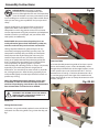
AXMINSTER Code 501249 Hobby SERIES AWC4 250mm DeLuxe Combination Machine AT&M: 15/09/2014 REF: 508306 Index of Contents Index of Contents 02 Declaration of Conformity 02 What’s Included 03 General Instructions for 230V Machines 04 Specific Safety Precautions 05-06-07 Specification07 Assembly Instructions 08-09-10-11-12-13-14-15 Positioning the Machine 15-16 Machine Foot Print 16-17 Illustration and Parts Description 18-19-20-21-22-23-24-25 Setting Up the Machine 26-27-28 Operating Instructions 28-29-30-31-32-33-34-35 Routine Maintenance 35 Parts Breakdown/List 36-37-38-39-40-41-42-43-44-45-46-47-48-49-50-51-52-53 Wiring Diagram 54 Cutter Block Accessories 55 Declaration of Conformity Copied from CE Certificate Manufactured by Laizhou Planet Machinery Co., Ltd. is in compliance with the standards determined in the following Council Directive. The undersigned, T. Fuhrmann Authorised by Laizhou Planet Machinery Co., Ltd. Yutai West Street 261400 P.R. China. EN 55014-1: 2006+A1 EN 61000-3-2: 2006+A1+A2 EN 61000-3-11: 2000 EN 55014-2: 1997+A1+A2 Model Number: ML353G (Combined Woodworking Machine) Warning Fully read manual and safety instructions before use Ear protection should be worn The symbols below advise that you follow the correct safety procedures when using this machine. Eye protection should be worn 2 Dust mask should be worn HAZARD Motor gets hot What’s Included Model Number: ML353G Panel Saw: 1 No. 1 No: 1 No: 1 No: 1 No: 1 No: 1 No: 1 No: 2 No: 1 No: 1 No: 1 No: 250mm AWC4 DeLuxe Combination Machine (95% assembled) Rip Fence Assembly 250mm Saw Blade Saw Guard Flexible rubber Hose with Support Rod Adjustable Work Clamp Assembly Depth Stop Bracket Sliding Table Guide Rail Sliding Table Guide Rail Stops Sliding Table Extension Sliding Table Extension Support Casting Sliding Table Extension Fence (with Adjustable Depth Stop) Spindle Moulder: 1 No: Spindle Moulder Guard Assembly (Fully Assembled): Planer/Thicknesser:Tools: 1 No: Planer Fence 1 No: Planer Fence Mounting Base 1 No: Fence Securing Bracket 1 No: Overhand Planer Guard Mounting Bracket 1 No: Overhand Planer Guard 1 No: Overhand Planer Guard Locking Plate 1 No: Spring Metal Plate 2 No: M10 Washers 2 No: M10 Lever Handle Bolts 2 No: M6 x 12mm Cap Head Bolts 2 No: M6 Eye Bolts (for lifting) Wheel Mobility Kit: 1 No: 2 No: 1 No: 10 No: Mobility Operating Handle Adjustable Wheel Carriages Lifting Bracket M8 Cap Head Bolts and Washers 1 No: Manual 3 1 No: 1 No: 1 No: 1 No: 1 No: 1 No: 1 No: 1 No: 1 No: 1 No: 1 No: 1 No: 1 No: 1 No: Blade Setting Tool 12mm Hex Key 10mm Hex Key 8mm Hex Key 6mm Hex Key 5mm Hex Key 4mm Hex Key 3mm Hex Key 7/5.5mm Spanner 8/10mm Spanner 13/16mm Spanner 36/41mm Spanner 16mm Socket Spanner Tommy Bar General Instructions for 230V Machines Good Working Practices/ Safety The following suggestions will enable you to observe good working practices, keep yourself and fellow workers safe and maintain your tools and equipment in good working order. It is good practice to leave the machine unplugged until work is about to commence, also make sure to unplug the machine when it is not in use, or unattended. Always disconnect by pulling on the plug body and not the cable. Once you are ready to commence work, remove any tools used in the setting operations (if any) and place safely out of the way. Re- connect the machine. WARNING! KEEP TOOLS AND EQUIPMENT OUT OF THE REACH OF YOUNG CHILDREN Carry out a final check e.g. check the cutting tool, drill bit etc., are securely tightened in the machine, check you have the correct speed and function set, check that the power cable will not ‘snag’ etc. Mains Powered Tools Mains Powered Tools Primary Precautions This machine is supplied with a moulded 16 Amp. Plug and 3 core power cable. Before using the tool inspect the cable and the plug to make sure that neither are damaged. If any damage is visible, have the tool inspected/repaired by a suitably qualified person. If it is necessary to replace the plug, it is preferable to use an ‘unbreakable’ type that will resist damage on site. Only use a 16 Amp plug, and make sure the cable clamp is tightened securely. Fuse as required. If extension leads are to be used, carry out the same safety checks on them, and ensure that they are correctly rated to safely supply the current that is required for your machine. Make sure you are comfortable before you start work, balanced, not reaching etc. If the work you are carrying out is liable to generate flying grit, dust or chips, wear the appropriate safety clothing, goggles, gloves, masks etc. If the work operation appears to be excessively noisy, wear ear-defenders. If you wear your hair in a long style, wearing a cap, safety helmet, hairnet, even a sweatband, will minimise the possibility of your hair being caught up in the rotating parts of the machine, likewise, consideration should be given to the removal of rings and wristwatches, if these are liable to be a ‘snag’ hazard. Consideration should also be given to non-slip footwear, etc. If you are allowing another person to use the machine, ensure that they are suitably qualified to use it. Work Place/Environment The machine is not designed for sub-aqua operation, do not use when or where it is liable to get wet. If machine has got wet; dry it off as soon as possible with a cloth or paper towel. Do not use 230V a.c. powered tools anywhere within a site area that is flooded or puddled, and do not trail extension cables across wet areas. Keep the tools clean; it will enable you to more easily see any damage that may have occurred. Clean the tools with a damp soapy cloth if needs be, do not use any solvents or cleaners, as these may cause damage to any plastic parts or to the electrical components. Do not work with cutting or boring machine of any description if you are tired, your attention is wandering or you are being subjected to distraction. A deep cut, a lost fingertip or worse is not worth it! Do not use this machine within the designated safety areas of flammable liquid stores or in areas where there may be volatile gases. There are very expensive, very specialised machines for working in these areas, THIS IS NOT ONE OF THEM. Keep the work area as uncluttered as is practical, this includes personnel as well as material. Check that cutters, drills etc., are the correct type and size, are undamaged and are kept clean and sharp, this will maintain their operating performance and lessen the Under no circumstances should CHILDREN be allowed in loading on the machine. Above all, OBSERVE…. make work areas. sure you know what is happening around you, and USE YOUR COMMON SENSE. 4 Specific Safety Precautions Panel Saw Do not attempt to carry out cross cutting operations ‘freehand’, always use the mitre fence for small material and the sliding carriage for larger work pieces. Unless you Do not force the saw, if the saw begins to ‘stall’ you are are an experienced machine operator, do not attempt to ‘forcing the cut’ or over working the saw. Ensure that the ‘rip’ freehand, always use the guiding facility of the rip saw blade is clean and sharp. Resin build up on the blades fence. It is perfectly acceptable to support, guide, and feed will increase the friction of the saw passing through the the timber with your hands whilst ripping stuff of some timber, and cause over heating of the blade, blunt teeth length, however, as you approach the blade ensure that will work harder tearing the fibre of the timber as the push stick is to hand, and you use it. opposed to shearing it, also with subsequent overheating. Both faults unnecessarily load the machine beyond Remember the emphasis of the ‘push’ should be between normal usage, and shorten its longevity. the blade and the fence and close to the fence. Use your free hand to support and guide the material on the Do not use blades that are deformed in any way. offside of the saw blade and at least 100mm away from it. If the timber does not extend to at least 100mm to the Do not remove the blade guard. The design of the riving offside of the saw blade, the material possibly does not knife on the machine will not allow for slotting or ‘blind’ need guiding or supporting. grooving, so there is no reason to remove the guard. There is adequate clearance under the guard for the capacity of Check (especially on site), that there are no foreign the machine (75mm). objects e.g. old nails, screws, small stones etc embedded in the material you are about to cut. If necessary take a Do not remove the riving knife. wire brush to the timber before working. Make sure the saw blade is the correct type for the job in hand. Do not use any blades that cut a smaller kerf than the riving knife thickness. Make sure the riving knife is correctly adjusted to the blade and is securely fastened. If the table insert becomes damaged or broken, and will not support the timber ‘up close’ to the blade, replace it. If you are being assisted whilst using the saw (by a ‘take off’ or ‘support’ number?), remember there is only one sawyer at a machine, and they stand in front of it. The assistant does not push, pull, guide etc., unless specifically asked or instructed to do so by the sawyer. Do not start the saw with the work piece touching the blade. Spindle Moulder Do not commence sawing until the blade has run up to full speed. After switching off, never try to slow the saw down more quickly by applying side pressure (with a piece of wood?) to the blade. Apply the old joiner’s adage of never getting hands within one handbreadth of the blade. Leave the machine disconnected from the mains supply until you are about to commence work. Always disconnect the machine if you are leaving it unattended. This machine is designed for shaping wood and wood derived materials. Authorised Use Machining of other materials is not permitted and may be carried out in specific cases only after consulting with the manufacturer. The proper use also includes compliance with the operating and maintenance instructions given in this manual. Never leave the vicinity of the machine unless the blade has come to a complete stop. The machine must be operated only by persons familiar with its operation and maintenance and who are familiar with its hazards. Do not attempt to carry out any maintenance, corrective work, setting up etc., unless the machine is disconnected from the mains supply. If any tools have been used during The required minimum age must be observed. The setting up procedures, make sure they are removed from machine must only be used in a technically perfect the machine and stowed safely away. condition. When working on the machine, all safety mechanisms and covers must be in operation. 5 Continues Over.... Specific Safety Precautions In addition to the safety requirements contained in these Operating Instructions and your country’s applicable regulations, you should observe the generally recognized technical rules concerning the operation of woodworking machines. Planer/Thicknesser No changes to the machine may be made. Disengage the autofeed for the thicknesser. Ensure both tables are correctly seated and locked down. Ensure the dust extraction hood is in place and is not blocked. Fit dust extraction. Most machines currently are well interlocked to ensure that the machine must be in the correct configuration to perform one task or the other. Make yourself familiar with these configurations and do not try to use the machine in a half and half state, or rig the interlocks to enable you Any other use exceeds authorisation. to do so. These machines are designed for cutting timber only. They will, but are not designed to, cut timber In the event of unauthorised use of the machine, the manufacturer renounces all liability and the responsibility derivatives or composites. Glue lines in plywood, block board etc, will ‘notch’ the blades. The bonding agent in is transferred exclusively to the operator. chipboard is likewise detrimental to the health of your planer knifes. It is best to leave them alone. If you have General Safety Notes to machine composites, work out the costs of tungsten, against HSS (plus the sharpening costs), and proceed Woodworking machines can be dangerous if not used accordingly. On larger machines it is common practice to properly. Therefore the appropriate general technical leave a portion of the blade (usually the offside 30 mm) to rules as well as the following notes must be observed. be used on ‘aggressive’ materials. Read and understand the entire instruction manual Overhand Planing before attempting assembly or operation. Make sure during overhand planing operations, that the Keep these Operating Instructions close by the machine, fence is set to the required angle, is securely fastened and locked in position. Ensure the planer block guarding is in protected from dirt and humidity, and pass them over to position and secured. the new owner if you part with the tool. Daily inspect the function and existence of the safety appliances before you start the machine. Check the sharpness of planer knifes, check for ‘nicks’ and ‘notches’, if there are damaged sections on the blades, try to plane in the ‘clear’ areas. Remove all loose clothing and enclose long hair. Before operating the machine, remove tie, rings, watches, other jewellery, and roll up sleeves above the elbows. Especially when planing material down to ‘thin’ dimensions, maintain pressure on the ‘front’ of the material i.e., that portion of the stuff that has passed over the block, but use a push stick or a pusher shoe to clear the end of the stuff over the block. Wear safety shoes; never wear leisure shoes or sandals. Always wear the approved working outfit. Do not wear gloves while operating the machine. Thicknessing For the safe handling of cutting tools wear work gloves. When thicknessing, remove the fence. Lower the thicknessing table slightly. Control the stopping time of the machine, it may not exceed 10 seconds. Unlock and swing both tables ‘up and out of the way’, taking care not to foul the overhand guard/arm assembly, which will probably swing free. Remove cut and jammed work pieces only when the machine is at a complete standstill and motor is turned off. Turn the dust extraction hood up and over the block. Install the machine so that there is sufficient space for safe operation and work piece handling. Connect the dust extraction. Ensure the hose will not foul the wood when being passed through the machine. Keep work area well lit. 6 Specific Safety Precautions NOTE, Consideration should be given to the type of finish you will be applying to the wood when you select your cleaning/lubrication agent. Some compounds won’t mix. i.e. PTFE and Acrylic. Check the height of the thicknessing table. Engage the autofeed mechanism. Periodically, clean any excess build up of resin from the thicknessing table, and apply any proprietary brand of lubricating agent. Specification ModelAWC4 Code501249 RatingHobby Power 3,000W (Saw) 2,000W ( Planer) 3,000W (Spindle) 230V Number of Motors 3 Blade Speed 4,050rpm Blade Tilt 0 - 45° Blade Dia/Bore 250mm x 30mm Table Size 1,200 x 840mm (Saw) 250 x 1,050mm (Planer) 250 x 600mm (Thicknesser) Max Ripping Width 460mm Max Depth of Cut @ 45˚ 45mm Max Depth of Cut @ 90˚ 65mm Max Planing Width 250mm Sliding Table Size 1,200 x 120mm Cutterblock Speed 4,000rpm Cutterblock Diameter 75mm Knives HSS x 3 Feed Speed 8m/min Max Thicknesser Capacity 180mm Spindle Speed 3,500, 5,500, & 7,500rpm Spindle Diameter 30mm Spindle Travel 130mm Max Tooling Diameter Above Table 140mm Dust Extraction Outlet 100mm x 3 Weight370kg 7 Assembly Instructions PLEASE NOTE: Some of this assembly procedure is best accomplished by two persons. Although the tasks are not impossible, some of the items are heavy and awkward, and a mishandling error could cause injury. Please think about what you are doing, your capabilities and your personal safety. Fig 01 Unpack all the boxes and check all the components against the “What’s in the Boxes’ List. If any parts or components are missing, please contact our customer services department using the procedures and telephone numbers listed in our catalogue, and you will be dealt with quickly and efficiently. M6 Caphead screw/nut PLEASE NOTE: that, on occasion, the packing list is not strictly adhered to, please check all the boxes, packets etc, to make sure that all the parts have been accounted for. Having unpacked the boxes, (please dispose of any unwanted packaging responsibly), put the parts and components whereby they are readily to hand. Break down the main box by knocking the sides away (be careful of exposed nails etc.), but leave the machine sitting on its pallet. Remove the protective grease film that is coating all the unpainted parts of the machine. Use a proprietary de-greasing agent or paraffin. Unfortunately, this cleaning process is always a bit ‘mucky’ especially if you tackle the job with a high level of enthusiasm. You are advised to wear overalls or coveralls etc., during the process. After cleaning, especially if you used paraffin, lightly coat the exposed metal surfaces to prevent any rusting. 5mm Hex key Extension Table 1). Locate the table extension guide rail and two square inserts and butterfly screws. Insert the butterfly screws through the pre-drilled holes in the angle brackets, screw on the square inserts and slot them into the ‘T’ slots on the extension rail see fig 2. Position the extension rail so it’s over hanging more to the right of the machine and tighten the butterfly screws to clamp the extension rail in position, see fig 3. Note: The AWC4 Combination Machine comes 95% assembled, in order to reduce the footprint of the machine for packaging, several items are dismounted from the machine and need to be re-affixed. Fig 02-03 Butterfly screw WHEN YOU FIRST RECEIVE YOU COMBINATION MACHINE IF YOU INTEND TO USE THE SPINDLE MOULDER FIRST PLEASE GO TO PAGES 12-13 FOR ASSEMBLY INSTRUCTION. Panel Saw Fitting the Saw Guard Locate the saw guard and M6 caphead screw and M6 nut and attach it to the riving knife using a 5mm hex key, see fig 1. 8 Square insert Assembly Instructions 2) Locate the steel pin plate (A) , line up the pins with the elongated slots in the extension table (B) and lower the plate into the table, see fig 4. Locate the two lift and shift MAKE SURE THE SUPPORT CASTING WHEEL RUNS SMOOTHLY ALONG THE EXTENSION RAIL! Fig 04 5) On top of the extension table there are two adjustment caphead screws, using a straight edge adjust the screws until both sliding and extension tables are level. A Fig 07-08 Straight edge B Lift and shift handle handles and slot them through the two pre-drilled holes in the extension table (B) and screw them into the threaded holes in the steel pin plate (A). NOTE: Make sure to leave sufficient clearance between the steel plate and the table frame for the next step. Caphead screw 3) Position the extension table (B) against the sliding table assembly. Line up the steel pin plate (A) with the ‘T’ slot to the end of the sliding table and slide on the extension table (B), see fig 05. 4) Position the extension table so it’s roughly centred to the sliding table and tighten the two lift and shift handles to lock the asssembly in position, see fig 6. Fig 05 Caphead screw Sliding Table Fence Locate the sliding table fence, loosen the angle bracket clamp by undoing the butterfly knob (A), loosen the steel pin by releasing the clamping handle beneath the fence, see fig 9. Line up and push the steel pin into one of the Clamping handle Fig 06 Fig 09 B A Steel pin Sliding table fence 9 Continues Over.... Assembly Instructions two pre-drilled holes on top of the extension table, see fig 10. Lift-up the 90˚ stop located to the corners of the extension table, push the fence up against the 90˚ stop, see fig 11 and clamp the angle bracket (A) to the table’s steel girder by tightening the butterfly knob, see fig 12. Re-tighten clamping handle to lock the fence in position, see fig 10. Fig 13 Butterfly nut Fig 10 Clamping handle Steel pin Steel square clamp Work Clamp Pre-drilled hole Fig 11-12 Locate the work clamp assembly, loosen the clamping ring, slot the clamp assembly into the sliding table’s ‘T’ slot and tighten the ring to clamp the assembly in place., see fig 14. Fig 14 90˚ Stop Clamping ring A Dust Extraction Hose Locate the ‘Y’ rod which will support the flexible hose and screw the threaded end into one of the pre-drilled holes on top of the planer/thicknesser chassis, see fig 15. Attach one end of the hose to the moulded outlet in the Butterfly saw guard, (make sure it is a snug fit) see fig 16. Attach the other end to the dust extraction outlet, see fig 17. Lower the hose into Workstop Plate the ‘Y’ support rod to raise the hose clear of the work Fit the workstop plate by loosening the butterfly nut, table, see fig 18. insert the steel square clamp into the ‘T’ slot on the sliding table and re-tighten the butterfly nut, see fig 13. Fig 15 10 Assembly Instructions Fig16 Fig 19 Flexible hose End cover Fig 17 Fig 20-21 Flexible hose C M8X50 Bolt ‘T’ Slot Dust extraction outlet Fig 18 4) Replace the cover to the end of the guide rail (C) and secure with the Phillips screws you removed earlier. Position the rail so it lines up with the edge of the saw table and only finger tighten the nuts at this point, see fig 22. Rip Fence Assembly Fig 22 Locate the rip fence (A), rip fence extension (B) with ‘T’ bolts, washers and clamping knobs, fence guide rail (C) and two M8 x 50 bolts and nuts. 1) Insert the two M8 bolts into the pre-drilled holes to the side of the main saw table and loosely screw on the nuts. C 2) Remove the cover to the end of the fence guide rail (C) by removing the two Phillips screws, place safely aside, see fig 19. 3) Line up the first bolt head with the ‘T’ slot in the fence guide rail and slide on the rail, repeat for the remaining bolt, see figs 20-21. 11 Continues Over.... Assembly Instructions 5) Locate the rip fence (A) and lower the clamp assembly over the guide rail (C), see fig 23. Rip-Fence Extension 1) Locate the rip fence extension (B) and the two ‘T’ bolts, washers and clamping knobs. Slide the ‘T’ bolts into the ‘T’ slot to the end of the fence extension casting, see fig 27. Fig 23- 24 2) Line up the ‘T’ bolt threads and insert them through the two pre-drilled holes to the side of the rip fence, push the fence extension up against the fence and secure in place with the two clamping knobs and washers, see figs 28-29. ‘T’ Slot Fig 27 A Mounting Bracket ‘T’ bolt 6) Locate the micro adjuster assembly (D) and remove the mounting bracket by removing the two Phillips screws, place safely aside. Remove the end cover from the fence clamp assembly (A) and place aside. Insert the mounting bracket into the ‘T’ slot to the side of the fence casting assembly, see fig 24. Line up the pre-drilled holes in the micro adjuster with the holes in the mounting bracket, making sure the pinion engages into the rack beneath the fence guide rail (C), secure the micro adjuster with the two Phillips screws you removed earlier, see figs 25-26. B Fig 28-29 Fig 25 B D A Fig 26 Rack D Pinion 12 Clamping knob Assembly Instructions 3) Raise the saw blade to it’s highest point and slide the fence assembly (A) up against the blade and adjust the fence guide rail (C) until the pointer reads ‘0’on the scale then tighten the two nuts beneath the arm rail to secure the assembly, see fig 30. Fig 30 Mount the overhand plane guard arm onto the side of the out feed table that corresponds to your preferred handing, then fit the overhand cutter block guard. In the accessories packet there is a small spring metal plate, this fits into the overhand guard clamping assembly to spread the load of the guard clamp onto the guard. It also prevents the bolt scoring the upper surface of the guard, fasten in position using the guard lock,see fig 33-34. Fig 32 Fence support bracket Blade A Planer fence base Clamp Clamping handles Scale Fig 33-34 Pointer Plane guard arm Planer/Thicknesser Locate the fence mounting bracket and fix to the machine casting as shown in fig 31, using 2 No. M6 x 12mm caphead bolts, depending on your preferred handing. Introduce the planer fence base into the bracket; so that the planer fence base slides into the fence mounting bracket; then secure; position the fence approximately mid-table, see fig 32. Guard arm clamp handle Cutter block guard Fig 31 Guard clamp Spring metal plate Caphead bolt Mounting bracket 13 Continues Over.... Assembly Instructions Spindle Moulder WARNING!! DISCONNECT THE MACHINE FROM THE MAINS BEFORE CONTINUING! NOTE: IN ORDER TO INSTALL THE SPINDLE MOULDER ASSEMBLY THE FOLLOWING COMPONENTS NEED TO BE REMOVED. 1) Remove the panel saw rip fence by lifting the locking lever up and lifting the fence away from the guide rail, place safely aside. 2) Disconnect the dust extraction hose from the saw guard, remove the guard and place safely aside then lower the saw beneath the table. 4) Remove the planer/thicknesser fence assembly by undoing the two M6 caphead bolts on the mounting bracket and placing the fence assembly safely aside. 2) Lift the spindle guard assembly onto the work table, manoeuvre the assembly over the pre-drilled holes in the table. Insert threaded clamping handles through the elongated slots and align the two pre-drilled threaded holes on either side of circular ring, see fig 38. 3) Loosely screw the guard assembly down onto the table, see fig 39-40. Fig 38-39-40 5) Remove the workstop plate. The spindle moulder guarding comes fully assembled but is not yet mounted to the work table, see instructions below for mounting the spindle moulder assembly. Pre-drilled holes 1) Remove the circular rings from the work table and place aside, see fig 35-36-37. Fig 35-36-37 Elongated slot Spindle guard assembly Threaded clamping handle 14 Assembly Instructions 4) Place a 90˚degrees square against the fence and adjust the assembly until the fence is perpendicular to the table, tighten the clamping handles to lock the guard in place, see fig 40. Fig 40 Fig 42-43 Fence M8 Cap head bolts Square C Lifting point hole Wheel Mobility Kit The wheel mobility kit enables the combination machine to be moved easily to a new location. The kit comprises of two adjustable wheel carriages (A) that bolts to each side of the machine, a mobility operating handle (B) and lifting bracket (C). Follow the instruction below to assemble the kit. Positioning the Machine 1) Put to hand eight M8 cap head bolts and washers and the two wheel carriages (A). Line up the four holes in one of the wheel carriages mounting brackets with the four threaded holes to one side of the machine and secure using the M8 cap head bolts and washers, see figs 41. Tighten using the supplied Hex key. Repeat for the remaining wheel bracket. Ascertain the orientation of the machine and move it to its desired position in the workshop. Ensure that the machine is positioned to allow sufficient clearance all round to cater for the maximum length of timber you wish to machine. The machine should be positioned on a flat level surface. Fig 41 M8 Cap head bolt Manoeuvring the Machine 1) Turn the “raise and lowing bolts” on the wheel carriages clockwise until the rear feet are lifted away from the floor then nip up the locking nut to secure the setting. Raise and lowing bolt 2) Locate the mobility operating handle (B), insert the handles lifting bar into the hole in the lifting bracket (C), see fig 44 and push down the handle to raise the machine. Pivot bolt A Locking nut 2) Locate the lifting bracket (C) and two M8 cap head bolts and washer. Line up the two pre-drilled holes in the bracket with the threaded holes to the base of the machine and secure in place with the M8 cap heads, see figs 42-43. Fig 44 Handle lifting bar B 15 Continues Over.... Positioning the Machine Fig 45 3) Manoeuvre the machine to the chosen location making sure there is sufficient space all round, then carefully lower the machine down, see fig 45. 4) With the machine in position lower the rear feet by loosening the two “raise and lowering bolts”, on the wheel carriages (A), fig 41. 2200mm Machine Foot Print 1600mm 16 Machine Foot Print Sliding Table 2020mm Sliding Table 1920mm 17 Illustration and Parts Description Spindle Moulder Set Up Panel Saw Set Up 18 Illustration and Parts Description Planer Set Up Thicknesser Set Up 19 Illustration and Parts Description Flexible hose ‘Y’ support rod Saw guard Saw table Rip fence Sliding table Table extension fence 3 Way control switch assembly Guide rail Main emergency stop Tilt control hand wheel Planer out feed table Spindle moulder assembly Saw table Fence assembly Distance stop Table extension Panel saw rise and fall control handle wheel Telescopic extension Carriage wheel assembly Table extension support 20 Guide rail stop Illustration and Parts Description Guide roller height clamping knob Guide arm clamp Guide arm Anti-kickback clamping knob Clamping knob Guide roller height clamping knob Anti-kickback height clamping knob Fence adjusting knob Anti-kickback assembly Fence advancing knob Guide roller assembly Fence advancing clamping knob NVR On/Off switch ‘O’ for OFF ‘I’ for ON Work clamp Power selector switch ‘R’ for Spindle Moulder/ Panel Saw, ‘I’ for Planer Thicknesser Selector switch ‘0’ No Function ‘1’ Spindle Moulder ‘2’ panel Saw Sliding table locking knob 21 Illustration and Parts Description Height adjuster knob Work clamp Cutter block guard adjuster Mounting arm lock Fence rail Fence Spindle moulder rise/fall control handle wheel Out feed table adjuster Thicknessing table rise and fall control Cutter block guard Cutter block guard clamp Spindle moulder access door ON/OFF Switch Planer/ Thicknesser Foot Planer in feed table Dust extraction Rip-Fence Fence extension Dust extraction outlet Spindle moulder circular rings Out feed table Spindle moulder access door lock Cutter block guard In feed table In feed table adjuster Spindle height lock Thicknesser table 22 Illustration and Parts Description A A B A B Cam lock (A), Table height locating bolts (B) to level the table with the cutter block blade Feed scale overhand (A) Pointer (B) Feed table locking handle (A) A A Sliding table height assembly (A) A A Saw table height adjusters (A) Autofeed engage control (A) Panel saw rise and fall control butterfly handle lock Thicknesser rise and full scale C B Planer/Thicknesser ON/OFF switch (A) Emergency stop (B), Rise/Full clamp (C) B D B A A C Cutter block (A), In feed roller (B), Out feed roller (C), Anti kickback fingers (D) C 23 Tilt angle scale (A), Pointer (B), Tilt handle lock (C) Illustration and Parts Description F D H A C G E B Fence securing clamp (A), Fence mounting bracket (B), Planer fence base (C), Elongated fence support bracket (D), Fence locking handle (E), Fence positioning knob lever (F), Fence adjusting bolt (G), Spindle moulder circular rings (H) C D A E B Rip fence locking handle (A), Rip fence micro adjuster (B), Magnifying glass (C), Fence rail scale (D), Fence rail rack (E) 24 Illustration and Parts Description A B Magnifying glass C Riving knife (A), Saw blade (B), Scoring blade (C) Distance stop assembly Butterfly clamp Telescopic extension assembly 90˚ degree extension fence stop Main emergency stop button B A Spindle moulder motor assembly (A) and motor door micro switch (B) 25 Setting Up the Machine the angle scale reading is correct. Set the rip fence a predetermined distance from the saw blade and lock in position. Check that the rip fence is held securely when it is locked in position. If the locking appears a little ‘slack’, adjust the position of the clamping lug at the rear of the rip fence by tightening the nut. WARNING!! DISCONNECT THE MACHINE FROM THE MAINS BEFORE CONTINUING! Panel Saw Raise the blade to its maximum height, check that is upright to the table. Slacken the angle bracket clamp by undoing the butterfly nut (A) and the steel plate pin assembly by loosening the clamping handle (B), see fig 46 and slide the fence up close to the saw blade. Secure the fence again as described above. Fig 46 B A Setting Scoring Blade 90˚ Degrees Lower the saw assembly with the Rise and fall control hand wheel until the scoring saw is just below the table, using a straight edge adjust the cap head screw (A), set the saw blade to the desired height using the Hex key provided, turn (clockwise to raise the blade and anti-clockwise to lower the blade), until the scoring saw is level with the table, then recheck the height of the scoring and adjust to 1 or 2mm if required. Lock the scoring blade in position using the cap head screw (B), see figs 48-49. Fig 48-49 A Fig 47 Make sure the extension fence is up against the 90˚ extension fence stop, see fig 47 and using a 90˚ square, place it against the fence and the blade (not on the teeth), check that the angle is correct, if not, adjust the 90˚ extension fence stop nut/bolt until the fence is square to the blade. Nut/bolt B Scoring blade Loosen the butterfly nut (A) and handle (B) as described above, slide the nose of the fence (the black tongue) up to the blade, secure. Check the parallelity of the sliding table movement by sliding the table forward and checking the tongue/blade are still in contact, or that the movement has not jammed the tongue against the saw. If there is a 45˚ Degrees slight discrepancy, it may be acceptable to you (a 1mm difference across the face of the blade (fully extended) is With the blade assembly at 90˚ degrees, turn the cap head about one quarter of a degree). screw (A) one and half turns anticlockwise, (you may need to change to get the desired scoring blade height). Lock Tilt the blade fully over. Using a mitre square, set the angle the scoring blade in position using the cap head screw of the saw to 45˚. Check that the index mark gives a (B). Lower the saw assembly until the scoring saw is just corresponding reading against the scale. Adjust the below the table. Then tilt the blade assembly until it reads pointer if necessary. Reset the blade upright, check that 45˚ degrees on the tilt angle scale, check that the scoring 26 Setting Up the Machine blade is sitting just proud of the table, see fig 50. Fig 50 Connect the machine to the mains supply, press the power selector switch to the ‘I’ position for spindle moulder/panel saw, turn the selector switch to ‘2’ panel saw (see page 21) and give the machine a quick burst. i.e. On/Off. Check that everything is sound and feels O.K. (No knocking, scraping, belt squeal, rubbing etc.,) Reconnect the mains, give the machine a longer run, and press the emergency stop button on the front of the machine. Check that the blade comes to a complete stop. When you are happy that everything seems OK, switch the machine off, disconnect from the mains supply. Spindle Moulder WARNING!! DISCONNECT THE MACHINE FROM THE MAINS BEFORE CONTINUING! NOTE: If you change the main blade saw blade at anytime, the kerf width of the replacement blade must be slightly narrower, (3.2mm) than the kerf width of the scrolling blade. Spindle Speed Setting The spindle speed must be selected according to the cutting diameter. The speed is set by changing the V-belt location on the pulleys, see diagram below. H With the blade assembly at 90˚degrees, turn the cap head Upper location (H)....7000rpm Centre location screw (A) one and half turns anti-clockwise. Lock the (M)....5500rpm Lower location (L)....3500rpm scoring blade in position using the cap head screw (B). Lower the saw assembly until the scoring saw is just 7000rpm below the table. 5500rpm M Tilt the blade assembly until it reads 45˚degrees on the tilt angle scale, check that the scoring blade is sitting just proud of the table. L 3500rpm Spindle Pulley Alignment Screw Turn the alignment screw as required to align the scoring blade with the main blade, see fig 51. Motor Pulley PLEASE NOTE: If the spindle speed is set at (3500rpm) and the tool diameter is smaller than 120mm there is an increased risk of the work piece kicking back at you! Fig 51 The Cutting Tool The cutting tool may only be changed when the spindle rotation lock is engaged and the mains plug is pulled. There is a risk of personal injury by cuts from the cutter knives. Wear suitable gloves when changing cutters. Blade alignment screw Check that everything that should be tight, is tight; saw blade guard, rise and fall lock mechanism, fence clamps etc. Clean all surfaces of cutters and spindle arbor with a suitable solvent. Only use tooling with manual feed cutter blocks marked “MAN”. 27 Continues Over.... Setting Up the Machine Unsuitable, incorrectly mounted, dull, cracked or bent cutter knives can break or increase the risk of kickback considerably. Close up the aluminium fences to give approximately 5mm clearance around the cutter, see diagram below. The installation of sanding or polishing tools is not permissible. Spindle Fence Fence The cutter block must be positioned on the arbor as low as possible, see diagrams below. 5mm The fence is used to guide small work pieces through the cutter without them being trapped between the fence and the cutter. The top cover should be kept closed when the machine is in operation; it can be opened to give access to the cutter when the machine is stationary. The dust extraction hose is connected to the aperture at the rear of the fence casting. Before starting work, carefully check that the cutter can rotate freely without fouling the inside of the guard and that the guard is clamped firmly in place. Operating Instructions Planning Function Watch the direction of rotation (counter-clockwise) when mounting the cutter. Fill the space between cutter and clamping washer with spacing collars. To operate the planer correctly, it is recommended to read the HSE (Health and Safety Executive) information working sheet on the safe use of handfed planing machines, see image below. Tighten the arbor cap head screw securely. Don’t use a wrench extension or a hammer to tighten the cap head screw. Cover the clearance zone around the cutter with table insert rings, see figs 35-36-37. Setting the Fence Adjust the position of the fence assembly to give both the required cutter protrusion and adequate clearance between the cutter and the fence. 28 Operating Instructions Fig 53 Power On Procedure: 1) Rotate the selector switch (A) in the vertical position. 2) Press the selector switch (B) to select the planer/thicknesser icon (I). Green button 3) Press the NVR ON/OFF switch (C) to the “ON” position, then press one of the green “ON" buttons to start the machine, see figs 52-53. Thicknessing Function • Rotate the cutter guard arm out of the way. • Remove the fence assembly. Green button • Unlock the in feed/out feed tables, rotate to the side. • Use a honing guide to sharpen the blades. • Rotate the dust extraction hood. • Measure the timber thickness, raise the thicknessing table & reading against the scale, until the desired measurement is reached and lock the table in position. Spindle Moulder Function Power On Procedure: •Release the main emergency stop button on the planer/thicknesser. 1) Rotate the selector switch (A) to the spindle moulder icon (1). Power On Procedure: 1) Rotate the selector switch (A) in the vertical position. 2) Press the selector switch (B) to select the spindle moulder/panel saw icon (R). 2) Press the selector switch (B) to select the planer/thicknesser icon (I). 3) Press the NVR ON/OFF switch (C) to the “ON” position, to start the spindle moulder, see fig 54. 3) Press the NVR ON/OFF switch (C) to the “ON” position, then press one of the green buttons to start the machine, see figs 52-53. Fig 54 Fig 52 C C B B A A 29 Continues Over.... Operating Instructions Correct Operating Position Fig 55 Position yourself offset to the machine as shown above C B Work Piece Handling A •Feed the work piece straight across the machine table, holding the fingers close together and guiding the work piece with the palms of your hands. •Never put your hands under or behind the cutter guard. •Always keep your hands well clear of the rotating cutter. •Always feed the work piece against the cutter rotation as shown by the arrow in illustration. 4) Regulate the cutting height by raising or lowering the rise and fall control hand wheel (A). Lock the blade in place by turning the Rise & fall control handle lock. •Use a push stick when working the ends of narrow stock. •Use a feeding aid if you are going to machine a work piece shorter than 300mm. •Always machine the work piece over its entire length. A Recess machining may only be carried out with the aid of suitable longitudinal work piece stops. •When working complex shapes, make jigs and guides to guide the work piece properly and safely. 5) Adjust the rip-fence extension (B) to the desired position by loosening the two rip fence extension butterfly knobs (C) then tighten the knobs. Set the height of the guard to 3-4mm above the work piece and lock it in position. When done, lower the guard to board level. •Make trial cuts on a piece of scrap before working the actual work piece. •Support long work pieces with roller stands or table extensions. •Always work one work piece at a time. Panel Saw Function Power On Procedure: C 1) Rotate the selector switch (A) to the panel saw icon (2). B 2) Press the selector switch (B) to select the spindle moulder/panel saw icon (R). 3) Press the NVR ON/OFF switch (C) to the “ON” position, to start the panel saw, see fig 55. 30 Operating Instructions 6) • Check that the room is well lit. Planer/Thicknesser Blades • Make sure that the saw table is clear of any tools. WARNING!! DISCONNECT THE MACHINE FROM THE MAINS BEFORE CONTINUING! • Check that the saw guard is against the top of the board. • Start the saw, wait until the saw is at full speed, use a push stick (D) to safely push the work piece through. • Turn off the saw, wait until the saw comes to a complete stop before removing the board. D 7) Use the extension table/fence when cutting large pieces of board at 90˚. The planer blades are mounted into 3 slot housings machined in the cutter block. The slot housing comprises of a slot cut on a radial axis with a reverse tapered slot alongside it, see fig 56. The depth of the first slot governs the seating of the chip breaker/wedge, the second slot allows the blade to be set to its correct depth in the block. The chip breaker/ wedge is machined with a tapered face set at the same angle as the slot. This allows the blade to be clamped between parallel faces. The block will accept blades 250mm x 3mm x 30mm. After sharpening, the blades will reduce over their height dimension, but the blades can be safely used until their overall height dimension is 17mm, then the blades must be discarded as they can no longer be securely clamped in the housing. The reverse taper slot has a series of blind holes bored in the bottom surface into which springs are fitted. These springs act against the bottom of the planer blade, to push it into contact with the setting tool, when the blades are being positioned after changing. Fig 56 Chip breaker/wedge Planer knife Spring Clamping Nut 8) There is an angle scale mounted on top of the extension table, to set the fence at required angles for cutting parallel cuts. Changing the Blades Angle scale Locate the 5.5mm x 7mm A/F spanner in the tool kit. Turn the cutter block until one of the slots is uppermost, (between the tables). Using the spanner drive the 5 No. bolts into the chip breaker/wedge, thus removing the clamping effect. This should allow the blade to ‘spring’ up to protrude clear of the edge of the cutter block. Carefully remove the blade, lay aside. Remove the chip breaker/wedge, lay aside, finally remove the springs 31 Continues Over.... Operating Instructions from the slot and lay them aside. Repeat the process for the other two blades. If the block becomes difficult to hold located, being out of balance with the blade/s removed; use a thin wedge of material to jam the cutter block in position. Fig 58-59 Now is a very good time to clean the slot housings thoroughly, remove the resin build-up, sawdust, chips and any old joiners/carpenters etc., that have recently disappeared without trace. Ensure the circumference of the cutter block is likewise cleaned thoroughly. Blade setting tool When all the blades are fitted, rotating the cutter block by hand in reverse Remove the clamping bolts from the chip breaker/ and visually wedges, clean the bolts and the threaded holes, clean the inspecting the Cutter block springs and the chip breaker/wedges thoroughly. Apply Blade edge of the a little light oil to the springs. Remove the new/sharpened blades against blades from their ‘keeper’ set carefully to hand and put a fixed point. If this appears satisfactory, carry out a final the ‘old’ blades away in the ‘keeper’ to be sent for ‘tightness’ check on the clamping bolts; remove all the sharpening. tools and stow away. NOTE: If at any point you need to adjust the tables so they are parallel, adjust by the following method: Locate the blade setting tool and put it to hand. Screw the bolts into the chip breaker/wedges. Select one of the slot housings and wedge the cutter block to maintain it in position. Set the springs into the holes in the bottom of the slot, introduce the chip breaker/wedge, position it against the ‘back’ of the slot, introduce a blade in front of it. Using the spanner start to unscrew the bolts, take care at this time as the blade could be protruding well above the block. Unscrew the bolts until the wedge just starts a ‘nip’ on the blade, then screw them back in half a turn. 1) Remove the transport pins (A) using a pin punch and hammer. 2) Adjust the table height locating bolts (B). 3) Loosen the Hex bolt (C) and eccentric cam (D), place a straight edge across both tables and adjust until the tables are in line. When you are satisfied tighten (C and D), see fig 60. Reset the feed scale to ‘0’, see page 23. At this point all the components should be loose in the slot (not slack), carefully position the blade and the wedge to line up with the edge of the cutter block. Press the blade setting tool gently down onto the blade, see fig 57 ensure that the locating feet are firmly in contact with the cutter block, and the blade is against the setting recess, see fig 58-59. Holding the blade and the setting tool in this position, tighten at least two of the clamping bolts to provide a firm clamp of the blade, with the setting tool held firmly in place. Tighten the remaining bolts. Tighten hard, but do not overtighten, remember, these are M4 bolts. Repeat this procedure for the remaining blades. Fig 57 NOTE: BY RESETTING THE TABLES THE HOLES FOR THE TRANSPORT PINS MAY BE OUT OF ALIGNMENT. WE SUGGEST RE-DRILLING NEW HOLES NEAR ORIGINALS THEN REPLACING THE PINS. Fig 60 A C D Blade setting tool B 32 Operating Instructions Fig 63 Changing the Panel Saw Blade Riving knife WARNING!! DISCONNECT THE MACHINE FROM THE MAINS BEFORE CONTINUING! Raise the saw blade to it’s highest point. Remove the saw blade guard. Pull the sliding table locking knob towards you and slide the table to the side to expose the blades. Using the spanner and the tommy bar (A) provided, put the spanner onto the flats on the nut. Turn the saw until the tommy bar hole (B) is visible. Insert the tommy bar and turn the saw to allow it to rest against the front edge of the saw slot, see figs 61-62. Changing the Scoring Blade Fig 61 Using the 8mm Hex key and the tommy bar (A) insert the Hex key into cap head bolt, turn the scoring saw until the tommy bar hole is visible. Insert the tommy bar and turn the saw to allow it to rest against the front edge of the saw slot. Remove the blade check the new blade for damage, missing teeth,sharpness etc. then replace the scoring saw and tighten, see fig 64. A B Fig 64 A Fig 62 A Spanner Slide the table back until the locking knob pin engages the pin recess, replace the saw blade guard. When everything is satisfactory, turn the saw blade once by hand to check it doesn’t foul anywhere. Reconnect the machine to the mains supply. Slacken off the saw nut (remember left hand thread). Remove the saw nut, then remove the sawplate washer and the saw blade. Now is a good time to give the interior of the machine, the dust extraction channels, etc. a thorough clean. Check the new blade for damage, missing teeth,sharpness etc. Fit the new blade, ensure that the teeth are pointing towards the front of the machine. Put the saw plate washer onto the shaft and twist on the saw nut. Spin the nut up finger tight and check the saw is correctly seated. Give the machine a ‘quick’ burst check ( i.e. quick ON-OFF) to ensure everything is O.K. If everything is satisfactory, continue to use the machine. Check the old blade for sharpness, missing teeth, resin buildup, etc., clean if necessary and send for refurbishment/re sharpening if required. If the blade is not to be resharpened, clean and pack away in its stowage case. Tighten up the saw nut, using the tommy bar to hold the shaft steady. Check the riving knife is aligned with the saw blade, and correctly positioned, see fig 63. 33 Continues Over.... Operating Instructions Changing the Spindle Moulder Cutter WARNING!! DISCONNECT THE MACHINE FROM THE MAINS BEFORE CONTINUING! Raise the spindle to the maximum height by unlocking the spindle moulder rise/fall locking handle and turning the spindle moulder rise/fall handle clockwise then lock in place. Using the 12mm hex key provided remove the cap head clamping block (D), spacing collar/s (E) and clamping washer (F) and place them safely aside, remove the cutter block, see fig 65. WARNING!! DISCONNECT THE MACHINE FROM THE MAINS BEFORE CONTINUING! Changing the Spindle Moulder Speed Open the spindle moulder access door to the side of the machine, see fig 66. Lower the spindle to it’s lowest point, if not done so already. Locate the 16mm socket spanner (B), loosen the two bolts (A) on top of the motor, push the motor to the side, to allow the belt to go slack, reposition the belt on the pulleys as required. When your are happy push the motor back and tighten the clamping bolts (A) to keep the tention, see figs 67-68. Fig 66-67 Fig 65 D E F Fig 68 Check the new cutter block for damage,sharpness etc. Fit the new cutter block on the arbor as low as possible, see diagram below. Watch the direction of rotation counter-clockwise when mounting the cutter. replace the clamping washer (F), spacing collar/s (E) and clampling block (D). Tighten the clamping block securely. A Cutter block A Turn the cutter block round once by hand to check it doesn’t foul anywhere. Reconnect the machine to the mains supply. Give the machine a ‘quick’ burst check (i.e. quick ON-OFF) to ensure everything is fine. H 7000rpm M 5500rpm 3500rpm L If everything is satisfactory, continue to use the machine. Check the old cutter block for damage, sharpness, resin buildup, etc., clean if necessary and send for refurbishment/re-sharpening if required. If the cutter block is not to be re-sharpened, clean and pack away in its stowage case. B 34 Spindle Pulley Motor Pulley Operating Instructions/Routine Maintenance Close the access door, raise the spindle, reconnect the machine to the mains supply. Give the machine a ‘quick’ burst check ( i.e. quick ON-OFF) to ensure everything is O.K. If everything is satisfactory, continue to use the machine. height of the table lock stud. Hold the stud firmly and loosen the lock nut, adjust the stud, lightly ‘pinch’ with the lock nut. If correct, fully tighten the lock nut, if not, repeat the process until the ‘lock down’ is correct. Panel Saw WARNING!! DISCONNECT THE MACHINE FROM THE MAINS BEFORE CONTINUING! Your combination machine requires minimum maintenance, but it is essential that it is carried out to ensure the longevity and correct function of the machine. Planer/ Thicknesser • Keep the saw as clean and free from saw dust build up as practical. • Periodically, unlock the sliding table and push to one side to gain access to the saw mechanism. Raise the saw blade to it’s highest point. Remove the saw blade guard, lower the blade cover and blow out or brush out the saw inner workings, using a proprietary resin cleaner. • Check the overhand tables and the thicknessing bed are clean, not coated with resin etc. Apply a proprietary cleaner/lubricating agent. Note: You may require an air line to blow out areas physically not possible to reach, i.e the threaded drive shafts of the rise and tilt mechanisms. •Check the cable and the plug for damage or defects. • Check the saw and scoring saw blade/s regularly for chipped, missing, damaged teeth etc. and remove any resin build up from the blade/s, riving knife etc. •Mount the planer fence and check it is set upright. • If the “Panel Saw” is not going to be used for a period of time, spray a light coat of oil over the table •Check the dust extraction hood and ensure there is no excessive build up of sawdust/resin, especially in the surface and blades that will help prevent rust. mouth of the chip deflector and around the mouth of the extractor. Spindle Moulder •Check the blades for sharpness and damage. • Keep the cutter block clean and free from dust build up. •Clean the machine thoroughly, remove any shavings, sawdust, chips etc, from in, under and around the machine. • Check the cutter block regularly for chipped blades and damage to block i.e cracks in the cutter block. •Raise the tables and brush out and clean any debris or build up around the area of the noise attenuating slots in the edges of the overhand tables. • Opening the access door for the spindle moulder, check the belt tension. If the belt is loose, using the 16mm socket spanner loosen the motor bolts and push/pull until the belt is under tension again, tighten the motor bolts to keep the tension. After several months of constant use the condition of the chains, sprockets,tension of the drive belts and the threaded drive shafts of the rise and fall tilt mechanisms will need to be checked, that may require a service engineer to oversee the job. • When changing the cutter block, remove the cutter block and place safely away, clean the spindle by •Check the cutter block for resin build up, especially behind the blade and in the scallop of the chip breaker/ spraying a light coating of oil over the shaft and install a new cutter block. wedge. • Check the in feed and take off pressure rollers are not clogged, clean as necessary. • Check the action of the anti-kickback fingers, again clean and lubricate as required. • If the “Planer/Thicknesser” is not going to be used for a period of time spray a light coat of oil over the table surface that will help prevent rust. •Re-tighten the table lock. If the table lock downs becomes ‘slack’ they can be adjusted by altering the If you find that the machine is not performing as it should please contact our “Technical Sales Team” by phone on 03332 406406. 35 Parts Breakdown/List Planer Thicknessser Assembly 36 Parts Breakdown/List 37 Parts Breakdown/List 38 Parts Breakdown/List Planer Thicknessser Assembly NO 1 3 4 5 11 12 13 14 15 16 17 18 19 20 21 22 23 24 25 26 27 28 30 31 32 33 35 36 37 38 39 40 41 42 43 44 DESCRIPTION Right and left Support plate Plate Right plate Bearing tube Support base Right cutter block support Left cutter block support Right adjusting wing Left adjusting wing Right Locking block Left Locking block Out feed table In feed table Adjusting axle Metal plate Locking handle assembly Eccentric bush Screw M8x8 Kick block Axis Support axle Hex nut M10 Scale Adjusting wheel Locating plate Scale Hex bolt M10x60 Cutter block assembly Bail bearing bush Cutter block pulley Protective plate Cutter block Blade locking block Blade 250x30x3 Spring Dust chute Q’TY 1 2 1 1 4 1 1 1 1 1 1 1 1 2 2 2 2 2 20 1 2 4 1 2 1 1 2 1 2 1 1 1 3 3 6 1 45 46 47 48 49 50 51 52 53 54 55 56 57 58 59 60 61 62 63 64 66 67 68 69 70 72 74 75 76 77 78 79 80 81 82 83 84 85 86 Dust chute head Locking plate Change-over plate Screw M5x6 Thicknessing table assembly Lifting tube Lifting tube bracket Support base Gear assembly Adjusting bar Block Block Locking bar assembly Hand wheel “C” ring Pointer Depth scale Washer Thicknessing table Plate Gear box Gear Guide screw Gear axle Bush Locking handle Control handle assembly Sprocket assembly Sprocket assembly Tension system assembly Pin Long pin Sprocket IV Driving roller Pressing roller Bush Double-head bolt Spring Connecting plate 39 1 1 1 2 1 1 1 1 1 1 1 1 1 1 1 1 1 1 1 4 1 1 1 1 1 1 1 1 1 1 1 1 2 1 1 4 4 1 1 89 90 91 92 94 95 97 98 99 100 101 102 103 104 105 106 107 108 109 110 111 112 113 114 115 116 117 118 119 120 121 122 123 124 125 126 128 129 131 Sprocket I Sprocket II Iron friction wheel Sprocket III Tension plate Spring Guiding fence Cutter block protective fence Fence plate Supporting plate Guiding block Right metal plate Left metal plate Connecting plate Protective plate Left sliding block Right sliding block Handle Double head bolt Protective cover Sensitive switch plate Short locating bar Long locating bar Motor pulley U-shaped metal tube Locking handle Long locking handle Short locking handle Angle iron Support plate Protective plate U-shaped bracket Locking plate Plastic insert Switch mounting plate White sensitive switch Spring Hex bolt M6x20 Handle wheel bar 1 1 1 1 1 1 1 1 1 1 1 1 1 1 1 1 1 1 1 1 1 1 1 1 1 1 1 1 1 1 1 1 1 2 1 1 3 2 1 Continues Over.... Parts Breakdown/List 132 505 506 507 508 509 510 511 512 513 514 515 516 517 518 519 520 521 523 525 526 528 529 531 532 534 535 536 537 538 539 540 542 542 544 545 Hand wheel Nut M10 Screw M5x8 Screw M5x8 Hex bolt M8x16 Hex nut M8 Washer ɸ 5 Washer ɸ 8 Socket cap screw M8x25 Spring washer ɸ 8 Socket cap screw M8x25 Spring washer ɸ 8 Socket cap screw M8x30 Pin A8x30 Socket cap screw M8x30 Hex bolt M6x10 Screw M6X20 Hex nut M16 “C’ring ɸ 12 Pin 5x16 Socket cap screw M5x12 Screw M4x6 Bolt M6X10 Pin 6X20 “C’ring ɸ 25 Screw M6X10 Socket cap screw M6x8 Hex bolt M6x10 Spring washer ɸ 5 Screw M6x25 Hex bolt M6x10 Hex nut M6 Support cylinder Support cylinder Anti-vibration washer Socket cap screw M8x16 1 8 5 4 2 8 12 22 4 18 4 4 2 2 4 2 1 4 2 1 1 2 15 1 1 4 8 2 12 3 14 22 1 1 2 10 546 547 548 549 550 551 552 553 554 555 556 557 558 559 560 561 562 563 564 565 566 568 569 570 571 572 573 574 575 577 578 579 580 582 583 586 587 Socket cap screw M8x30 Screw M8x8 Screw M6x10 Socket cap screw M6x35 Screw M4x6 Screw M4x6 Hex nut M12 Nut M6 Pin 5X12 Lubricating injection hole M10 Seal Ball bearing 51102 Spring washer 10 Hex bolt M6x65 Hex nut M10 Pin 4x25 “C” ring ɸ 10 “Cring ɸ 18 Screw M4x6 Spring Hex bolt M6x10 Nut M3 Chain 05B-1x86 Chain 05B-1x76 Locking bar Long handle assembly Axle bush Pin 5X16 Handle Bait bearing 61901-2Z Screw M6x10 “Cring ɸ 24 Screw M6x14 Bail bearing 6303-2Z Pin Z-belt(L=1092) Washer ɸ 10 40 7 588 1 4 1 589 590 591 592 595 596 2 2 1 4 1 1 1 1 2 2 2 1 1 1 12 4 1 4 1 1 2 1 8 2 1 4 597 598 599 600 605 606 608 613 614 615 616 617 619 621 700 701 702 703 704 4 4 4 1 1 1 6 705 706 707 Socket cap screw M6x12 Hex bolt WI5x50 Screw ST5x40 Nut MS Nut MS Hex bolt M8x16 Socket cap screw M6x12 Screw M5x8 Spring washer ɸ 5 Motor Electromagnetic switch Hex bolt M8x25 Socket cap screw M6x40 Screw M5x50 Socket cap screw M6x16 C- ring ɸ 6 Hex nut M6 Socket cap screw M5X12 Nut M12 Long handle assembly Protective cover Base assembly Planing table assembly Cutter block assembly Thicknessing table assembly Sprocket system assembly Extraction system assembly Fence assembly Protective cover assembly 6 1 4 4 7 4 2 6 6 1 1 4 1 2 2 2 1 2 1 1 1 1 1 1 1 1 1 1 1 Parts Breakdown/List Panel Saw/ Planer Thicknesser Assembly NO DESCRIPTION Q’TY 01 SAW BENCH AND MILLING BODY 1 02 PLANER THICKNESSER BODY 1 03 FRONT CONNECTED PLATE 1 04 BACK CONNECTED PLATE 1 05 CAP SCREW M8X20 6 06 SPRING WASHER 8 6 07 FLAT WASHER 8 6 08 CAP SCREW M8X20 6 09 SPRING WASHER 8 6 10 FLAT WASHER 8 6 41 Parts Breakdown/List Panel Saw/ Spindle Moulder Assembly 42 Parts Breakdown/List NO DESCRIPTION 01 02 03 04 05 06 07 08 09 10 11 12 13 14 15 16 17 18 19 20 21 22 23 24 25 26 27 28 29 30 31 Saw bench and moulder body Saw bench and moulder table Phillips screw M10X70 Hex nut MIO Flat washer MO Double saw blade assembly Locking block Cap screw M8x50 Hex locking nut M8 Flat washer 8 Moulder assembly Cap screw M8x30 Flat washer 8 Spring washer 8 Fence for saw bench assembly Locking handle assembly Flat washer 6 Plate Cap screw M10x65 Hex nut MIO Bolt M8X55 Hex nut M8 Flat washer 8 Sliding table assembly Mitre gauge and alum, guide Extension table Side protective cover Cap screw M5x8 Flat washer 5 Upper protective cover Cap screw M5x8 32 33 34 35 36 37 38 39 40 41 42 43 44 45 46 47 48 49 50 51 52 53 54 55 56 57 58 59 60 61 62 Q’TY 1 1 4 12 8 1 2 4 4 4 1 4 4 4 1 2 2 2 2 2 4 4 4 1 1 1 1 6 6 1 3 43 Cap screw M5x10 Flat washer 5 Cap screw M6x45 Hex nut M6 Steel foot Hex nut MIO Support pole Hex nut M16 Flat washer 16 Side cover Cap screw M5x8 Flat washer 5 Main control switch Switch guide label Cap screw M5x12 Cap bolt ST4X25 Scale cover Tilting scale Cap screw M5x6 Flat screw 5 Milling blade protective cover Saw blade cover Cap screw M4X8 Emergency switch box Cap screw M5x12 Flat washer 5 Emergency switch cover Cap screw M4x35 Label for emergency switch Dust outlet Cap screw M6x16 2 5 2 2 4 4 1 3 1 1 4 4 1 1 4 4 1 1 4 4 1 1 3 1 2 2 1 4 1 1 3 Parts Breakdown/List Panel Saw Assembly 1 44 Parts Breakdown/List NO DESCRIPTION 01 02 03 04 05 06 07 08 09 10 11 12 13 Small blade stand Phillips screw M6X10 Adjusting plate Phillips screw M8X30 Cap screw M5x10 Adjusting axle “C” ring 12 Little axle Sleeve Cap screw M10X30 Washer Little outer plate Small blade 80x ɸ20x3.2x2.2x8T Little inner plate Small location sleeve Bearing 6003-2Z/Z2 Small staff “C” ring 35 Small spindle Key A5X20 Small vice-pulley Flat washer 10 Left thin nut M10 Connected pole Cap screw M6x20 Nut M6 Flat washer 6 14 15 16 17 18 19 20 21 22 23 24 25 26 27 28 29 30 31 32 33 34 35 36 37 38 39 40 41 42 43 44 45 46 47 48 49 50 51 52 53 54 55 Q’TY 1 2 1 2 4 1 1 1 2 1 1 1 1 1 1 2 1 2 1 1 1 1 2 1 1 1 3 45 Cap screw M6x30 Hex nut M6 Flat washer 6 Pin Big axle Adjusting washer Round Nut M20x1.5 Hex bolt M10x25 (left) Washer 10 Big outer plate Blade ɸ250xɸ30x3.2x24T Big inner plate Big location sleeve “C” ring 50 Washer Blade arm Support plate Riving knife Fixed plate Cap screw M6X25 Protective guard Big staff Big spindle Key A6X20 Bearing 6004-227Z2 Big vice pulley Hex locking nut M10 Washer 10 1 2 3 2 1 1 1 1 1 1 1 1 1 1 1 1 1 1 1 2 1 1 1 1 2 1 1 1 Parts Breakdown/List Panel Saw Assembly 2 46 Parts Breakdown/List NO DESCRIPTION 01 02 03 04 05 06 07 08 09 10 11 12 13 14 15 16 17 18 19 20 21 Lock handle Washer 8 Turning handle Key A5X10 Flat washer 16 Connected plate Inner sleeve 1 Cap screw M6x12 Clamp plate Inner sleeve 2 Cap screw M6x35 Gear Rack Hex locking nut M8 Pointer Pointer sleeve Cap screw M6x30 Rack plate Cap screw M4x20 Hex nut M4 Phillips screw M6X25 Hex nut M6 Hex bolt M6x20 Cap screw M6x25 Pin A6X25 Front turning block Back turning block Hex bolt M6x12 Dust collecting cover Cap screw M6x10 Flat washer 6 Cap screw M5x12 Hand wheel washer Hand wheel ɸ12xɸ160 “C” ring 9 1 1 1 1 1 1 2 2 1 1 1 1 1 1 1 1 1 1 2 2 1 Small adjusting plate 1 22 23 24 25 26 27 28 29 30 31 32 33 34 35 36 QTY 1 4 4 4 1 1 2 1 3 3 1 1 1 1 37 38 39 40 41 42 43 44 45 46 47 48 49 50 51 52 53 54 55 56 57 58 59 60 61 62 63 64 65 66 68 69 70 71 72 73 74 75 Cap screw M5x12 Lifting pole Key A4X12 Hex locking nut M8 Flat washer 12 Flat washer 8 Exchange block Pin A10X30 Phillips screw M5X8 Rack stand Phillips SCREW M6X25 Hex nut M6 Cap screw M6x45 Location nut Phillips screw M6X10 Flat washer 20 Lifting staff Hex bolt M10x40 Flat washer 10 Hex nut MIO Shifter bar Inner location sleeve Cap screw M10x60 “C” ring 26 Bearing 6000-227Z2 Adjusting pulley Flat washer 10 Hex nut MIO Hex bolt M10x40 Hex nut MIO Hex bolt M10x40 Hex nut MIO Flat washer 10 Cap screw M10x80 “C” ring 26 Bearing 6000-2Z/Z2 Adjusting pulley Inner location sleeve 47 2 1 1 1 1 1 1 1 1 1 1 1 4 1 1 1 1 1 3 1 1 1 1 2 2 1 1 1 1 2 1 1 2 1 2 2 1 1 76 77 78 79 80 81 82 83 84 85 86 87 88 89 90 91 92 93 94 95 96 97 98 99 100 101 102 103 104 105 106 107 108 109 110 111 Hex locking nut M10 Combined belt 1.5x25x750 Flower bolt M8X( at least)130 Adjusting spring Hex bolt M10x40 Hex nut MIO Hex bolt M8x50 Flat washer 8 Hex nut M8 Hex bolt M8x30 Flat washer 8 Hex nut M8 Motor plate Motor Pulley 1 Cap screw M6x16 Special washer 6 Hex bolt M8x20 Flat washer 8 Spring washer 8 Hex nut M8 Adjusting stand Hex bolt M8x50 Hex nut M8 Hex bolt M8x25 Hex nut M8 Cap screw M6x20 Flat washer 6 Hex locking nut M6 Z-Vbelt (L=840) Angle steel assembly Cap screw M6x12 Flat washer 6 Hex bolt M6x16 Hex locking nut M6 Flat washer 6 1 1 1 1 1 2 1 1 1 1 2 1 1 1 1 1 1 4 4 4 4 1 1 1 1 1 2 2 2 1 1 4 4 2 2 2 Parts Breakdown/List Panel Saw Assembly 3 NO 01 02 03 04 05 06 07 08 09 10 11 12 DESCRIPTION Screw M5x12 Hand wheel washer Hand wheel ɸ12x ɸ125 Small clamp plate Cap screw M6x12 Flat washer 6 Worm gear axle Worm gear body Spring pin 4X16 Key A4X12 Spacer Bearing 51101 13 14 15 16 17 18 19 20 21 22 23 24 25 Q’TY 1 1 1 1 2 2 1 1 2 1 1 2 48 Support block Hex thin nut M12 Locking handle Cap screw M8x16 Flat washer 8 Location stand Stand block Location pole Little cover Cap screw M6x35 Flat washer 6 Body assembly Rack plate 1 2 1 2 2 1 1 1 1 2 2 1 1 Parts Breakdown/List Spindle Moulder Assembly 49 Continues Over.... Parts Breakdown/List Spindle Moulder Assembly NO 01 02 03 04 05 06 07 08 09 10 11 12 13 14 15 16 17 18 19 20 21 22 23 24 25 DESCRIPTION Spindle seat Hex locking nut M12 Spindle Bolt M5X16 Spring cover Bearing 6206-2Z/Z2 “C” ring 30 Spindle sleeve Bearing 6205-2Z/Z2 Motor plate Hex screw M8x25 Flat washer 8 Spring washer 8 Pulley 1 Key C6X28 Washer (pulley 1) Cap screw M8x20 Nut Lifting nut Long sleeve Hex nut MIO Flat washer 10 Motor Pulley 2 Key C6X28 26 27 28 29 30 31 32 33 34 35 36 37 38 39 40 41 42 43 44 45 46 47 48 49 50 51 Q’TY 1 1 1 3 1 1 1 1 1 1 3 3 3 1 1 1 1 4 1 2 2 4 1 1 1 50 Washer (pulley 2) Cap screw M6x20 Hex screw M10x100 Round nut M25x1.5 Lifting thread pole Gear Spacer Bearing 51101 Sleeve B Small round nut M12X1.25 Clamp block Sleeve A Cap screw M8x70 Washer Spring pin 4X16 Pin Inner plate Outer plate Cap screw M6x20 Key A4X12 “C” ring 9 Hand wheel ɸ 12x ɸ160 Hand wheel washer Screw M5x12 Locking handle V-belt (L=670) 1 1 2 1 1 2 1 4 1 4 1 1 2 1 2 1 1 1 2 1 1 1 1 1 1 1 Parts Breakdown/List Extension Table Assembly NO 01 02 03 04 05 06 07 08 09 10 11 12 13 DESCRIPTION Support plate Knob bolt Flat washer 6 Sliding block Hex screw M6x16 Flat washer 6 Sliding staff Cover Cap screw ST4X10 Cap screw M6x25 Flat screw 6 Rubber ring Inner sleeve Q’TY 2 2 2 2 8 8 1 2 4 2 2 2 2 14 15 16 17 18 19 20 21 22 23 24 25 26 51 Arm Adjusting centre Bolt Bearing 6001 Flat washer 6 Hex nut M6 Cap screw M6x20 Flat washer 6 Extension table (total) Combined scale (total) Fence Knob bolt Washer 6 Sliding block 1 1 1 2 1 4 8 1 1 1 1 1 1 Parts Breakdown/List Rip-Fence Assembly NO DESCRIPTION 1 2 3 4 5 6 7 8 9 10 11 12 13 14 15 16 17 18 Sliding Plank M6 Screw M6 Nut Washer Horizontal Staff Horizontal Staff Cap M4X10 Screw Plate M5X12 Screw Flat washer Pointer Block M5X8 Screw Fixed Plate M6X12 Screw M6 Nut Strip Plate Fixing Seat Photo scope QTY 1 2 2 2 1 2 4 1 4 4 1 2 1 4 2 1 1 1 19 20 21 22 23 24 25 26 27 28 29 30 31 32 33 34 Spring Collar Locking Plate M4X8 Screw Handle Nut Locking Block Shaft Fine adjusting Handle M6X8 Screw Spring Fine adjusting Screw Eccentric Bushing Fine adjusting Support M6X8 Screw M5X12 Screw Flat Washer 52 1 1 1 1 1 1 1 1 1 1 1 1 1 1 2 2 35 36 37 38 39 40 41 42 43 44 45 46 47 48 49 50 51 52 M5 Square Nut Gear Collar M6X10 Screw Washer End Cap M4X10 Screw Slide Fence Scale Rack M5X8 Screw Tooth Washer M5 Square Nut End Cap M4X10 Screw M8X35 Screw Washer M8 Nut 2 1 1 1 1 2 4 1 1 2 6 6 6 2 4 2 2 2 Parts Breakdown/List Work Clamp Assembly NO 01 02 03 04 05 06 07 08 09 10 11 12 13 14 DESCRIPTION Knob bolt Horizontal bar Clamp sleeve Knob (M8) Cap screw M5X12 Washer 6 Nut M5 Scale Knob screw M6X8 Washer 6 Angle scale Angle scale seat Guide plate Screw M6X14 Q’TY 1 1 1 1 2 2 2 1 1 1 1 1 1 1 15 16 17 18 19 20 21 22 23 24 25 26 27 28 53 Cap screw M6X12 Washer 6 Nut M6 Guide plate Front location block Back location block Phillips screw M6X12 Hex nut M6 Hex bolt M6X30 Knob (M6) Saw scale Vice scale pole Angle scale axle Clamp block 2 2 2 1 1 1 2 2 1 1 1 1 1 1 Wiring Diagram 54 Cutter Block Accessories Axcaliber Shear Cutting Rebate Cutter Head Axcaliber 45deg Lock Mitre Cutter Head Axcaliber Euro Cutter Head Two sizes of limiter cutter block, 78mm and 100mm, both with 30mm bores, which designed to accept the range of Euro cutters and limiters shown within this section. The 78mm block is designed for use with the 40 x 4mm Euro and Whitehill cutters, whereas the 100mm block will accept both 40 x 4mm and 50 x 4mm Euro cutters plus the 40 x 4mm and 55 x 4mm Whitehill cutters. For those who are unfamiliar with spindle moulder tooling, limiters are a safety device designed to limit the amount of cut taken by the cutters on each rotation of the block. They take the form of a dummy cutter with the profile cut slightly below the cutter profile and with the sharp edges removed. They fit into the slots in the block in front of the main cutters and are secured by the same wedge as the cutters. The blocks are supplied with a pair of rebate knives and limiters. The 100mm block is aluminium and the 78mm block is steel. Euro Cutter Head - 78mm dia, 30mm bore Euro Cutter Head - 100mm dia, 30mm bore Code 693078 693100 These cutter heads have been designed for: rebating from top and from bottom, jointing and grooving in your spindle moulder machines, double-end tenoner and edging machines. Perfect in many materials, but a better result is achieved using chipboard and MDF, wood composites, plastic materials and laminates. Improved design with shear angle. Cutting diameter 100mm, bore size 30mm. Code 100mm Rebatting Cutter Head Euro lock mitre cutter head bits are ideal for milling mitre joints in max 29mm stock. The quick and easy way to accurately create boxes, stretcher bars, frames and any assortment of right angle or parallel joint projects. To produce perfectly fitting 45° mitre joints in two steps: first with the workpiece in horizontal position and then with the workpiece in vertical position. To mill sturdy parallel glue joints in two steps: first with the workpiece in horizontal position with the inside face-down and then with the inside face-up. Cutting diameter 140mm, bore size 30mm. Code 45° Lock Mitre Cutter Head 702467 Axcaliber Three Piece Adjustable Grooving Set 501123 Axcaliber 45deg Chamfer Cutter Head Axcaliber 2 Knife Rebate Block Chamfer cutter heads cut clean, accurate bevels, chamfers and joints that are great for edge work. Cutting diameter 150mm, bore size 30mm. These cutter heads are the ideal tools to create precision slots and grooves in materials from 4 to 15mm in depth by using the three piece adjustable grooving set. This set includes: 2 x cutter heads type (A) Z4 + V4, 1 x cutter head type (B) Z2, 11 x spacer rings from 0.1 to 2mm. Cutting diameter 140mm, bore size 30mm. Code This cutter head is designed to accurately cut rebates either from the top or bottom of the block. It has two vertical knives and four shear blades with four edges per blade. Also very useful for edge planing boards, battens and mouldings. Maximum rebate depth 20mm. Suitable for manual feed (MAN). Cutting diameter 100mm, height 30mm, bore 30mm. Axcaliber 2 Knife Rebate Block Code 501124 Code 702467 45° Lock Mitre Cutter Head 55 Three Piece Adjustable Grooving Set 702478 See our full range of accessories at: axminster.co.uk The Axminster guarantee is available on Hobby, Trade, Industrial, Engineer, Air Tools & CNC Technology Series machines It’s probably the most comprehensive FREE guarantee ever- buy with confidence from Axminster! So sure are we of the quality, we cover all parts and labour free of charge for three years! • Look for the icon and put your trust in Axminster • No registration necessary - just keep your proof of purchase • Optional Service Plan for Industrial Series machinery AXMINSTER Hobby SERIES Great value & easy-to-use, perfect for use at home Solid, reliable machines designed for daily use Top performers with class leading features and build quality for use in busy workshops Quality, precision machines for the workshop or education Small machines for the home engineer Compressors and tools for home or workshop use; durable and great value Precision CNC machines for industry and education Free Three Year Guarantee on Axminster Hobby, Trade and Industrial Series woodworking and engineering machines, Axminster Air compressors and Air Tools, and bench top grinders - no registration necessary just proof of purchase. Normal wear and tear; misuse, abuse and neglect are excluded and the machine should not have been modified in any way. Please do not attempt to service the product without first contacting us; we are happy to guide you but failure to do so may invalidate the guarantee. We will repair or replace at our discretion and will collect only from a UK mainland address, irrespective of the original delivery address. The Guarantee is transferable from owner to owner in the first three years but you must have original proof of purchase. Should we need to replace a machine in the first three years the guarantee will still continue to be effective from the original purchase date. The Guarantee assumes that you have bought the correct machine for the required operation, in accordance with our guidelines; have operated and maintained it in accordance with the instruction manual; and that all cutting machines will be used with a blade which is sharp and serviceable at all times. It does not cover consumable items purchased with the original product, including original blades or abrasives. Full Terms and Conditions can be found at axminster.co.uk/terms This guarantee does not affect your statutory rights. For more information visit axminster.co.uk/3years Please dispose of packaging for the product in a responsible manner. It is suitable for recycling. Help to protect the environment, take the packaging to the local recycling centre and place into the appropriate recycling bin. Only for EU countries Do not dispose of electric tools together with household waste material. In observance of European Directive 2002/96/EC on waste electrical and electronic equipment and itsimplementation in accordance with national law, electric tools that have reached the end of their life must be collected separately and returned to an environmentally compatible recycling facility. Axminster Tools & Machinery Ltd Weycroft Avenue, Axminster, Devon EX13 5PH axminster.co.uk