1
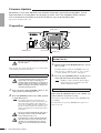
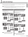
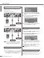
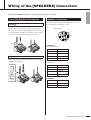
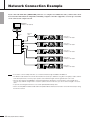
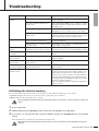
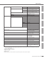
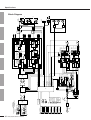
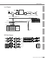
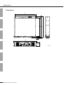
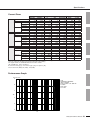
EN
DE
FR
ES
IT
RU
Explanation of Graphical Symbols
The lightning flash with arrowhead symbol
within an equilateral triangle is intended to
alert the user to the presence of uninsulated
“dangerous voltage” within the product’s
enclosure that may be of sufficient magnitude
to constitute a risk of electric shock to
persons.
C A U TI ON
RISK OF ELECTRIC SHOCK
DO NOT OPEN
CAUTION: TO REDUCE THE RISK OF
ELECTRIC SHOCK, DO NOT REMOVE
COVER (OR BACK). NO USER-SERVICEABLE
PARTS INSIDE. REFER SERVICING TO
QUALIFIED SERVICE PERSONNEL.
The exclamation point within an equilateral
triangle is intended to alert the user to the
presence of important operating and
maintenance (servicing) instructions in the
literature accompanying the product.
The above warning is located on the top of the unit.
IMPORTANT SAFETY INSTRUCTIONS
1
2
3
4
5
6
7
8
9
10
Read these instructions.
Keep these instructions.
Heed all warnings.
Follow all instructions.
Do not use this apparatus near water.
Clean only with dry cloth.
Do not block any ventilation openings. Install in
accordance with the manufacturer’s instructions.
Do not install near any heat sources such as
radiators, heat registers, stoves, or other apparatus
(including amplifiers) that produce heat.
Do not defeat the safety purpose of the polarized or
grounding-type plug. A polarized plug has two blades
with one wider than the other. A grounding type plug
has two blades and a third grounding prong. The wide
blade or the third prong are provided for your safety. If
the provided plug does not fit into your outlet, consult
an electrician for replacement of the obsolete outlet.
Protect the power cord from being walked on or
pinched particularly at plugs, convenience
receptacles, and the point where they exit from the
apparatus.
11
12
13
14
Only use attachments/accessories specified by the
manufacturer.
Use only with the cart, stand,
tripod, bracket, or table
specified by the manufacturer,
or sold with the apparatus.
When a cart is used, use
caution when moving the cart/
apparatus combination to
avoid injury from tip-over.
Unplug this apparatus during lightning storms or
when unused for long periods of time.
Refer all servicing to qualified service personnel.
Servicing is required when the apparatus has been
damaged in any way, such as power-supply cord or
plug is damaged, liquid has been spilled or objects
have fallen into the apparatus, the apparatus has
been exposed to rain or moisture, does not operate
normally, or has been dropped.
WARNING
TO REDUCE THE RISK OF FIRE OR ELECTRIC SHOCK, DO NOT EXPOSE THIS APPARATUS TO RAIN OR
MOISTURE.
(UL60065_03)
2
TX6n/5n/4n Owner’s Manual
FCC INFORMATION (U.S.A.)
1. IMPORTANT NOTICE: DO NOT MODIFY THIS
UNIT!
This product, when installed as indicated in the instructions
contained in this manual, meets FCC requirements. Modifications not expressly approved by Yamaha may void your
authority, granted by the FCC, to use the product.
2. IMPORTANT: When connecting this product to accessories and/or another product use only high quality shielded
cables. Cable/s supplied with this product MUST be used.
Follow all installation instructions. Failure to follow instructions could void your FCC authorization to use this product
in the USA.
3. NOTE: This product has been tested and found to comply
with the requirements listed in FCC Regulations, Part 15 for
Class “B” digital devices. Compliance with these requirements provides a reasonable level of assurance that your
use of this product in a residential environment will not result
in harmful interference with other electronic devices. This
equipment generates/uses radio frequencies and, if not
installed and used according to the instructions found in the
users manual, may cause interference harmful to the opera-
tion of other electronic devices. Compliance with FCC regulations does not guarantee that interference will not occur in
all installations. If this product is found to be the source of
interference, which can be determined by turning the unit
“OFF” and “ON”, please try to eliminate the problem by
using one of the following measures:
Relocate either this product or the device that is being
affected by the interference.
Utilize power outlets that are on different branch (circuit
breaker or fuse) circuits or install AC line filter/s.
In the case of radio or TV interference, relocate/reorient the
antenna. If the antenna lead-in is 300 ohm ribbon lead,
change the lead-in to co-axial type cable.
If these corrective measures do not produce satisfactory
results, please contact the local retailer authorized to distribute this type of product. If you can not locate the appropriate
retailer, please contact Yamaha Corporation of America,
Electronic Service Division, 6600 Orangethorpe Ave, Buena
Park, CA90620
The above statements apply ONLY to those products distributed by Yamaha Corporation of America or its subsidiaries.
* This applies only to products distributed by YAMAHA CORPORATION OF AMERICA.
COMPLIANCE INFORMATION STATEMENT
(DECLARATION OF
CONFORMITY PROCEDURE)
Responsible Party : Yamaha Corporation of America
Address : 6600 Orangethorpe Ave., Buena Park,
Calif. 90620
Telephone : 714-522-9011
Type of Equipment : Power Amplifier
Model Name : TX6n/TX5n/TX4n
(class B)
This product contains a battery that contains perchlorate
material.
Perchlorate Material—special handling may apply,
See www.dtsc.ca.gov/hazardouswaste/perchlorate.
* This applies only to products distributed by
YAMAHA CORPORATION OF AMERICA.
(Perchlorate)
This device complies with Part 15 of the FCC Rules.
Operation is subject to the following two conditions:
1) this device may not cause harmful interference, and
2) this device must accept any interference received including interference that may cause undesired operation.
See user manual instructions if interference to radio reception is suspected.
* This applies only to products distributed by
YAMAHA CORPORATION OF AMERICA.
(FCC DoC)
NEDERLAND / THE NETHERLANDS
ADVARSEL!
Lithiumbatteri—Eksplosionsfare ved fejlagtig håndtering.
Udskiftning må kun ske med batteri af samme fabrikat og
type. Levér det brugte batteri tilbage til leverandoren.
VARNING
Explosionsfara vid felaktigt batteribyte. Använd samma batterityp eller en ekvivalent typ som rekommenderas av apparattillverkaren. Kassera använt batteri enligt fabrikantens
instruktion.
VAROITUS
Paristo voi räjähtää, jos se on virheellisesti asennettu. Vaihda
paristo ainoastaan laitevalmistajan suosittelemaan tyyppiin.
Hävitä käytetty paristo valmistajan ohjeiden mukaisesti.
(lithium caution)
• Dit apparaat bevat een lithium batterij voor geheugen backup.
• This apparatus contains a lithium battery for memory backup.
• Raadpleeg uw leverancier over de verwijdering van de batterij op het moment dat u het apparaat ann het einde van
de levensduur of gelieve dan contact op te nemen met de
vertegenwoordiging van Yamaha in uw land.
• For the removal of the battery at the moment of the disposal at the end of life please consult your retailer or
Yamaha representative office in your country.
• Gooi de batterij niet weg, maar lever hem in als KCA.
• Do not throw away the battery. Instead, hand it in as small
chemical waste.
(lithium disposal)
TX6n/5n/4n Owner’s Manual
3
PRECAUTIONS
PLEASE READ CAREFULLY BEFORE PROCEEDING
* Please keep this manual in a safe place for future reference.
WARNING
Always follow the basic precautions listed below to avoid the possibility of serious injury or even death from
electrical shock, short-circuiting, damages, fire or other hazards. These precautions include, but are not limited
to, the following:
Power supply/Power cord
Water warning
• Only use the voltage specified as correct for the device. The required
voltage is printed on the name plate of the device.
• Do not place the power cord near heat sources such as heaters or radiators,
and do not excessively bend or otherwise damage the cord, place heavy
objects on it, or place it in a position where anyone could walk on, trip over,
or roll anything over it.
• Be sure to connect to an appropriate outlet with a protective grounding
connection. Improper grounding can result in electrical shock.
• Do not expose the device to rain, use it near water or in damp or wet
conditions, or place containers on it containing liquids which might spill
into any openings. If any liquid such as water seeps into the device, turn off
the power immediately and unplug the power cord from the AC outlet. Then
have the device inspected by qualified Yamaha service personnel.
• Never insert or remove an electric plug with wet hands.
If you notice any abnormality
Do not open
• Do not open the device or attempt to disassemble the internal parts or
modify them in any way. The device contains no user-serviceable parts. If it
should appear to be malfunctioning, discontinue use immediately and have
it inspected by qualified Yamaha service personnel.
• If the power cord or plug becomes frayed or damaged, or if there is a
sudden loss of sound during use of the device, or if any unusual smells or
smoke should appear to be caused by it, immediately turn off the power
switch, disconnect the electric plug from the outlet, and have the device
inspected by qualified Yamaha service personnel.
• If this device should be dropped or damaged, immediately turn off the
power switch, disconnect the electric plug from the outlet, and have the
device inspected by qualified Yamaha service personnel.
CAUTION
Always follow the basic precautions listed below to avoid the possibility of physical injury to you or others, or
damage to the device or other property. These precautions include, but are not limited to, the following:
Power supply/Power cord
• Remove the electric plug from the outlet when the device is not to be used
for extended periods of time, or during electrical storms.
• When removing the electric plug from the device or an outlet, always hold
the plug itself and not the cord. Pulling by the cord can damage it.
• Do not block the vents. This device has ventilation holes at the front/rear to
prevent the internal temperature from becoming too high. In particular, do
not place the device on its side or upside down. Inadequate ventilation can
result in overheating, possibly causing damage to the device(s), or even fire.
• Do not use the device in the vicinity of a TV, radio, stereo equipment,
mobile phone, or other electric devices. Doing so may result in noise, both
in the device itself and in the TV or radio next to it.
Location
Connections
• Before moving the device, remove all connected cables.
• When setting up the device, make sure that the AC outlet you are using is
easily accessible. If some trouble or malfunction occurs, immediately turn
off the power switch and disconnect the plug from the outlet. Even when the
power switch is turned off, electricity is still flowing to the product at the
minimum level. When you are not using the product for a long time, make
sure to unplug the power cord from the wall AC outlet.
• If the device is mounted in an EIA standard rack, carefully read the section
“Precautions when rack-mounting the unit” on page 6. Inadequate
ventilation can result in overheating, possibly causing damage to the
device(s), malfunction, or even fire.
• Do not use the device in a confined, poorly-ventilated location. If this
device is to be used in a small space other than an EIA-standard rack, make
sure that there is adequate space between the device and surrounding walls
or other devices: at least 10cm at the sides, 15cm behind and 40cm above.
Inadequate ventilation can result in overheating, possibly causing damage
to the device(s), or even fire.
• Do not expose the device to excessive dust or vibrations, or extreme cold
or heat (such as in direct sunlight, near a heater, or in a car during the day)
to prevent the possibility of panel disfiguration or damage to the internal
components.
• Before connecting the device to other devices, turn off the power for all
devices. Before turning the power on or off for all devices, set all volume
levels to minimum.
• Use only speaker cables for connecting speakers to the speaker jacks. Use
of other types of cables may result in fire.
• Do not place the device in a location where it may come into contact with
corrosive gases or salt air. Doing so may result in malfunction.
Maintenance
• Inspect the cooling fan air filter and clean it periodically (see the reference
manual (PDF file)). Dust and dirt can seriously degrade the effectiveness of
the cooling fan and result in malfunction or fire.
• Remove the power plug from the AC outlet when cleaning the device.
Handling caution
• When turning on the AC power in your audio system, always turn on the
device LAST, to avoid speaker damage. When turning the power off, the
device should be turned off FIRST for the same reason.
• Do not place the device in an unstable position where it might accidentally
fall over.
4
TX6n/5n/4n Owner’s Manual
(5)-6
1/2
• Condensation can occur in the device due to rapid, drastic changes in
ambient temperature – when the device is moved from one location to
another, or air conditioning is turned on or off, for example. Using the
device while condensation is present can cause damage. If there is reason
to believe that condensation might have occurred, leave the device for
several hours without turning on the power until the condensation has
completely dried out.
• Do not insert your fingers or hands in any gaps or openings on the device
(vents, ports, etc.).
• Avoid inserting or dropping foreign objects (paper, plastic, metal, etc.) into
any gaps or openings on the device (vents, ports, etc.) If this happens, turn
off the power immediately and unplug the power cord from the AC outlet.
Then have the device inspected by qualified Yamaha service personnel.
• Do not use the device or headphones for a long period of time at a high or
uncomfortable volume level, since this can cause permanent hearing loss.
If you experience any hearing loss or ringing in the ears, consult a
physician.
Backup battery
• This device has a built-in backup battery that maintains data in internal
memory even when the device’s power is switched off. The backup battery
will eventually become depleted, however, and when that happens the
contents of the internal memory will be lost.* To prevent loss of data be
sure to replace the backup battery before it becomes fully depleted. When
the remaining capacity of the backup battery becomes so low that it needs
to be replaced a “Critical Battery” or “No Battery” message will appear on
the display during operation or when the device is powered on. If either of
these messages appears do not turn off the power and immediately transfer
any data you want to save to a computer or other external storage device,
then have qualified Yamaha service personnel replace the backup battery.
The average life of the internal backup battery is approximately 5 years,
depending on operating conditions.
* Data items maintained in the internal memory by the backup battery are
as follows:
• Current scene parameters and number.
• Device parameters (Utility, AnalogInputMeter, SpeakerOut meter, etc.).
• Event log.
• Do not rest your weight on the device or place heavy objects on it, and
avoid use excessive force on the buttons, switches or connectors.
• Do not use this device for any purpose other than driving loudspeakers.
Data items other than those described above are stored in memory that
does not require backup power, and will be retained even if the backup
battery fails.
XLR-type connectors are wired as follows (IEC60268 standard): pin 1: ground, pin 2: hot (+), and pin 3: cold (-).
Use only Neutrik NL4 plugs for connecting Speakon connectors.
Yamaha cannot be held responsible for damage caused by improper use or modifications to the device, or data that is lost or destroyed.
Always turn the power off when the device is not in use.
Windows is a registered trademark of Microsoft® Corporation in the United
States and other countries.
The performance of components with moving contacts, such as switches,
volume controls, and connectors, deteriorates over time. Consult qualified
Yamaha service personnel about replacing defective components.
The bitmap fonts used in this device have been provided by and are the
property of Ricoh Co., Ltd.
The company names and product names in this manual are the trademarks or
registered trademarks of their respective companies.
Specifications and descriptions in this owner’s manual are for information
purposes only.
Yamaha Corp. reserves the right to change or modify products of
specifications at any time without prior notice. Since specifications,
equipment or options may not be the same in every locale, please check with
your Yamaha dealer.
European models
Purchaser/User Information specified in EN55103-1 and EN55103-2.
Inrush Current: 17A
Conforms to Environments: E1, E2, E3, E4
This mark indicates a dangerous electrically live terminal.
When connecting an external wire to this terminal, it is
necessary either to have “a person who have received
appropriate guidance on handling” make the connection or to
use leads or a cord that have been manufactured in such a way
that the connection can be made simply and without problem.
(hazardous)
IMPORTANT NOTICE FOR THE UNITED KINGDOM
Connecting the Plug and Cord
WARNING: THIS APPARATUS MUST BE EARTHED
IMPORTANT. The wires in this mains lead are coloured in accordance with the following code:
GREEN-AND-YELLOW : EARTH
BLUE
: NEUTRAL
BROWN
: LIVE
As the colours of the wires in the mains lead of this apparatus may not correspond with the coloured markings identifying the terminals in your plug proceed as follows:
The wire which is coloured GREEN-and-YELLOW must be connected to the terminal in the plug which is marked by the letter E or by
the safety earth symbol
or colored GREEN or GREEN-and-YELLOW.
The wire which is coloured BLUE must be connected to the terminal which is marked with the letter N or coloured BLACK.
The wire which is coloured BROWN must be connected to the terminal which is marked with the letter L or coloured RED.
• This applies only to products distributed by Yamaha Music U.K. Ltd.
(3 wires)
(5)-6
2/2
TX6n/5n/4n Owner’s Manual
5
Contents
Introduction ........................................................................................................7
Features................................................................................................................................... 7
About Setup ............................................................................................................................. 7
Related manuals and software ................................................................................................ 7
Firmware Updates ................................................................................................................... 8
Preparation .............................................................................................................................. 8
Basic Operation of the TXn...............................................................................9
Panel Operations ..................................................................................................................... 9
Operations that can be Performed from the Panel ................................................................ 10
Audio I/O Settings............................................................................................11
Wiring of the [SPEAKERS] Connectors.........................................................13
5-way Binding Post Connectors............................................................................................. 13
Speakon Connectors ............................................................................................................. 13
Network Connection Example ........................................................................14
Troubleshooting...............................................................................................15
Initializing the internal memory .............................................................................................. 15
Specifications...................................................................................................16
General Specifications........................................................................................................... 16
Block Diagram ....................................................................................................................... 18
Level Diagram........................................................................................................................ 19
DSP Block Diagram ............................................................................................................... 19
Dimensions ............................................................................................................................ 20
Current Draw ......................................................................................................................... 21
Performance Graph ............................................................................................................... 21
Included Accessories
• Owner’s Manual
• Two handles
• Four flat-head screws
• Euroblock connector (3P)
• Four Rubber feet
Precautions when rack-mounting the unit
Operation of this device is guaranteed for an environmental temperature range of 0 – 40°C. If you are
mounting only this device in an EIA standard rack, you may mount multiple units without leaving a space
between them. If you are mounting this device along with other types of device in an EIA standard rack,
the ambient temperature inside the rack may rise due to heat produced from the other devices, preventing this device from performing as designed. To ensure that heat does not build up inside this device,
you must observe the following conditions when mounting it in a rack.
• If you mount this device in a rack together with heat-generating devices such as power amps made by
other companies, you must leave 1U or more space between this device and other devices. You
should also install a ventilation panel in this space or leave it open to ensure adequate ventilation.
• Leave the back of the rack open, and allow 10 cm or more distance between the rack and the wall or
ceiling to ensure adequate ventilation. If you are unable to leave the back of the rack open, you must
install a commercially available fan kit or other forced air circulating system to the rack. If you have
installed a fan kit, there may be cases in which closing the back of the rack will provide better cooling.
For details, refer to the instructions that came with the rack system or fan kit.
6
TX6n/5n/4n Owner’s Manual
Introduction
Thank you for purchasing the Yamaha TX6n, TX5n, TX4n Power Amplifier. In order
to take full advantage of the TX6n/TX5n/TX4n’s (TXn) functionality and to ensure
trouble-free operation, please read this owner’s manual carefully before use. After you
have read the manual, keep it in a safe place for reference when needed.
Features
The TXn series are high audio quality, high efficiency, high reliability, low impedance drive power amplifiers that
utilize Yamaha’s famed DSP and digital audio networking technology.
■ Flexible support for analog and digital audio formats
In addition to two-channel analog input, these amplifiers come with an AES/EBU card installed in their MY card slot,
allowing digital signals to be input and output. Separately sold MY cards can be installed in this MY slot to support a variety of digital audio formats.
■ Monitor and control from Amp Editor
By connecting a computer in which the “Amp Editor” application software is installed, the computer can be used to monitor
the TXn units, or to control the TXn units such as switching the amplifier power’s Standby/On and mute status. This monitoring and control can also be performed from the panel of the TXn unit.
■ Versatile speaker processing
Since signal processors such as equalizer, delay, and crossover are built in, the use of external equipment can be minimized.
These can be controlled from the panel of the TXn unit or via Amp Editor. Speaker processor libraries created on the
Yamaha DME series or the SP2060 can also be used.
About Setup
■ Attaching the handles
You can attach the handles to the amplifier using the supplied flat-head screws.
Follow the steps below to attach the handles:
1. Remove the rack mount brackets.
2. Attach the handles to the amplifier by tightening the flat-head screws into the four screw holes for each handle.
3. Replace the rack mount brackets.
■ Adjusting the position in the rack
If there is insufficient space between the rear of the amplifier and the rack, you can adjust the position of the rack mount
brackets so that the front panel of the amplifier protrudes from the front of the rack by 22 mm.
Related manuals and software
This manual primarily explains how to set up the TXn at the time of installation. Manuals that contain detailed
explanations of the TXn and Amp Editor, as well as Amp Editor itself, can be downloaded from the following website.
http://www.yamahaproaudio.com/
• List of related manuals
TX6n/5n/4n Reference Manual
Provides a detailed explanation of the TXn’s panel operations, etc.
Amp Editor Installation Guide
Explains the installation and uninstallation procedures for Amp Editor.
Amp Editor Owner’s Manual
Explains how to use Amp Editor.
NOTE
• In order to view the downloaded manuals, Adobe Reader must be installed in your computer. If you don’t have Adobe
Reader, please access the Adobe Corporation’s website at the following URL, and download Adobe Reader (free of
charge).
http://www.adobe.com/
TX6n/5n/4n Owner’s Manual
7
Firmware Updates
The firmware version of the TXn itself can be checked from the TXn’s panel and from Amp Editor. You can
update the firmware via Amp Editor. For the update procedure, refer to the Amp Editor Owner’s Manual.
You can download the latest firmware from the “Downloads” page on the following website.
http://www.yamahaproaudio.com/
Preparation
[MUTE] buttons
[POWER] switch
Function buttons
[ENTER] button
[HOME] button
Connecting the AC Power Cable
• Be sure to turn all devices OFF before connecting
AC mains power.
CAUTION
Insert the plug into an AC outlet. Be sure to use an AC outlet
of the voltage specified for the device.
Turning the Power on and off
CAUTION
• To prevent the initial power-on surge from generating a large noise spike or damaging your
speaker system, turn the devices on in the following order: audio sources, mixer (such as M7CL or
PM5D), and finally power amplifiers. Reverse this
order when turning power off.
1. Press the front panel [POWER] switch to the
Switching the Power Status between
Standby and On
1. Hold down the panel [HOME] button for at least
three seconds.
The TXn’s display will show the HOME screen, and
then a message of “Turning power on: Are you sure?”
or “Going Standby: Are you sure?” will appear.
2. Press the panel [ENTER] button, and the power
status will switch between Standby and On.
NOTE
• Standby is a state in which the speaker output’s
power amp section is off (operation other than
speaker output will continue).
Switching Mute on/off
“ON” position to turn the power on.
2. Press the [POWER] switch to the “OFF” position
to turn off the power.
NOTE
CAUTION
CAUTION
8
• The settings at the time you powered-off are
remembered. When you turn on the power to the
TXn, it will start up with the same settings. You
can use the “Last Mem. Resume” setting to set up
the TXn so that at startup it will recall the scene
number selected before you turned off the power
to the device.
• Do not turn off the power while the upper part of
the display indicates “Do Not Turn Off!” Otherwise, a malfunction may occur.
• A small amount of current is flowing even when
the power switch is off. If you will not be using
this device for an extended period of time, be
sure to disconnect the power plug from the AC
outlet.
TX6n/5n/4n Owner’s Manual
Hold down the [MUTE] button of the channel you
want to mute for at least one second.
The channel’s output will be muted, and the [MUTE] indicator will light.
To switch mute off, press the [MUTE] button again for at
least one second.
Basic Operation of the TXn
Panel Operations
Encoder B
Function buttons
Encoder A
About the Display
[EXIT] button
[HOME] button
Adjusting the Attenuator
Shows an alert message if a problem occurs
or if a user-specified event occurs.
When the display shows the attenuator (i.e., in the HOME
screen or the METER screen), you can use encoders A and B
to adjust each channel’s attenuation.
NOTE
Shows the contents of the
selected screen.
[ENTER] button
• If the display shows a screen other than the HOME
screen or METER screen, encoders A and B are used
to set parameters.
Shows the names of the screens
assigned to the function buttons.
Switching Screens
Attenuator
By pressing a function button you can move to the screen
indicated above that button. By pressing the [HOME] button
you can move to the HOME screen. By pressing the [EXIT]
button you can move to the screen one level above.
Editing the Parameters
Use encoders A and B to move to the parameter that you
want to edit, and use encoder B to edit the value.
NOTE
Displaying the Meter
To display the meter, access the HOME screen and press the
left-most function button (METER). You can change the
meter type by using the left-most function button (PREV)
and the right-most function button (NEXT).
• When you edit a parameter in the UTILITY screen,
press the [ENTER] button to confirm it after you finish
editing. A parameter that has not been confirmed will
flash. If you move the cursor or move to a different
screen without confirming the parameter, your change
will not be applied.
Level meter
TX6n/5n/4n Owner’s Manual
9
Basic Operation of the TXn
Operations that can be Performed from the Panel
NOTE
• For details, refer to the TX6n/5n/4n Reference Manual.
Category
METER
UTILITY
MENU
Subcategory
Explanation
ANA INPUT VOLTAGE
Shows the input level from the analog input connectors.
SLOT INPUT VOLTAGE
Shows the input level from the slot.
SP OUTPUT VOLTAGE
Shows the output level from the [SPEAKERS] connectors.
SP OUTPUT POWER
Shows the output power from the [SPEAKERS] connectors.
SP OUTPUT IMPEDANCE
Shows the output impedance from the [SPEAKERS] connectors.
SLOT OUTPUT METER
Shows the output level to the slot.
THERMAL
Shows the heat sink temperature.
Device Setup
Makes settings to distinguish the amplifier on a network.
Word Clock Setup
Sets the word clock.
Information
Shows information about the amplifier.
Network Setup
Specifies the IP address and other settings for using the amplifier in a network.
LCD Setup
Specifies the display settings.
Front Panel Operation
Turns panel operation lock on/off.
Scene Setup
Makes scene* settings.
Misc Setup
Sets the amplifier’s internal clock, etc.
General
Sensitivity/Amp Gain
Sets the input sensitivity/gain.
Stereo/Bridge/Parallel
Specifies the amplifier’s mode (Stereo/Bridge/Parallel).
Attenation Link
Specifies whether attenuator operation will be linked between channels A
and B.
Input Redundancy
Specifies the redundant connection mode, etc.
Signal Path
Signal Chain
Calibration
Limiter
Makes settings for the equalizer, delay, crossover, and others that process
the audio signal. Speaker Processor libraries can also be recalled.
Analog Input Signal Chain
Makes settings for checking whether the audio signal is being correctly
input from the analog connectors.
Slot Input Signal Chain
Makes settings for checking whether the audio signal is being correctly
input from the slot.
Output Signal Chain
Makes settings for checking the status of output from the [SPEAKERS]
connectors.
Calibrate by Pilot Tone
Uses a pilot tone to measure the impedance of the connected speakers.
Calibrate by Program
Source
Uses an audio signal to measure the impedance of the connected speakers.
Voltage Limiter
Makes settings for the limiter.
Power Limiter
Limiter Gain Reduction
SCENE
Specifies whether the limiter will be linked between channels A and B.
Recall
Recalls a scene*.
Store
Stores a scene*.
Edit
Edits a scene*.
Clear
Clears a scene*.
*Scene..........The settings listed above, such as power Standby/On or mute (with the exception of UTILITY), are called a “scene”. By recalling a scene, the
saved settings can be immediately applied to the amplifiers.
10
TX6n/5n/4n Owner’s Manual
Audio I/O Settings
The TXn can be operated in one of three audio input/output modes: Stereo mode, Parallel mode, or Bridge mode.
Make audio input/output connections and settings as follows.
NOTE
• With the factory settings, if both analog and digital (input from the slot) signals are input simultaneously, the two signal will be
mixed and output. This setting can be changed from the panel of the TXn or via Amp Editor. For details on making this setting,
refer to “TX6n/5n/4n Reference Manual” or “Amp Editor Owner’s Manual.”
• Use 110-ohm AES/EBU digital cables for digital audio connections. Using analog cables may degrade the sonic quality.
Stereo Mode
Parallel Mode
Channels A and B (analog) or channels 1 and 2 (digital) will
operate independently in stereo.
5-way binding post connectors
The amplifier will operate as a two-channel monaural amp,
with the input signal of channel A (analog) or channel 1
(digital) as the source. Channel B (analog) and channel 2
(digital) will not be used.
5-way binding post connectors
–
+
+
–
–
Total speaker
impedance:
2–8Ω
Total speaker
impedance:
2–8Ω
+
+
–
Analog input
Total speaker
impedance:
2–8Ω
Digital input
Total speaker
impedance:
2–8Ω
Analog input
Digital input
Speakon connectors
Speakon connectors
Total speaker
impedance:
2–8Ω
Total speaker
impedance:
2–8Ω
Analog input
Digital input
Total speaker Total speaker
impedance: impedance:
2–8Ω 2–8Ω
Analog input
Digital input
NOTE
• Each of 5-way binding post connectors and Speakon
connectors are internally parallel-connected. When
using both connectors simultaneously, total speaker
impedance of each connector must be 4–16 Ω.
NOTE
• Each of 5-way binding post connectors and Speakon
connectors are internally parallel-connected. When
using both connectors simultaneously, total speaker
impedance of each connector must be 4–16 Ω.
TX6n/5n/4n Owner’s Manual
11
Audio I/O Settings
Bridge Mode
The amplifier will operate as a monaural high-power amp,
with the input signal of channel A (analog) or channel 1
(digital) as the source.
5-way binding post connectors
2. Use the encoder A to move the cursor (the blinking frame) to “General,” and press the [ENTER]
button.
3. Use the function buttons (PREV/NEXT) to access
Stereo/Bridge/Parallel screen.
–
+
Analog input
Total speaker
impedance:
4–16Ω
4. Use the encoder B to select the desired mode, and
press the [ENTER] button to confirm.
Digital input
Speakon connectors
Gain Setting
Set the amplifier gain.
1. Follow the steps 1 and 2 of the above “Mode Setting” to select “MENU” → “General.”
2. Use the function buttons (PREV/NEXT) to access
the Sensitivity/Amp Gain screen.
Analog input
Total speaker
impedance:
4–16Ω
Digital input
NOTE
• Each of 5-way binding post connectors and Speakon
connectors are internally parallel-connected. When
using both connectors simultaneously, total speaker
impedance of each connector must be 8–32 Ω.
3. Use encoder A to move the cursor to Amp Gain or
Sensitivity, and encoder B to edit the parameter
value.
4. If the parameter value is blinking, press the
[ENTER] button to confirm the value.
NOTE
Mode Setting
• Refer to the TX6n/5n/4n Reference Manual for details
on the gain.
Select the power amp mode according to the type of connections you’ve made.
1. Press the [HOME] button to access the HOME
screen, and press the third function button from
the left (MENU) to access the MENU screen.
12
TX6n/5n/4n Owner’s Manual
Word Clock Setting
If you want to input or output digital audio signals, you must
check the word clock settings as necessary. Refer to the
TX6n/5n/4n Reference Manual for details on how to check
these settings. The factory setting is “Auto Scan Mode: ON.”
Wiring of the [SPEAKERS] Connectors
Turn off the POWER switch before connecting external devices to the TXn.
5-way Binding Post Connectors
No Plugs
Speakon Connectors
Insert the Speakon cable plug (Neutrik NL4) into the connector, and turn it to the right to lock it.
Remove about 13mm of insulation from the end of each
speaker cable, and pass the bare wire through the holes in
the appropriate speaker terminals. Tighten the terminals to
securely clamp the wires. Be sure that the bare wire ends do
not jut out from the terminals and touch the chassis.
Neutric NL4 plugs
2–
2+
1+
1–
13mm
CHANNEL A
Stereo/Parallel Mode
Y-plugs
From above, insert the Y-plugs all the way into the opening,
and tighten the terminals.
Neutrik
Amplifier
1+
A+
1–
A–
2+
B+
2–
B–
Bridge Mode
Neutrik
Amplifier
1+
+
1–
2+
–
2–
0.25"
(6.3mm)
≤0.51"
(12.9mm)
CHANNEL B
Neutrik
Amplifier
1+
B+
1–
B–
TX6n/5n/4n Owner’s Manual
13
Network Connection Example
If you connect the TXn units’ [NETWORK] connector to a computer via an Ethernet cable, you’ll be able to monitor/control the TXn units from Amp Editor. Including computers and other equipment, a total of up to 253 units
can be connected in a single network.
Amp Editor
IP Address: 192.168.0.253
Ethernet
cable
Ethernet
cable
Device ID: 1
IP Address: 192.168.0.1
Device ID: 2
IP Address: 192.168.0.2
Network switch
Device ID: 3
IP Address: 192.168.0.3
Device ID: 4
IP Address: 192.168.0.4
Device ID: 5
IP Address: 192.168.0.5
NOTE
• If you wish to connect multiple TXn units, use a network switch that supports 100Base-TX/10Base-T.
• The Ethernet cable between the network switch and the TXn can be up to 100 meters long. Due to the quality of cables and network switch performance, however, proper operation at the maximum length cannot be guaranteed in some cases.
• Since the TXn supports Auto MDI/MDI-X, it will automatically detect whether the connected cable is of the straight type or
crossover type, and will configure itself to create the optimal connection. Therefore, you can use either a straight or crossover
cable.
• To prevent electromagnetic interference, use an STP (Shielded Twisted Pair) cable.
• Refer to the Amp Editor Installation Guide and the Amp Editor Owner’s Manual for information on the TXn initial setup for using
the TXn in a network.
14
TX6n/5n/4n Owner’s Manual
Troubleshooting
Symptom
No sound from the
speaker
Possible causes
Response
The cable is not connected properly.
Make the correct connections to the audio input jack and the
speaker output jack.
The gain or attenuator setting has lowered the level.
Gain is adjusted by the MENU screen → General → Sensitivity/Amp Gain. Attenuator is adjusted by turning the encoder in
the HOME screen.
The [MUTE] button is on.
If the front panel [MUTE] indicator is on, hold down the
[MUTE] button for one second or longer to cancel muting.
The protection circuit has operated, muting the output.
If the amplifier has overheated, clean the filter elements and
improve the ventilation around the amplifier. If the power supply has malfunctioned, contact your Yamaha dealer.
The word clock from the slot input is not
synchronized with the master clock.
Select the word clock from the slot as the master clock, or
turn Auto Scan Mode on.
Analog input level is exceeding the input
sensitivity setting.
Adjust MENU screen → General → Sensitivity/Amp Gain setting according to the input level.
An alert message is displayed
An amplifier malfunction or other alert event
related to the amplifier audio has occurred.
For details on the meaning of each alert message and the appropriate measures to take, refer to the Amp Editor Owner’s Manual.
Panel operations are not
accepted
The unit is locked.
Refer to “Front Panel Operation” in the TX6n/5n/4n Reference
Manual.
A scene can be saved
but not recalled
Scene Recall Enable is turned OFF.
Turn the UTILITY screen → Scene Setup → Scene Recall
Enable setting ON.
Library can be recalled,
but not saved
You cannot save library data from the
TXn front panel.
Save the library data from Amp Editor.
All scene data saved in
the TXn has disappeared
The power was turned off while the TXn’s
data was being saved.
If you saved the project in Amp Editor, synchronize from Amp
Editor to the TXn.
–
Recalling a scene 00 (default setting scene) will return all the
parameters other than those in the UTILITY settings to their
default values. The TXn allows you to edit a wide variety of
parameters, but can also be used as an analog amplifier by
returning to the default parameter values. Default values of
the main parameters are STEREO for amplifier mode, 26dB
for gain, and -∞dB for attenuation.
Refer to the TX6n/5n/4n Reference Manual for detailed information on scenes.
Noise from the speaker
To return to the default
parameter values
Initializing the internal memory
You can initialize the amp’s internal memory. As desired, you can initialize the following two types of data.
• User Data: Initialize all user data except for the event log and speaker processor library.
• Library: Initialize only the speaker processor library.
• When you initialize the internal memory, the settings that had been stored will be lost. Use the following procedure with
caution.
CAUTION
1. Power-off the TXn.
2. While holding down the [HOME] key, turn on the power; the Initialize screen will appear.
3. Use encoder A to select the data that you want to initialize, and press the [ENTER] button to execute initialization.
When initialization is completed, the amp will automatically restart.
• During initialization, the display will show the message “Do not turn off!” Never turn off the amp while this message is
displayed.
CAUTION
TX6n/5n/4n Owner’s Manual
15
Specifications
General Specifications
TX6n
Output
Power
1kHz,
THD + N = 1%
20ms burst
TX5n
TX4n
120V
230V (*1)
120V
230V (*1)
120V
230V (*1)
8Ω per channel
1800W
1800W
1300W
1300W
1100W
1100W
4Ω per channel
3000W
3000W
2200W
2300W
1900W
2000W
2Ω per channel
2750W
2750W
2500W
2500W
2200W
2200W
8Ω bridge
6000W
6000W
4400W
4600W
3800W
4000W
4Ω bridge
5500W
5500W
5000W
5000W
4400W
4400W
2Ω per channel
4100W
4120W
3480W
3600W
2990W
3050W
4Ω bridge
8200W
8240W
6960W
7200W
5980W
6100W
STEREO mode :
100V line, 1250W / 8Ω
BRIDGE mode :
200V line, 2500W / 16Ω
Constant voltage line
—
—
Voltage
Gain
RL = 8Ω
Analog input to speaker output
43.8dB – 19.8dB,
0.1dB step
43.8dB – 19.8dB,
0.1dB step
43.8dB – 19.8dB,
0.1dB step
Input
Sensitivity
RL = 8Ω
Analog input to speaker output
0.0dBu – 24.0dBu,
0.1dB step
-1.4dBu – 22.6dBu,
0.1dB step
-2.6dBu – 21.4dBu,
0.1dB step
SN Ratio
20Hz – 20kHz,
DIN AUDIO
Analog input to
speaker output (Input
sensitivity = +24dBu)
103dB
102dB
101dB
AES/EBU input to
speaker output
108dB
107dB
106dB
All Models
THD + N
1kHz, half power
RL = 4Ω, 8Ω
≤0.2%
RL = 2Ω
≤0.4%
Intermodulation Distortion
60Hz : 7kHz, 4 : 1, Half power (*2), RL = 4Ω, 8Ω
≤0.25%
Frequency Response
RL = 8Ω, Po = 1W, 20Hz – 20kHz
+0dB, -1.0dB
Channel Separation
Att. max, half power (*3), RL = 8Ω, 1kHz, input 600Ω shunt
65dB
Damping Factor
RL = 8Ω, ≤100Hz
>300
Maximum Input Level
+24dBu (*4)
Attenuation
0dB – -80dB, -∞dB (0.5dB step)
Input Impedance
20kΩ (balanced), 10kΩ (unbalanced)
A/D, D/A Converter
24-bit
Sampling Frequency
96k, 88.2k, 48k, 44.1kHz
Signal Processing
Signal Delay
32bit DSP
Analog input to speaker output
AES/EBU input to speaker output
Controls
16
fs = 96kHz
729us
fs = 48kHz
1.13ms
fs = 96kHz
708us
fs = 48kHz
1.02ms
Analog input to AES/EBU output
fs = 96kHz
396us
fs = 48kHz
583us
AES/EBU input to AES/EBU output
fs = 96kHz
365us
fs = 48kHz
479us
AES/EBU input to AES/EBU though output
0.04us
Front panel
POWER switch (push ON / push OFF),
Rotary encoder x 2,
Function button x 4, HOME button x 1,
EXIT button x 1, ENTER button x 1,
Mute button x 2
TX6n/5n/4n Owner’s Manual
Specifications
Connectors
Analog input
AES/EBU input/output
In
XLR-3-32 type x 2
In
XLR-3-31 type x 1
(2 channels, 24-bit 96kHz – 44.1kHz)
Thru
XLR-3-32 type x 1 (2 channels)
Out
XLR-3-32 type x 1
(2 channels, 24-bit 96kHz – 44.1kHz)
Neutrik® Speakon® NL4 x 2,
5-way binding post x 2 pairs
Speaker output
Indicators
XLR-3-31 type x 2
Thru
Ethernet
RJ45 x 1
Fault output
Euroblock connector (3P) x 1
LCD
160 x 64 Full dot type
LED
POWER
x 1 (Orange)
PARALLEL
x 1 (Orange)
BRIDGE
x 1 (Green)
PROTECTION
x 1 (Red)
NETWORK
x 1 (Green)
IDENTIFY
x 1 (Blue)
SIGNAL
x 1 (Green)
CLIP
x 1 (Red)
ALERT
x 1 (Orange)
MUTE
Load Protection
x 1 (White)
STANDBY
x 2 (Red)
POWER switch ON / OFF mute
DC-fault : Amplifier shuts down automatically
Clip limiting : THD ≥ 0.5%
Amplifier Protection
Thermal : Mute the output (heatsink temp ≥
90˚C) (return automatically.)
Power Supply Protection
Thermal : Amplifier shuts down automatically.
(heatsink temp ≥ 100˚C)
VI limiter(RL ≤ 1Ω) : Limit the output
Cooling
Variable speed fan : x 2
Power Requirements
U.S./Canada: 120V, 60Hz
Korea: 220V, 60Hz
China: 220V, 50Hz
Other: 220V-240V, 50/60Hz
Power Consumption
TX6n: 1800W, TX5n: 1600W, TX4n: 1500W
Power Cord Length
1.5m
Dimensions (W x H x D)
480mm x 88mm x 461mm;
18-7/8" x 3-7/16" x 18-1/8"
Weight
16kg; 35.3lbs
Operation free-air Temperature Range
0˚C to +40˚C
Storage Temperature Range
-20˚C to +60˚C
Accessory
Handle x 2 (with flat-head screw x 4), Euroblock connector (3P) x 1, Rubber Feet x 4,
Owner’s Manual
(*1) Output power depends on the power supply voltage. These figures are based on 230V.
If the power supply voltage is 220V, output power will be about 8% less than the power shown in the table. Output power will be about
7% more in case of 240V.
(*2) 1/8 power = 9dB below rated power
(*3) Half power = 3dB below rated power
(*4) 0dBu = 0.775Vrms
Trademarks notice :
Neutrik®, Speakon® are used for information only and are the property of their respective companies.
TX6n/5n/4n Owner’s Manual
17
TX6n/5n/4n Owner’s Manual
CHB
CHA
CHB
CHA
CHB
CHA
CHB
CHA
FG
FG
SIGNAL(GR)
CLIP(RE)
ALERT(OR)
MUTE(RE)
STANDBY(OR)
POWER(WH)
PARALLEL(OR)
BRIDGE(GR)
PROTECTION(RE)
NETWORK(GR)
IDENTIFY(BL)
Channel B
Channel A
ANALOG AUDIO
BA
LCD Module
Volume
Control
CHB
CHA
CHB
PowerSW
ENTER
EXIT
HOME
FUNCTION
MUTE
ENCODER
CHA
EMI
FILTER
GAIN
–10.8dB
BA
GAIN
–10.8dB
ANALOG AUDIO Signals
[+13.2dBu] MAX
RELAY
RELAY
+24
DSP
SENSE_U
CPU
SENSE_I
RELAY DRIVE
CIRCUIT
VOLTAGE
SENCE
–15VA
+15VA
AC VOLTAGE
DETECT
PSW_DETECT
MAINS
TEMP_PS
FAN_MONITOR
RELAY_PS
SHUTDOWN_PS
FAN_CONTROL
FAULT_OUTPUT
TEMP_PA
RELAY_PA
D/A
SUB TRANSFORMER
SWITCHING
CONTROLLER
PSW
DETECT
CLIP
RELAY DRIVE
CIRCUIT
+24
A/D
SIO
+3.3VD
–5VA
+5VA
TEMPERATURE
SENSOR
+15VA
+15VA
TEMPERATURE
SENSOR
PS HEAT SINK
150Apeak
OVERCURRENT
DETECTOR
PS HEAT SINK
150Apeak
+90°C
+90°C
SHUTDOWN
CIRCUIT
(LATCH)
SWITCHING
DRIVER
SHUTDOWN
CIRCUIT
(LATCH)
CONTROL
IC
SWITCHING
DRIVER
Clip
Detector
Differential
Amplifier
Stage
OVERCURRENT
DETECTOR
Temperature
sensor
Negative
Feedback
Loop
Network
+3.3D
DGND
Clip
Detector
Total Gain: +37dB
Temperature
sensor
+5D
–5A
–15A
AGND
+15A
+5A
+24A_A
Volume
Control
Negative
Feedback
Loop
Network
Differential
Amplifier
Stage
Total Gain: +37dB
FB
18
FB
ANALOG AUDIO INPUTs
[+24dBu] MAX
ASO
Limitter
ASO
Limitter
MAIN TRANSFORMER CHB
FAN CONTROL
CIRCUIT
+E_2+15V
+E_2
–E_2
–E+2+15V
+B_2
PGND_2
–B_2
PHASE SHIFT SWITCHING
FAN CONTROL
CIRCUIT
+E_1+15V
+E_1
–E_1
–E_1+15V
MAIN TRANSFORMER CHA
+B_1
PGND_1
–B_1
Protection
Relay
Voltage
Amplifier
Stage
Protection
Relay
Voltage
Amplifier
Stage
EEEngine
Voltage
Limitter
Voltage
Limitter
Voltage
Limitter
Voltage
Limitter
FAN(R)
FAN(L)
EEEngine(–B)
Current
Sensing
Power
Amplifier
Stage
EEEngine(+B)
Current
Sensing
Power
Amplifier
Stage
EEEngine
–B_2
–E_2+15
–E_2
PGND_2
+E_2
+E_2+15
+B_2
–B_1
–E_1
PGND_1
–E_1+15
+E_1
+E_1+15
+B_1
Voltage
Sensor
Voltage
Sensor
MY SLOT
Current
Sensor
Current
Sensor
DIT
DIR
FAULT
OUTPUT
2+
1+
2+
1+
2–
2–
OUT
THRU
IN
AES EBU
NETWORK
1–
1–
OUTPUT
(SPEAKERS)
CH B
CH A
Specifications
Block Diagram
Specifications
Level Diagram
DIGITAL
INPUT
ANALOG
INPUT
ATTENUATOR
DSP
INPUT
AMP
AD
POWER
AMP
DA
GAIN
ATTENUATOR (all models): 0.0 to -80.0, -∞dB (0.5dB step)
GAIN (all models): 19.8 to 43.8dB (0.1dB step)
32.0dB (default)
GAIN
TX6n Clips (43.8dBu) TX5n Clips
TX4n Clips
GAIN: 19.8dB (min.)
+24.0dBu
0dBFS (digital max.)
ATT: 0.0dB
Maximum Output Power
43.8dBu (1800W/8Ω)
42.4dBu (1300W/8Ω)
41.2dBu (1000W/8Ω)
Model
TX6n
TX5n
TX4n
GAIN: 32.0dB (default)
+11.8dBu (TX6n)
Model
Input Sensitivity
TX6n
+24.0 to 0dBu (8Ω)
default: +11.8dBu
TX5n
+22.6 to -1.4dBu (8Ω)
default: +10.4dBu
TX4n
+21.4 to -2.6dBu (8Ω)
default: +9.2dBu
ATTENUATOR
GAIN: 43.8dB (max.)
0dBu (TX6n)
GAIN
19.8 to 43.8dB
default: 32.0dB
ATT: -∞dB
DSP Block Diagram
Redundancy
[Analog
Input A]
ADC
ADC
[Speaker Processor]
Pol.
PEQ
Level
Delay
Pol.
XOver
Delay
PEQ Level MUTE Limiter
MUTE
Protection
DAC
Att.
Amp [Speaker
Output A]
3
5
Gain/
Sens.
[Analog
Input B]
ADC
[Speaker Processor]
ADC
PEQ
Pol.
Delay
Level
Pol.
XOver
Delay
PEQ Level MUTE Limiter
MUTE
Protection
DAC
Att.
Amp [Speaker
Output B]
4
6
Matrix
Mixer
1
Pol.
1
OSC
7
2
3
Slot
Input
Gain
4
Router
5
Pol.
Router
Slot
Output
6
2
OSC
7
8
8
TX6n/5n/4n Owner’s Manual
19
Specifications
Dimensions
432
415
17
461
405
41
10
30
429
88
480
Unit: mm
20
TX6n/5n/4n Owner’s Manual
Specifications
Current Draw
TX6n
standby
idle
1/8 power
1/3 power
TX5n
standby
idle
1/8 power
1/3 power
TX4n
standby
idle
1/8 power
1/3 power
8ohms/ch
4ohms/ch
2ohms/ch
8ohms/ch
4ohms/ch
2ohms/ch
Line Current (A)
100/120V
230/240V
0.36
0.20
1.6
0.88
13.7
7.5
19.2
10.6
22.0
12.1
26.9
14.8
40.4
22.2
44.7
24.5
19
75
833
1250
1432
1828
2910
3216
Power (W)
Out
0
0
425
688
688
1133
1833
1833
Dissipated
19
75
408
563
745
695
1077
1383
In
Thermal Dissipation
Btu/h
kcal/h
65
16
256
605
1390
351
1920
484
2540
641
2370
597
3670
926
4720
1190
8ohms/ch
4ohms/ch
2ohms/ch
8ohms/ch
4ohms/ch
2ohms/ch
0.36
1.6
10.4
14.7
20.0
20.6
30.9
40.6
0.20
0.9
5.7
8.1
11.0
11.3
17.0
22.3
19
75
637
955
1302
1398
2222
2924
0
0
325
525
625
867
1400
1667
19
75
312
430
677
531
822
1257
65
256
1070
1470
2310
1810
2810
4290
16
65
269
369
582
457
707
1080
8ohms/ch
4ohms/ch
2ohms/ch
8ohms/ch
4ohms/ch
2ohms/ch
0.36
1.6
8.0
12.2
17.6
15.8
25.7
35.7
0.20
0.9
4.4
6.7
9.7
8.7
14.1
19.6
19
75
490
795
1146
1075
1852
2573
0
0
250
438
550
667
1167
1467
19
75
240
358
596
409
685
1106
65
256
820
1220
2030
1390
2340
3780
16
65
207
308
512
351
589
952
1/8 power is typical of program material with occasional clipping. Refer to these figures for most applications.
1/3 power represents program material with extremely heavy clipping.
Test signal: Pink Noise, bandwidth limited from 22Hz to 22kHz
1W = 0.860kcal/h, 1BTU = 0.252kcal
Note that Line Voltage [V] x Line Current [A] = [VA], not equals to [W].
Inrush current: 8A (100V), 9A (120V), 17A (240V)
Performance Graph
Audio Precision
+2
TX6n
FREQUENCY RESPONSE
INPUT : ANALOG
OUTPUT LOAD : 8ohm 0dBr=1W
Fs=96kHz
GAIN : 32dB
ATT : MAX
+0
-2
dBr
-4
-6
-8
10
20
50
100
200
500
1k
Hz
2k
5k
10k
20k
100k
TX6n/5n/4n Owner’s Manual
21
Information for Users on Collection and Disposal of Old Equipment
EN
This symbol on the products, packaging, and/or accompanying documents means that used electrical and electronic products should
not be mixed with general household waste.
For proper treatment, recovery and recycling of old products, please take them to applicable collection points, in accordance with your
national legislation and the Directives 2002/96/EC.
By disposing of these products correctly, you will help to save valuable resources and prevent any potential negative effects on human
health and the environment which could otherwise arise from inappropriate waste handling.
For more information about collection and recycling of old products, please contact your local municipality, your waste disposal service
or the point of sale where you purchased the items.
[For business users in the European Union]
If you wish to discard electrical and electronic equipment, please contact your dealer or supplier for further information.
[Information on Disposal in other Countries outside the European Union]
This symbol is only valid in the European Union. If you wish to discard these items, please contact your local authorities or dealer and
ask for the correct method of disposal.
DE
Verbraucherinformation zur Sammlung und Entsorgung alter Elektrogeräte
Befindet sich dieses Symbol auf den Produkten, der Verpackung und/oder beiliegenden Unterlagen, so sollten benutzte elektrische
Geräte nicht mit dem normalen Haushaltsabfall entsorgt werden.
In Übereinstimmung mit Ihren nationalen Bestimmungen und den Richtlinien 2002/96/EC, bringen Sie alte Geräte bitte zur fachgerechten Entsorgung, Wiederaufbereitung und Wiederverwendung zu den entsprechenden Sammelstellen.
Durch die fachgerechte Entsorgung der Elektrogeräte helfen Sie, wertvolle Ressourcen zu schützen und verhindern mögliche negative Auswirkungen auf die menschliche Gesundheit und die Umwelt, die andernfalls durch unsachgerechte Müllentsorgung auftreten könnten.
Für weitere Informationen zum Sammeln und Wiederaufbereiten alter Elektrogeräte, kontaktieren Sie bitte Ihre örtliche Stadt- oder
Gemeindeverwaltung, Ihren Abfallentsorgungsdienst oder die Verkaufsstelle der Artikel.
[Information für geschäftliche Anwender in der Europäischen Union]
Wenn Sie Elektrogeräte ausrangieren möchten, kontaktieren Sie bitte Ihren Händler oder Zulieferer für weitere Informationen.
[Entsorgungsinformation für Länder außerhalb der Europäischen Union]
Dieses Symbol gilt nur innerhalb der Europäischen Union. Wenn Sie solche Artikel ausrangieren möchten, kontaktieren Sie bitte Ihre
örtlichen Behörden oder Ihren Händler und fragen Sie nach der sachgerechten Entsorgungsmethode.
FR
Information concernant la Collecte et le Traitement des déchets d’équipements électriques et électroniques
Le symbole sur les produits, l’emballage et/ou les documents joints signifie que les produits électriques ou électroniques usagés ne doivent pas être mélangés avec les déchets domestiques habituels.
Pour un traitement, une récupération et un recyclage appropriés des déchets d’équipements électriques et électroniques, veuillez les
déposer aux points de collecte prévus à cet effet, conformément à la réglementation nationale et aux Directives 2002/96/EC.
En vous débarrassant correctement des déchets d’équipements électriques et électroniques, vous contribuerez à la sauvegarde de
précieuses ressources et à la prévention de potentiels effets négatifs sur la santé humaine qui pourraient advenir lors d’un traitement
inapproprié des déchets.
Pour plus d’informations à propos de la collecte et du recyclage des déchets d’équipements électriques et électroniques, veuillez contacter votre municipalité, votre service de traitement des déchets ou le point de vente où vous avez acheté les produits.
[Pour les professionnels dans l’Union Européenne]
Si vous souhaitez vous débarrasser des déchets d’équipements électriques et électroniques veuillez contacter votre vendeur ou fournisseur pour plus d’informations.
[Information sur le traitement dans d’autres pays en dehors de l’Union Européenne]
Ce symbole est seulement valables dans l’Union Européenne. Si vous souhaitez vous débarrasser de déchets d’équipements électriques et électroniques, veuillez contacter les autorités locales ou votre fournisseur et demander la méthode de traitement appropriée.
ES
Información para Usuarios sobre Recolección y Disposición de Equipamiento Viejo
Este símbolo en los productos, embalaje, y/o documentación que se acompañe significa que los productos electrónicos y eléctricos
usados no deben ser mezclados con desechos hogareños corrientes.
Para el tratamiento, recuperación y reciclado apropiado de los productos viejos, por favor llévelos a puntos de recolección aplicables,
de acuerdo a su legislación nacional y las directivas 2002/96/EC.
Al disponer de estos productos correctamente, ayudará a ahorrar recursos valiosos y a prevenir cualquier potencial efecto negativo
sobre la salud humana y el medio ambiente, el cual podría surgir de un inapropiado manejo de los desechos.
Para mayor información sobre recolección y reciclado de productos viejos, por favor contacte a su municipio local, su servicio de gestión de residuos o el punto de venta en el cual usted adquirió los artículos.
[Para usuarios de negocios en la Unión Europea]
Si usted desea deshacerse de equipamiento eléctrico y electrónico, por favor contacte a su vendedor o proveedor para mayor información.
[Información sobre la Disposición en otros países fuera de la Unión Europea]
Este símbolo sólo es válidos en la Unión Europea. Si desea deshacerse de estos artículos, por favor contacte a sus autoridades locales y pregunte por el método correcto de disposición.
IT
Informazioni per gli utenti sulla raccolta e lo smaltimento di vecchia attrezzatura
Questo simbolo sui prodotti, sull’imballaggio, e/o sui documenti che li accompagnano significa che i prodotti elettriche e elettroniche
non dovrebbero essere mischiati con i rifiuti domestici generici.
Per il trattamento, recupero e riciclaggio appropriati di vecchi prodotti, li porti, prego, ai punti di raccolta appropriati, in accordo con la
Sua legislazione nazionale e le direttive 2002/96/CE.
Smaltendo correttamente questi prodotti, Lei aiuterà a salvare risorse preziose e a prevenire alcuni potenziali effetti negativi sulla salute
umana e l’ambiente, che altrimenti potrebbero sorgere dal trattamento improprio dei rifiuti.
Per ulteriori informazioni sulla raccolta e il riciclaggio di vecchi prodotti, prego contatti la Sua amministrazione comunale locale, il Suo
servizio di smaltimento dei rifiuti o il punto vendita dove Lei ha acquistato gli articoli.
[Per utenti imprenditori dell’Unione europea]
Se Lei desidera disfarsi di attrezzatura elettrica ed elettronica, prego contatti il Suo rivenditore o fornitore per ulteriori informazioni.
[Informazioni sullo smaltimento negli altri Paesi al di fuori dell’Unione europea]
Questo simbolo è validi solamente nell’Unione europea. Se Lei desidera disfarsi di questi articoli, prego contatti le Sue autorità locali o
il rivenditore e richieda la corretta modalità di smaltimento.
For details of products, please contact your nearest Yamaha
representative or the authorized distributor listed below.
Pour plus de détails sur les produits, veuillez-vous adresser à Yamaha ou
au distributeur le plus proche de vous figurant dans la liste suivante.
NORTH AMERICA
CANADA
Yamaha Canada Music Ltd.
135 Milner Avenue, Scarborough, Ontario,
M1S 3R1, Canada
Tel: 416-298-1311
U.S.A.
Yamaha Corporation of America
6600 Orangethorpe Ave., Buena Park, Calif. 90620,
U.S.A.
Tel: 714-522-9011
CENTRAL & SOUTH AMERICA
MEXICO
Yamaha de México S.A. de C.V.
Calz. Javier Rojo Gómez #1149,
Col. Guadalupe del Moral
C.P. 09300, México, D.F., México
Tel: 55-5804-0600
Die Einzelheiten zu Produkten sind bei Ihrer unten aufgeführten
Niederlassung und bei Yamaha Vertragshändlern in den jeweiligen
Bestimmungsländern erhältlich.
Para detalles sobre productos, contacte su tienda Yamaha más cercana
o el distribuidor autorizado que se lista debajo.
ASIA
POLAND
Yamaha Music Europe GmbH
Branch Sp.z o.o. Oddzial w Polsce
ul. 17 Stycznia 56, PL-02-146 Warszawa, Poland
Tel: 022-868-07-57
THE NETHERLANDS/
BELGIUM/LUXEMBOURG
Yamaha Music Europe Branch Benelux
Clarissenhof 5-b, 4133 AB Vianen, The Netherlands
Tel: 0347-358 040
FRANCE
Yamaha Musique France
BP 70-77312 Marne-la-Vallée Cedex 2, France
Tel: 01-64-61-4000
ITALY
Yamaha Musica Italia S.P.A.
Combo Division
Viale Italia 88, 20020 Lainate (Milano), Italy
Tel: 02-935-771
SPAIN/PORTUGAL
BRAZIL
Yamaha Musical do Brasil Ltda.
Rua Joaquim Floriano, 913 - 4' andar, Itaim Bibi,
CEP 04534-013 Sao Paulo, SP. BRAZIL
Tel: 011-3704-1377
Yamaha Música Ibérica, S.A.
Ctra. de la Coruna km. 17, 200, 28230
Las Rozas (Madrid), Spain
Tel: 91-639-8888
SWEDEN
ARGENTINA
Yamaha Music Latin America, S.A.
Sucursal de Argentina
Olga Cossettini 1553, Piso 4 Norte
Madero Este-C1107CEK
Buenos Aires, Argentina
Tel: 011-4119-7000
PANAMA AND OTHER LATIN
AMERICAN COUNTRIES/
CARIBBEAN COUNTRIES
Yamaha Music Latin America, S.A.
Torre Banco General, Piso 7, Urbanización Marbella,
Calle 47 y Aquilino de la Guardia,
Ciudad de Panamá, Panamá
Tel: +507-269-5311
EUROPE
THE UNITED KINGDOM
Yamaha Music U.K. Ltd.
Sherbourne Drive, Tilbrook, Milton Keynes,
MK7 8BL, England
Tel: 01908-366700
Yamaha Scandinavia AB
J. A. Wettergrens Gata 1, Box 30053
S-400 43 Göteborg, Sweden
Tel: 031 89 34 00
DENMARK
YS Copenhagen Liaison Office
Generatorvej 6A, DK-2730 Herlev, Denmark
Tel: 44 92 49 00
NORWAY
Norsk filial av Yamaha Scandinavia AB
Grini Næringspark 1, N-1345 Østerås, Norway
Tel: 67 16 77 70
SWITZERLAND/LIECHTENSTEIN
Yamaha Music Europe GmbH
Branch Switzerland in Zürich
Seefeldstrasse 94, 8008 Zürich, Switzerland
Tel: 01-383 3990
AUSTRIA
Yamaha Music Europe GmbH Branch Austria
Schleiergasse 20, A-1100 Wien, Austria
Tel: 01-60203900
CZECH REPUBLIC/SLOVAKIA/
HUNGARY/SLOVENIA
Yamaha Music Europe GmbH Branch Austria
Schleiergasse 20, A-1100 Wien, Austria
Tel: 01-602039025
Yamaha Music & Electronics (China) Co.,Ltd.
2F, Yunhedasha, 1818 Xinzha-lu, Jingan-qu,
Shanghai, China
Tel: 021-6247-2211
INDIA
Yamaha Music India Pvt. Ltd.
5F Ambience Corporate Tower Ambience Mall Complex
Ambience Island, NH-8, Gurgaon-122001, Haryana, India
Tel: 0124-466-5551
INDONESIA
PT. Yamaha Music Indonesia (Distributor)
PT. Nusantik
Gedung Yamaha Music Center, Jalan Jend. Gatot
Subroto Kav. 4, Jakarta 12930, Indonesia
Tel: 21-520-2577
KOREA
Yamaha Music Korea Ltd.
8F, 9F, Dongsung Bldg. 158-9 Samsung-Dong,
Kangnam-Gu, Seoul, Korea
Tel: 080-004-0022
MALAYSIA
Yamaha Music Malaysia, Sdn., Bhd.
Lot 8, Jalan Perbandaran, 47301 Kelana Jaya,
Petaling Jaya, Selangor, Malaysia
Tel: 3-78030900
SINGAPORE
Yamaha Music Asia Pte., Ltd.
#03-11 A-Z Building
140 Paya Lebor Road, Singapore 409015
Tel: 747-4374
TAIWAN
Yamaha KHS Music Co., Ltd.
3F, #6, Sec.2, Nan Jing E. Rd. Taipei.
Taiwan 104, R.O.C.
Tel: 02-2511-8688
THAILAND
RUSSIA
Yamaha Music (Russia)
Office 4015, entrance 2, 21/5 Kuznetskii
Most street, Moscow, 107996, Russia
Tel: 495 626 0660
OTHER EUROPEAN COUNTRIES
Yamaha Music Europe GmbH
Siemensstraße 22-34, 25462 Rellingen, Germany
Tel: +49-4101-3030
GERMANY
Yamaha Music Europe GmbH
Siemensstraße 22-34, 25462 Rellingen, Germany
Tel: 04101-3030
THE PEOPLE’S REPUBLIC OF CHINA
AFRICA
Yamaha Corporation,
Asia-Pacific Music Marketing Group
Nakazawa-cho 10-1, Naka-ku, Hamamatsu,
Japan 430-8650
Tel: +81-53-460-2313
MIDDLE EAST
TURKEY/CYPRUS
Yamaha Music Europe GmbH
Siemensstraße 22-34, 25462 Rellingen, Germany
Tel: 04101-3030
OTHER COUNTRIES
Yamaha Music Gulf FZE
LOB 16-513, P.O.Box 17328, Jubel Ali,
Dubai, United Arab Emirates
Tel: +971-4-881-5868
Siam Music Yamaha Co., Ltd.
4, 6, 15 and 16th floor, Siam Motors Building,
891/1 Rama 1 Road, Wangmai,
Pathumwan, Bangkok 10330, Thailand
Tel: 02-215-2626
OTHER ASIAN COUNTRIES
Yamaha Corporation,
Asia-Pacific Music Marketing Group
Nakazawa-cho 10-1, Naka-ku, Hamamatsu,
Japan 430-8650
Tel: +81-53-460-2317
OCEANIA
AUSTRALIA
Yamaha Music Australia Pty. Ltd.
Level 1, 99 Queensbridge Street, Southbank,
Victoria 3006, Australia
Tel: 3-9693-5111
COUNTRIES AND TRUST
TERRITORIES IN PACIFIC OCEAN
Yamaha Corporation,
Asia-Pacific Music Marketing Group
Nakazawa-cho 10-1, Naka-ku, Hamamatsu,
Japan 430-8650
Tel: +81-53-460-2313
HEAD OFFICE Yamaha Corporation, Pro Audio & Digital Musical Instrument Division
Nakazawa-cho 10-1, Naka-ku, Hamamatsu, Japan 430-8650
Tel: +81-53-460-2441
PA24
Yamaha Pro Audio global web site:
http://www.yamahaproaudio.com/
Yamaha Manual Library
http://www.yamaha.co.jp/manual/
C.S.G., Pro Audio Division
© 2009-2011 Yamaha Corporation
WP58530 102POZCx.x-03D0
Printed in Indonesia


![3URIHVVLRQDO HTXDOL]HU [ EDQG](http://vs1.manualzilla.com/store/data/006777932_1-770431aef94eb6d0b1e65f32ec91758b-150x150.png)