1
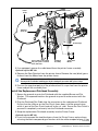
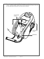
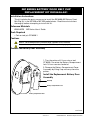
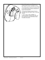
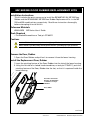
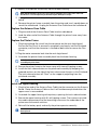
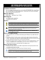
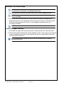
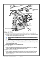
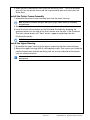
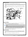
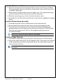
MZ Series
Mobile Printers
Maintenance Manual
for MZ 220 and MZ 320 Printers
RMAN-MZS-002 rev. A
May, 2007
Proprietary Statement
This manual contains proprietary information of Zebra Technologies Corporation and its subsidiaries (“Zebra Technologies”). It is intended solely for the information and use of parties operating and maintaining the equipment described herein. Such propriety information may not be used, reproduced, or disclosed to any other parties for any
other purpose without the expressed written permission of Zebra Technologies.
Product Improvements
Continuous improvement of products is a policy of Zebra Technologies. All specifications and designs are subject
to change without notice.
FCC Compliance Statement
Digital apparatus has been tested and found to comply with the limits for a Class B Digital Device, pursuant to Part
15 of the FCC Rules. These limits are designed to provide reasonable protection against harmful interference when
the equipment is operated in a commercial environment. This equipment generates, uses, and can radiate radio
frequency energy and, if not installed and used in accordance with the product manuals, may cause harmful interference to radio communications. Operation of this equipment in a residential area is likely to cause harmful interference in which case the user will be required to correct the interference at his own expense.
The user is cautioned that any changes or modifications not expressly approved by Zebra Technologies could void
the user’s authority to operate the equipment. This unit was tested with shielded cables on the peripheral devices.
Shielded cables must be used with the unit to insure compliance.
WARNING: EXPOSURE TO RADIO FREQUENCY RADIATION ON SOME MODELS. TO CONFORM TO FCC RF
EXPOSURE REQUIREMENTS THIS DEVICE SHALL BE USED IN ACCORDANCE WITH THE OPERATING CONDITIONS AND INSTRUCTIONS LISTED IN THIS UNIT’S USER’S MANUAL.
Canadian DOC Compliance Statement
Digital apparatus does not exceed the Class A limits for radio noise emissions from digital apparatus as set out in
the radio interference regulations of the Canadian Department of Communications.
Liability Disclaimer
Zebra Technologies takes steps to assure that its published Engineering specifications and manuals are correct;
however, errors do occur. Zebra Technologies reserves the right to correct any such errors and disclaims liability
resulting therefrom.
Limitation of Liability
In no event shall Zebra Technologies or anyone else involved in the creation, production or delivery of the accompanying product (including hardware and software) be liable for any damages whatsoever (including, without
limitation, consequential damages including loss of business profits, business interruption or loss of business information) arising out of the use of or the results of use of or inability to use such product, even if Zebra Technologies
has been advised of the possibility of such damages. Some jurisdictions do not allow the exclusion or limitation of
incidental or consequential damages, so the above limitation or exclusion may not apply to you.
Copyrights
The copyrights in this manual and the label printer described therein are owned by Zebra Technologies. All rights
are reserved. Unauthorized reproduction of this manual or the software in the label printer may result in imprisonment of up to one year and fines of up to $10,000 (17 U.S.C.506). Copyright violators may be subject to civil liability.
©2007 ZIH Corp. All trademarks and registered trademarks are property of their respective owners. All rights reserved.
RMAN-MZS-002
• -ii •
CONTENTS
SECTION 1: MZ SERIES INTRODUCTION .........................................SECT.1-4
Description ........................................................................................................Sect.1-4
Printing Technology...........................................................................................Sect.1-4
Communications ...............................................................................................Sect.1-4
User Guide ........................................................................................................Sect.1-4
Diagnostic Tools ........................................................................................ Sect.1-5
Diagnostic Label Printout ..................................................................................Sect.1-5
Label Vista™ ......................................................................................................Sect.1-5
Unit Test and Calibration Software ...................................................................Sect.1-5
Factory Technical Support ................................................................................Sect.1-6
Label Vista™ .............................................................................................. Sect.1-6
Introduction to Label Vista........................................................................ Sect.1-7
Equipment Required For Label Vista ................................................................ Sect.1-7
Starting Label Vista ........................................................................................... Sect.1-7
MZ Series Unit Test & Calibration ............................................................. Sect.1-8
Equipment Required .........................................................................................Sect.1-8
Running The Software ......................................................................................Sect.1-8
SECTION 2: REPLACEMENT PROCEDURES.................................... SECT.2-9
Tools And Supplies ...................................................................................Sect.2-9
Storage and Handling ...............................................................................Sect.2-9
MZ Series Platen And Media Cover Replacement Kits ........................ Sect.2-10
MZ Series Printhead Replacement Kits .................................................. Sect.2-12
MZ Series Upper Housing Replacement Kits ........................................ Sect.2-15
MZ Series Battery Door Belt Clip Replacement Kit RK18406-001 ........ Sect.2-17
MZ Series Door Rubber Replacement Kits ............................................ Sect.2-19
MZ Series Antenna Replacement Kit RK18408-001............................... Sect.2-20
MZ Series Main Logic Board Replacement Kit RK18409-001 ............... Sect.2-22
MZ 220 Motor and Gears Replacement Kit RK18410-001 ..................... Sect.2-25
MZ 320 Motor and Gears Replacement KIT RK18450-001 .................... Sect.2-28
MZ Series Bluetooth & 802-11 b/g Radio Replacement Kits ................. Sect.2-31
MZ Series Li-Ion Battery Accessory Kit AK18353-1...............................Sect.2-34
SECTION 3: MZ SERIES CONFIGURATOR AND REPAIR KITS ...... SECT.3-37
Using The Product Configuration Code ......................................................... Sect.3-37
Component Replacement Procedures .......................................................... Sect.3-37
MZ Series Product Configuration Code (PCC) .......................................Sect.3-38
PCC Example.................................................................................................. Sect.3-39
Factory Repair And Parts Ordering Procedure ..................................... Sect.3-40
Repair Services Contact Information ............................................................. Sect.3-40
MZ Series Accessories............................................................................Sect.3-41
MZ Series Replacement Kits...................................................................Sect.3-42
MZ Series Replacement Kits- Unit Exploded View 1 ........................... Sect.3-43
MZ Series Replacement Kits- Unit Exploded View 2 ........................... Sect.3-44
• - iii •
RMAN-MZS-002
SECTION 1: MZ SERIES INTRODUCTION
Description
The Zebra MZ Mobile Printer series are low-cost, portable, direct thermal
printers. They can be carried by the shoulder strap, sit on a work space Each
model is powered by a Li-Ion battery pack which makes it particularly useful in
environments where AC power is not readily available. The MZ series of mobile
printers deliver traditional Zebra reliability in a transportable printer for the mobile
work environment.
Printing Technology
The MZ series printers utilize direct thermal printing wherein a substrate, typically
paper, is coated with a chemical that changes to a dark color upon exposure to
heat over a period of time to form an image.
Communications
Communications between the MZ series printers and a host terminal can occur in
these basic ways:
• By a cable between the printer and its host terminal using USB protocols.
• By means of infrared light, using IrDA industry wide standards
USB and IrDA communications capabilities are standard on all MZ series printers.
• By means of an optional Bluetooth® short range radio frequency link, or.
• By means of an optional radio operating per 802.11g specifications as part of a
wireless LAN (Local Area Network).
User Guide
Use of this manual presumes a familiarity with the MZ series printers. Complete
information regarding the operation, features and specifications of the MZ series
printers can be found in the MZ Series User Guide. The MZ Series User Guide can
be found on-line at www.zebra.com.
RMAN-MZS-002 rev. A • Introduction
• -Sect.1-4 •
DIAGNOSTIC TOOLS
This section of the Printer Repair Manual describes the various diagnostic tools
available from Zebra and instructions on contacting technical support services
offered by Zebra.
Following sections contains explanations on the product’s configuration structure,
troubleshooting guide for isolating common printer problems, illustrated parts
breakdowns for specific models and specialized component replacement
procedures.
Diagnostic Label Printout
The printer can create a configuration label which exercises all of the printhead’s
thermal elements and create a detailed report of the printer’s settings and any
special files that may be loaded into memory.
This Diagnostic label can be used as an initial tool to diagnose such basic printer
problems as missing printhead elements, missing or incorrect application files or
incorrect settings.
Instructions on printing a diagnostic label can be found in the MZ Series User
Guide, available on-line at www.zebra.com
Label Vista™
Label Vista is a Windows™ based label design program, which also offers
comprehensive diagnostic and utility routines. The ability to create, edit and print
files and perform diagnostic tasks makes Label Vista an extremely powerful tool
for maintaining the Zebra line of portable printers.
Label Vista may be downloaded from: www.zebra.com.
Unit Test and Calibration Software
Zebra authorized service organizations have access to powerful test and
calibration software which allows them to perform more advanced procedures.
These procedures are identified by the following message:
The following procedure can only be performed by Zebra authorized service organizations using
approved equipment and software.
If you do not have this approval, do not attempt to perform these procedures.
If they are performed improperly or incompletely, the printer will not function
properly.
• - Sect.1-5 •
Introduction •RMAN-MZS-002 rev. A
Factory Technical Support
Factory technical support and other contact information is available per the
following:
In the Americas contact
Regional Headquarters
Technical Support
Customer Service Dept.
Zebra Technologies International, LLC
333 Corporate Woods Parkway
Vernon Hills, Illinois 60061.3109 U.S.A.
T: +1 847 793 2600
Toll-free +1 800 423 0422
T: +1 847 913 2259
F: +1 847 913 2578
E: Hardware:
[email protected]
E: Software:
[email protected]
For printers, parts, media,
and ribbon, please call your
distributor, or contact us.
T: +1 866 230 9494
F: +1 847 913 8766
E: [email protected]
In Europe, Africa, the Middle East, and India contact
Regional Headquarters
Technical Support
Internal Sales Dept.
Zebra Technologies Europe Limited
Zebra House
The Valley Centre, Gordon Road
High Wycombe
Buckinghamshire HP13 6EQ, UK
T: +44 (0)1494 472872
F: +44 (0) 1494 450103
Self Service Knowledgebase:
For printers, parts, media,
and ribbon, please call your
distributor, or contact us.
T: +44 (0) 1494 768316
F: +44 (0) 1494 768244
E: [email protected]
www.zebra.com/knowledgebase
Email Back Technical Library:
Send email to: [email protected]
Subject: Emaillist
On-Line case registration: www.zebra.com/techrequest
In the Asia Pacific region contact
Regional Headquarters
Technical Support
Customer Service
Zebra Technologies Asia Pacific, LLC
Refer to “About Zebra/Contact Us” at
www.zebra.com for complete contact information.
T: +65 6858 0722
F: +65 6885 0838
T: +65 6858 0722
F: +65 6885 0838
E: tsasiapacifi[email protected]
For printers, parts, media,
and ribbon, please call
your distributor, or
contact us.
T: +65 6858 0722
F: +65 6885 0837
LABEL VISTA™
RMAN-MZS-002 rev. A • Introduction
• -Sect.1-6 •
INTRODUCTION TO LABEL VISTA
Label Vista is a program running under the Windows™ environment that allows
users to design labels which can be printed on the full range of Zebra mobile
printers.
Label Vista also provides a powerful set of diagnostics tools which use familiar
Windows “point and click” routines. These tools can be reached under the Printer
selection on the Label Vista menu bar. It is recommended that the Label Vista
documentation package be consulted for a more detailed description of the printer
diagnostics available in Label Vista.
Equipment Required For Label Vista
1. An IBM-PC Compatible with:
• Pentium CPU
• 256 MB RAM
• 1.44 MB Floppy Drive
• 1 GB Hard Drive
• CD-ROM drive
• SVGA 14” monitor and SVGA card
• 2 Serial Ports, 1 Parallel Port
• A USB port
• Windows 95/98 or NT
2. USB Interface Cable part number AT17010-1 or a Zebra approved equivalent.
3. Digital Multimeter (Fluke 77 or similar) with a minimum impedance >100 KΩ
4. Spare batteries, charger and test media specific to the printer. Refer to the table
in the “Tools and Supplies” topic in Section 2 of this manual.
Starting Label Vista
1. Plug the USB cable into a USB port on your PC
2. Plug the other end of the interface cable into the printer’s USB port.
3. Start the Label Vista program by either clicking on the Label Vista shortcut on
your desk top, or using the “Start” button.
4. Use Label Vista’s extensive built-in Help topics for instructions on using its many
design, editing and diagnostic features.
• - Sect.1-7 •
Introduction •RMAN-MZS-002 rev. A
MZ SERIES UNIT TEST & CALIBRATION
Equipment Required
1. A computer with the following minimum configuration:
• Pentium CPU
• 256 MB RAM
• 1.44 MB Floppy Drive
• 1 GB Hard Drive
• CD-ROM drive
• SVGA 14 in. monitor and SVGA card
• 2 Serial Ports
• USB Port
• Windows 95/9, NT or 2000
• Unit Test Software version 3.3 or higher installed with the “euro”
configuration.
2. A bar code scanner, using either RS232 (serial) keyboard “wedge” or USB
communications. (Example: Symbol Model LS1908 series)
3. USB Interface Cable part number AT17010-1 or a Zebra approved equivalent.
4. Spare batteries, chargers and test media specific to the printer. Refer to the table
in the “Tools and Supplies” topic in Section 2 of this manual.
Running The Software
CAUTION: DO NOT disconnect the communications cable at any time during the Unit Test
procedure unless prompted to do so by the software!
IMPORTANT: Certain replacement procedures in this manual will require running the test
procedure to verify a repair. It is recommended that you perform the entire unit test sequence for
these procedures to ensure all printer functions are functional after the replacement.
To Start
• Launch the Unit Test Application.
• Plug the Serial Interface Cable into the printer’s communication port.
• Follow the on-screen instructions.
RMAN-MZS-002 rev. A • Introduction
• -Sect.1-8 •
SECTION 2: REPLACEMENT PROCEDURES
TOOLS AND SUPPLIES
Make use of the following tools and supplies for maintaining the printer and
installing the repair kits:
Hand Tools
• #0 or #1 Phillips Head Screw Driver
• A 1/8” Hex Driver or equivalent diameter dowel pin, at least 2” long
Supplies
• Cleaning Pen (10 pack), p/n AN11209-1
• Cleaning Kit with Cleaning Pen, and Cotton Swabs p/n AT702-1
• Isopropyl alcohol
• Media, Batteries, and Chargers for MZ series printers per table below:
Mobile Printer
Model #
3.2 mil Journal
Media (for Life
Test)
MZ 220
LD-D2KV5E
MZ 320
LD-D3KV5B
Battery
Replacement Kit
AK18353-1
Single Charger/
Quad Power
Station1
AK18355-x/
AK18342-x
1. Full part number is determined by intended country of use. Contact your re-seller of the factory for complete
information.
STORAGE AND HANDLING
Handling:
The use of an ESD wrist strap at a properly grounded workstation is required
when handling printed circuit boards or other sensitive electronic components.
The ESD strap prevents any electrostatic damage to occur while assembling
these components. The use of the ESD strap will be noted in the applicable
instructions.
This symbol indicates that the operator must wear a properly grounded ESD strap to perform the
repair procedure.
Storage
Replacement kits which are sensitive to ESD damage are supplied in static
resistant packaging. Always keep these parts in their original packaging until they
are to be installed.
• Sect.2-9 •
RMAN-MZS-002 • MZ Series Repair Procedures
MZ SERIES PLATEN AND MEDIA COVER
REPLACEMENT KITS
Installation Instructions
This kit includes the parts necessary to install the RK18403-001 and the
RK18446-001 Platen and Media Cover Kit in the models MZ 220 and MZ 320
printers respectively. Read these instructions thoroughly before attempting to
install these kits.
Reference Materials
UMAN-MZS
MZ Series Users’ Guide
Tools Required
• #1 Phillips head screwdriver
• A 1/8” Hex Driver or equivalent diameter dowel pin, at least 2” long
Cautions
Caution • This installation must be performed only by a qualified service technician.
Always turn the printer off before performing any repair procedures, unless otherwise specified.
Removing the Media
Cover
1. Press the latch release
button and open the Media
Cover Assembly as though
loading media. Remove any
media from the printer.
2. Remove and retain the
two screws inside the media
compartment securing the
upper housing.
NOTE: You may elect to slightly loosen the two screws near the top of the printer that secure the
upper housing.
3. Lift one side of the upper housing to expose the pivot shaft securing the Media
Cover Assembly to the lower housing.
4. Use the 1/8” hex driver to press the pivot pin out of the lower housing. You will
have to lift the other side of the upper housing to allow the pivot pin to side out
completely.
5. Remove and retain the media cover spring when the pivot pin is removed.
6. Remove the Media Cover Assembly from the printer.
RMAN-MZS-002 • MZ Series Repair Procedures
• Sect.2-10 •
Install the Replacement Cover
1.
Align the replacement Media Cover
Assembly with the lower housing and
slide the pivot pin through the Media
Cover Assembly and into the lower
housing.
Media Cover
Spring
2. Drop the straight end of the media cover spring into the lower housing and
align the open coils of the spring on the lower housing to allow the pivot pin to
pass through it. Press the pivot pin completely into the lower housing.
3. Snap the upper housing back into position and re-secure all the attaching
screws.
• Sect.2-11 •
RMAN-MZS-002 • MZ Series Repair Procedures
MZ SERIES PRINTHEAD REPLACEMENT KITS
Installation Instructions
This kit includes the parts necessary to install the RK18404-001 Printhead
Replacement Kit in the model MZ 220 printer and the RK18447-001 Printhead
Replacement Kit in the MZ 320 Printer. The procedures for both kits are similar
except for the differences noted below. Read these instructions thoroughly before
attempting to install this kit.
Reference Materials
UMAN-MZS
MZ Series Users’ Guide
Tools Required
• #1 Phillips head screwdriver
Cautions
Always turn the printer off before performing any repair procedures, unless otherwise specified.
You must use an ESD strap and work at a properly grounded workstation (antistatic mat or tray).
All electronic components must be placed on an ESD protective tray. If stored, any electronic
components must be placed in antistatic bags
The following procedure can only be performed by Zebra authorized service organizations using
approved equipment and software.
Remove the Upper Housing
1 Turn the printer off, and remove the battery pack. Remove any media from the
printer.
2. Remove and retain the four screws retaining the upper housing to the printer
frame. Two screws are inside the media compartment and the remaining two are
on the underside of the printer near the control switches.
3. Remove the upper housing. Retain the latch release button.
NOTE: If the printer is equipped with a radio option: carefully unplug the antenna cable from the
Antenna PCB mounted in the upper housing. Refer to the procedure for RK18408-001, MZ Series
Antenna replacement kit, for more details.
Remove the Printer Frame
1. Remove the two screws securing the printer frame to the lower housing.
2. Lift the Printer frame slightly to gain access to the motor connector and un-plug
it.
3. Un-latch the printhead connector.
4. Carefully lift the printer frame away from the lower housing.
MZ 220 NOTE: The two drive gears that mesh with the motor on the printer frame will become
loose. You can temporarily secure them in place with a piece of tape.
Remove the Printhead Assembly
1. Un-plug the Printhead flex circuit from the main logic board.
2. Remove the two Springs from the printer frame and the Printhead..
RMAN-MZS-002 • MZ Series Repair Procedures
• Sect.2-12 •
Printer
Frame
Printhead Flex Circuit
Printhead
Spring (2)
Ground Strap)
Snap Printhead Assembly
into pivot points on Printer
frame, both sides.
Printhead
Assembly
Screw & Flat
Washer
3. If so equipped, remove the radio board from the printer frame assembly.
Optional step for MZ 320:
4. Remove the Gear Retainer from the printer frame. Remove the two (black) gears
farthest from the Motor from the printer frame.
NOTE: Refer to procedure RK18450-001 MZ 320 Motor and Gears for more complete details.
You may wish to retain the remaining gear in place during this procedure with a piece of tape.
5 Push on the two pivot points of the printhead until it snaps free from the printer
frame and pull the assembly free.
Install the Replacement Printhead Assembly
1. Secure the ground strap to the Printhead with the supplied Screw and Flat
Washer. The exposed metal on the ground strap must make contact with the
Printhead.
2. Plug the Printhead Flex Cable into the connector on the replacement Printhead.
Ensure that the stiffener on the Flex Circuit faces down, and the ground strap,
which is part of the Flex Circuit leads off to the r.h. side. Ensure the Flex Circuit is
pressed in completely and evenly into the Printhead connector.
3. Snap the replacement Printhead assembly into the Printer Frame.
Optional step for MZ 320:
4. If you have removed the two black gears from the Printer Frame, replace them,
ensuring the black compound gear meshes with the white compound gear. If you
continued
• Sect.2-13 •
RMAN-MZS-002 • MZ Series Repair Procedures
have secured the remaining drive gear with a piece of tape during the printhead
installation, remove it at this time.
Reassemble the Gear Retainer to the Printer Frame
NOTE: Refer to procedure RK18450-001 MZ 320 Motor and Gears for more complete details.
5. Attach the two replacement Springs to each side of the Printhead Assembly and
the printer frame.
6. If so equipped, re-install the radio board into the printer frame.
7. Plug the Flex Circuit into the connector on the main logic board. Ensure the Flex
Circuit is pressed in completely and evenly into the Printhead connector, and that
the connector is latched on both sides to secure the Flex Circuit.
Install the Printer Frame Assembly
1. Partially re-assemble the printer frame assembly back into the lower housing,
leaving enough room to access the motor connector.
MZ 220 NOTE: If you have secured the drive gears with a piece of tape during the printhead
installation, remove it before re-assembling the printer frame.
2 Plug the motor connector into the Main Logic board.
3. Lower the printer frame into the printer, ensuring that the leads from the motor
do not become pinched between the printer frame and the Main Logic Board.
Secure the printer frame to the lower cover with two self-tapping screws.
4. Install the latch release button on the Printhead Assembly by dropping the
grooved sections on the side of the latch release over the pins in the Printhead.
The latch release button will “float” on the supports projecting from the
Printhead Assembly.
NOTE: The “flat “ side of the latch release button faces the Printhead.
Install the Upper Housing
1. Assemble the upper housing to the printer, capturing the latch release button.
NOTE: If the printer is equipped with a radio option: carefully plug the antenna cable back
into the antenna PCB at this time. Refer to the procedure for RK18408-001, MZ Series Antenna
replacement kit, for more details.
2. Secure the upper housing with (4) self-tapping screws. Two screws are inside the
media compartment and the remaining two are on the underside of the printer
near the control switches.
It is recommended that the complete unit test procedure be performed whenever a printhead
assembly has been replaced.
RMAN-MZS-002 • MZ Series Repair Procedures
• Sect.2-14 •
MZ SERIES UPPER HOUSING REPLACEMENT KITS
Installation Instructions
This kit includes the parts necessary to install the RK18405-001 and RK18448-001
Upper Housing Kits in the model MZ 220 and MZ 320 printers respectively. Read
these instructions thoroughly before attempting to install either of these kits.
Reference Materials
UMAN-MZS
MZ Series Users’ Guide
Tools Required
• #1 Phillips head screwdriver
Cautions
Caution • This installation must be performed only by a qualified service technician.
Always turn the printer off before performing any repair procedures, unless otherwise specified.
You must use an ESD strap and work at a properly grounded workstation (antistatic mat or tray).
All electronic components must be placed on an ESD protective tray. If stored, any electronic
components must be placed in antistatic bags
Remove the Upper Housing
1. Turn the printer off, and remove the battery pack. Remove any media from the
printer.
2. Remove and retain the four screws retaining the upper housing to the printer
frame. Two screws are inside the media compartment and the remaining two are
on the underside of the printer near the control switches.
3. Remove the upper housing. Retain the latch release button.
NOTE: If the printer is equipped with a radio option: carefully remove the antenna from the upper
housing. Refer to the procedure for RK18408-001, MZ Series Antenna replacement kit, for more
details.
To remove the antenna without damage it may be necessary to break away the retaining tabs on
the upper housing you are replacing.
Install the Replacement Upper Housing
1. If the printer is equipped with a radio, install the antenna into the replacement
Upper Housing. Refer to the procedure for RK18408-001, MZ Series Antenna
replacement kit, for more details.
2. Ensure the latch release button is re-installed on the printhead assembly by
dropping the grooved sections on the side of the latch release over the pins in
the printhead. The latch release button will “float” on the supports projecting
from the Printhead Assembly.
NOTE: The “flat “ side of the latch release button faces the Printhead.
3. Assemble the upper housing to the printer, capturing the latch release button.
continued
• Sect.2-15 •
RMAN-MZS-002 • MZ Series Repair Procedures
4. Secure the upper housing with (4) self-tapping screws. Use the two shorter
screws inside the media compartment and the remaining two longer screws are
on the underside of the printer near the control switches.
Short Self-Tapping
Screw (2)
Long Self-Tapping
Screw (2)
Upper Housing
RMAN-MZS-002 • MZ Series Repair Procedures
• Sect.2-16 •
MZ SERIES BATTERY DOOR BELT CLIP
REPLACEMENT KIT RK18406-001
Installation Instructions
This kit includes the parts necessary to install the RK18406-001 Battery Door/
Belt Clip Kit in the MZ 220 or MZ 320 model printer. Read these instructions
thoroughly before attempting to install this kit.
Reference Materials
UMAN-MZS
MZ Series Users’ Guide
Tools Required
• Coin or tool p/n CF18330-1
Cautions
Caution • This installation must be performed only by a qualified service technician.
Unless otherwise specified, always turn the printer off before performing any repair procedures.
Remove the Battery Door Assembly
1. Turn the printer off. Use a coin or tool
CF18330-1 to rotate the Battery Compartment
lock 1/4 turn counter clockwise.
2. Remove the Battery Compartment Cover
Assembly by lifting it up and away from the
printer.
Install the Replacement Battery Door
Assembly
Belt Clip
Battery Compartment Cover
Battery Compartment Lock
continued
• Sect.2-17 •
RMAN-MZS-002 • MZ Series Repair Procedures
1. Install the replacement Battery
Compartment Cover Assembly. Ensure
the slot on the Latch is parallel to the long
axis of the printer and insert the three tabs
on the Door into the printer and lower the
cover onto the printer.
2. Ensure the battery leads will not be
pinched when the Battery Door is secured
in place.
3. Use a coin or tool CF18330-1 to
rotate the Battery Compartment lock 1/4
turn clockwise to lock the Battery Door
Assembly into place.
RMAN-MZS-002 • MZ Series Repair Procedures
• Sect.2-18 •
MZ SERIES DOOR RUBBER REPLACEMENT KITS
Installation Instructions
This kit includes the parts necessary to install the RK18407-001 Kit MZ 220 Door
Rubber and the RK18449-001 MZ 320 Door Rubber Replacement Kits in the MZ
220 and 320 model printers respectively. Read these instructions thoroughly
before attempting to install this kit.
Reference Materials
UMAN-MZS
MZ Series Users’ Guide
Tools Required
• Flat bladed Screwdriver or Tool p/n CF18427-1
Cautions
Caution • This installation must be performed only by a qualified service technician.
Unless otherwise specified, always turn the printer off before performing any repair procedures.
Remove the Door, Rubber
1. Open the Door Rubber and pull on it to remove it from the lower housing.
Install the Replacement Door, Rubber
1. Insert the retaining feature of the Door, Rubber into the slot of the lower housing.
2. Using the flat side of a slotted head screwdriver, or tool p/n CF18427-1, push the
retaining feature of the Door, Rubber into the slot, so that it is captured inside the
lower housing.
Insert into slot in Lower
Housing. Use flat bladed
screwdriver or tool p/n
CF18427-1.
Door, Rubber
continued
• Sect.2-19 •
RMAN-MZS-002 • MZ Series Repair Procedures
MZ SERIES ANTENNA
REPLACEMENT KIT RK18408-001
Installation Instructions
This kit includes the parts necessary to install the RK18408-001 RF Antenna Kit in
the MZ 220 or MZ 320 model printer. Read these instructions thoroughly before
attempting to install this kit.
Reference Materials
UMAN-MZS
MZ Series Users’ Guide
Tools Required
• #1 Phillips head screwdriver
• Slotted head screwdriver.
Cautions
Caution • This installation must be performed only by a qualified service technician.
Unless otherwise specified, always turn the printer off before performing any repair procedures.
The following procedure can only be performed by Zebra authorized service organizations using
approved equipment and software.
Remove the Upper Housing
1. Turn the printer off, and remove the battery pack. Remove any media from the
printer.
2. Remove and retain the four screws retaining the upper housing to the printer
frame. Two screws are inside the media compartment and the remaining two are
on the underside of the printer near the control switches.
3. Remove the upper housing. Remove and retain the Latch Release Button.
Remove the Antenna
1. Turn the Upper cover upside down. Carefully unplug the Antenna Coax Cable
from the Antenna.
2. Use the slotted head screwdriver to
Antenna
lift the exposed edge of the antenna
Coax Cable
over the lip surrounding the opening
for the latch release button. Slide
Antenna
the Antenna out from under the
retainers on the upper cover.
Remove the Printer Frame
NOTE: perform the next four steps
only if you are also replacing the antenna coax
cable included with this repair kit.
1.
Remove the two screws
securing the printer frame to the
lower housing.
RMAN-MZS-002 • MZ Series Repair Procedures
• Sect.2-20 •
2. Carefully lift the printer frame away from the lower housing.
NOTE FOR MZ 220 ONLY: The two drive gears that mesh with the motor on the printer frame will
become loose. You can temporarily secure them in place with a piece of tape.
3. Unplug the motor connector and the printhead flex circuit from the main logic
board.
4. Remove the printer frame assembly from the printer and turn it upside down to
reveal the radio board. Unplug the Antenna Coax Cable from the radio board.
Replace the Antenna Coax Cable
1. Plug one end of the Antenna Coax Cable into the radio board.
2. Lead the other end of the Antenna Cable through the printer frame away from
the motor.
Replace the Printer Frame
1. Plug the printhead flex circuit into the connector on the main logic board.
Ensure the Flex Circuit is pressed in completely and evenly into the Printhead
connector, and that the connector is latched on both sides to secure the Flex
Circuit.
2. Plug the motor connector back into the main logic board.
3. Assemble the printer frame assembly back into the lower housing.
NOTE FOR MZ 220 ONLY: Remove the tape you have used to secure the drive gears before reassembling the printer frame.
4. Secure the printer frame to the lower cover with two self-tapping screws.
5. Install the latch release button on the printhead assembly by dropping the
grooved sections on the side of the latch release over the pins in the Printhead.
The latch release button will “float” on the supports projecting from the
printhead assembly.
NOTE: The “flat “ side of the latch release button faces the printhead.
Install the Upper Housing
1. Plug the free end of the Antenna Coax Cable into the connector on the Antenna
Board. Route the Antenna Cable so that it will not become pinched when the
upper cover is reassembled.
2. Assemble the upper housing to the printer, capturing the latch release button.
3. Secure the upper housing with (4) self-tapping screws. Two screws are inside
the media compartment and the remaining two are on the underside of the
printer near the control switches.
4. Reinstall the battery pack, and verify the printer operates correctly.
It is recommended that the complete unit test procedure be performed whenever an antenna has
been replaced.
• Sect.2-21 •
RMAN-MZS-002 • MZ Series Repair Procedures
MZ SERIES MAIN LOGIC BOARD
REPLACEMENT KIT RK18409-001
Installation Instructions
This kit includes the parts necessary to install the RK18409-001 Main Logic Board
Kit in the MZ 220 or MZ 320 model printer. Read these instructions thoroughly
before attempting to install this kit.
Reference Materials
UMAN-MZS
MZ Series Users’ Guide
Tools Required
• #1 Phillips head screwdriver
• Slotted head screwdriver.
Cautions
Caution • This installation must be performed only by a qualified service technician.
Unless otherwise specified, always turn the printer off before performing any repair procedures.
You must use an ESD strap and work at a properly grounded workstation (antistatic mat or tray).
All electronic components must be placed on an ESD protective tray. If stored, any electronic
components must be placed in antistatic bags
The following procedure can only be performed by Zebra authorized service organizations using
approved equipment and software.
Remove the Upper Housing
1. Turn the printer off, and remove the battery pack. Remove any media from the
printer.
2. Remove and retain the four screws retaining the upper housing to the printer
frame. Two screws are inside the media compartment and the remaining two are
on the underside of the printer near the control switches.
3. Remove the upper housing. Remove and retain the latch release button. If the
printer is equipped with a radio option, you may wish to unplug the antenna
cable from the antenna card mounted in the upper cover.
Remove the Printer Frame
1. Remove the two screws in the media compartment securing the printer frame
assembly to the lower housing.
2. Carefully lift the printer frame away from the lower housing.
NOTE FOR MZ 220 ONLY: The two drive gears that mesh with the motor on the printer frame will
become loose. You can temporarily secure them in place with a piece of tape.
3. Unplug the motor connector and the flex circuit from the printhead to the Main
RMAN-MZS-002 • MZ Series Repair Procedures
• Sect.2-22 •
logic board.
4. Remove the printer frame assembly from the printer.
Remove the Main Logic Board Assembly
1. Remove and retain the (1) screw securing the Main Logic Board to the Lower
Housing.
2. Remove the Main Logic Board.
Install The Replacement Main Logic Board
1. Place the replacement Main Logic Board in the Lower Housing.
2. Secure the Main Logic Board to the Lower Housing with the (1) retained screw.
3. Plug the printhead flex circuit into the connector on the main logic board. Ensure
the flex circuit is pressed in completely and evenly into the printhead connector,
and that the connector is latched on both sides to secure the flex circuit.
4. Plug the motor connector back into the main logic board.
Motor
Connector
Printer Frame
Assembly
Printhead
Connector
Main Logic
Board
continued
• Sect.2-23 •
RMAN-MZS-002 • MZ Series Repair Procedures
Assemble The Printer Frame
NOTE FOR MZ 220 ONLY: If you have secured the drive gears with a piece of tape when removing
the printer frame, remove it before re-assembling the printer frame.
1. Secure the printer frame to the lower cover with two self-tapping screws.
NOTE: Ensure the antenna cable is routed so that it will not become pinched when the upper
cover is reassembled.
2. Install the latch release button on the printhead assembly by dropping the
grooved sections on the side of the latch release over the pins in the Printhead.
The latch release button will “float” on the supports projecting from the
printhead assembly.
NOTE: The “flat “ side of the latch release button faces the Printhead.
Install the Upper Housing
1. Assemble the upper housing to the printer, capturing the latch release button.
2. Secure the upper housing with (4) self-tapping screws. Two screws are inside the
media compartment and the remaining two are on the underside of the printer
near the control switches.
It is recommended that the complete unit test procedure be performed whenever a main logic
board has been replaced.
RMAN-MZS-002 • MZ Series Repair Procedures
• Sect.2-24 •
MZ 220 MOTOR AND GEARS
REPLACEMENT KIT RK18410-001
Installation Instructions
This kit includes the parts necessary to install the RK18410-001 Motor and Gear
Kit in the MZ 220 model printer. Read these instructions thoroughly before
attempting to install this kit.
Reference Materials
UMAN-MZS
MZ Series Users’ Guide
Tools Required
• #1 Phillips head screwdriver
Cautions
The following procedure can only be performed by Zebra authorized service organizations using
approved equipment and software.
Unless otherwise specified, always turn the printer off before performing any repair procedures.
You must use an ESD strap and work at a properly grounded workstation (antistatic mat or tray).
All electronic components must be placed on an ESD protective tray. If stored, any electronic
components must be placed in antistatic bags
Remove the Upper Housing
1. Turn the printer off, and remove the battery pack. Remove any media from the
printer.
2. Remove and retain the four screws retaining the upper housing to the printer
frame. Two screws are inside the media compartment and the remaining two are
on the underside of the printer near the control switches.
3. Remove the upper housing. Retain the latch release button.
Remove the Printer Frame
1. Remove the two screws securing the printer frame to the lower housing.
2. Carefully lift the printer frame away from the lower housing.
NOTES: The two drive gears that mesh with the motor on the printer frame will become loose. If
you are not replacing them with the gears supplied with this kit, you can temporarily secure them
in place with a piece of tape.
Do not put excessive strain on the flex circuit from the Printhead or the connector leading from
the motor to the main logic board.
Remove the Motor
1. Remove the screw securing the Motor to the printer frame.
2. Rotate the motor clockwise (when facing the outside of the printer frame) until
the mounting ear of the motor is free of its retaining feature on the printer frame.
3. Flex the section of the printer frame that is retaining the motor slightly downward
and twist the motor free of the printer frame. Unplug the motor from the main
logic board.
continued
• Sect.2-25 •
RMAN-MZS-002 • MZ Series Repair Procedures
Rotate in this
direction to install
motor
Black Gear
Motor
White Gear
Motor Connector
Replace the Motor
1. Plug the connector from the replacement Motor into the main logic board.
2. Flex the printer frame slightly to allow the gear pinion on the replacement Motor
to slide into its opening on the printer frame.
NOTE: Ensure the wires of the Motor emerge from the l.h. side as you face the pinion gear end of
the motor.
3. Rotate the Motor counter-clockwise when facing the outside of the printer frame
until the mounting ear of the Motor engages with its retaining feature on the
printer frame, and the mounting hole on the other mounting ear lines up with the
insert on the printer frame.
4. Secure the Motor with the supplied screw.
Remove the Gears
1. If you are replacing the drive Gears with the ones supplied with this repair kit,
remove the old gears by sliding them off their shafts.
Install the Replacement Gears
1. Slide the white replacement Gear onto the shaft nearest the Motor. The large
diameter gear must be closest to the printer frame and will mesh with the
Motor’s pinion gear.
RMAN-MZS-002 • MZ Series Repair Procedures
• Sect.2-26 •
2. Slide the black replacement Gear onto the remaining shaft. The small diameter
gear will face the printer frame and the large diameter gear will mesh with the
white Gear.
Install the Printer Frame Assembly
1. Assemble the printer frame assembly back into the lower housing.
NOTE: If you have secured the drive gears with a piece of tape, remove it before re-assembling
the printer frame.
2 Secure the printer frame to the lower cover with two self-tapping screws.
3. Install the latch release button on the Printhead Assembly by dropping the
grooved sections on the side of the latch release over the pins in the Printhead.
The latch release button will “float” on the supports projecting from the
Printhead Assembly.
NOTE: The “flat “ side of the latch release button faces the Printhead.
Install the Upper Housing
1. Assemble the upper housing to the printer, capturing the latch release button.
2. Secure the upper housing with (4) self-tapping screws. Two screws are inside the
media compartment and the remaining two are on the underside of the printer
near the control switches.
It is recommended that the complete unit test procedure be performed whenever a motor has
been replaced.
• Sect.2-27 •
RMAN-MZS-002 • MZ Series Repair Procedures
MZ 320 MOTOR AND GEARS REPLACEMENT KIT
RK18450-001
Installation Instructions
This kit includes the parts necessary to install the RK18450-001 Motor and Gear
Kit in the MZ 320 model printer. Read these instructions thoroughly before
attempting to install this kit.
Reference Materials
UMAN-MZS
MZ Series Users’ Guide
Tools Required
• #1 Phillips head screwdriver
Cautions
Caution • This installation must be performed only by a qualified service technician.
Unless otherwise specified, always turn the printer off before performing any repair procedures.
You must use an ESD strap and work at a properly grounded workstation (antistatic mat or tray).
All electronic components must be placed on an ESD protective tray. If stored, any electronic
components must be placed in antistatic bags
Remove the Upper Housing
1. Turn the printer off, and remove the battery pack. Remove any media from the
printer.
2. Remove and retain the four screws retaining the upper housing to the printer
frame. Two screws are inside the media compartment and the remaining two are
on the underside of the printer near the control switches.
3. Remove the upper housing. Retain the latch release button.
Remove the Printer Frame
1. Remove the two screws securing the printer frame to the lower housing.
2. Carefully lift the printer frame away from the lower housing.
Do not put excessive strain on the flex circuit from the Printhead or the connector leading from
the motor to the main logic board.
RMAN-MZS-002 • MZ Series Repair Procedures
• Sect.2-28 •
Remove the Motor
1. Remove the screw securing the Motor to the printer frame.
2. Rotate the motor counterclockwise (when facing the outside of the printer frame)
until the mounting ear of the motor is free of its retaining feature on the printer
frame.
3. Pull the motor free of the printer frame. Unplug the motor from the main logic
board.
Rotate in this
direction to install
motor
Black Compound
Gear
Motor
Black Gear
Motor Connector
White Compound
Gear
Gear Cover
Replace the Motor
1. Plug the connector from the replacement Motor into the main logic board.
2. Assemble the replacement Motor to the printer frame.
NOTE: Ensure the wires of the Motor emerge from the l.h. side as you face the pinion gear end of
the motor.
3. Rotate the Motor clockwise as shown until the mounting ear of the Motor
engages with its retaining feature on the printer frame, and the mounting hole on
the other mounting ear lines up with the insert on the printer frame.
4. Secure the Motor with the supplied screw.
Remove the Gears
1. If you are replacing the drive Gears with the ones supplied with this repair kit,
remove the Gear Cover by removing the securing screw and pulling the cover
off.
2. Remove the (3) old gears by sliding them off their shafts.
continued
• Sect.2-29 •
RMAN-MZS-002 • MZ Series Repair Procedures
Install the Replacement Gears
1. Slide the white replacement Compound Gear onto the shaft nearest the Motor.
The large diameter gear must be closest to the printer frame and will mesh with
the Motor’s pinion gear.
2. Slide the black Compound Gear onto the middle shaft. The large diameter gear
will face the printer frame and will mesh with the white Gear.
3. Slide the remaining gear on the last shaft on the printer frame.
4. Assemble the new Gear Cover to the Printer Frame with the supplied self-tapping
Screw.
Install the Printer Frame Assembly
1. Assemble the printer frame assembly back into the lower housing.
2 Secure the printer frame to the lower cover with two self-tapping screws.
3. Install the latch release button on the Printhead Assembly by dropping the
grooved sections on the side of the latch release over the pins in the Printhead.
The latch release button will “float” on the supports projecting from the
Printhead Assembly.
NOTE: The “flat “ side of the latch release button faces the Printhead.
Install the Upper Housing
1. Assemble the upper housing to the printer, capturing the latch release button.
2. Secure the upper housing with (4) self-tapping screws. Two screws are inside the
media compartment and the remaining two are on the underside of the printer
near the control switches.
It is recommended that the complete unit test procedure be performed whenever a motor has
been replaced.
RMAN-MZS-002 • MZ Series Repair Procedures
• Sect.2-30 •
MZ SERIES BLUETOOTH & 802-11 B/G RADIO
REPLACEMENT KITS
Installation Instructions
This kit includes the parts necessary to install the RK18411-001 MZ Series
Bluetooth Radio and RK18412-001 MZ Series 802.11b/g Radio in the MZ 220 or MZ
320 model printer. Read these instructions thoroughly before attempting to install
this kit.
Reference Materials
UMAN-MZS
MZ Series Users’ Guide
Tools Required
• #1 Phillips head screwdriver
• Slotted head screwdriver
Cautions
Caution • This installation must be performed only by a qualified service technician.
Unless otherwise specified, always turn the printer off before performing any repair procedures.
You must use an ESD strap and work at a properly grounded workstation (antistatic mat or tray).
All electronic components must be placed on an ESD protective tray. If stored, any electronic
components must be placed in antistatic bags
The following procedure can only be performed by Zebra authorized service organizations using
approved equipment and software.
Remove the Upper Housing
1. Turn the printer off, and remove the battery pack. Remove any media from the
printer.
2. Remove and retain the four screws retaining the upper housing to the printer
frame. Two screws are inside the media compartment and the remaining two are
on the underside of the printer near the control switches.
3 Remove the upper housing. Remove and retain the latch release button.
NOTE: You may elect to disconnect the antenna coax cable from the Antenna for ease of handling.
Remove the Printer Frame
1. Remove the two screws securing the printer frame to the lower housing.
2. Carefully lift the printer frame away from the lower housing.
NOTE FOR MZ 220 ONLY: The two drive gears that mesh with the motor on the printer frame will
become loose. You can temporarily secure them in place with a piece of tape.
3. Unplug the motor connector and the flex circuit from the printhead to the Main
logic board.
continued
• Sect.2-31 •
RMAN-MZS-002 • MZ Series Repair Procedures
Printer Frame Assembly
Antenna Coax Cable
Bluetooth Radio
Board
or
802.11b/g Radio Board
Plug Antenna Coax
Cable into connector
on Radio Board
Slide Radio Board
in this direction to
install.
4. Remove the printer frame assembly from the printer and turn it upside down to
reveal the radio board. Unplug the Antenna Coax Cable from the radio board.
Remove the Radio Board
1. Slide the Radio board out of the printer frame. You can use a slotted screwdriver
to act as a lever between the printer frame and the edge of the Radio Board.
Install The Replacement Radio Board
1. Slide the replacement radio board into the printer frame. Note that the connector
for the antenna coax cable must face “up”.
2. Plug the antenna coax cable from the upper housing into the Radio Board.
Replace the Printer Frame
1. Plug the printhead flex circuit into the connector on the main logic board. Ensure
the flex circuit is pressed in completely and evenly into the printhead connector,
and that the connector is latched on both sides to secure the flex circuit.
2. Plug the motor connector back into the main logic board.
3. Assemble the printer frame assembly back into the lower housing.
RMAN-MZS-002 • MZ Series Repair Procedures
• Sect.2-32 •
NOTE FOR MZ 220 ONLY: If you have secured the drive gears with a piece of tape when removing
the printer frame, remove it before re-assembling the printer frame.
4 Secure the printer frame to the lower cover with two self-tapping screws.
NOTE: Ensure the antenna cable is routed so that it will not become pinched when the upper
cover is reassembled.
5. Install the latch release button on the printhead assembly by dropping the
grooved sections on the side of the latch release over the pins in the Printhead.
The latch release button will “float” on the supports projecting from the
printhead assembly.
NOTE: The “flat “ side of the latch release button faces the Printhead.
Install the Upper Housing
1. Assemble the upper housing to the printer, capturing the latch release button.
NOTE: If you have disconnected the antenna coax cable from the antenna, reconnect it at this
time.
2.
Secure the upper housing with (4) self-tapping screws. Two screws are
inside the media compartment and the remaining two are on the underside of
the printer near the control switches.
It is recommended that the complete unit test procedure be performed whenever a radio
assembly has been replaced.
• Sect.2-33 •
RMAN-MZS-002 • MZ Series Repair Procedures
MZ SERIES LI-ION BATTERY
ACCESSORY KIT AK18353-1
Installation Instructions
This kit includes the parts necessary to install the AK18353-11 Battery Kit in an
MZ 220 or MZ 320 model printer. Read these instructions thoroughly before
attempting to install the Battery Pack.
Reference Materials
UMAN-MZS
MZ Series Users’ Guide
Tools Required
• Coin or tool p/n CF18330-1
Cautions
Caution • This installation must be performed only by a qualified service technician.
Unless otherwise specified, always turn the printer off before performing any repair procedures.
1. Use a coin to rotate
the Battery Compartment lock 1/4 turn
as shown.
2. Remove the Battery
Compartment Cover
3. Unplug the Battery
Pack.
4. Remove the Battery Pack.
Always dispose of used Battery
Packs in compliance with local
regulations.
RMAN-MZS-002 • MZ Series Repair Procedures
• Sect.2-34 •
Install the Battery
Important • Batteries are shipped partially charged. Remove any protective packaging from new
battery packs prior to use.
Battery Pack
Note location of label
1. Plug the Battery
Pack connector
into the Printer.
3. Re-install the Battery Compartment Cover and
rotate the lock back 1/4 turn to lock it in place .
2. Ensure the Battery Pack leads will not become pinched when the Battery Compartment
Cover is re-installed.
• Sect.2-35 •
RMAN-MZS-002 • MZ Series Repair Procedures
SECTION 3: MZ SERIES CONFIGURATOR AND
REPAIR KITS
Using The Product Configuration Code
Each MZ series Printer has a Product Configuration Code (PCC). When ordering
replacement parts, use the PCC code to determine the features installed on your
printer. Then use the exploded views to determine which kit to order.
Contact Customer Service if you are unsure of the correct part or assembly
number.
Refer to “Factory Repair & Parts Ordering Procedure” for further information on
ordering parts.
Component Replacement Procedures
Follow the kit replacement procedures as detailed in Section 2. Always replace
a component or assembly with the same part number. If you install a part on an
MZ series printer different from the originally installed component (e.g. a different
radio assembly), you may have to change the configuration status (PCC code) of
the printer. A change in the printer’s configuration status will require an update to
the configuration part number on the serial number label. Accurate configuration
numbers enable service and technical support personnel to accurately diagnose
any problems which may occur with your printer.
If you need to send your printer to the Factory Service Center (FSC), your printer
will be updated as necessary to conform with the Product Configuration Code on
the serial number label.
Note: If the label does not properly identify the printer’s current configuration, any changes you
have made to the printer’s configuration may be removed should it be returned to Zebra.
Note: If you contact Zebra’s technical support staff, you will be asked for your unit’s
configuration number. If the configuration number you supply does not correspond to the printer’s
actual status, any technical support you receive may not be accurate.
RMAN-MZS-002 • MZ Series Replacement Kits
• Sect.3-36 •
MZ SERIES PRODUCT CONFIGURATION CODE (PCC)
M 2 _ - 0 _ _ 0 _ 0 _ 0 - _ _
M 3 _ - 0 _ _ 0 _ 0 _ 0 - _ _
MZ 220 Printer
MZ 320 Printer (N/A)
M _ E - 0 _ _ 0 _ 0 _ 0 - _ _
RAM/ FLASH
8M/4M
M
M
M
M
M
M
M
M
CHARACTER SET
US/ Canadian English/ Latin 91
Chinese 16 x 16 (traditional)
Japanese 16 x 16
Japanese 24 x 24
Chinese 16x16 (simplified)
Chinese 24 x 24 (simplified)
Korean Myong 16x16
Thai (scalable)
_
_
_
_
_
_
_
_
E
E
E
E
E
E
E
E
-
0
0
0
0
0
0
0
0
U
D
F
G
H
I
K
T
_
_
_
_
_
_
_
_
0
0
0
0
0
0
0
0
_
_
_
_
_
_
_
_
0
0
0
0
0
0
0
0
_
_
_
_
_
_
_
_
0
0
0
0
0
0
0
0
-
_
_
_
_
_
_
_
_
_
_
_
_
_
_
_
_
M _ E - 0 _ 1 0 _ 0 _ 0 - _ _
M _ E - 0 _ B 0 _ 0 _ 0 - _ _
M _ E - 0 _ K 0 _ 0 _ 0 - _ _
COMMUNICATION-WIRELESS
Cable/ IrDA
Bluetooth
802.11g
COUNTRY CODE
M
M
M
M
M
M
M
M
M
M
M
M
M
_
_
_
_
_
_
_
_
_
_
_
_
_
E E E EE E
E
E
E
E
E
E
E
-
0
0
0
0
0
0
0
0
0
0
0
0
0
_
_
_
_
_
_
_
_
_
_
_
_
_
_
_
_
_
_
_
_
_
_
_
_
_
_
0
0
0
0
0
0
0
0
0
0
0
0
0
0
E
A
B
L
_
_
_
_
_
_
_
_
0
0
0
0
_
0
0
0
0
0
0
0
0
_
_
_
_
_
1
2
3
4
5
6
7
8
0
0
0
0
0
0
0
0
0
0
0
0
0
-
_
_
_
_
_
_
_
_
_
_
_
_
_
_
_
_
_
_
North America, Aust. NZ
EU/EFTA, India, Russia
Japan, Taiwan, Korea, Malaysia
China, Singapore, Thailand, Philippines
Argentina, Brazil
_
_
_
_
_
_
_
_
POWER PLUG OPTIONS
US
EU
Australia
China
Argentina
UK
All
Korea
M _ E - 0 _ _ _ _ 0 _ 0 - 0 0
SYSTEM SETTING OPTIONS
Default values: 0 sec. Time
out;
Zebra Label Set
M _ E - 0 _ _ _ _ 0 _ 0 - n n
Customer Specific Options
1. Select the “U” option for Hebrew or Arabic . This will require a Customer Specific Option selection in digits
14 and 15.
continued
• Sect.3-37 •
MZ Series Replacement Kits • RMAN-MZS-002
Each MZ series Mobile Printer has its Product Configuration Code (PCC) printed
on the bottom of the unit. Use this chart to determine the features installed on
your printer, then use the Illustrated Parts List on the following pages to determine
which replacement kits must be ordered.
PCC Example
PCC number M2E-0UB00010-00 results in a MZ 220 with the following:
• Main Logic Board with 8M of RAM and 4M of Flash Memory;
• US/ Canadian English/ Latin 9 fonts;
• Bluetooth wireless module
• Meets North American, Australian & New Zealand safety and emissions
regulations
• Charger power supply equipped with US/ Japan compatible mains connector
• Default system settings
RMAN-MZS-002 • MZ Series Replacement Kits
• Sect.3-38 •
FACTORY REPAIR AND PARTS ORDERING PROCEDURE
If you need to return a printer to the factory for repair or upgrade, a Return
Material Authorization (RMA) must be issued from Repair Services prior
to returning any assemblies, PC boards, printers, cables, etc. for repair or
replacement. The name, address, contact and phone number of the company that
equipment is to be returned to must also be provided. A problem description is
also necessary.
When replacing items always refer to the Product Configuration Code to insure the
correct part for your specific unit is being ordered. If you are unsure of the correct
part, contact Zebra Customer Service with the unit serial number, and the Product
Configuration Code to obtain the appropriate part number(s). The serial number
and Product Configuration Code number are located on the bottom of the printer.
Serial
Number Bar
Code
PCC Bar
Code
Equipment received without return authorization will not be accepted.
Repair Services Contact Information
USA
EUROPE
Contact
Zebra Technologies Corporation, LLC
Zebra Technologies Europe, Limited
Address
333 Corporate Woods Parkway
Vernon Hills, Illinois 60061-3109 USA
Zebra House
The Valley Centre, Gordon Road High Wycombe
Buckinghamshire HP13 6EQ, United Kingdom
Phone
+1.847.913.2259
+44 1494 768298
Fax
+1.847.913.8766
+44 1494 768210
e-mail
[email protected]
[email protected]
RMA
requests
[email protected]
[email protected]
Ask for Customer Support
• Sect.3-39 •
MZ Series Replacement Kits • RMAN-MZS-002
MZ SERIES ACCESSORIES
PART #
DESCRIPTION
AK18354-1
MZ 220 PROTECTIVE SKIN/ CASE (INCLUDES SHOULDER STRAP)
AK18372-1
AK18435-1
AK18356-1
SHOULDER STRAP
MZ 320 PROTECTIVE SKIN/ CASE (INCLUDES SHOULDER STRAP)
CIGARETTE LIGHTER ADAPTER FOR MZ 220, MZ 320
AK18353-1
MZ SERIES SPARE BATTERY
AK18355-2
SPARE AC ADAPTER - CHINA POWER CONNECTOR
AK18221-1
AK18355-3
AK18355-4
AK18355-5
AK18355-6
AK18355-7
AK18342-1
AK18342-2
AK18342-3
AK18342-4
AK18342-5
AK18342-6
AK18342-7
AK18342-8
AN11209-1
EXTRA BAG OF REGIONAL PLUG CONNECTORS: FOR USE WITH THE AC
ADAPTER
SPARE AC ADAPTER - ARGENTINA POWER CONNECTOR
SPARE AC ADAPTER - AUSTRALIA POWER CONNECTOR
SPARE AC ADAPTER - EU POWER CONNECTOR
SPARE AC ADAPTER - UK, SINGAPORE POWER CONNECTOR
SPARE AC ADAPTER - KOREA POWER CONNECTOR
MZ SERIES 4-BAY POWER STATION- US POWER CONNECTOR
MZ SERIES 4-BAY POWER STATION - CHINA POWER CONNECTOR
MZ SERIES 4-BAY POWER STATION - ARGENTINA POWER CONNECTOR
MZ SERIES 4-BAY POWER STATION - AUSTRALIA POWER CONNECTOR
MZ SERIES 4-BAY POWER STATION - EU POWER CONNECTOR
MZ SERIES 4-BAY POWER STATION - UK POWER CONNECTOR
MZ SERIES 4-BAY POWER STATION - KOREA POWER CONNECTOR
MZ SERIES 4-BAY POWER STATION - SINGAPORE POWER
CONNECTOR
CLEANING SUPPLIES: 12 PRINTHEAD CLEANING PENS
RMAN-MZS-002 • MZ Series Replacement Kits
• Sect.3-40 •
MZ SERIES REPLACEMENT KITS
ITEM
1
2
3
4
5
6
7
8
9
10
11
PART #
RK18403-001
RK18446-001
RK18404-001
RK18447-001
RK18405-001
RK18448-001
RK18406-001
RK18407-001
RK18449-001
RK18408-001
RK18409-001
RK18410-001
RK18450-001
RK18411-001
RK18412-001
AK18353-1
DESCRIPTION
KIT MZ2 PLATEN AND MEDIA COVER
MZ 320 PLATEN AND MEDIA COVER
KIT MZ 220 PRINTHEAD
MZ 320 PRINTHEAD
KIT MZ2 UPPER HOUSING
MZ 320 UPPER HOUSING
KIT MZ SER BATT DOOR BLT CLIP
KIT MZ 220 DOOR RUBBER
MZ 320 DOOR RUBBER
KIT MZ SERIES ANTENNA
KIT MZ SERIES MAIN LOGIC BD
KIT MZ2 MOTOR AND GEARS
MZ 320 MOTOR AND GEARS
KIT MZ SERIES BLUETOOTH RADIO
KIT MZ SERIES 802-11B/G RADIO
KIT MZ SERIES BATTERY LI-ION
• Sect.3-41 •
MZ Series Replacement Kits • RMAN-MZS-002
MZ SERIES REPLACEMENT KITS- UNIT EXPLODED
VIEW 1
3
1
8
9
or
10
7
11
4
RMAN-MZS-002 • MZ Series Replacement Kits
• Sect.3-42 •
MZ SERIES REPLACEMENT KITS- UNIT EXPLODED
VIEW 2
6
2
9
or
10
5
• Sect.3-43 •
MZ Series Replacement Kits • RMAN-MZS-002
www.zebra.com