1
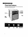
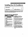
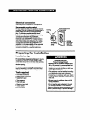
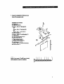
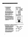
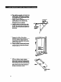
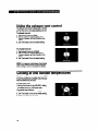
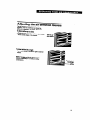
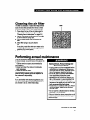
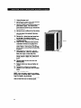
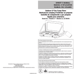
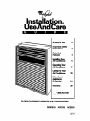
lnstakrtion,
UseAndCare
ANoteToYw
2
IFZZ?
3
Parts And
Features
4
lnstallin Your
Mordtioner
5
Operating Your
Au conditioner
17
c&i&F&~
If You Need
$$$=F~
Warranty
20
24
28
laxw53-1301
cdlwllhqlbeslion8acommonts.
SLIDER/CASEMENT
WINDOW AIR CONDlTlONERS
MODELS
ACSIOZ
ACS520
A Note To You
Thank
you for
buying
a WhirlpooP
appliance.
You have purchased a quality, worldclass home appliance. Years of engineering experience have gone
into its manufacturing. To ensure that you will enjoy many years of trouble-free operation, we have
developed this Use and Care Guide. lt is full of valuable information on how to operate and maintain
your appliance properly and safely. Please read it carefully. Also, please complete and mail the Ownership Registration Card provided with your appliance. This will help us notify you about any new information on your appliance.
Your
safety
is important
to us.
This guide contains safety symbols and statements. Please pay special attention to these symbols and
follow any instructions given. Here is a brief explanation of the use of each symbol.
This symbol will help alert you to such
dangers as personal injury, burns, fire and
1 electricalshock.
This symbol will help you avoid actions
1
Our Consumer
Assistance
Center
is toll-free,
24 hours a day.
1 ~~~~~~~~~
product
(scratches, dents, etc.)
and damage
damage to your
number,
l-80@253-1301,
lf you ever have a question concerning your appliance’s operation, or if you need service, first see “If
You Need Assistance Or Service” on page 24. If you need further help, feel free to call our Consumer
Assistance Center. When calling, you will need to know your appliance’s complete model number and
serial number. You can find this information on the model and serial number plate (see diagram on
page 4). For your convenience, we have included a handy place below for you to record these numbers,
the purchase date from the sales slip and your dealer’s name and telephone number. Keep this book
and the sales slip together in a safe place for future reference.
Model Number
Dealer Name
Serial Number
Demler Phone
Purchase Date
1
Important
l
l
l
l
safety instructions
Read all instructions before using your air
conditioner.
Complete the installation requirements as
described in the Installation Instructions.
Do not allow children to operate or play with
the air conditioner.
Do not operate the air conditioner with the
front panel removed.
Never clean air conditioner parts with
flammable fluids. The fumes can create a fire
hazard or explosion.
l FOR YOUR SAFETY l
DO NOT STORE OR USE GASOLINE OR
OTHER FLAMMABLE VAPORS OR LIQUIDS
IN THE VICINITY OF THIS OR ANY OTHER
APPLIANCE. THE FUMES CAN CREATE A
FIRE HAZARD OR EXPLOSION.
l
- SAVE THESE INSTRUCTIONS -
Help
us help
you
Please:
l Install the air conditioner in a window that will
hold the weight and secure it in accordance
with the Installation Instructions.
l Connect the air conditioner only to the proper
kind of outlet with the correct electrical supply
and grounding. (See the Installation Instructions.)
l Be sure the air conditioner is the correct size for
the area you want to cool.
l Use the air condiiioner only for its intended
purpose.
l Be sure the air conditioner is not used by
anyone unable to operate it propetfy.
l Maintain the air conditioner properly.
Also, remove the Energy Label and Buy Guide.
Use a damp cloth to take off any glue residue. Do
not use sharp instruments, flammable fluids or
abrasive cleaners. These can damage the
material.
3
PartsAnd
Features
This section contains captioned illustrations of your appliance. Use them to become familiar with where
all parts and features are located and what they look like.
Air direction
thumb wheel
ROIlbOVdO
air
lilb
(behind air
Intake panel)
FL
COIIBOI
COlltTOl
I
tisumu
Asoistmco
Centu lobphone number
Installing Your Air Condiiioner
In This
Section
PW
PWP
Mwttng m
nquirsmnb ..................-.. 5
PropsrIng fur instdauu4l ................................... 5
installing in a sliding window ......................... 5
ln.lallbIgin a crmont
window .............. .... 13
Proper installation of your air conditioner is important for proper operation and best cooling results. This
section will tell you how to meet necessary electrical requirements and how to install your air conditioner
properly into a sliding or casement style window. Please read these installation instructions, as well as
the operating and care instructions, before installing your unit.
Meeting
electrical
requirements
OBSERVE ALL LOCAL CODES AND
ORDINANCES.
Elactrlul Shock and
Person81 Injury Hazard
l Electrical ground is required on this
appliance.
l DO NOT modify the power supply cord
plug. lf it does not fit the outlet, have a
proper outlet installed by a qualified
electrician.
l DO NOT have a fuse in the neutral or
grounding circuit. A fuse in the neutral or
grounding circuit could result in an
electriial shock
l DO NOT use an extension cord with this
appliance.
l Check with a qualified electrician if you
are in doubt as to whether the appliance
is properly grounded.
Failure to follow these instructions could
resutt in electrical shock, serious injury
or death.
DO NOT, UNDER ANY CIRCUMSTANCES,
REMOVE THE POWER SUPPLY CORD
GROUNDING PRONG.
NOTE: lf codes permit and a separate grounding
wire is used, it is recommended that a qualified
electrician determine that the grounding path is
adequate and not interrupted by plastic, nonmetallic gaskets or other insulating materials.
Receptacle
wiring
Receptacle wiring should be a minimum of
14gauge. Use copper wire only. It is the responsibility of the consumer to provide proper and
adequate receptacle wiring, installed by a
qualified electrician. Observe the National
Electrical Code and all local governing codes and
ordinances.
Electrical
requirements
A 115 volt (103.5 minimum, 126.5 maximum),
60 Hertz, AC only, 15 ampere fused electrical
supply is required. A time delay fuse or time
delay circuit breaker is also required. A separate
circuit, sewing only this appliance, must be
provided.
5
Electrical
connection
Electrical ground is required on this appliance.
Recommended groundlng method
For your personal safety, this appliance must bs
grounded. This air conditioner is equipped with a
power supply cord with a 3prong grounding
plug. To minimize possible electrical shock
hazard, the cord must be plugged into a mating
3prong grounding-type wall receptacle,
grounded in accordance with the National
Electrical Code (ANSI/NFPA 70-latest version)
and all local codes and ordinances. If a mating
3-prong groundingtype wall receptacle is not
available, it is the responsibilii of the consumer
to have a properly grounded 3-prong wall
receptacle installed by a qualified electrician.
Preparing
Installation
for installation
tips
For wood-frame cnement windowe: It may be
necessary to construct a frame, using at least
1-inch thick wood, with a 15%inch wide opening.
Fasten frame securely and seal it into the
window opening.
For brick or cement bulkflng conetruction: It
may be necessary to provide a wood stool strip
under the air conditioner for mounting purposes.
Tools
l
l
l
l
l
l
l
l
Poww
required
Flat-head screwdriver
Phillips-head screwdriver
Carpenter’s level
Tape measure
Fine tooth saw
Electric or hand drill
%-inch drill bit
%-inch drill bit
Pereonel Injury and
Product Damage Hazard
l Because this air conditioner weighs about
88 to 105 pounds, it is recommended that
you have someone help you when you
install your new unit and that you both use
proper lifting techniques.
l This appliance must be installed according
to all applicable codes and ordinances.
l Handle the air conditioner with care. Watch
out for the sharp metal fins on the front and
rear coils.
l Be sure your air conditioner does not fall
during installation.
l Do not use the water collected in the unit
for drinking purposes. lt is not sanitary.
Failure to follow the above precautions could
resull in personal injury or product damage.
1. Unpack the installation kft. Make sure you
have all the necessary parts.
In~tdatkm kit contenta:
A Platform (1)
B. Adjustment bolt (1)
C. Screw - #10 x 2%’ flat-head (2)
OR
Screw - #lO x 1%’ pan-head (2)
OR
Screw - #lO x 1’ pan-head (2)
D. Safety bracket (1)
E. Screw - #8-32 x o/4’self-threading (7)
F. Track seal (1)
G. Foam seal strip/Sash seal (1)
H. Side channel seal (1)
I. Plastic window panel (1)
J. Window locking bracket (1)
K. Hex flange nut - l/4’ (1)
L. Screw - #8 x W’ round wood-head (8)
M. Support brace (1)
NOTE: Use the scale at the right to measure the
length of your screws. This will come in handy
when separating screws for installation.
7
2. Choore a proper size window.
l
15% inches minimum width
l
18% inches maximum width
(for casement windows)
l
21%e inches minimum height
(with window panel retainer)
l
20% inches minimum height
(window panel retainer removed)
l
40 inches maximum height
NOTE: The height measurement must be of
an unobstructed opening above the mounting
platform. In some cases, due to a variety of
stop and track arrangements, the above
dimensions may vary slightly. lf necessary, the
installation can be made by altering the
window jambs. (See “Alternate window jamb
applications” on page 12.)
in a sliding
1. Attach support brece to platform as shown.
Use the adjustment bolt and hex flange nut to
complete the assembly. Choose the slot and
adjustment bott hole locations that will create a
45’ angle between the platform and the
support brace. Try the assembly in the window
to determine if the platform will rest properly
and allow the proper slope (?&inch lower on
outside). Without the proper slope, water could
drip into your home and cause water damage.
NOTE: lf you are planning to use a sidingprotection board (see Step 5) on the outside of
your house, hold the board in place when
testing the assembly in the window.
8
minimum
Width
maximum
D
Width
(cwemannt
windows)
20’KI illcha
minimum
height
46 inchw
maximum
haight
I
I
3. Choose the prof~r window location.
Choose a window that will allow the cooled air
to flow freely and directly into the room(s) you
want to cool. Remember, it is difficult to move
air around comers. Also, choose a window
that is within 8 feet of an electrical outlet. (See
“Meeting electrical requirements” on pages 5-6
for receptacle and wiring needs.) Do not we
en extension cord.
Installing
16%in&w
15%inch08
4
window
4
1
2. Men~re and lightly mark e line 8VAnches
from the right window jamb.
NOTE: lf any sash stop protrudes more than
1 inch from the side window jambs, the
8W4nch measurement must be increased
accordingly. Screen and storm window frames
may also require adjustments to the measurement.
3. Center the platform ueembfy on the line
with the inside platform tab pressed against
the inside edge of the window track. Using the
holes in the platform as a guide, mark and drill
two !&-inch diameter holes. Drill holes in
either track or stool.
Proper Dammge Hazard
Be sure the wood stool or window track is
securely attached to the building construction. Use longer screws into the subframing ff necessary.
Failure to follow the above precaution could
result in damage to the window or air
conditioner.
Centor pl&orm uoembly on the
line with pl&orm bb prwud
eghst window tmclr
Alternate screw bc8Uon PI&form
IMina
on atool
bb
4. Peel off the protecthro backing from the
track seal. Apply seal to the room side of the
window track. The center of the seal strip
should coincide with the line marked in Step 2.
The two screw holes drilled in Step 3 should
be directly above the seal strip in the inner
track
5. Securely attach a riding-protection
board
to the side of the house.
OR
To avoid permanent siding damage, attach the
siding-protection board to the base of the
support brace as shown.
NOTE: The siding-protection board should be
long enough to span 2 wall studs.
9
6. Place platform aeeembly, with platform tab
against inside of window track, and attach it
to the window jamb. Use appropriate length
screws (item C on page 7).
7. Adjust the platform aeeembfy so that the
outside edge is %-inch lower than the
inside edge. This ensures proper water
drainage from the air conditioner.
8. Level the platform aeeembly from sideto-side. Also, make sure the window track
is level. Use leveling shims as necessary to
ensure the air conditioner will be level from
side-to-side.
9. Measure the height of the window
opening from the top of the platform
assembly. Subtract 20% inches (the height
of the air conditioner cabinet). Mark this
measurement on the plastic window paneC
along the longer side.
10. Clamp the plaetic window panel between
a board and a work table and cut along the
cutting line with a fine tooth saw. Remove
any burrs with a file.
11. Lift the panel frame from the side channels
of the air conditioner cabinet. Slide the
plastic window panel into the frame with the
smooth side to the outside. Slide the panel
frame assembly back into the side channels
of the air conditioner cabinet. Make sure the
plastic window panel is firmly enclosed on
all sides by the retainer grooves.
10
Outside odgo
is %-in&
loww nlul
inoido.
+
Put platform
Measure
bebnco md
subtract
20% in&se.
12. Cut l kle channel eeal into 2 equal lengths.
Remove the protective backing and apply it
to the rear side of the cabinet side channels,
starting just below the panel frame assembly. Pinch off excess length so the seal is
even with the bottom of the cabinet side
channel.
Apply w-thor
swl to oich
chne& juot
beIowodg@of
pad frame.
13. Remove the air intake penel and front
Panel frame First, press down on the top
edge of the air intake panel and tilt it toward
you. Lit it up to release the bottom spring
clips. Next, remove the 2 Phillips-head
screws holding the front panel frame in
place. Finally, press down on the top edge
of the front panel frame, tilt lt forward, and
lift it up off the bottom spring clips.
NOTE: Do not push or pull on the air
direction louvers.
3. Promsdown and tilt forward to
remove front penal fmmo.
l.Preudown
14. Piece the air conditioner in the window
opening. It should sit on the platform
assembly so that the window panel frame
and the cabinet side channels are against
the top and side window jambs.
11
15. Slide the inner window each firmly
against the side of the cabinet. Make sure
not to peel the seal strips from the window
track and cabinet side channels. If the panel
frame does not fit snugly to the inner
window sash, secure the panel frame to the
sash with #8 x %-inch wood screws or #832 x %-inch self-threading screws. Use the
partially plugged holes in the panel frame.
For metal or plastic window sashes or
jambs, drill H-inch pilot holes for the selfthreading screws.
NOTE: When installing screws in the
window sash, be sure not to interfere with
the glass inside the sash retaining channel.
6lids inm
window Bmoh
lirmly wnst
Cdhld
InrW ufoty braket
16. Hook the safety bracket over the base of
the unft and fasten it to the front of the
platform assembly. Use a #8-32 x %-inch
self-threading screw.
NOTE: The bracket prevents movement of
the air conditioner (either in or out) after
completing the installation.
17. Stuff the foam aeal l trip/aaah real
between the vertical sash and the window
glass.
16. UK the window locking brmket to lock
the inner window sash to the base of the
outer window sash. Use one It8 x %-inch
wood screw or #8-32 x %-inch self-threading
screw. (See illustration.)
19. Replete the air conditioner front panel
frame and air intake panel. Make sure you
replace the 2 screws that hold the front
panel frame in place before you replace the
air intake panel.
Alternate
window
applications
jamb
To install in windows having no flanges or wood
stops on the top and side jambs, the channels
and panel frame must fit against a mating flange
(or l&inch max. thick angle) attached to the
window jambs. Figure A shows this angle
installed. Figures B CLC show alternate treatments. On the sash side of the opening, the
leading comer of the inner sash becomes the
flange. You can purchase the angle strip locally.
12
A
AddM*to
-stop
C
Add16- or lawge
we
Installing
in a casement
NOTE: Open the window the maximum amount
to allow for clearance of the cabinet. The crank
handle should be removed to allow the platform
to be fastened to the jamb. If the window cannot
open far enough (more than 15% inches) for the
cabinet to clear the window, remove the window
entirely by drilling out the rivets. Bolts can serve
as the pivots in the future.
1. Attech support brace to platform as shown.
Use the adjustment bolt and hex flangs nut to
complete the assembly. Choose the slot and
adjustment bolt hole locations that will create a
45’ angle between the platform and the
support brace. Try the assembly in the window
to determine if the platform will rest properly
and allow the proper elope (?&inch lower on
outside).
NOTE: lf you are planning to use a skfingprotection board (see step 5) on the outside of
your house, hold the board in place when
testing the assembly in the window.
2. Drill a Wclnch diameter pikt hole in the
window jamb an equal distance from each side
of the jamb and %-inch up from the window
sill. lf the hole coincides with the window lever
slot in the jamb bottom, an additional hole will
have to be drilled through the platform edge
and the window jamb to miss this slot.
3. Peel off the protective backing from the
track seal and stick the seal to the window sill
on the outside of the bottom jamb.
4. Screw the pletform assembly to the window
jamb through the pilot hole you drilled in Step
2. Use a #8 x %-inch self-threading screw.
window
To avoid the crank handle and window clearance
problems, the unit can be installed in a stationary
sash section. However, the horizontal mullion
and the 2 glass panels must be removed before
installation.
Equal df~tance from both l ickr
Appiytmcksuitotboouteido
dg~ of UM bottom window jamb.
Track seal
-
13
5. Adjust the piatforrn ueembfy so that the
rear of the air conditioner will be %-inch lower
than the front. This ensures proper water
drainage from the air conditioner.
NOTE: A projection below the base of the air
conditioner will require the rear of the platform
to be %a-inch lower than the front to create the
3/ibinch slat from front to rear.
Reu is et beet
7/t0-in& lower
6. Securely ettach a ridingprotection
board
to the side of the house where the platform
assembly hits the house. The siding-protection
board should be long enough to span 2 wall
studs.
d
7. Meaeure the height of the window opening
from the top of the platform assembly.
Subtract 20% inches (the height of the air
conditioner cabinet). Mark this measurement
on the plastic window panel-along the longer
side.
6. Clamp the pleetlc window penel between a
board and a work table and cut along the
cutting line with a fine tooth saw. Remove any
burrs with a file.
9. Lii the panel frame from the side channels of
the air conditioner cabinet. Slide the plastic
window panel into the frame with the smooth
side to the outside. Slide the panel frame
assembly back into the side channels of the
air conditioner cabinet. Make sure the plastic
window panel is firmly enclosed on all sides by
the retainer grooves.
14
Feeten eidingprotmtion bored to
the heuee eiding.
10. Cut ride channel eeal into 2 equal lengths.
Remove the protective backing and apply it
to the rear side of the cabinet side channels,
starting just below the panel frame assembly. Pinch off excess length so the seal is
even with the bottom of the cabinet side
channel.
11. Remove the air inteke panel and front
Penel fmme. First, press down on the top
edge of the air intake panel and tilt ft toward
you. Lift it up to release the bottom spring
clips. Next, remove the 2 phillips-head
screws holding the front panel frame in
place. Finally, press down on the top edge
of the front panel frame, tilt it forward, and lift
it up off the bottom spring clips.
NOTE: Do not push or pull on the air
direction louvers.
12. Piece the air conditioner in the window
opening. It should sit on the platfom-r
assembly so that the window panel frame
and the cabinet side channels are against
the top and side window jambs. Side
channels should overlap side window jambs
equally.
3. Prmu down and tilt forward to
romovo front pmol hamo.
l.Pmedown
enduft
toward to
remove air
lntako panel.
13. Drill two %-inch diameter pilot holee in
the top window jamb in line with the partially
plugged holes in the panel frame. Secure
the panel frame to the window jamb wfth two
#8-32 x %-inch self-threading screws. lf
additional holding is necessary, two screws
may be used on the sides of the panel frame
as well.
14. Drill two ecrew4eerance holee in the
cabinet side channels (near bottom) and two
F&-inch diameter pilot holes in the side
window jambs. Secure the cabinet side
channels to the window jambs wfth two t832 x %-inch self-threading screws. When
doing this, be careful not to twist the side
channel seals with the screws.
NOTE: The insertion of these screws will
prevent the air conditioner from being
pushed into the room.
15. Replete the air conditioner front panel
frame. Make sure to replace the 2 screws
that hold the panel in place. Do not push or
pull on the front panel louvers.
16. Replete the air intnke panel and air filter.
Snap air filter into back of air intake panel
before snapping air intake panel into place.
16
601
Operating Your Air
Conditioner
In This
Section
Stmrtingyour air conditionw
PW
Pm
........................... 17
thing UIO exhaust vent cunlrol ....................... 16
Cooling at low outida
twnperaturu
A@mUng the air direction kuvm
...... ..... 16
...... ......... 18
In order to obtain the best possible results from your air conditioner, it is important that you operate it
properly. This section will tell you how to do just that.
Starting
your air conditioner
1. Set Exhaust Control to CLOSED for maximum cooling performance.
2. Set Fan Control to the desired setting.
QUIET COOL ............. ..... for sleeping cotiort
REGULAR COOL ............. . for normal cooling
MAX COOL .................... for maximum cooling
FAN ONLY ........... ....... for circulating room air
when no cooling is desired
3. Turn the Thermostat Control to the desired
setting. You can adjust the air conditioner’s
cooling performance by turning the Thermostat Control clockwise for more cooling or
counterclockwise for less cooling. You will
need to experiment to find the setting which
suits you best.
Electrical Shock Hazard
Plug unit only into grounded electrical outlet.
l Do not use an extension cord,
l Do not operate unit with front panel removed.
Failure to follow the above precautions could
result in electrical shock or personal injury.
l
NOTE: If you turn your air conditioner off or if
the compressor turns off when lowering the
Thermostat Control, wait at least 3 minutes
before turning it back on. Doing this keeps the
air conditioner from blowing a fuse or tripping a
circuit breaker.
17
Using
the exhaust
vent control
The Exhaust Vent Control draws stale or smoky
air from the room or circulates existing rmrn air.
To exhauot room air:
1. Set Exhaust Control to OPEN.
2. Set Fan Control to desired setting. If no
cooling is desired, set Fan Control to FAN
ONLY.
3. Set Thermostat Control to desired setting.
To circulate room air:
1. Set Exhaust Control to CLOSED.
2. Set Fan Control to desired setting. If no
cooling is desired, set Fan Control to FAN
ONLY.
3. Set Thermostat Control to desired setting.
NOTE: For maximum performance, the Exhaust
Vent Control must be in the CLOSED position
when cooling or room air circulation is desired.
Cooling
at low outside
When the outside temperature drops below 70°F
and the air conditioner is cooling, frost may form
on the coils behind the air intake panel. This will
block the airflow into the room.
To defrost the coik:
l Set the Fan Control to the FAN ONLY setting
and allow unit to run until frost is gone.
To prevent frost build-up:
1. Set the Fan Control to desired COOL setting.
2. Set Thermostat Control to the middle setting.
3. Make sure all louvers are open.
18
temperatures
Adjusting
the air direction
louvers
The air direction louvers control the airflow
direction. Your air conditioner can direct the
airflow in 4 directions - up, down, left or right.
To direct airflow up or down:
Tilt the louvers up or down with the tabs located
at the outside edges of the louvers.
l
ThhXup/
down aim0w
To direct airflow left or right:
Turn thumb wheel to the left or right for desired
airflow.
l
NOTE: The tabs and thumb wheels can be
adjusted separately for a variety of airflow
combinations.
19
Caring For Your Air
Conditioner
In This
Section
Paw
Pm
l uunda ...2 3
Cloming Iho air infako ~anol .......................... .20
Undaratulding
normd o~ualing
tho air filter ...... . ................................ 21
.................... .21
Puformlng l nnud mdnbnnca
swing nugy
................................................ 23
clouling
Proper maintenance of your air conditioner will
help ensure longer lie and lower operating costs.
This section will tell you how to clean your air
conditioner and perform annual maintenance.
You can always call your authorized Whirlpool@
servicing dealer for an annual check-up.
l
l
Cleaning
the air intake
Electrical Shock and Fire Hazard
Unplug power cord from receptacle before
cleaning unit. Failure to do so could result
in electrical shock or personal injury.
Do not use flammable fluids, solvents,
abrasive cleaners or strong detergents.
Fire or product damage could resuft.
panel
1. Unplug the power cord.
2. Remove the air intake panel from unit for
cleaning. Press down at top of panel to
release it from the front panel frame.
3. Tilt top of panel toward you.
4. Lii panel up and away from the bottom
spring clips.
5. Remove the air filter from the back side of
the air intake panel and clean it separately.
(See “Cleaning the air fiftef on page 21.)
6. Clean air intake panel with warm water, mild
soap or detergent and a soft cloth. Rinse
and dry thoroughly.
7. Wipe control panel clean wfth a soft, dry
cloth.
6. Replace air fifter.
9. Replace the air intake panel. Locate bottom
of panel on the spring clips. Press down on
top edge of panel and push it toward the
unit to secure the upper tabs.
10. Plug in the power cord.
20
Push down
end tilt
forwerd
Air i&ko
pnd
Cleaning
the air filter
The fifter is cleanable. A clean filter helps remove
dust, lint and other particles from the air. Check
every two weeks to see if fifter needs cleaning.
1. Press down the top of the air intake panel to
release it from the front panel frame. (See
“Cleaning the air intake panel” on page 20.)
2. Tift top of air intake panel toward you and lift it
up off the bottom spring clips.
3. Turn air intake panel over and remove air
fifter.
4. Clean fifter using a vacuum cleaner.
OR
lf very dirty, wash fitter wfth warm water and a
mild detergent. Air dry filter thoroughly before
replacing in air intake panel.
5. Replace air filter and air intake panel.
Performing
annual
maintenance
Your air conditioner needs annual maintenance
to ensure steady, top performance throughout the
year.
Call the service company recommended by
your dealer to:
l Inspect and clean the coils and condensate
water passages.
l Check fan and fan motor.
The compressor and fan motor are sealed and
need no oiling. Expense of annual inspection is
the customer’s responsibility.
OR
lf you are familiar wfth electrical appliances, you
can do the cleaning and maintenance yourseff. ff
you choose to do so, follow these steps.
Electrical Shock, Product Damage and
Penonal Injury Hazard
l Unplug power cord from receptacle before
performing any maintenance. Be sure no
liquid gets into the motor, electrical control
box or compressor electrical terminals.
l Do not lift, push or pull any white beaded
foam (expanded polystyrene) parts.
l Because your air conditioner weighs from
88 to 105 pounds, it is recommended that
you have someone help you when you
remove and re-install your unit and that you
both use proper lifting techniques.
l Handle the air conditioner with care. Watch
out for the sharp, metal fins on the front
and rear coils.
l Do not use the collected water for drinting
purposes. lt is not sanitary.
Failure to follow the above precautions could
result in electrical shock, product damage or
personal injury.
continued on next page
21
1. Unplug the power cord.
2. Remove the air intake panel. (See “Cleaning
the air intake paner on page 20.)
3. Remove 2 Phillips-head screws holding front
panel frame in place. Then remove front
panel frame the same way you removed the
air intake panel.
4. Remove the air conditioner from the window.
5. Remove the 6 slotted hex-head screws
along the base of the cabinet (3 per sideas shown).
6. Remove the 1 slotted hex-head screw from
the left side of the cabinet (as shown).
7. Holding the cabinet on both sides, carefully
lift cabinet off base.
6. Wrap the motor, electrical control box and
compressor terminal box in plastic film to
make sure no water or other liquids get
inside. Water or other liquids could damage
the insulation and cause serious mechanical
problems.
9. Clean and hose out the base, coils and
condensate pans. Clean air conditioner at
least once a year or more often if the
condenser coils and pans collect dirt, sand,
leaves, insects or algae. Also, clean the air
conditioner if you detect an odor coming
from it.
10. Remove plastic film from the motor and
electrical parts.
11. Replace cabinet over base and tighten all
screws.
12. Reinstall air conditioner in the window.
13. Replace the air intake panel and front panel
frame.
14. Plug in the power cord.
NOTE: It is a good idea to wait 24 hours before
starting the air conditioner again. Doing so allows
time for all areas to dry thoroughly.
The water from rainfall or from normal operation
does not harm the motor or electrical parts.
22
6crm
Understanding
normal
operating
sounds
When your air conditioner is operating normally,
you will hear sounds such as:
l Droplets of water hitting the condenser, causing
a “pinging’ or “clicking” sound. Water droplets
help to cool the condenser.
l Air movement from the fan, especially on high
fan speed settings.
l Clicks from the thermostat cycle.
Sounds also may be caused by house constructiorwruch as vibration of the unit due to wall
construction or unsteady window mounting area.
Saving
energy
You can help save energy by following the tips
below.
l Improve your home’s insulation. Seal all doors
and windows. Close the fireplace flue.
l Close all blinds and drapes on sunny sides of
the house. Add window awnings.
l Keep the air filter clean.
l Do not block the airflow with drapes or furniture.
l Ventilate the attic. High temperatures in the
attic add to the air conditioner’s cooling load.
l Try not to use heat-producing appliances during
the hottest part of the day.
l Turn off lights and appliances when they are
not needed.
l Keep heat registers and cool-air returns closed.
l Use exhaust venting fans when cooking, doing
laundry or bathing.
23
If You Need Assistance
service
Or
This section is designed to help you save the cost of a service call. Part 1 outlines possible problems,
their causes, and actions you can take to solve each problem. Parts 2 and 3 tell you what to do if you
still need assistance or service. When calling our Consumer Assistance Center for help or calling for
service, please provide a detailed description of the problem, your appliance’s complete model and
serial numbers and the purchase or installation date. (See page 2.) This information will help us respond
properly to your request.
1. Before
calling
for assistance
. ..
Performance problems often result from little things you can find and fix without tools of any kind. Please
check the chart below for problems you can fix. lt could save you the cost of a service call.
PROBLEM
Air conditioner
will not run
POSSIBLE CAUSE
Unit is not plugged into a live
circuit with proper voltage.
The Fan Control is set to OFF.
The Thenostat Control is not
set correctly.
A household fuse has blown or
a circuit breaker has tripped.
The local power has failed.
SOLUTION
Plug unit into a live circuit with proper
voltage.
Set the Fan Control to a setting other
than OFF.
Set the Thermostat Control to a setting
cooler than the room temperature.
Replace fuse or reset circuit breaker.
Wait for power to be restored.
Unit blowe
household f uoaa
or trlpr circuit
bretaker
A time-delay fuse is not being
used.
An extension cord is being
used.
The unit was just turned off and
on again.
Replace fuse with a time-delay fuse of
the correct capacity.
Do not use an extension cord to run your
air conditioner.
Wait three minutes after turning unit off
before trying to restart it.
Unit turn8 on
and off, or does
not cooUheM
room
The filter is dirty.
The coils (evaporator [inside]
and condenser [outside]) are
dirty.
There is excessive moisture or
heat in the room.
Clean the filter. (See page 21.)
Clean the coils. (See pages 21-22.)
The fan speed setting is too
low.
The Thermostat Control is not
set correctly.
ke forms on
coils behind air
intake panel
24
Outdoor temperature is below
7O’F.
It will take longer for the unit to cool or
heat a room when there is excess
moisture or heat (open cooking vessel,
shower, etc.).
Set Fan Control to a higher setting.
Set the Thermostat Control to a cooler
setting.
Defrost coils. (See “Cooling at low
outside temperatures” on page 16.)
2. lf you need
assistance
...
Cdl Whlrlpool Coneumer Aaeiatance Center
telephone number. Diil free from anywhere in
the U.S.A.:
1-800-253-l 301
and talk with one of our trained consultants. The
consultant can instruct you in how to obtain
satisfactory operation from your appliance or, if
service is necessary, recommend a qualified
service company in your area.
lf you prefer, write to:
Mr. William Clark
Consumer Assistance Representative
Whirlpool Corporation
2000 M-63
Benton Harbor, MI 49022
Please include a daytime phone number in your
correspondence.
3.
If you need
service
4.
replace-
FSP is a registered trademark of Whirlpool
Corporation for quality parts. Look for this symbol
of quality whenever you need a replacement part
for your Whirlpool appliance. FSP replacement
parts will fit right and work right. because they
are made to the same exacting specifiiations
used to build every new Whirlpool appliance.
To locate FSP replacement parts in your area,
refer to Step 3 above or call the Whirlpool
Consumer Assistance Center number in Step 2.
5. lf you are not satisfied
how the problem
was
solved . . .
l
...
Whirlpool has a nationwide network of authorized
Whirlpoor
service
companies. Whirlpool service
technicians are trained to fulfill the product
warranty and provide after-warranty service,
anywhere in the United States. To locate the
authorized Whirlpool service company in your
area, call our Consumer Assistance Center
telephone number (see Step 2) or look in your
telephone directory Yellow Pages under:
If you need FSP
ment parts . . .
l
l
with
Contact the Major Appliance Consumer Action
Panel (MACAP). MACAP is a group of independent consumer experts that voices consumer views at the highest levels of the major
appliance industry.
Contact MACAP only when the dealer,
authorized servicer and Whirlpool have failed
to resolve your problem.
Major Appliance Consumer Action Panel
20 North Wacker Drive
Chicago, IL 60606
MACAP will in turn inform us of your action.
25
vvHlF?LPooc
Room Air Conditioner Warranty
LENGTH OF WARRANTY
WHIRLPOOL WILL PAY FOR
FULL ONE-YEAR WARRANTY
FSPO replacement parts and repair labor to correct defects in
materials or workmanship.
From Date of Purchase
FULL FIVE-YEAR WARRANTY
From Date of Purchase
FSP replacement parts and repair labor to correct defects in
materials or workmanship in the sealed refrigeration system.
These parts are:
1. Compressor 4. Drier-strainer
2. Evaporator 5. Connecting tubing
3. Condenser
WHIRLPOOL WILL NOT PAY FOR
A Sewice calls to:
B.
C.
D.
E.
1. Correct the installation of your air conditioner.
2. Instruct you in how to use your air conditioner.
3. Replace house fuses or correct house wiring.
4. Clean or replace the air filter.
Pickup and delivery. Your air conditioner is designed to be repaired in the home.
Damage to your air conditioner caused by accident, misuse, fire, flood, acts of God or use of
products not approved by Whirlpool.
The removal and reinstallation of your air conditioner if it is installed in an overhead or other
inaccessible location or not installed in accordance with published installation instructions.
Repairs to parts or systems caused by unauthorized modifications made to the appliance.
Service under the full warranties
must be provided by an authorized
co?
Whirlpool service company.
WHIRLPOOL CORPORATION SHALL NOT BE LIABLE FOR INCIDENTAL OR CONSEQUENTIAL
DAMAGES. Some states do not allow the exclusion or limitation of incidental or consequential damages,
so this limitation or exclusion may not apply to you. This warranty gives you specific legal rights, and you
may also have other rights which vary from state to state.
Outside the United States, a different warranty may apply. For details, please contact your authorized
Whirlpool distributor or military exchange.
lf you need service, first see the “Assistance or Service” section of this book. After checking
“Assistance or Service,” additional help can be found by calling our Consumer Assistance Center
telephone number, l-600-253-1301, from anywhere in the U.S.A.
PART NO. QSWPL-DO2I 1164146 Rev. A
0 1sM whirlpool
corpontlon
@ Fl+lmd
Trad.mwk
d WhIrlpod.
U.SA.
Piintd
h U.SA