1
Agilent N9360A
Multi UE Tester
W-CDMA User Manual
Agilent Technologies
Notices
© Agilent Technologies, Inc. 2008
Manual Part Number
No part of this manual may be reproduced
in any form or by any means (including
electronic storage and retrieval or translation into a foreign language) without prior
agreement and written consent from
Agilent Technologies, Inc. as governed by
United States and international copyright
laws.
N9360-90701
Edition
Third Edition, March 2008
Printed in Malaysia
Agilent Technologies Microwave Products
(Malaysia) Sdn. Bhd.
Bayan Lepas Free Industrial Zone
11900 Penang, Malaysia
Warranty
The material contained in this document is provided “as is,” and is subject to being changed, without notice,
in future editions. Further, to the maximum extent permitted by applicable
law, Agilent disclaims all warranties,
either express or implied, with regard
to this manual and any information
contained herein, including but not
limited to the implied warranties of
merchantability and fitness for a particular purpose. Agilent shall not be
liable for errors or for incidental or
consequential damages in connection
with the furnishing, use, or performance of this document or of any
information contained herein. Should
Agilent and the user have a separate
written agreement with warranty
terms covering the material in this
document that conflict with these
terms, the warranty terms in the separate agreement shall control.
Technology Licenses
The hardware and/or software described
in this document are furnished under a
license and may be used or copied only in
accordance with the terms of such license.
Restricted Rights Legend
defined in FAR 2.101(a) or as “Restricted
computer software” as defined in FAR
52.227-19 (June 1987) or any equivalent
agency regulation or contract clause. Use,
duplication or disclosure of Software is
subject to Agilent Technologies’ standard
commercial license terms, and non-DOD
Departments and Agencies of the U.S.
Government will receive no greater than
Restricted Rights as defined in FAR
52.227-19(c)(1-2) (June 1987). U.S. Government users will receive no greater than
Limited Rights as defined in FAR 52.227-14
(June 1987) or DFAR 252.227-7015 (b)(2)
(November 1995), as applicable in any
technical data.
Safety Notices
CAUTION
A CAUTION notice denotes a hazard. It calls attention to an operating procedure, practice, or the like
that, if not correctly performed or
adhered to, could result in damage
to the product or loss of important
data. Do not proceed beyond a
CAUTION notice until the indicated
conditions are fully understood and
met.
WA R N I N G
A WARNING notice denotes a
hazard. It calls attention to an
operating procedure, practice, or
the like that, if not correctly performed or adhered to, could result
in personal injury or death. Do not
proceed beyond a WARNING
notice until the indicated conditions are fully understood and
met.
If software is for use in the performance of
a U.S. Government prime contract or subcontract, Software is delivered and
licensed as “Commercial computer software” as defined in DFAR 252.227-7014
(June 1995), or as a “commercial item” as
N9360A Multi UE Tester W-CDMA User Manual
ii
Preface
Thank-you for purchasing the Agilent N9360A Wideband Code Division
Multiple Access (W-CDMA) option. This option is the W-CDMA software
for the N9360A Multi UE Tester.
• Before using the tester, the user is advised to read this manual
carefully to ensure correct usage and also to fully utilize the tester
capability.
• This manual is a reference document and the user is advised to keep it
carefully for future reference.
• The manual includes the characteristics of W-CDMA, the tester
operation, test procedures and screen references.
• Refer to the N9360A Multi UE Tester Installation Guide for information
regarding installation and details of the tester. Refer also to the
N9360A GSM Option User Manual for information about the test
functions of Global System for Mobile communication (GSM) and the
N9360A cdma2000 Option User Manual for information about the test
functions of Code Division Multiple Access (cdma2000).
Notation
The following notations are used in this manual:
• Softkey
: indicates a softkey;
• [Screen Name]
: indicates a screen name;
• Tester/tester
: indicates the N9360A Multi UE Tester.
Notices
• The information contained in this manual is subjected to change with
notice.
• The screens of user interface (UI) and values on the screens used in
this manual may be different from actual screens.
• No part of this manual may be reproduced either mechanically,
electronically or otherwise, without permission from Agilent
Technologies, Inc.
N9360A Multi UE Tester W-CDMA User Manual
iii
Trademarks
• Ethernet is the registered trademark of the Xerox Corporation.
• EPSON is the registered trademark of the EPSON Corporation.
• cdma2000® is a registered trademark of the Telecommunications
Industry Association (TIA-USA).
• Other product names and companies used herein are trademarks or
registered trademarks of their respective companies or Agilent
Technologies, Inc. For registered trademarks, the trademarks symbols
® and ™ are omitted in this manual.
iv
N9360A Multi UE Tester W-CDMA User Manual
DECLARATION OF CONFORMITY
According to EN ISO/IEC 17050-1:2004
Generic example
Manufacturer’s Name:
Manufacturer’s Address:
Agilent Technologies Microwave Products (M) Sdn. Bhd
Bayan Lepas Free Industrial Zone,
11900, Bayan Lepas, Penang, Malaysia
Declares under sole responsibility that the product as originally delivered
Product Name:
Models Number:
Product Options:
Multi UE Tester
N9360A-134, N9360A-135 (GS8210)
This declaration covers all options of the above product(s)
complies with the essential requirements of the following applicable European Directives, and
carries the CE marking accordingly:
Low Voltage Directive (2006/95/EC)
EMC Directive (2004/108/EC)
and conforms with the following product standards:
EMC
Standard
Limit
IEC 61326:2002 / EN 61326:1997+A1:1998+A2:2001+A3:2003
CISPR 11:1990 / EN55011:1990
IEC 61000-4-2:1995 / EN 61000-4-2:1995
IEC 61000-4-3:1995 / EN 61000-4-3:1996
IEC 61000-4-4:1995 / EN 61000-4-4:1995
IEC 61000-4-5:1995 / EN 61000-4-5:1995
IEC 61000-4-6:1996 / EN 61000-4-6:1996
IEC 61000-4-11:1994 / EN 61000-4-11:1994
Class A Group 1
4 kV CD, 8 kV AD
3 V/m, 80-1000 MHz
0.5 kV signal lines, 1 kV power lines
0.5 kV line-line, 1 kV line-ground
3 V, 0.15-80 MHz
1 cycle / 100%
Canada: ICES-001:2004
Australia/New Zealand: AS/NZS CISPR11:2004
The product was tested in a typical configuration with Agilent Technologies test systems.
Safety
IEC 61010-1:2001 / EN 61010-1:2001
Canada: CAN/CSA-C22.2 No. 61010-1-04
USA: ANSI/UL 61010-1:2004
190695
This DoC applies to above-listed products placed on the EU market after:
20-Jun-2008
Tay Eng Su
Date
Quality Manager
For further information, please contact your local Agilent Technologies sales office, agent or distributor,
or Agilent Technologies Deutschland GmbH, Herrenberger Straße 130, 71034 Böblingen, Germany.
Template: A5971-5302-2, Rev. E
N9360A Multi UE Tester W-CDMA User Manual
N9360A_134_ 135
DoC Revision 1.0
v
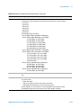
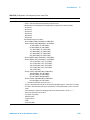
Product Regulations
EMC
Performance Criteria
IEC 61326-1:2002 / EN 61326-1:1997+A1:1998+A2:2001+A3:2003
CISPR 11:1990 / EN 55011:1990 – Group 1 Class A
IEC 61000-4-2:1995 / EN 61000-4-2:1995 (ESD 4kV CD, 8kV AD)
IEC 61000-4-3:1995 / EN 61000-4-3:1996 (3V/m, 80% AM)
IEC 61000-4-4:1995 / EN 61000-4-4:1995 (EFT 0.5kV line-line, 1kV line-earth)
IEC 61000-4-5:1995 / EN 61000-4-5:1995 (Surge 0.5kV line-line, 1kV line-earth)
IEC 61000-4-6:1996 / EN 61000-4-6:1996 (3V, 0.15~80 MHz, 80% AM, power line)
IEC 61000-4-11:1994 / EN 61000-4-11:1994 (Dips 1 cycle, 100%)
B
A
A
A
A
A
Canada: ICES-001:2004
Australia/New Zealand: AS/NZS CISPR11:2004
Safety
IEC 61010-1:2001 / EN 61010-1:2001
Canada: CAN/CSA-C22.2 No. 61010-1-04
USA: ANSI/UL 61010-1:2004
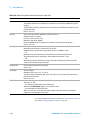
Additional Information:
The product herewith complies with the essential requirements of the Low Voltage Directive 2006/95/EC and the
EMC Directive 2004/108/EC and carries the CE Marking accordingly (European Union).
1
Performance Criteria:
A Pass - Normal operation, no effect.
B Pass - Temporary degradation, self recoverable.
C Pass - Temporary degradation, operator intervention required.
D Fail - Not recoverable, component damage.
N/A – Not applicable
Notes:
Regulatory Information for Canada
ICES/NMB-001:2004
This ISM device complies with Canadian ICES-001.
Cet appareil ISM est confomre à la norme NMB-001 du Canada.
Regulatory Information for Australia/New Zealand
This ISM device complies with Australian/New Zealand AS/NZS CISPR11:2004
vi
N9360A Multi UE Tester W-CDMA User Manual
Contents
Notation I-iii
Notices I-iii
Trademarks I-iv
1
Legal Information 1-2
Legal Information 1-2
Warranty 1-2
Technology Licenses 1-2
Restricted Rights Legend 1-2
Service And Support 1-3
Agilent On The Web 1-3
Agilent By Phone 1-3
Manufacturing Address 1-3
2
Safety Information 2-2
Safety Information 2-2
Safety Summary 2-2
Safety Notices 2-2
Warning Label 2-2
General 2-3
When Operating The Tester 2-3
3
Overview 3-1
Functions 3-2
Features 3-4
Configuration
Options
3-5
3-6
Accessories 3-7
4
Operating Procedures 4-1
Test Flow 4-2
Test Preparation 4-3
System Requirements 4-3
Installing The Test USIM 4-4
Connections 4-4
N9360A Multi UE Tester W-CDMA User Manual
vii
Test Procedure 4-7
Activating the Tester 4-7
General Operation 4-7
Selecting Items and Changing Parameters 4-9
System Selection 4-14
Function Mode Selection On The [Initial] Screen 4-17
RF IN/OUT Loss Correction 4-19
Testing Mobile Phone Using Automatic Test 4-25
Testing Mobile Phone Using Manual Test 4-37
Handover 4-46
Emergency Call 4-54
Testing a Mobile Phone by Manual Test (HSDPA Mode) 4-59
Testing a Mobile Phone by TX Analyzer 4-67
Testing a Mobile Phone by Signal Generator 4-73
Ending A Test 4-77
Disconnecting the Mobile Phone 4-77
Turning off the Tester at the End of Test 4-77
5
Screen Reference 5-1
Screen Flow Chart
5-2
Top Menu Screen 5-3
Configuration Screen 5-7
Option Installation/Backup
Firmware Update Screen
Update Flash Screen
5-11
5-13
5-17
Network Setting Screen
5-20
Initial Screen 5-24
Return to Menu Screen
5-27
PRESET Select Mode Screen
5-28
Automatic Test 5-30
Overview 5-30
RF Test in Automatic Test 5-31
Stand-by Screen 5-33
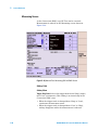
Measuring Screen 5-39
Measuring Talk Screen 5-43
Abort Screen 5-47
Sequence 2 Screen 5-51
Measurement Result Screen 5-53
viii
N9360A Multi UE Tester W-CDMA User Manual
Manual Test 5-59
Overview 5-59
RF Test in Manual Test 5-60
Stand-by Screen 5-61
Location Update Screen 5-67
MS Call Connection Response Screen
Connection Screen 5-72
Measuring Screen 5-80
CPICH RSCP Screen 5-81
Measurement Result Screen 5-82
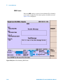
SMS Screen 5-90
HSDPA Screen 5-97
5-69
TX Analyzer 5-126
Overview 5-126
RF Test in TX Analyzer 5-126
Stand-by Screen 5-128
Measuring Screen 5-133
Measurement Result Screen 5-135
Signal Generator 5-140
Overview 5-140
Signal Generator Screen
5-140
Configuration 5-145
Overview 5-145
Configuration Screen 5-145
Configuration: Test Sequence Screen 5-150
Configuration: Test Condition Screen 5-156
Configuration: Test Condition (Loss) 5-165
Configuration: File Management 5-167
Saving Test Setup File 5-171
Recalling Test Setup File 5-176
Deleting Test Setup File 5-180
Replacing Test Setup Files (HDD is selected) 5-183
Replacing Test Setup Files (USB Memory Device is selected) 5-185
Undo Confirmation (HDD is selected) 5-186
Undo Confirmation (USB Memory Device is selected) 5-188
Configuration: Network Setting 5-190
6
Troubleshooting 6-1
Item To Be Checked 6-2
Error Information 6-4
Error Screen 6-4
N9360A Multi UE Tester W-CDMA User Manual
ix
Error Codes for Error Screens 6-5
7
Performance and Specifications 7-1
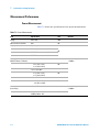
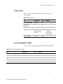
Measurement Performance 7-2
Power Measurement 7-2
Frequency Error 7-3
Error Vector Magnitude (EVM) 7-3
Origin Offset 7-4
Sensitivity/BER 7-4
ACLR DSB 5MHz (W07 Option) 7-4
ACLR DSB 10MHz (W07 Option) 7-5
OBW (W07 Option) 7-5
A
Appendix A Input Fields and Allowable Choices or Ranges A-1
B
Appendix B General Information on the W-CDMA (FDD) System
B-1
Frequency Bands B-2
TX-RX Frequency Separation B-2
Channel Number B-3
UARFCN B-3
UE Maximum Output Power B-4
List of Abbreviations B-5
C
Appendix C N9360A-A02 Antenna Coupler C-1
Introduction C-2
Specifications C-2
Operating the Antenna Coupler C-3
D
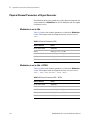
Appendix D Parameters of Physical Channels D-1
Physical Channel Parameters of Signal Generator D-2
Modulation is set to Idle D-2
Modulation is set to Idle + DPCH D-2
Modulation is set to Idle + DPCH + H-Set1 to H-Set5, CQI-1 to
CQI-30 D-3
Spreading code (non-HSDPA)
D-3
Spreading code (HSDPA) D-4
UL reference measurement channel (12.2 kbps) D-4
x
N9360A Multi UE Tester W-CDMA User Manual
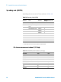
DL reference measurement channel (12.2 kbps)
DL reference channel (HSDPA) D-7
Fixed Reference Channel H-Set1
Fixed Reference Channel H-Set2
Fixed Reference Channel H-Set3
Fixed Reference Channel H-Set4
Fixed Reference Channel H-Set5
D-6
D-7
D-7
D-8
D-8
D-9
OCNS (non-HSDPA) D-10
OCNS (HSDPA) D-12
E
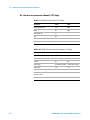
Appendix E Description of Radio Performance Test E-1
Open Loop Power E-2
Maximum Output Power
Error Vector Magnitude
E-4
E-5
Frequency Error E-7
Inner Loop Power
E-9
Reference Sensitivity E-13
ACLR DSB E-15
Minimum TX Power E-17
N9360A Multi UE Tester W-CDMA User Manual
xi
THIS PAGE IS INTENTIONALLY LEFT BLANK.
xii
N9360A Multi UE Tester W-CDMA User Manual
List of Figures
4
Operating Procedures 4-1
Figure 4-1
Figure 4-2
Figure 4-3
Figure 4-4
Figure 4-5
Figure 4-6
Figure 4-7
Figure 4-8
Figure 4-9
Figure 4-10
Figure 4-11
Figure 4-12
Figure 4-13
Figure 4-14
Figure 4-15
Figure 4-16
Figure 4-17
Figure 4-18
Figure 4-19
Figure 4-20
Figure 4-21
Figure 4-22
Figure 4-23
Figure 4-24
Figure 4-25
Figure 4-26
Screen
Figure 4-27
Figure 4-28
Figure 4-29
Figure 4-30
Figure 4-31
Update
Figure 4-32
Update
Figure 4-33
Figure 4-34
Figure 4-35
Figure 4-36
Figure 4-37
N9360A Multi UE Tester W-CDMA User Manual
Test Operation Flow 4-2
Typical Test Setup 4-3
Printer Connection 4-5
Connecting a USB-GPIB Converter 4-6
Screen Display Annotation 4-7
Softkeys for Storing Values 4-10
Memory Softkeys 4-11
Softkeys for Storing Values 4-12
Magnification Softkey 4-13
Top Menu 4-14
[Initial] Screen 4-15
[Configuration: Test Condition] Screen 4-16
[Initial] Screen 4-17
[Configuration: Test Condition (Loss)] Screen 4-22
[Configuration: Test Sequence] Screen 4-24
Downlink TX Power In Automatic Test 4-26
[Initial] Screen 4-27
[Configuration: Test Condition (Loss)] Screen 4-28
[Configuration: Test Sequence] Screen 4-29
[Configuration: Test Condition] Screen 4-30
[Auto Test: Stand-by] Screen 4-31
[Automatic Test: Stand-by] Value Screen 4-32
[Automatic Test: Measuring] MS Call Screen 4-33
[Automatic Test: Measuring] Talk Screen 4-34
[Automatic Test: Measuring] Sequence 2 Screen 4-35
[Automatic Test: Stand-by] Measurement Result
4-36
[Initial] Screen 4-37
[Configuration: Test Condition (Loss)] Screen 4-38
[Configuration: Test Condition] Screen 4-39
[Manual Test: Stand-by] Screen 4-40
[Manual Test: Measuring] Screen for Location
4-41
[Manual Test: Stand-by] Screen After Location
4-42
[Manual Test: Measuring] Connection Screen 4-44
[Manual Test: Stand-by] Screen After BS Release 4-45
[Initial] Screen 4-46
[Configuration: Test Condition (Loss)] Screen 4-47
[Configuration: Test Condition] Screen 4-48
xi
Figure 4-38
Figure 4-39
Figure 4-40
Figure 4-41
Figure 4-42
Figure 4-43
Figure 4-44
Figure 4-45
Figure 4-46
Figure 4-47
Figure 4-48
Figure 4-49
Figure 4-50
Figure 4-51
Figure 4-52
(HSDPA)
Figure 4-53
(HSDPA)
Figure 4-54
(HSDPA)
Figure 4-55
(HSDPA)
Figure 4-56
Figure 4-57
Figure 4-58
Figure 4-59
Figure 4-60
Figure 4-61
Screen
Figure 4-62
Figure 4-63
Figure 4-64
Figure 4-65
5
[Manual Test: Stand-by] Screen 4-49
[Manual Test: Measuring] Location Update Screen 4-50
[Manual Test: Measuring] Connection Screen 4-51
[Manual Test (GSM): Measuring] Screen 4-52
[Manual Test: Stand-by] Screen After BS Release 4-53
[Initial] Screen 4-54
[Configuration: Test Condition (Loss)] Screen 4-55
[Configuration: Test Condition] Screen 4-56
[Manual Test: Stand-by] Screen 4-57
[Manual Test: Measuring] Emergency Call Screen 4-58
[Initial] Screen 4-59
[Configuration: Test Condition (Loss)] Screen 4-60
[Configuration: Test Condition] Screen (HSDPA) 4-61
[Manual Test: Stand-by] Screen (HSDPA) 4-62
[Manual Test: Measuring] Location Update Screen
4-63
[Manual Test: Stand-by] After Location Update Screen
4-64
[Manual Test: Measuring] Connection Screen
4-65
[Manual Test: Stand-by] After BS Release Screen
4-66
[Initial] Screen 4-67
[Configuration: Test Condition (Loss)] Screen 4-68
[Configuration: Test Condition] Screen 4-69
[TX Analyzer: Stand-by] Screen 4-70
[TX Analyzer: Measuring] Screen 4-71
[TX Analyzer: Stand-by] Measurement Result
4-72
[Initial] Screen 4-73
[Configuration: Test Condition (Loss)] Screen 4-74
[Configuration: Test Condition] Screen 4-75
[Signal Generator] Screen 4-76
Screen Reference 5-1
Figure 5-1 Screen Structure Chart 5-2
Figure 5-2 Selectable Systems 5-3
Figure 5-3 [Top Menu] Screen 5-4
Figure 5-4 [Configuration] Screen (with Option E00/E01) 5-7
Figure 5-5 Part of [Configuration] screen (without Option E00 and
E02) 5-8
Figure 5-6 Part of [Configuration] screen (without Option E01) 5-9
Figure 5-7 [Firmware Update] Screen 5-14
xii
N9360A Multi UE Tester W-CDMA User Manual
Figure 5-8 [Update Flash] Screen 5-18
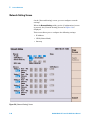
Figure 5-9 [Network Setting] Screen 5-20
Figure 5-10 [Initial] Screen 5-24
Figure 5-11 [Return to Menu] Screen 5-27
Figure 5-12 [PRESET Mode] Screen 5-28
Figure 5-13 [PRESET Mode] Screen (in W-CDMA System) 5-29
Figure 5-14 [Automatic Test : Stand-by] Simplified Screen 5-33
Figure 5-15 [Automatic Test : Stand-by] Detailed Screen 5-34
Figure 5-16 [Automatic Test: Stand-by] Value Screen 5-35
Figure 5-17 [Automatic Test: Measuring] Simplified Screen 5-40
Figure 5-18 [Automatic Test: Measuring] Detailed Screen 5-40
Figure 5-19 [Automatic Test: Measuring] Value Screen 5-41
Figure 5-20 [Automatic Test: Measuring] Talk Simplified Screen 5-43
Figure 5-21 [Automatic Test: Measuring] Talk Detailed Screen 5-44
Figure 5-22 [Automatic Test: Measuring] Talk Value Screen 5-44
Figure 5-23 [Automatic Test: Stand-by] Aborted Simplified
Screen 5-47
Figure 5-24 [Automatic Test: Measuring] Sequence 2 Simplified
Screen 5-51
Figure 5-25 [Automatic Test: Stand-by] Measurement Result Simplified
Screen 5-54
Figure 5-26 [Automatic Test: Stand-by] Measurement Result Detailed
Screen 5-54
Figure 5-27 [Automatic Test: Stand-by] Measurement Result Value
Screen 5-55
Figure 5-28 [Manual Test: Stand-by] Screen 5-61
Figure 5-29 [Manual Test: Measuring] Location Update Screen 5-67
Figure 5-30 [Manual Test: Measuring] MS Call Connection Response
Screen 5-69
Figure 5-31 [Manual Test: Measuring] MS Call Connection
Screen 5-72
Figure 5-32 [Manual Test: Measuring] BS Call AMR Connection
Screen 5-73
Figure 5-33 [Manual Test: Measuring] BS Call RMC Connection
Screen 5-74
Figure 5-34 [Manual Test: Measuring] BS Call RMC Screen 5-80
Figure 5-35 [Manual Test: Measuring] CPICH RSCP Screen 5-81
Figure 5-36 [Manual Test: Stand-by] BS Call RMC Measurement Result
Screen 5-83
Figure 5-37 [Manual Test: Stand-by] MS Call Measurement Result
Screen 5-83
Figure 5-38 [Manual Test: Stand-by] SMS Screen 5-90
Figure 5-39 [Manual Test: Measuring] Screen in SMS-MT or SMS-MO
Execution 5-96
Figure 5-40 [Manual Test: Stand-by] HSDPA Screen 5-98
N9360A Multi UE Tester W-CDMA User Manual
xiii
Figure 5-41 [Manual Test: Measuring] Location Update Screen 5-106
Figure 5-42 [Manual Test: Measuring] Connection Screen 5-109
Figure 5-43 [Manual Test: Measuring] Measurement Screen 5-115
Figure 5-44 [Measuring] CPICH RSCP Screen 5-119
Figure 5-45 [Stand-by] Measurement Result Screen 5-120
Figure 5-46 [TX Analyzer: Stand-by] Screen (Standard) 5-128
Figure 5-47 [TX Analyzer: Stand-by] Screen (with Option W07) 5-129
Figure 5-48 [TX Analyzer: Measuring] Screen (with Option
W07) 5-134
Figure 5-49 [TX Analyzer: Stand-by] Measurement Result Screen (with
Option W07) 5-136
Figure 5-50 [Signal Generator] Screen 5-141
Figure 5-51 [Configuration] Screen 5-146
Figure 5-52 Part of [Configuration] screen (without Option E00 and
E02) 5-147
Figure 5-53 Part of [Configuration] screen (without Option
E01) 5-147
Figure 5-54 [Configuration: Test Sequence] Screen 5-150
Figure 5-55 [Configuration: Test Condition] Screen (W-CDMA
Mode=W-CDMA) 5-156
Figure 5-56 [Configuration: Test Condition] Screen (W-CDMA
Mode=HSDPA) 5-157
Figure 5-57 [Configuration: Test Condition] Screen (with Option
W07) 5-158
Figure 5-58 [Configuration: Test Condition (Loss)] Screen 5-165
Figure 5-59 [Configuration: File Management] Screen 5-168
Figure 5-60 [Configuration: File Management] Save-1 Screen 5-171
Figure 5-61 [Configuration: File Management] Save-2 Screen 5-172
Figure 5-62 [Configuration: File Management] Save-3 Screen 5-173
Figure 5-63 [Configuration: File Management] Save-4 Screen 5-174
Figure 5-64 [Configuration: File Management] Overwrite
Screen 5-175
Figure 5-65 [Configuration: File Management] Recall-1 Screen 5-177
Figure 5-66 [Configuration: File Management] Recall-1 Screen 5-177
Figure 5-67 [Configuration File Management] Recall-3 Screen 5-179
Figure 5-68 [Configuration File Management] Delete-1 Screen 5-180
Figure 5-69 [Configuration File Management] Delete-2 Screen 5-181
Figure 5-70 [Configuration File Management] Delete-3 Screen 5-182
Figure 5-71 File Replace Screen (HDD is selected) 5-183
Figure 5-72 File Replace Screen (USB memory device is
selected) 5-185
Figure 5-73 Undo Screen (HDD is selected) 5-187
Figure 5-74 Undo Screen (USB memory device is selected) 5-188
Figure 5-75 [Configuration: Network Setting] Screen 5-190
xiv
N9360A Multi UE Tester W-CDMA User Manual
6
Troubleshooting 6-1
Figure 6-1
C
Appendix C N9360A-A02 Antenna Coupler C-1
Figure C-1
Figure C-2
E
An Example of [Error] Screens 6-4
Agilent N9360A-A02 Antenna Coupler C-3
Operating the Antenna Coupler C-4
Appendix E Description of Radio Performance Test E-1
Figure E-1
Figure E-2
Figure E-3
Figure E-4
Figure E-5
Figure E-6
Figure E-7
Figure E-8
Figure E-9
Figure E-10
Figure E-11
Figure E-12
Figure E-13
Figure E-14
Figure E-15
Figure E-16
Figure E-17
N9360A Multi UE Tester W-CDMA User Manual
Open Loop Power Measurement Image E-2
Open Loop Power Measurement Flow E-3
Maximum Output Power Measurement Image E-4
Maximum Output Power Measurement Flow E-4
Error Vector Magnitude Measurement Image E-5
Error Vector Magnitude Measurement Flow E-6
Frequency Error Measurement Image E-7
Frequency Error Measurement Flow E-8
Inner Loop Power Measurement Image E-9
Inner Loop Power Pattern E-10
Inner Loop Power Measurement Flow E-12
Reference Sensitivity Measurement Image E-13
Reference Sensitivity Measurement Flow E-14
Measurement Image of ACLR DSB 5MHz E-15
Measurement Image of ACLR DSB 10MHz E-16
Minimum TX Power Measurement Image E-17
Minimum TX Power Measurement Flow E-18
xv
THIS PAGE IS INTENTIONALLY LEFT BLANK.
xvi
N9360A Multi UE Tester W-CDMA User Manual
List of Tables
1
3
4
Legal Information 1-1
Table 1-1
Agilent Call Centers and Regional Headquarters 1-3
Table 3-1
Table 3-2
Table 3-3
Table 3-4
W-CDMA Functions 3-2
Configuration 3-5
Options 3-6
Accessories 3-7
Overview 3-1
Operating Procedures 4-1
Table 4-1
5
Description of Screen Display Annotation 4-8
Screen Reference 5-1
Table 5-1 [Configuration] Screen Input Field 5-9
Table 5-2 [Network Setting] Screen Input Field 5-21
Table 5-3 [Initial] Screen Input Field 5-26
Table 5-4 Automatic Test Measurement Items 5-31
Table 5-5 [Automatic Test: Stand-by] Screen Selections 5-33
Table 5-6 [Automated Test: Stand-by] Screen Input Fields 5-36
Table 5-7 [Auto Test: Stand-by] Screen With Mobile Phone
Information 5-38
Table 5-8 [Auto Test: Measuring] Screen Selections 5-39
Table 5-9 Mobile Phone Information in [Auto Test: Measuring]
Screen 5-42
Table 5-10 [Auto Test: Measuring] Talk Screen Selections 5-43
Table 5-11 Mobile Phone Information in [Auto Test: Measuring Talk]
Screen 5-46
Table 5-12 [Auto Test: Abort] Screen Input Parameters 5-48
Table 5-13 [Automatic Test] Aborted Screen Mobile Phone
Information 5-50
Table 5-14 [Automatic Test] Sequence 2 Screen Mobile Phone
Information 5-52
Table 5-15 [Auto Test: Stand-by] Measurement Result Screen
Selections 5-53
Table 5-16 [Auto Test: Stand-by] Measurement Results Screen Input
Field 5-56
Table 5-17 Description of Manual Test Measurement Items 5-60
Table 5-18 [Manual Test: Stand-by] Screen Input Field 5-63
N9360A Multi UE Tester W-CDMA User Manual
xiii
Table 5-19 [Manual Test: Stand-by] Screen Mobile Phone
Information 5-65
Table 5-20 MS Call Connection Response Screen Mobile Phone
Information 5-70
Table 5-21 [Manual Test] Connection Screen Input Field 5-76
Table 5-22 [Manual Test] Connection Screen Mobile Phone
Information 5-78
Table 5-23 [Manual Test] Measurement Result Screen Input
Field 5-86
Table 5-24 [Manual Test] Measurement Result Screen Mobile Phone
Information 5-88
Table 5-25 [Manual Test] SMS Screen Input Field 5-91
Table 5-26 [Manual Test] SMS Information 5-93
Table 5-27 Manual Test Measurement Item 5-97
Table 5-28 [Manual Test: Stand-by] Screen Input Field 5-100
Table 5-29 Ec/Ior Setting Combination 5-103
Table 5-30 [Manual Test: Stand-by] Screen Mobile Phone
Information 5-104
Table 5-31 [Manual Test: Location Update] Screen Mobile Phone
Information 5-107
Table 5-32 [Manual Test] Connection Screen Input Field 5-110
Table 5-33 [Manual Test] Connection Screen Mobile Phone
Information 5-113
Table 5-34 Measurement items of HSDPA Manual Test 5-116
Table 5-35 [Manual Test] Connection Screen Mobile Phone
Information 5-118
Table 5-36 [Manual Test] Measurement Result Screen Input
Field 5-122
Table 5-37 [Manual Test] Mobile Phone Information 5-125
Table 5-38 TX Analyzer Measurement Item (Standard) 5-126
Table 5-39 TX Analyzer Measurement Item (with Option W07) 5-127
Table 5-40 Example of ACLR DSB Measurement Result 5-127
Table 5-41 [TX Analyzer: Stand-by] Screen Input Field 5-130
Table 5-42 [TX Analyzer: Measurement] Results Screen Input Field
Descriptions 5-137
Table 5-43 [Signal Generator] Screen Input Field 5-142
Table 5-44 [Configuration] Screen Input Field 5-148
Table 5-45 [Configuration] Screen Information 5-149
Table 5-46 [Configuration: Test Sequence] Screen Input Field 5-153
Table 5-47 [Configuration: Test Condition] Screen Input Field 5-158
Table 5-48 [Configuration: Test Condition] Screen Test Limits 5-160
Table 5-49 [Configuration: Test Condition] Screen Input Field 5-162
Table 5-50 [Configuration: Test Condition] Screen Test Limits 5-164
Table 5-51 [Configuration: Test Condition (Loss)] Screen Input
Field 5-166
xiv
N9360A Multi UE Tester W-CDMA User Manual
Table 5-52 [Configuration: Test Condition (Loss)] Screen Input
Field 5-166
Table 5-53 Error Message in File Management 5-170
6
Troubleshooting 6-1
Table 6-1
Table 6-2
Table 6-3
7
Performance and Specifications 7-1
Table 7-1
Table 7-2
Table 7-3
Table 7-4
Table 7-5
Table 7-6
Table 7-7
Table 7-8
A
Input Fields and Allowable Choices or Ranges
Appendix B General Information on the W-CDMA (FDD) System
Table B-1
Table B-2
Table B-3
Table B-4
Table B-5
Table B-6
D
Power Measurement 7-2
Frequency Error 7-3
Error Vector Magnitude (EVM) 7-3
Origin Offset 7-4
Sensitivity/BER 7-4
ACLR DSB 5MHz 7-4
ACLR DSB 10MHz 7-5
OBW 7-5
Appendix A Input Fields and Allowable Choices or Ranges A-1
Table A-1
B
Item To Be Checked 6-2
Alarm Notification Error Code 6-5
UI Timer Error Code 6-6
A-2
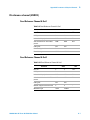
B-1
Frequency Bands B-2
TX-RX Frequency Separation B-2
UARFCN Definition B-3
UARFCN Definition (Band II Additional Channels) B-3
UARFCN B-3
UE Maximum Output Power B-4
Appendix D Parameters of Physical Channels D-1
Table D-1
Table D-2
Table D-3
Table D-4
Table D-5
Table D-6
N9360A Multi UE Tester W-CDMA User Manual
Channel Parameter (IDLE) D-2
Channel Parameter (IDLE + DPCH) D-2
Spreading Code (non-HSDPA) D-3
Spreading Code (HSDPA) D-4
UL RMC Physical Parameters (12.2 kbps) D-4
UL RMC Transport Channel Parameters (12.2 kbps) D-5
xv
Table D-7 DL RMC Physical Channel (12.2 kbps) D-6
Table D-8 DL RMC Transport Channel Parameters (12.2 kbps) D-6
Table D-9 Fixed Reference Channel H-Set1 D-7
Table D-10 Fixed Reference Channel H-Set2 D-7
Table D-11 Fixed Reference Channel H-Set3 D-8
Table D-12 Fixed Reference Channel H-Set4 D-8
Table D-13 Fixed Reference Channel H-Set5 D-9
Table D-14 Electric Ratio of Downlink Physical Channel D-10
Table D-15 DPCH Channelization Code and Relative Level Setting for
OCNS Signal D-11
Table D-16 Code Power Ratio of Downlink Physical Channel D-12
Table D-17 OCNS Definition for HSDPA Receiver Testing D-14
E
Appendix E Description of Radio Performance Test E-1
Table E-18
xvi
Measurement Result of Inner Loop Power E-11
N9360A Multi UE Tester W-CDMA User Manual
1
Legal Information
Legal Information 1-2
Warranty 1-2
Technology Licenses 1-2
Restricted Rights Legend 1-2
Service And Support 1-3
Agilent On The Web 1-3
Agilent By Phone 1-3
Manufacturing Address 1-3
Agilent Technologies
1-1
1
Legal Information
Legal Information
Warranty
The material contained in this document is provided “as is,” and
is subject to being changed, without notice, in future editions.
Further, to the maximum extent permitted by applicable law,
Agilent disclaims all warranties, either express or implied, with
regard to this manual and any information contained herein,
including but not limited to the implied warranties of
merchantability and fitness for a particular purpose. Agilent
shall not be liable for errors or for incidental or consequential
damages in connection with the furnishing, use, or performance
of this document or of any information contained herein.
Should Agilent and the user have a separate written agreement
with warranty terms covering the material in this document
that conflict with these terms, the warranty terms in the
separate agreement shall control.
Technology Licenses
The hardware and/or software described in this document are
furnished under a license and may be used or copied only in
accordance with the terms of such license.
Restricted Rights Legend
If software is for use in the performance of a U.S. Government
prime contract or subcontract, Software is delivered and
licensed as “Commercial computer software” as defined in
DFAR 252.227-7014 (June 1995), or as a “commercial item” as
defined in FAR 2.101(a) or as “Restricted computer software” as
defined in FAR 52.227-19 (June 1987) or any equivalent agency
regulation or contract clause. Use, duplication or disclosure of
Software is subject to Agilent Technologies’ standard
commercial license terms, and non-DOD Departments and
Agencies of the U.S. Government will receive no greater than
Restricted Rights as defined in FAR 52.227-19(c)(1-2)(June
1987). U.S. Government users will receive no greater than
Limited Rights as defined in FAR 52.227-14 (June 1987) or
DFAR 252.227-7015 (b)(2)(November 1995), as applicable in any
technical data.
1-2
N9360A Multi UE Tester W-CDMA User Manual
Legal Information
1
Service And Support
Any adjustment, maintenance, or repair of this product must be
performed by qualified personnel. Contact your customer
engineer through your local Agilent Technologies Service
Center.
Agilent On The Web
You can find information about technical and professional
services, product support, and equipment repair and service on
the Web: http://www.agilent.com/
Double-click the link to Test & Measurement. Select your country
from the drop-down menus. The Web page that appears next has
contact information specific for your country
Agilent By Phone
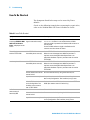
If you do not have access to the Internet, call one of the
numbers in Table 1-1.
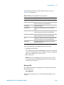
Table 1-1 Agilent Call Centers and Regional Headquarters
United States and Canada:
Test and Measurement Call Center
(800) 452 4844 (toll-free in US)
Europe:
(41 22) 780 8111
Japan:
Measurement Assistance Center
(81) 0426 56 7832
Latin America:
305 269 7548
Asia-Pacific:
(85 22) 599 7777
Manufacturing Address
Agilent Technologies Microwave Products (Malaysia) Sdn. Bhd.
Bayan Lepas Free Industrial Zone,
11900 Penang,
Malaysia.
N9360A Multi UE Tester W-CDMA User Manual
1-3
1
Legal Information
THIS PAGE IS INTENTIONALLY LEFT BLANK.
1-4
N9360A Multi UE Tester W-CDMA User Manual
2
Caution and Safety Requirements
Safety Summary 2-2
Safety Notices 2-2
Warning Label 2-2
General 2-3
When Operating The Tester 2-3
Agilent Technologies
2-1
2
Caution and Safety Requirements
Safety Information
Safety Summary
The following general safety precautions must be observed
during all phases of operation of this instrument. Failure to
comply with these precautions or with specific warnings
elsewhere in this manual violates safety standards of design,
manufacture, and intended use of the instrument. Agilent
Technologies, Inc. assumes no liability for the customer's failure
to comply with these requirements.
Safety Notices
CAUTION
WA R N I N G
A CAUTION notice denotes a hazard. It calls attention to an
operating procedure, practice, or the like, that, if not correctly
performed or adhered to, could result in damage to the product or
loss of important data. Do not proceed beyond a CAUTION notice
until the indicated conditions are fully understood and met.
A WARNING notice denotes a hazard. It calls attention to an
operating procedure, practice, or the like that, if not correctly
performed or adhered to, could result in personal injury or death.
Do not proceed beyond a WARNING notice until the indicated
conditions are fully understood and met.
Warning Label
A warning label is stuck on the front panel of the Tester.
Do not remove, damage or modify the warning label.
2-2
N9360A Multi UE Tester W-CDMA User Manual
Caution and Safety Requirements
2
General
WA R N I N G
WA R N I N G
The protection provided by the N9360A Tester may be impaired if
the tester is used in a manner not specified by Agilent or the
instructions on the display are not followed.
DO NOT INSTRUMENT COVERS. Operating personnel must not
remove any instrument covers. Component replacement and
internal adjustments must be made only by qualified service
personnel. Products that appear damaged or defective should be
made inoperative and secured against unintended operation until
they can be repaired by a qualified service personnel.
When Operating The Tester
CAUTION
CAUTION
Make sure that the input signal level does not exceed the maximum level
allowed. Tester failure may result otherwise.
Do not turn off the Line switch on the rear panel of the Tester while the
LINE LED on the front panel of the Tester is lit in green. Otherwise, Tester
failure may occur.
N9360A Multi UE Tester W-CDMA User Manual
2-3
2
Caution and Safety Requirements
THIS PAGE IS INTENTIONALLY LEFT BLANK.
2-4
N9360A Multi UE Tester W-CDMA User Manual
3
Overview
Functions 3-2
Features 3-4
Configuration 3-5
Options 3-6
Accessories 3-7
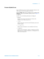
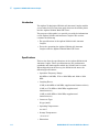
This chapter outlines the feature of the N9360A W-CDMA
Option. For functions of the GSM Option, refer to the N9360A
GSM Option User Manual, and for functions of the cdma2000
Option, refer to the N9360A cdma2000 Option User Manual.
Agilent Technologies
3-1
3
Overview
W-CDMA Option provides the software for the N9360A Multi UE
Tester to support signaling tests and RF performance tests in
inspection processes for production, service, repair and
maintenance.
This option supports Band 1 and Band 6. Agilent has also
planned to provide options for Band 2 to Band 5.
The W-CDMA option allows the tester to carry out radio
performance tests with call processes. In addition, it
implements TX Analyzer function to execute RF radio
performance tests without call processes and Signal Generator
function used for adjusting radio parts.
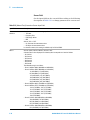
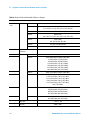
Functions
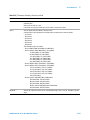
The functions available with the W-CDMA options are listed in
Table 3-1.
Table 3-1 W-CDMA Functions
Function
W-CDMA (Option)
Description
Band: 1, 6
Signalling Test
W-CDMA
Location update
MS Call
Talk
MS Release
BS Call (AMR)
Talk
BS Release
BS Call (RMC)
BS Call (HSDPA) (Option W06)
RF Test
BS Release
SMS
SMS MT, SMS MO
RF Test
Open Loop Power Control
(Open Loop TX Power)
3-2
N9360A Multi UE Tester W-CDMA User Manual
Overview
3
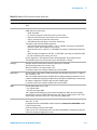
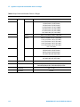
Table 3-1 W-CDMA Functions (continued)
Function
Description
W-CDMA (Option)
Inner Loop Power Control
ILP (Down Min)
ILP (Down Max)
ILP (Up Min)
ILP (Up Max)
ILP (10 slots Down)
ILP (10 slots Up)
Maximum Output Power
(MAX TX Power)
Frequency Error
Error Vector Magnitude (EVM)
Origin Offset
Reference Sensitivity Level
(Sensitivity/BER)
ACLR DSB 5MHz
ACLR DSB 10MHz
OBW
TX Analyzer
Signal Generator
Remote Control
N9360A Multi UE Tester W-CDMA User Manual
Ethernet
GP-IB (Option E00 or Option E02)
Serial (Option E01)
3-3
3
Overview
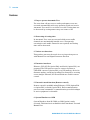
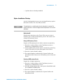
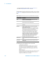
Features
1 Easy-to-operate Automatic Test
The tests from call processes to radio performance tests are
executed automatically with easy operation. Each test item in
Automatic Test can be set to either On or Off. Testing time can
be shortened by setting unnecessary test items to Off.
2 Shortening of testing time
In Automatic Test, tests are executed while preset traffic
channels are automatically handed over. Consequently,
retesting for each traffic channel is not required, and testing
time can be shortened.
3 Various test functions
This product can meet the needs in every inspection process
with Manual Test and Signal Generator function.
4 Extensive interfaces
Ethernet, USB, GP-IB (Option E00) and Serial (Option E01) are
prepared. The USB ports are used to connect a printer, a
USB-GPIB converter (Option E02) or a USB memory device for
firmware update, saving and recalling Test Setup files, or saving
screen images. Ethernet, GP-IB and Serial are used for remote
control.
5 External control function (Remote control)
Remote control is available using Ethernet, GP-IB (Option E00
or Option E02) or Serial (Option E01). Each communication
port uses same commands. A communication port which adapts
to user's equipment is selectable.
6 System Handover to GSM
System Handover from W-CDMA to GSM (Option) can be
executed. This function is available for both Automatic Test and
Manual Test.
3-4
N9360A Multi UE Tester W-CDMA User Manual
Overview
3
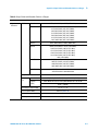
Configuration
The W-CDMA software comes ready installed in the tester when
the user purchases the W-CDMA option.
This manual also accompanies the W-CDMA option.
Table 3-2 Configuration
Item name
Type
Quantity
Remarks
W-CDMA Standard
W00
1
Installed on the Tester
User Manual
N9360A-90701
1
Programming Manual
N9360A-90703
1
Quick Reference
N9360A-90002
1
Installation Guide
N9360A-90001
1
Certificate of Calibration
—
1
GP-IB Port
E00
IEEE, 24 pin Connector (Amphenol)
GP-IB Port
Serial Port
E01
D-sub 9 pin male Connector
Serial Port
HSDPA Option
W06
HSDPA function
HSDPA Option
ACLR/OBW Measurement Option
W07
N9360A Multi UE Tester W-CDMA User Manual
Containes in the CD-R
(Type: N9360-90003)
3-5
3
Overview
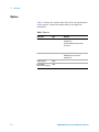
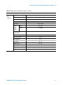
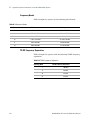
Options
Table 3-3 shows the options of the Tester. For the specification
of the options, contact the Agilent Sales or an approved
distributor.
Table 3-3 Options
3-6
Item Name
Type
Remarks
GP-IB
E00
IEEE488, 24 pin Connector
(Amphenol)
Serial PortE01D-sub 9 pin male
Connector
USB-GPIB Converter
E02
Use USB interface.
IEEE488, 24 pin Connector
(Amphenol)
HSDPA Option
W06
ACLR/OBW
Measurement Option
W07
N9360A Multi UE Tester W-CDMA User Manual
Overview
3
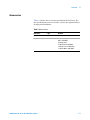
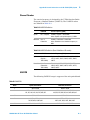
Accessories
Table 3-4 shows the accessories provided with the Tester. For
the specification of the accessories, contact the Agilent Sales or
an approved distributor.
Table 3-4 Accessories
Item Name
Type
TEST USIM card
—
Antenna coupler
N9360A-A02
N9360A Multi UE Tester W-CDMA User Manual
Remarks
Frequency Range:
824 to 1990 MHz
Coupling Factor:
15 dB (at 824 to 960 MHz)
13 dB (at 1710 to 1880 MHz)
11 dB (at1880 to 1990 MHz)
3-7
3
Overview
THIS PAGE IS INTENTIONALLY LEFT BLANK.
3-8
N9360A Multi UE Tester W-CDMA User Manual
4
Operating Procedures
Test Flow 4-2
Test Preparation 4-3
System Requirements 4-3
Installing The Test USIM 4-4
Connections 4-4
Test Procedure 4-7
Activating the Tester 4-7
General Operation 4-7
Selecting Items and Changing Parameters 4-9
System Selection 4-14
Function Mode Selection On The [Initial] Screen 4-17
RF IN/OUT Loss Correction 4-19
Testing Mobile Phone Using Automatic Test 4-25
Testing Mobile Phone Using Manual Test 4-37
Handover 4-46
Emergency Call 4-54
Testing a Mobile Phone by Manual Test (HSDPA Mode) 4-59
Testing a Mobile Phone by TX Analyzer 4-67
Testing a Mobile Phone by Signal Generator 4-73
Ending A Test 4-77
Disconnecting the Mobile Phone 4-77
Turning off the Tester at the End of Test 4-77
This chapter describes the preparations required and the
operating procedures before starting the test of a W-CDMA
Mobile Phone. For the testing method of a GSM Mobile Phone,
refer to the N9360A GSM Option User Manual, and for the
testing method of a cdma2000 Mobile Phone, refer to the
N9360A cdma2000 Option User Manual.
Agilent Technologies
4-1
4
Operating Procedures
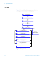
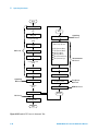
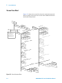
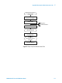
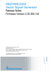
Test Flow
Figure 4-1 shows the flow of the test operation to check the
mobile phone with the N9360A W-CDMA option.
2.2.1
System Requirement
2.2.2
Installing the TEST USIM
2.2.3
Connection
2.3.1
Activating the Tester
2.3.3
Selection of System
GSM
W-CDMA
2.3.4
Selection of Function Mode on
the Initial Screen
2.3.6
Testing a Mobile Phone by
Automatic Test
2.3.7
Testing a Mobile Phone by
Manual Test
2.3.10
Testing a Mobile Phone by
TX Analyzer
2.3.11
Testing a Mobile Phone by
Signal Generator
2.4
GSM System
Refer to the N9360A
GSM User Manual
Ending a Test
Figure 4-1 Test Operation Flow
4-2
N9360A Multi UE Tester W-CDMA User Manual
Operating Procedures
4
Test Preparation
CAUTION
Make sure that the input signal level does not exceed the maximum
level allowed. Otherwise, Tester failure may occur.
The following procedures are require before proceeding with
any test:
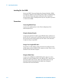
System Requirements
• The following equipment are required to setup the test
system:
• The Agilent N9360A Multi UE Tester.
• An RF cable, RF antenna coupler (type N9360A-A02) or
shield case (part number type N9360A-S01) to connect RF
signals to the mobile phone under test.
• A printer and a printer cable if required.
Figure 4-2 Typical Test Setup
N9360A Multi UE Tester W-CDMA User Manual
4-3
4
Operating Procedures
Installing The Test USIM
Insert the TEST Universal Subscriber Identity Module (USIM)
provided by Agilent in the mobile phone before performing any
test. This is because the Tester will not be able to perform
measurements with a USIM provided by the cell phone operator
or other test USIMs.
Connections
Connecting Mobile Phone
Connect the mobile phone to the Tester using any of the
following methods.
Using the Antenna Coupler
Connect the Antenna Coupler (type N9360A-A02) connector to
the RF IN/OUT connector on the front panel of the Tester. Insert
the antenna of the mobile phone into the hole of the Antenna
Coupler as deep as possible.
Using a User-Supplied RF Cable
If you have a cable which connects between the RF port of the
mobile phone and the RF IN/OUT connector of the Tester, use it
instead of the Antenna Coupler.
Using the Shield Case
Connect the ANTENNA COUPLER IN/OUT connector of the
shield case (type N9360A-S01) to the RF IN/OUT connector on
the front panel of the Tester. Place the mobile phone on the
antenna coupler board inside the shield case using the
horizontal and vertical holders.
4-4
N9360A Multi UE Tester W-CDMA User Manual
Operating Procedures
4
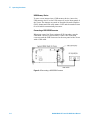
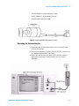
Connecting a Printer
Agilent recommends the EPSON PM-G800 for use with the
N9360A tester.
To print screen hard copies, connect the printer to the Tester as
shown in Figure 4-3 using an appropriate interface cable
between the USB Connector on the rear panel of the Tester and
the USB interface connector of the printer. Refer to the printer
manual for the various printer operating mode.
Figure 4-3 Printer Connection
N9360A Multi UE Tester W-CDMA User Manual
4-5
4
Operating Procedures
USB Memory Device
To save screen images into a USB memory device, insert the
USB memory device to the USB connector on the front panel of
the Tester. The images are saved in Portable Network Graphics
(PNG) format and with a file name: COPY and the number from
00 to 99 which automatically increases.
Connecting a USB-GPIB Converter
When you control the Tester using a GP-IB interface, use the
USB-GPIB converter (Option E02). Connect the USB-GPIB
converter and the USB connector on the rear panel of the Tester
with a USB cable.
Figure 4-4 Connecting a USB-GPIB Converter
4-6
N9360A Multi UE Tester W-CDMA User Manual
Operating Procedures
4
Test Procedure
Activating the Tester
To activate the Tester, turn on the LINE switch on the rear
panel of the Tester and press the LINE switch on the front
panel.
NOTE
Provide warm up of 30 minutes or more to ensure correct measurement.
General Operation
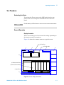
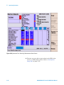
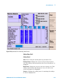
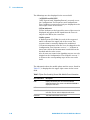
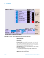
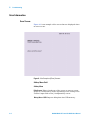
Display Annotation
There are several types of screen used in testing, depending on
the functions and test situations.
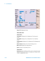
Figure 4-5 shows the common areas on a typical screen.
a) Test Flow
1
Automatic
Test
2
b) Test Results
3
Stand-by
2037/12/31 23:59
4
5
c) Measurement Item
d) Measurement Result
e) Input Field
6
Press [Start] to begin a test.
Figure 4-5 Screen Display Annotation
N9360A Multi UE Tester W-CDMA User Manual
4-7
4
Operating Procedures
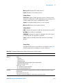
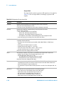
Table 4-1 Description of Screen Display Annotation
4-8
No. Name
Description
1
Function Mode
Field
The current function mode, for example, Automatic
Test, Manual Test, TX Analyzer and Configuration, is
displayed in this field.
2
Status Display
Field
The current operation status, for example, Stand-by,
Measuring, Test Sequence and Test Condition, is
displayed in this field.
3
Date/Time Field
The current date and time are displayed in this field.
4
Softkey Menu
Field
The softkey labels are displayed in this field. Each
label defines the function of the corresponding
softkey immediately next to the right of the label.
5
Screen Field
A variety of information is displayed in this field
depending on the operation status. For example, in
Automatic Test, the following information is displayed
in this field.
a) Test flow: Location Update, MS Call, BS Call, etc.
b) Test results: P (pass) or F (fail).
c) Measurement items: Peak TX Power, Frequency
Error, etc.
d) Measurement results: Pass/Fail or values.
e) Input field: Highlighted fields.
6
Message Field
Operation message for test flow steps are displayed in
this field. In this field, the word surrounded by bracket
"[]" denotes the softkey.
N9360A Multi UE Tester W-CDMA User Manual
Operating Procedures
4
Selecting Items and Changing Parameters
Depending on the function modes, the Tester has a number of
input fields to be specified or defined to configure a test flow,
test sequence and test condition. The allowable ranges for those
input fields depending on the radio systems are explained in the
following parts of this guide. Summarized information is
described in “Appendix A Input Fields and Allowable Choices
or Ranges" on page A-1.
Selecting an Input Field and Specifying a Value
All input fields to be specified are highlighted and the circular
cursor is shown next to an input field.
To specify a value, select an input field and then specify a value
to the input field by the following procedure:
1 Rotate the CURSOR CONTROL knob clockwise to move
the cursor downward or right, or rotate it
counterclockwise to move it upward or left, and place it
next to the input field you want to change.
2 Press the CURSOR CONTROL knob once. The highlighted
input field changes to normal display and circular cursor
changes to a triangular one.
3 Rotate the CURSOR CONTROL knob clockwise or
counterclockwise to find the values defined for it.
4 Press the CURSOR CONTROL knob to enter the desired
value in the input field. The input field is highlighted
again and the triangular cursor returns to the circular
one.
N9360A Multi UE Tester W-CDMA User Manual
4-9
4
Operating Procedures
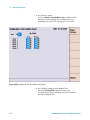
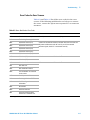
Storing Numeric Values
For numeric input fields such as channel numbers and
relevancies of amplitude, the user can store up to four numeric
values into the memory softkey menus with the following
procedure:
1 Move the cursor to one of the numeric input fields of
channels or relevancies of amplitude.
2 Press the CURSOR CONTROL knob to select the field. The
softkey menu as Figure 4-6 is displayed on the screen. The
memory softkeys show the values previously stored in the
memories if any.
Figure 4-6 Softkeys for Storing Values
3 Set a numeric value in the input field with the CURSOR
CONTROL knob.
4-10
N9360A Multi UE Tester W-CDMA User Manual
Operating Procedures
4
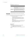
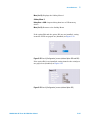
4 Press the Store Value to Memory>> softkey. The softkey
menu including Memory 1, Memory 2, Memory 3 and Memory
4 softkeys as Figure 4-7 is displayed.
Figure 4-7 Memory Softkeys
5 Press any of the memory softkeys from Memory 1 to
Memory 4 where you desire to store that value.
6 The memory softkey menu returns to the state in step 2
showing the value newly stored.
7 Press the CURSOR CONTROL knob to set the value into
the field. The softkey menu returns to that of step 1.
8 Repeat the procedure from step 1 to step 7, if required.
N9360A Multi UE Tester W-CDMA User Manual
4-11
4
Operating Procedures
Recalling Numeric Values
1 Move the cursor to one of the numeric input fields of
channels or relevancies of amplitude.
2 Press the CURSOR CONTROL knob to select the field. The
softkey menu as Figure 4-8 is displayed on the screen. The
four memory softkeys show the values previously stored
in the memories if any.
Figure 4-8 Softkeys for Storing Values
3 Press Memory 1, Memory 2, Memory 3 or Memory 4 softkey to
enter the stored value to the field.
4 The value is entered to the field.
4-12
N9360A Multi UE Tester W-CDMA User Manual
Operating Procedures
4
5 Press the CURSOR CONTROL knob to return the softkey
menu to that of Step 1.
If the value storage softkey where any value is not
registered is pressed at the input field of RFCH 2, 3, 4, 5 or
6 on the [Auto Test] screen or the [Configuration: Test
Sequence] screen, "----" is displayed at the input field. For
other input fields, the value displayed in the input field
does not change even if the value storage softkey without
registered value is pressed there.
Changing Magnification Softkey
Press the CURSOR CONTROL knob to select a numeric input
field, such as channels and relevancies of amplitude. A changing
magnification softkey as Figure 4-9 is displayed with memory
softkeys. A selected magnification is underlined.
Figure 4-9 Magnification Softkey
Pressing this softkey changes the multiplier from 1 to 1000.
Rotating the CURSOR CONTROL knob clockwise changes the
numeric value in the input field by an increment, and
counterclockwise changes the value by a decrement. The
following multiplies are variable.
• x1: Increment/decrement by 1,
• x10: Increment/decrement by 10,
• x100: Increment/decrement by 100,
• x1000: Increment/decrement by 1000.
N9360A Multi UE Tester W-CDMA User Manual
4-13
4
Operating Procedures
System Selection
On this screen, select a system from GSM, W-CDMA or
cdma2000.
NOTE
This guide describes only the W-CDMA system. For GSM system and
cdma2000 system, please refer to the GSM User Manual and the
cdma2000 User Manual.
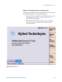
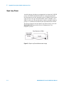
1 Turn on the Tester. The [Top Menu] screen is displayed as
Figure 4-10.
Figure 4-10 Top Menu
4-14
N9360A Multi UE Tester W-CDMA User Manual
Operating Procedures
4
2 Press the W-CDMA softkey to select the W-CDMA system.
The [Initial] screen for W-CDMA is displayed after the
Tester completes its initialization and self-test routine.
NOTE
When the AutoBoot function is set to FUNC GSM, FUNC W-CDMA or
FUNC CDMA2000, the Tester automatically selects the GSM, W-CDMA or
cdma2000 system mode if no softkey is pressed within the specified time
(10 to 60 seconds). When the Tester is shipped, the AutoBoot function is
set to None. Refer to the “AutoBoot" on page 5-10 for details.
Figure 4-11 [Initial] Screen
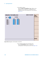
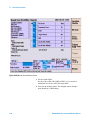
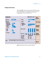
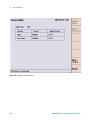
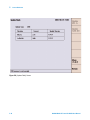
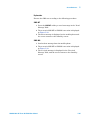
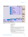
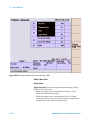
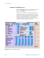
3 Press the Config softkey on the [Initial] screen, and then
press the Test Condition softkey on the [Configuration]
screen. The [Configuration: Test Condition] screen as
shown in Figure 4-12.
N9360A Multi UE Tester W-CDMA User Manual
4-15
4
Operating Procedures
Figure 4-12 [Configuration: Test Condition] Screen
4 Set the “3GPP System” and “Signaling Pattern” input
fields.
5 Press the Return softkey twice to return to the [Initial]
screen.
4-16
N9360A Multi UE Tester W-CDMA User Manual
Operating Procedures
4
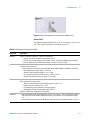
Function Mode Selection On The [Initial] Screen
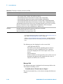
The tester executes its initialization and self-test routine after
completion of system setting. The [Initial] screen is then
displayed. Press one of the softkeys on the left side of the screen
to select a function mode.
Figure 4-13 [Initial] Screen
N9360A Multi UE Tester W-CDMA User Manual
4-17
4
Operating Procedures
Softkey Menu 1
• Automatic Test: Starts the Automatic Test. Refer to
“Testing Mobile Phone Using Automatic Test" on
page 4-25.
• Manual Test: Starts the Manual Test. Refer to “Testing
Mobile Phone Using Manual Test" on page 4-37 for
W-CDMA mode. Refer to “Testing a Mobile Phone by
Manual Test (HSDPA Mode)" on page 4-59 for HSDPA
mode.
• TX Analyzer: Starts the TX Analyzer test. Refer to
“Testing a Mobile Phone by TX Analyzer" on page 4-67.
• Signal Generator: Starts a test with the Signal Generator.
Refer to “Testing a Mobile Phone by Signal Generator" on
page 4-73.
• More (1 of 2): Displays the softkey menu 2.
• Config: Goes to the [Configuration] screen to set
parameters. Refer to “Configuration Screen" on
page 5-145.
Softkey Menu 2
• Print Screen: Prints the hard-copy of the screen or stores
the screen image into the USB memory, according to the
"Printer" setting on the [Configuration] screen.
• Return to Menu: This softkey is not for selecting a
function mode. The screen returns to the [Top Menu]
screen when this softkey is pressed. Refer to “Return to
Menu Screen" on page 5-27 for detail.
• More (2 of 2): Returns to the Softkey Menu 1.
4-18
N9360A Multi UE Tester W-CDMA User Manual
Operating Procedures
4
RF IN/OUT Loss Correction
Actual Input/Output Level and Correction
1 Actual Output Level and Correction in Automatic Test
(Except RF test), Manual Test and Signal Generator
The output signal of the tester is corrected for cable loss,
coupling loss, etc. by properly setting the parameters
described below
The actual output level (for downlink signal) at the RF
IN/OUT connector in the Automatic Test mode (except RF
test), the Manual Test mode and Signal Generator mode is
calculated by the following equation.
OutputLevel = BsLevel + LossRfOut
Where:
OutputLevel
The actual output level at the RF IN/OUT
connector.
BsLevel
The setting value at the "BS Level" field
on the [Configuration: Test Condition]
screen or the "Amplitude" field on the
[Signal Generator] screen.
LossRfOut
The setting value at the "LOSS/RF Out"
field on the [Configuration] screen.
NOTE
OutputLevel must not exceed –20.0dBm. Therefore,
care must be taken to ensure that the setting of the
BsLevel and the LossRfOut does not cause
the OutputLevel to exceed the –20.0 dBm
limit.
2 Actual Input Signal Level and Correction in Automatic
Test (Except RF Test), Manual Test and TX Analyzer
Input signal level of the tester (for uplink signal) is
corrected for cable loss, coupling loss, etc. by properly
setting the parameters described below.
The measurement results of RF test in the Manual Test
mode and the TX Analyzer mode are corrected by the
following equation.
N9360A Multi UE Tester W-CDMA User Manual
4-19
4
Operating Procedures
InputLevel = MsLevel + LossRfIn
Where:
InputLevel
The corrected measured value of the
tester.
MsLevel
The input signal level of the mobile phone
at the RF IN/OUT connector.
LossRfIn
The setting value in the "LOSS/RF In" field
on the [Configuration] screen.
3 Actual Output Level and Correction for RF Test in
Automatic Test
The output signal level of the tester is corrected for cable
loss, coupling loss, etc. by properly setting the BsLevel,
LossRfOut and the AttOut parameters.
The actual output level (for downlink) at the RF IN/OUT
connector for RF test in the Automatic Test mode is
calculated using the following equation.
OutputLevel = BsLevel + LossRfOut + AttOut
Where:
OutputLevel
The actual output level at the RF IN/OUT
connector.
BsLevel
The setting value at the "BS Level" field on
the [Configuration: Test Condition]
screen.
LossRfOut
The setting value at the "LOSS/RF Out"
field on the [Configuration] screen.
AttOut
The setting value at the "ATT Out" field on
the [Configuration: Test Sequence] screen.
NOTE
There are 2 restrictions the must be observed when
setting the parameters:
1 The OutputLevel must not exceed –20.0 dBm.
Therefore, ensure that BsLevel, the LossRfOut
and AttOut are correctly set to meet this limit.
2 The sum of the LossRfOut and the AttOut
parameters must be set to be greater than or
equal to zero.
4-20
N9360A Multi UE Tester W-CDMA User Manual
Operating Procedures
4
4 Actual Input Signal Level and Correction for RF Test in
Automatic Test
The measurement results of RF test in the Automatic Test
mode are corrected for cable loss, coupling loss, etc., by
the following equation:
InputLevel = MsLevel + LossRfIn + AttIn
Where:
InputLevel
The corrected measured value of the tester.
MsLevel
The input signal level of the mobile phone
at the RF IN/OUT connector.
LossRfIn
The setting value at the "LOSS/RF IN" field
on the [Configuration] screen.
AttIn
The setting value at the "ATT In" field on
the [Configuration: Test Sequence] screen.
NOTE
Restriction:
The sum of the values for LossRfIn and ATTIn must
be greater than or equal to zero.
Entering Loss on the [Configuration] Screen
Determine and enter the loss values caused by the antenna
coupler, RF cable or shield case used to connect the mobile
phone to the Tester. If the "Loss" is set to "On", these path loss
values are applied to all through the test flow for the band
currently tested.
1 Press the W-CDMA softkey on the [Top Menu] screen to
activate W-CDMA system. Refer to “System Selection" on
page 4-14 for more details.
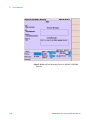
2 To set path loss value, press the Press the Config, Test
Condition and Loss softkeys sequentially. Figure 4-14 will
be displayed.
N9360A Multi UE Tester W-CDMA User Manual
4-21
4
Operating Procedures
Figure 4-14 [Configuration: Test Condition (Loss)] Screen
3 Set the "Loss" field to "On" with the CURSOR CONTROL
knob.
4 Enter the appropriate loss values in the "RF In" and "RF
Out" fields with the CURSOR CONTROL knob. These loss
values are used all through the test flow except RF tests.
5 Press the Return softkey to return to the [Initial] screen.
4-22
N9360A Multi UE Tester W-CDMA User Manual
Operating Procedures
4
Entering Channel Attenuation on the [Configuration: Test
Sequence] Screen
This section describes correction for the RF Test results in
Automatic Test. Each radio frequency channel (RFCH) path loss
can be set in the [Configuration: Test Sequence] screen. This is
the RF test correction function in addition to the loss function
in the [Configuration] screen.
As well as entering the loss values in the [Configuration] screen,
the user can also enter the attenuation values to be used to
correct the RF test results for each RFCH in the Automatic Test
mode.
Determine and enter the appropriate attenuation values,
caused by the antenna coupler, RF cable or shield case
connecting the mobile phone to the tester, for each RFCH.
The following is the procedure to accomplish the above:
1 Press the W-CDMA softkey on the [Top Menu] screen to
activate W-CDMA system. Refer to“System Selection" on
page 4-14 for more details.
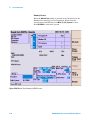
2 Press the Config softkey on the [Initial] screen and then
the Test Sequence softkey on the [Configuration] screen to
display the [Configuration: Test Sequence] screen.
N9360A Multi UE Tester W-CDMA User Manual
4-23
4
Operating Procedures
Figure 4-15 [Configuration: Test Sequence] Screen
3 Enter appropriate attenuation values, depending on the
radio frequency channel, in the "ATT In" and "ATT Out"
fields with the CURSOR CONTROL knob. These values are
effective for the RF tests in the test flow.
4 Press the Return softkey twice to return to the [Initial]
screen.
4-24
N9360A Multi UE Tester W-CDMA User Manual
Operating Procedures
4
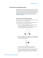
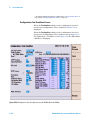
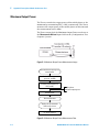
Testing Mobile Phone Using Automatic Test
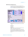
Downlink TX Power
Set the following parameters on the [Configuration: Test
Sequence] screen for downlink output power in Automatic Test:
• BS Level
• Measurement BS Level
• Openloop BS Level
• FreqError BS Level
• BER BS Level
The BS Level setting is applied to signaling steps. In RF Test,
different downlink TX powers are applied depending on
measurement items.
• Open Loop TX Power: Openloop BS Level
• Inner Loop TX Power and Max TX Power: Measurement
BS Level
• Frequency Error: FreqError BS Level
• Sensitivity/BER: BER BS Level
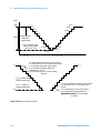
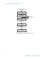
Figure 4-16 shows the condition of downlink TX power in
Automatic Test.
N9360A Multi UE Tester W-CDMA User Manual
4-25
4
Operating Procedures
Start
Location Update
Idle
Start
MS Call
Open Loop TX Power
Connection(Talk)
AMR
Talk
BS Level
MS Release
BS Call(AMR)
Inner Loop Power
ILP (Down Min)
ILP (Down Max)
ILP (Up Min)
ILP (Up Max)
ILP (10slots down)
ILP (10slots Up)
Connection(Talk)
AMR
Openloop
BS Level
Openloop
BS Level
Measurement
BS Level
Talk
Max TX Power
BS Release
EVM
BS Call(RMC)
Frequency Error
FreqError
BS Level
Connection
RMC
Sensitivity/BER
BER BS Level
RF Test
Return
BS Level
BS Release
End
I
Figure 4-16 Downlink TX Power In Automatic Test
4-26
N9360A Multi UE Tester W-CDMA User Manual
Operating Procedures
4
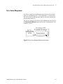
Method for Testing Mobile Phone by Automatic Test
This section describes the operation method of the Tester and a
mobile phone under the test by Automatic Test.
1 Turn on the Tester and select the W-CDMA system on the
[Top Menu] screen. Refer to “System Selection" on
page 4-14 for more details.
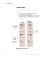
2 The [Initial] screen, shown in Figure 4-17, is displayed
after the tester has completed its initialization and
self-test routines.
Figure 4-17 [Initial] Screen
N9360A Multi UE Tester W-CDMA User Manual
4-27
4
Operating Procedures
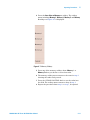
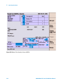
3 Set path loss values
Press the Config > Test Condition > Loss softkeys on the
[Initial] screen to display the [Configuration: Test
Condition (Loss)] screen. Specify the "Loss" field. See
Figure 4-18.
Figure 4-18 [Configuration: Test Condition (Loss)] Screen
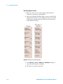
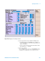
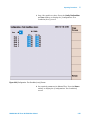
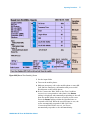
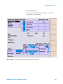
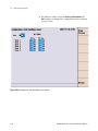
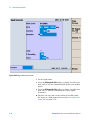
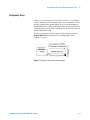
4 Set required parameters for Automatic Test.
Press the Test sequence softkey to display the
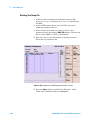
[Configuration: Test Sequence] screen. See Figure 4-19.
4-28
N9360A Multi UE Tester W-CDMA User Manual
Operating Procedures
4
Figure 4-19 [Configuration: Test Sequence] Screen
5 Set the input fields with the CURSOR CONTROL knob.
• Set "Radio System 2" to "W-CDMA" or "-----". When "-----"
is set, only sequence 1 is executed. ("Radio System 1" is
fixed to "W-CDMA".)
• Set the test flow and measurement items field to "Run"
for execution or "-----" for skip.
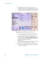
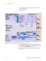
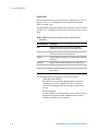
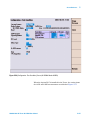
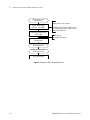
6 Set the test condition
Press the Return softkey and then the Test Condition softkey
to display the [Configuration: Test Condition] screen.
N9360A Multi UE Tester W-CDMA User Manual
4-29
4
Operating Procedures
Figure 4-20 [Configuration: Test Condition] Screen
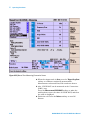
7 Set the input fields.
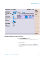
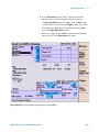
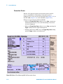
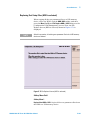
8 Start Automatic Test
Press the Return softkey twice and then the Automatic Test
softkey. The [Auto Test: Stand-by] screen as Figure 4-21 is
displayed. W-CDMA is set for Sequence 2 on the screen of
Figure 4-21.
4-30
N9360A Multi UE Tester W-CDMA User Manual
Operating Procedures
4
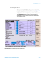
Figure 4-21 [Auto Test: Stand-by] Screen
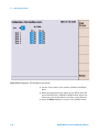
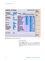
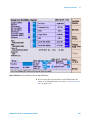
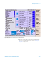
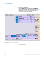
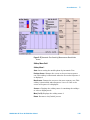
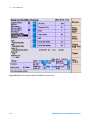
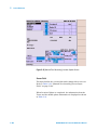
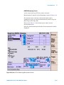
9 Press the Screen>> softkey to set the display mode. Select
the Simple, the Detail or the Value softkey. Figure 4-22 is a
Value screen showing measurement result for each
measurement item.
N9360A Multi UE Tester W-CDMA User Manual
4-31
4
Operating Procedures
Figure 4-22 [Automatic Test: Stand-by] Value Screen
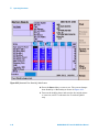
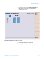
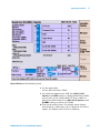
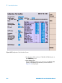
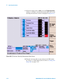
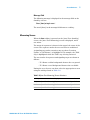
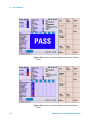
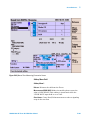
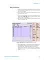
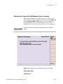
10 Press the Start softkey to start a test. The screen changes
from Stand-by to Measuring as shown in Figure 4-23.
11 Turn on the mobile phone and wait for the mobile phone
to come on, and "P" is shown at the "Location Update"
step.
4-32
N9360A Multi UE Tester W-CDMA User Manual
Operating Procedures
4
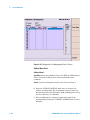
Figure 4-23 [Automatic Test: Measuring] MS Call Screen
12 At the "MS Call" step, make a call on the mobile phone.
Dial an arbitrary number and press an Off Hook button on
the mobile phone
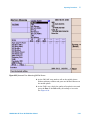
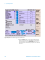
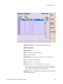
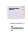
13 At the "Talk" step, check the quality of loop back voice and
press the Pass or the Fail softkey according to its result.
See Figure 4-24.
N9360A Multi UE Tester W-CDMA User Manual
4-33
4
Operating Procedures
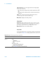
Figure 4-24 [Automatic Test: Measuring] Talk Screen
14 At the "MS Release" step, press an On Hook button on the
mobile phone to finish the call.
15 At the "BS Call (AMR)" step, press the Off Hook button on
the mobile phone to respond to the call from the Tester.
16 At the "Talk" step, the Tester returns voice back to the
mobile phone. Check the voice quality and press the Pass
or the Fail softkey according to its result.
17 At the "BS Release" step, the Tester automatically finishes
the call.
18 At the "BS Call (RMC)" step, the mobile phone
automatically responds to the call from the Tester.
4-34
N9360A Multi UE Tester W-CDMA User Manual
Operating Procedures
4
19 At the "RF Test" step, measurement items set to "Run" on
the [Configuration: Test Sequence] screen are measured.
20 At the "BS Release" step, the Tester automatically finishes
the call.
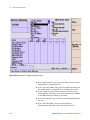
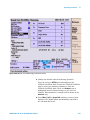
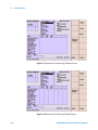
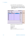
21 When Sequence 2 is set on the [Configuration: Test
Sequence] screen, a test of Sequence 2 is performed
automatically. The test goes on in the same way as
Sequence 1.
Figure 4-25 [Automatic Test: Measuring] Sequence 2 Screen
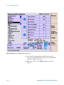
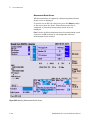
22 After completion of all tests, the screen showing
measurement results is displayed.
N9360A Multi UE Tester W-CDMA User Manual
4-35
4
Operating Procedures
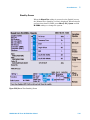
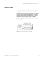
Figure 4-26 [Automatic Test: Stand-by] Measurement Result Screen
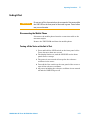
23 The user can save this test procedure in the HDD in the
tester or a USB memory device. Refer to “Saving Test
Setup File" on page 5-171.
4-36
N9360A Multi UE Tester W-CDMA User Manual
Operating Procedures
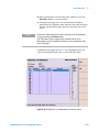
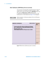
4
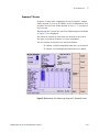
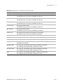
Testing Mobile Phone Using Manual Test
This section describes the operation method of the Tester and a
mobile phone under the test by Manual Test.
Refer to “Testing a Mobile Phone by Manual Test (HSDPA
Mode)" on page 4-59 about HSDPA Test by Manual Test.
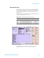
1 Turn on the Tester and select the W-CDMA system on the
[Top Menu] screen. Refer to “System Selection" on
page 4-14 about selection of the system.
2 The [Initial] screen, shown in Figure 4-27, is displayed
after the tester has completed its initialization and
self-test routines.
Figure 4-27 [Initial] Screen
N9360A Multi UE Tester W-CDMA User Manual
4-37
4
Operating Procedures
3 Set path loss values.
Press the Config > Test Condition > Loss softkeys on the
[Initial] screen to display the [Configuration: Test
Condition (Loss)] acreen. Specify the "Loss" field.
Figure 4-28 [Configuration: Test Condition (Loss)] Screen
4 Set required parameters for Manual Test.
Press the Test Condition softkey to display the
[Configuration: Test Condition] screen for required
setting on Manual Test.
4-38
N9360A Multi UE Tester W-CDMA User Manual
Operating Procedures
4
Figure 4-29 [Configuration: Test Condition] Screen
5 Set the input fields with the CURSOR CONTROL knob. Set
the "W-CDMA Mode" to "W-CDMA".
6 Start Manual Test. Press the Return softkey twice and then
the Manual Test softkey. The [Manual Test: Stand-by]
screen, Figure 4-30, is displayed.
N9360A Multi UE Tester W-CDMA User Manual
4-39
4
Operating Procedures
Figure 4-30 [Manual Test: Stand-by] Screen
7 Set the input fields.
Set the type of BS Call (AMR or RMC) to be executed
during the test at the "BS Call" input field.
8 Turn on the mobile phone. The display status changes
from Stand-by to Measuring.
4-40
N9360A Multi UE Tester W-CDMA User Manual
Operating Procedures
4
Figure 4-31 [Manual Test: Measuring] Screen for Location Update
9 After completion of location update, the display status
returns to Stand-by (Figure 4-32).
Start MS Call or BS Call. The type of BS Call is "AMR" or
"RMC" according to the setting at the "BS Call" input field
in step 7.
• To execute MS Call, perform step 10 to step 13, and then
proceed to step 25.
• To execute BS Call (AMR), perform step 14 to step 18,
and then proceed to step 25.
• To execute BS Call (RMC), perform step 19 to step 24,
and then proceed to step 25.
N9360A Multi UE Tester W-CDMA User Manual
4-41
4
Operating Procedures
Figure 4-32 [Manual Test: Stand-by] Screen After Location Update
10 Make a call on the mobile phone to start MS Call. Dial an
arbitrary and press the Off Hook button on the mobile
phone.
11 If the "Connection Wait" field on the [Configuration: Test
Condition] screen is set to any number other than 0, the
Answer softkey is displayed when manually responding to
the call from the mobile phone becomes acceptable on the
Tester. Press the Answer softkey within the specified time
to respond to MS Call. When the specified time is over, the
Tester automatically responds to MS Call. If the
"Connection Wait" field is set to 0, the tester automatically
responds to the call immediately.
12 CPICH RSCP is reported from the mobile phone when the
"CPICH RSCP" field is set to "On".
4-42
N9360A Multi UE Tester W-CDMA User Manual
Operating Procedures
4
13 At the "Connection (AMR)" step, the Tester returns voice
back to the mobile phone. Check the voice quality.
14 Also, CPICH RSCP can be measured at the "Connection
(AMR)" step. Press the Measurement CPICH RSCP softkey to
make the mobile phone report the value of CPICH RSCP,
and then the value is displayed.
15 Finish the call. Press an On Hook button on the mobile
phone to start MS Release, or press the Release softkey to
start BS Release.
16 Press the BS Call softkey to start BS Call (AMR). PRACH
Power is measured. Also, CPICH RSCP is reported from
the mobile phone when the "CPICH RSCP" field is set to
"On".
17 Respond to the call from the Tester. Press the Off Hook
button on the mobile phone.
18 At the "Connection (AMR)" step, the Tester returns voice
back to the mobile phone. Check voice quality.
19 Also, CPICH RSCP can be measured at the "Connection
(AMR)" step.
Press the Measurement CPICH RSCP softkey to make the
mobile phone report the value of CPICH RSCP, and then
the value is displayed.
20 Finish the call. Press the Release softkey to start BS
Release or press an On Hook button on the mobile phone
to start MS Release.
21 Press the BS Call softkey to start BS Call (RMC). RFCH
Power is measured. Also, CPICH RSCP is reported from
the mobile phone when the "CPICH RSCP" field is set to
"On".
22 The mobile phone automatically responds to the call from
the tester.
23 At the "Connection (RMC)" step, RF Test is executed. Start
the measurement with the following softkey operation.
• Trigger Sing/Cont : When the trigger mode is Sing, single
measurement starts when the Trigger softkey is pressed.
To change the trigger mode to continuous mode (Cont),
press the Trigger Sing/Cont softkey. When the trigger
mode is Cont, continuous measurement starts as soon
as the "Connection (RMC)" step starts.
• Trigger: Starts single measurement.
N9360A Multi UE Tester W-CDMA User Manual
4-43
4
Operating Procedures
Figure 4-33 [Manual Test: Measuring] Connection Screen
24 When the trigger mode is Cont, press the Trigger Sing/Cont
softkey to terminate continuous measurement.
Measurement values and Pass/Fail results are shown.
25 Also, CPICH RSCP can be measured at the "Connection
(RMC)" step.
Press the Measurement CPICH RSCP softkey to make the
mobile phone report the value of CPICH RSCP, and then
the value is displayed.
26 Finish the call. Press the Release softkey to start BS
Release.
4-44
N9360A Multi UE Tester W-CDMA User Manual
Operating Procedures
4
Figure 4-34 [Manual Test: Stand-by] Screen After BS Release
27 You can save this test procedure in the HDD inside the
Tester or a USB memory device. Refer to “Saving Test Setup
File" on page 5-171.
N9360A Multi UE Tester W-CDMA User Manual
4-45
4
Operating Procedures
Handover
NOTE
Install Option G00 when using the Handover function to change to GSM
system.
1 Turn on the Tester and select the W-CDMA system on the
[Top Menu] screen. Refer to “System Selection" on
page 4-14 about selection of the system.
2 The [Initial] screen as Figure 4-35 is displayed after
completion of initialization and self-test routine of the
Tester.
Figure 4-35 [Initial] Screen
4-46
N9360A Multi UE Tester W-CDMA User Manual
Operating Procedures
4
3 Set path loss values. Press the Config, Test Condition and
Loss softkeys to display the [Configuration: Test
Condition(Loss)] screen.
Figure 4-36 [Configuration: Test Condition (Loss)] Screen
4 Set required parameters for Manual Test.
Press the Return softkey to display the [Configuration: Test
Condition] screen.
N9360A Multi UE Tester W-CDMA User Manual
4-47
4
Operating Procedures
Figure 4-37 [Configuration: Test Condition] Screen
5 Set the input fields with the CURSOR CONTROL knob. Set
the GSM mode to GSM.
6 Change the Current System to GSM and set the required
parameters such as Loss value of GSM. Refer to the
N9360A Multi UE Tester GSM User Manual for GSM
settings. Return the Current System to W-CDMA after
set-up is completed.
7 Start Manual Test.
Press the Return twice and then the Manual Test softkeys to
start Manual Test. The [Manual Test: Stand-by] screen
shown in Figure 4-38 is displayed.
4-48
N9360A Multi UE Tester W-CDMA User Manual
Operating Procedures
4
Figure 4-38 [Manual Test: Stand-by] Screen
8 Set the input fields.
Set the "BS Call" field to "RMC".
9 Set required parameters for GSM. Press More (1 of 2),
System>> and GSM softkeys to display Manual Test (GSM)
screen. Refer to the N9360A Multi UE Tester GSM User
Manual for GSM settings. Press More (1 of 2), System>> and
W-CDMA softkey to return to W-CDMA.
10 Turn on the mobile phone. The display status changes
from Stand-by to Measuring. After completion of location
update, the display status returns to Stand-by.
N9360A Multi UE Tester W-CDMA User Manual
4-49
4
Operating Procedures
Figure 4-39 [Manual Test: Measuring] Location Update Screen
11 Press the BS Call softkey to start BS Call (RMC). RFCH
Power is measured. Also, CPICH RSCP is reported from
the mobile phone when the CPICH RSCP field is set to On.
The mobile phone automatically responds to the call from
the Tester.
4-50
N9360A Multi UE Tester W-CDMA User Manual
Operating Procedures
4
Figure 4-40 [Manual Test: Measuring] Connection Screen
12 Change the channel with the following operation.
Move the cursor to RFCH input field and press the
CURSOR CONTROL knob. Rotate the CURSOR CONTROL
knob to select the channel for handover. Press the
CURSOR CONTROL knob. Then, the Handover step is
highlighted and the channel changes to the selected
channel. When handover is completed, P is shown at the
Handover step.
13 Press More (1 of 2) > System H.O. softkeys to start system
handover. The mobile phone automatically responds to
the call from the Tester.
N9360A Multi UE Tester W-CDMA User Manual
4-51
4
Operating Procedures
Figure 4-41 [Manual Test (GSM): Measuring] Screen
14 Voice check and performance measurement can be
executed on the GSM screen. Refer to the N9360A Multi
UE Tester GSM User Manual.
15 Finish the call. Press the Release softkey to start BS
Release.
4-52
N9360A Multi UE Tester W-CDMA User Manual
Operating Procedures
4
Figure 4-42 [Manual Test: Stand-by] Screen After BS Release
16 The user can save this test procedure in the HDD inside
the tester or a USB memory device. Refer to “Saving Test
Setup File" on page 5-171.
N9360A Multi UE Tester W-CDMA User Manual
4-53
4
Operating Procedures
Emergency Call
NOTE
To test the emergency call function, place the mobile phone and the
Tester where the radio signal (electromagnetic wave) base station of a
cell phone operator does not propagate, such as in a shield room, an
anechoic chamber, etc.
Execute the test of emergency call without any USIM.
1 Turn on the Tester and select the W-CDMA system on the
[Top Menu] screen. Refer to "“System Selection" on
page 4-14 about selection of the system.
2 The [Initial] screen as Figure 4-43 is displayed after
completion of initialization and self-test routine of the
Tester.
Figure 4-43 [Initial] Screen
4-54
N9360A Multi UE Tester W-CDMA User Manual
Operating Procedures
4
3 Step 3.Set path loss values. Press the Config, Test Condition
and Loss softkeys to display the [Configuration: Test
Condition(Loss)] screen.
Figure 4-44 [Configuration: Test Condition (Loss)] Screen
4 Set required parameter for Manual Test. Press the Return
softkey to display the [Configuration: Test Condition]
screen.
N9360A Multi UE Tester W-CDMA User Manual
4-55
4
Operating Procedures
Figure 4-45 [Configuration: Test Condition] Screen
5 Set the input fields with the CURSOR CONTROL knob. Set
the GSM mode to GSM.
6 Start Manual Test.
Press the Return softkey twice and then the Manual Test
softkey. The Manual Test: Stand-by screen shown in
Figure 4-46 is displayed.
4-56
N9360A Multi UE Tester W-CDMA User Manual
Operating Procedures
4
Figure 4-46 [Manual Test: Stand-by] Screen
7 Set the input fields.
8 Turn on the mobile phone.
9 Make an emergency call on the mobile phone to start MS
Call. Dial the emergency call number and press an Off
Hook button on the mobile phone.
10 If the "Connection Wait" field on the: Test Condition
screen is set to any number other than 0, the Answer
softkey is displayed when manually responding to the call
from the mobile phone becomes accepted on the tester.
Press the Answer softkey within the specified time to
respond to MS Call. When the specified time is over, the
tester automatically responds to MS Call. If the
"Connection Wait" field is set to 0, the Tester
automatically responds to the call immediately.
N9360A Multi UE Tester W-CDMA User Manual
4-57
4
Operating Procedures
11 When MS Call connects, the screen in Figure 4-47 is
displayed. "Emergency Call" is displayed at the "Dialed
No.:" field on the screen. CPICH RSCP is reported from the
mobile phone when the "CPICH RSCP" field is set to "On".
Figure 4-47 [Manual Test: Measuring] Emergency Call Screen
12 At the "Connection (AMR)" step, the Tester returns voice
back to the mobile phone. Check the voice quality.
13 Also, CPICH RSCP can be measured at the "Connection
(AMR)" step. Press the Measurement CPICH RSCP softkey to
make the mobile phone report the value of CPICH RSCP,
and then the value will be displayed.
14 Finish the call.
Press an On Hook button on the mobile phone to start MS
Release, or press the Release softkey to start BS.
15 The user can save this test procedure in the HDD inside
the Tester or a USB memory device. Refer to “Saving Test
Setup File" on page 5-171.
4-58
N9360A Multi UE Tester W-CDMA User Manual
Operating Procedures
4
Testing a Mobile Phone by Manual Test (HSDPA Mode)
NOTE
Install the Option W06 when using the HSDPA function.
This section describes the operation method of the Manual Test
HSDPA mode.
1 Turn on the Tester and select the W-CDMA system on the
Top menu screen. Refer to “System Selection" on
page 4-14 about selection of the system.
2 The [Initial] screen as Figure 4-48 is displayed after
completion of initialization and self-test routine of the
Tester.
Figure 4-48 [Initial] Screen
N9360A Multi UE Tester W-CDMA User Manual
4-59
4
Operating Procedures
3 Set path loss values. Press the Config, Test Condition and
Loss softkeys to display the [Configuration: Test
Condition(Loss)] screen.
Figure 4-49 [Configuration: Test Condition (Loss)] Screen
4 Step 4.Set required parameters for Manual Test. Press the
Return softkey to display the [Configuration: Test
Condition] screen.
4-60
N9360A Multi UE Tester W-CDMA User Manual
Operating Procedures
4
Figure 4-50 [Configuration: Test Condition] Screen (HSDPA)
5 Set the W-CDMA Mode to HSDPA.
Set the input fields with the CURSOR CONTROL knob.
6 Start Manual Test.
Press the Return softkey twice and then the Manual Test
softkey. The [Manual Test: Stand-by] screen as Figure 4-51
is displayed.
N9360A Multi UE Tester W-CDMA User Manual
4-61
4
Operating Procedures
Figure 4-51 [Manual Test: Stand-by] Screen (HSDPA)
4-62
N9360A Multi UE Tester W-CDMA User Manual
Operating Procedures
4
7 Set the input fields.
Turn on the mobile phone. The display status changes
from Stand-by to Measuring.
Figure 4-52 [Manual Test: Measuring] Location Update Screen (HSDPA)
N9360A Multi UE Tester W-CDMA User Manual
4-63
4
Operating Procedures
8 After completion of location update, the display status
returns to Stand-by.
Start BS Call.
Figure 4-53 [Manual Test: Stand-by] After Location Update Screen (HSDPA)
9 Press the BS Call softkey to start BS Call. RFCH Power is
measured. Also, CPICH RSCP is reported from the mobile
phone when the CPICH RSCP field is set to On.
10 The mobile phone automatically responds to the call from
the Tester.
4-64
N9360A Multi UE Tester W-CDMA User Manual
Operating Procedures
4
11 At the Connection step, RF Test is executed. Start the
measurement with the following softkey operation.
• Trigger Sing/Cont: When the trigger mode is Sing, single
measurement starts when the Trigger softkey is pressed.
To change the trigger mode to continuous mode (Cont),
press the Trigger Sing/Cont softkey.
When the trigger mode is Cont, continuous measurement
starts as soon as the Connection step starts.
Figure 4-54 [Manual Test: Measuring] Connection Screen (HSDPA)
N9360A Multi UE Tester W-CDMA User Manual
4-65
4
Operating Procedures
12 When the trigger mode is Cont, press the Trigger Sing/Cont
softkey to terminate continuous measurement.
Measurement value and Pass/Fail results are shown.
13 Also, CPICH RSCP can be measured at the Connection step.
Press the Measurement CPICH RSCP softkey to make the
mobile phone report the value of CPICH RSCP, and then
the value will be displayed.
14 Finish the call. Press the Release softkey to start BS
Release.
Figure 4-55 [Manual Test: Stand-by] After BS Release Screen (HSDPA)
15 You can save this test procedure in the HDD inside the
Tester or a USB memory device. Refer to “Saving Test
Setup File" on page 5-171.
4-66
N9360A Multi UE Tester W-CDMA User Manual
Operating Procedures
4
Testing a Mobile Phone by TX Analyzer
This section describes the method to test on the mobile phone
with the TX Analyzer. Using the TX Analyzer, measurements are
executed without the signaling process.
1 Turn on the Tester and select the W-CDMA system on the
[Top Menu] screen. Refer to “System Selection" on
page 4-14 about selection of the system.
2 The [Initial] screen as Figure 4-56 is displayed after
completion of initialization and self-test routine of the
Tester.
Figure 4-56 [Initial] Screen
N9360A Multi UE Tester W-CDMA User Manual
4-67
4
Operating Procedures
3 Set path loss values. Press the Config, Test Condition and
Loss softkeys to display the [Configuration: Test
Condition(Loss)] screen.
Figure 4-57 [Configuration: Test Condition (Loss)] Screen
4 Set the test condition. Press the Return softkey to display
the [Configuration: Test Condition] screen. When the
Option W07 is installed, the screen as Figure 4-58 is
displayed.
4-68
N9360A Multi UE Tester W-CDMA User Manual
Operating Procedures
4
Figure 4-58 [Configuration: Test Condition] Screen
5 Set the input fields except the "BS Level", "BER Frames",
"Averaging", "Date", "Loopback Delay" and "TPC
Algorithm".
N9360A Multi UE Tester W-CDMA User Manual
4-69
4
Operating Procedures
6 Start a test by TX Analyzer.
Press the Return softkey twice and then the TX Analyzer
softkey. The TX Analyzer: Stand-by screen in Figure 4-59
is displayed. Figure 4-59 is the screen of the tester in
which the W07 option is not installed.
Figure 4-59 [TX Analyzer: Stand-by] Screen
7 Set the input fields.
4-70
N9360A Multi UE Tester W-CDMA User Manual
Operating Procedures
4
8 Start a test with the following softkey operations:
• Trigger Sing/Cont: When the trigger mode is Sing, single
measurement starts when the Trigger softkey is pressed.
To change the trigger mode to continuous mode (Cont),
press the Trigger Sing/Cont softkey.
When the trigger mode is Cont, continuous measurement
starts as soon as the [TX Analyzer: Stand-by] screen is
displayed.
Figure 4-60 [TX Analyzer: Measuring] Screen
N9360A Multi UE Tester W-CDMA User Manual
4-71
4
Operating Procedures
9 When the trigger mode is Cont, press the Trigger Sing/Cont
softkey to terminate continuous measurement. The screen
showing measurement results is displayed in Figure 4-61.
Figure 4-61 [TX Analyzer: Stand-by] Measurement Result Screen
10 The user can save this test procedure in the HDD inside
the Tester or a USB memory device. Refer to “Saving Test
Setup File" on page 5-171.
4-72
N9360A Multi UE Tester W-CDMA User Manual
Operating Procedures
4
Testing a Mobile Phone by Signal Generator
This section describes the testing of mobile phones using the
Signal Generator capabilities of the tester.
1 Turn on the Tester and select the W-CDMA system on the
[Top Menu] screen. Refer to “System Selection" on
page 4-14 about selection of the system.
2 The [Initial] screen as Figure 4-62 is displayed after
completion of initialization and self-test routine of the
Tester.
Figure 4-62 [Initial] Screen
N9360A Multi UE Tester W-CDMA User Manual
4-73
4
Operating Procedures
3 Set path loss values. Press the Config, Test Condition and
Loss softkeys to display the [Configuration: Test Condition
(Loss)] screen.
Figure 4-63 [Configuration: Test Condition (Loss)] Screen
4-74
N9360A Multi UE Tester W-CDMA User Manual
Operating Procedures
4
4 Set the test condition. Press the Return softkey to display
the [Configuration: Test Condition] screen. When the
Option W07 is installed, the screen as Figure 4-64 is
displayed.
Figure 4-64 [Configuration: Test Condition] Screen
5 Set the Band fields.
6 Start a test by Signal Generator. Press the Return softkey
twice and then the Signal Generator softkey. The [Signal
Generator] screen as Table 4-65 is displayed.
N9360A Multi UE Tester W-CDMA User Manual
4-75
4
Operating Procedures
Figure 4-65 [Signal Generator] Screen
7 Set the input fields.
8 Press the RF Output On/Off softkey to change "On/Off" state
from "Off" to "On" for transmitting RF signal to the mobile
phone.
9 Press the RF Output On/Off softkey to change "On/Off" state
from "On" to "Off" for terminating the test by Signal
Generator.
10 The user can save this test procedure in the HDD inside
the Tester or a USB memory device. Refer to “Saving Test
Setup File" on page 5-171.
4-76
N9360A Multi UE Tester W-CDMA User Manual
Operating Procedures
4
Ending A Test
CAUTION
Do not turn off the Line switch on the rear panel of the tester while
the LINE LED on the front panel of the tester is green. Tester failure
may occur otherwise.
Disconnecting the Mobile Phone
Disconnect the mobile phone from the connection cable or the
antenna coupler.
Remove the TEST USIM card from the mobile phone.
Turning off the Tester at the End of Test
1 Press and hold the LINE switch on the front panel of the
Tester for more than one second.
2 The display blacks out, and the LINE LED on the front
panel turns to orange.
3 The power is now turned off except for the reference
oscillator in the tester.
4 Turn off the Line switch on the rear panel of the tester to
turn off the reference oscillator.
5 All power including the reference oscillator is now turned
off and the LINE LED goes off.
N9360A Multi UE Tester W-CDMA User Manual
4-77
4
Operating Procedures
THIS PAGE IS INTENTIONALLY LEFT BLANK.
4-78
N9360A Multi UE Tester W-CDMA User Manual
5
Screen Reference
Screen Flow Chart 5-2
Top Menu Screen 5-3
Configuration Screen 5-7
Firmware Update Screen 5-13
Initial Screen 5-24
Return to Menu Screen 5-27
PRESET Select Mode Screen 5-28
Automatic Test 5-30
Manual Test 5-59
TX Analyzer 5-126
Signal Generator 5-140
Configuration 5-145
In this chapter, each screen in the tester display is explained in
detail. This includes the operational features and the functional
softkeys activated in each screen.
Agilent Technologies
5-1
Screen Reference
5
Screen Flow Chart
Figure 5-1 shows the screen flow chart for each function mode.
Each rectangle represents one screen with a different function
mode and testing status.
Top
Me n u
Confi
gurat
ion
Select
“GSM” or
"W-CDMA"
Refer to
“N9360A Multi UE Tester
GSM User Manual”
or
“N9360A Multi UE Tester
cdma2000 User Manual”
Netw
ork
FirmwSetting
Upda are
te
Select
"W-CDMA"
P
SoftkInitial
e y Me
nu
SoftkInitial
e y Me
nu
Upda
t
Flash e
est
lock
atic T
utom
e y Un
A
lk
e
n
a
Meas
urin
Meas
uringValue g
Meas
D
e
t
ring ail
Simpule
l Tes
lkey L
ock
Stand
Sta
Va -by
Stand Dentda-by lue
il
Simp-leby
Meas
urin
Meas
uringValue g
Meas
D
e
t
ring ail
Simpule
Stand
Sta
Va -by
Stand Dentda-by lue
il
-by
Simple
a
Manu
Pane
al Te
Ma n u
st
Stand
-by
t
Meas
uring
Stand
-by
Meas
nalyz
TX A
uring
TX A
er
Stand
-by
er
nalyz
Meas
uring
Stand
-by
Meas
Sign
uring
a l Ge
to
nera
r
S na
Genig
eratlo
r
tor
ner a
a l Ge
Sign
S na
Genig
eratlo
r
ig
Conf
Confi
gu
ration
Config
uratio
n
n
uratio
Netw
Settinork
g
File
M
a
n
Cond ageme
Test
ition
nt
Sequ
ence
Loss
Test
Netw
Settinork
g
ManaFile
C
g
o
e
n
Test
dition ment
Sequ
ence
Loss
Test
Figure 5-1 Screen Structure Chart
5-2
N9360A Multi UE Tester W-CDMA User Manual
Screen Reference
5
Top Menu Screen
The [Top Menu] screen shown in Figure 5-2 is displayed after
the tester completes its power on sequence.
This screen is used to select a system option or the
[Configuration] screen.
The system options available are GSM, W-CDMA and cdma2000.
Menu
GSM
cdma2000
W-CDMA
Configuration
Firmware Update
Figure 5-2 Selectable Systems
NOTE
This manual describes only the W-CDMA system. Refer to the Agilent
N9360A Multi UE Tester GSM Option User Manual and the Agilent
N9360A Multi UE Tester cdma2000 Option User Manual for information
about the test functions of GSM and cdma2000 systems.
N9360A Multi UE Tester W-CDMA User Manual
5-3
5
Screen Reference
Figure 5-3 [Top Menu] Screen
5-4
N9360A Multi UE Tester W-CDMA User Manual
Screen Reference
5
Softkey Menu Field
Softkey Menu 1
GSM
Selects the GSM system. After the system is selected, the Tester
is automatically rebooted, and then displays the [Initial] screen
for GSM system. This softkey is activated when the GSM system
is installed in the Tester.
W-CDMA
Selects the W-CDMA system. After the system is selected, the
Tester is automatically rebooted, and then displays the [Initial]
screen for W-CDMA system. This softkey is activated when the
W-CDMA system is installed in the Tester.
CDMA2000
Selects the cdma2000 system. After the system is selected, the
Tester is automatically rebooted, and then displays the [Initial]
screen for cdma2000 system. This softkey is activated when the
cdma2000 system is installed in the Tester.
More (1 of 2)
Displays the softkey menu 2.
Config
Displays the [Configuration] screen.
Softkey Menu 2
Print Screen
Prints a hardcopy of the screen or saves a screen image into a
USB memory device depending on the setting of the "Printer"
input field on the [Configuration] screen.
Reboot
Aborts a current system and returns to the [Top Menu] screen
after reboots the Tester.
More (2 of 2)
Returns to the softkey menu 1.
N9360A Multi UE Tester W-CDMA User Manual
5-5
5
Screen Reference
NOTE
When the AutoBoot function is set to "FUNC GSM", "FUNC W-CDMA" or
"FUNC CDMA2000", the Tester automatically selects the GSM, W-CDMA
or cdma2000 system mode if no softkey is pressed within the specified
time (10 to 60 seconds). When the Tester is shipped, the AutoBoot
function is set to "None". Refer to the “AutoBoot" on page 5-10 for
details.
Screen Field
The firmware name, revision number currently installed and
serial number are shown in this field.
Message Field
The following message is displayed in the message field:
"Select a Radio System or Configuration."
5-6
N9360A Multi UE Tester W-CDMA User Manual
Screen Reference
5
Configuration Screen
When the Config softkey is pressed on the [Top Menu] screen,
the [Configuration] screen is displayed. When the Option E00
and the Option E01 are not installed in the Tester, the
[Configuration] screens are as Figure 5-4.
Figure 5-4 [Configuration] Screen (with Option E00/E01)
N9360A Multi UE Tester W-CDMA User Manual
5-7
5
Screen Reference
Softkey Menu Field
Softkey Menu
Print Screen
Prints a hardcopy of the screen or saves a screen image into a
USB memory device depending on the setting of the "Printer"
input field on the [Configuration] screen.
FW Update
Displays the [Firmware Update] screen.
Network Setting
Displays the [Network Setting] screen.
Option Install
Uses for installation of an option function such as G00 and W00.
Option Backup
Backs up the installed option functions.
Return
Returns to the [Top Menu] screen.
If the Option E00 and Option E02 are not installed, setting items
for GP-IB are grayed out (disabled) as Figure 5-5.
Figure 5-5 Part of [Configuration] screen (without Option E00 and E02)
When the Option E01 is not installed, setting items for the serial
port are grayed out (disabled) as Figure 5-6.
5-8
N9360A Multi UE Tester W-CDMA User Manual
Screen Reference
5
Figure 5-6 Part of [Configuration] screen (without Option E01)
Screen Field
The following input fields need to be set in order to start a new
test. The setting required is described in Table 5-1.
Table 5-1 [Configuration] Screen Input Field
Input Field
Description
Reference
Selects a reference signal from "Internal" and "External".
• Internal: The internal 10 MHz reference signal is used.
• External: The external 10 MHz reference signal is used. The external 10 MHz reference signal
must be supplied to the "10 MHz Reference IN" connector on the rear panel.
Serial Port
Sets the communication condition of the serial port (RS-232C) to use remote control. The option E01 is
required to use this function.
• Baud Rate: Sets communication speed to 9600, 19200, 38400, 57600 or 115200 bits per second.
• Data Length: Sets the data length to 7 or 8 bits.
• Stop Bits: Sets the stop bit length to 1, 1.5 or 2 bits.
• Parity: Sets the parity check mode to "None", "Odd" or "Even".
• Xcontrol: Sets the flow control to "None" or "Xon/Xoff".
GPIB †
Sets the communication condition of the GP-IB port to use remote control. The option E00 or option
E02 is required to use this function.
• Addr: Sets the GP-IB address. The allowable range is from 1 to 15.
• EOI: Sets EOI control. Select "On" or "Off".
• On: Enables EOI control. (Terminator setting is ignored.)
• Off: Disables EOI control. (Terminator setting is valid.)
Reboot the Tester after changing the GP-IB setting.
Terminator
• Sets the terminator of the output text data to "CR", "LF" or "CR+LF". This is the setting for remote
control using the serial interface, Ethernet and GP-IB. (The terminator of the input data is always
"LF".
• The Terminator of input text data for GPIB option E00 : set to CR+LF for GPIB option E02 : set to LF.
N9360A Multi UE Tester W-CDMA User Manual
5-9
5
Screen Reference
Table 5-1 [Configuration] Screen Input Field
Input Field
Description
Printer
Sets the destination to which the print data is sent to "USB Memory" or "EPSON PM-G800", when the
Print Screen softkey is pressed.
• USB Memory: Saves the image of the screen into a USB memory device. The file format is PNG
(Portable Network Graphics).
• EPSON PM-G800: Prints a hardcopy of the screen with the specified printer
Beeper
Sets beep.
Selects "On" or "Off".
• On: Beeps for each step of operation.
• Off: Beeps only for noticing some errors and warnings.
AutoBoot
Specifies the system for automatic boot when a certain time (time-out period) has passed since the
[Top Menu] screen was displayed.
• Application: Selects a system from the followings:
• None: No automatic boot occurs.
• FUNC GSM: Boots the GSM option.
• FUNC W-CDMA: Boots the W-CDMA option.
• FUNC CDMA2000: Boots the cdma2000 option.
• Timer: Sets the time out timer (10 to 60 seconds) or "----". The timer is stopped when any softkey
is pressed.
• ----: Disables the setting for the time out timer.
• 10 to 60: Sets the time-out timer.
Date/Time †
Sets the current date and time in the following format.
• YYYY: Sets the year. The allowable range is from 1990 to 2037.
• MM: Sets the month. The allowable range is from 01 to 12.
• DD: Sets the day. The allowable range is from 01 to 31.
• HH: Sets the hour. The allowable range is from 00 to 23.
• MM: Sets the minute. The allowable range is from 00 to 59.
Option Install
Installs Option. Set the 16 digits option key and press the Option Install softkey to install an option.
When using this function, do not insert a USB memory device.
† The changing magnification softkey is available. Refer to “Changing Magnification
Softkey" on page 4-13.
In addition, this screen displays the following information:
• Serial number
• Revision number of RF CPU software.
• Revision number of MC-1x CPU software. (Only when the
C00 and C01 options are installed.)
• Revision number of 1xEV-DO CPU software. (Only when the
C00, C01 and C02 option are installed.)
5-10
N9360A Multi UE Tester W-CDMA User Manual
Screen Reference
5
• Options that are already installed.
Option Installation/Backup
On the [Configuration] screen, you can install/back up option
functions. such as C01, C02, W00, and G00.
NOTE
To install options, a suitable option key for the option is required. For
further information, contact the Agilent Sales Department or a licensed
distributor.
Option Install
Install option functions to the Tester. There are two way to
install it. One is using a USB memory device. The other is not
using a USB memory device.
Using a USB memory Device
Prepare a USB memory device which contains an option key.
1 Press the Config softkey on the [Top Menu] screen to
display the [Configuration] screen.
2 Insert a USB memory device which contains the option key
to the USB connector on the front panel of the Tester.
3 Press the Option Install softkey.
4 The option number is added in the "Option" field in the
information field. Remove the USB memory device from the
Tester.
Unusing a USB memory Device
Prepare the 16 digits option key.
1 Press the Config softkey on the [Top Menu] screen to
display the [Configuration] screen.
2 Sets the 16 digits option key to the Option Install field with
the CURSOR CONTROL knob.
3 Press the Option Install softkey.
4 The option number is added in the "Option" field in the
information field.
N9360A Multi UE Tester W-CDMA User Manual
5-11
5
Screen Reference
Option Backup
Before Back up option information, prepare a USB memory
device.
1 Press the Config softkey on the [Top Menu] screen to
display the [Configuration] screen.
2 Insert a USB memory device into the USB connector on the
front panel of the Tester.
3 Press the Option Backup softkey.
4 Confirm "Option Backup complete!" message on the Message
field of the screen, and remove the USB memory device from
the Tester.
5-12
N9360A Multi UE Tester W-CDMA User Manual
Screen Reference
5
Firmware Update Screen
Insert a USB memory device which contains the firmware to the
USB connector on the front panel of the Tester.
Press the Config softkey on the [Top Menu] screen, and press the
FW Update softkey. The [Firmware Update] Screen as Figure 5-7
is displayed.
On this screen, the following information is displayed:
• Revision:
Displays the current revision and the revision of the
firmware in the USB memory device.
• "?.??.??":
Indicates that there is no file in the USB memory device for
firmware update.
• "-.--.--" or "*.**.**":
Indicates that the firmware is not installed in the Tester.
• "(complete)":
Indicates that the firmware, which is contained in the USB
memory device, is updated completely. It is displayed in the
USB version display area.
N9360A Multi UE Tester W-CDMA User Manual
5-13
5
Screen Reference
Figure 5-7 [Firmware Update] Screen
5-14
N9360A Multi UE Tester W-CDMA User Manual
Screen Reference
5
Softkey Menu Field
Softkey Menu 1
Update Menu: Updates the Top Menu functions.
Press this softkey to update the Top Menu functions after
inserting the USB memory device contained the firmware.
Restart the Tester after updating the Top Menu functions.
Update Func Tester: Updates the Function Tester functions.
Press this softkey to update the Function Tester functions after
inserting the USB memory device contained the firmware.
More (1 of 3) : Displays the Softkey Menu 2.
Return: Return to the [Configuration] screen.
Softkey Menu 2
Print Screen: Prints a hardcopy of the screen or stores the screen
image in a USB memory device, according to the "Printer" field
on the [Configuration] screen.
Update SYSTEM: Updates the system functions. Press this softkey
to update the system function after inserting the USB memory
device contained the system functions. After updating the
system functions, restarting the Tester may be required,
depending on the type of the update.
Update Flash: Displays the [Update Flash] Screen.
More (2 of 3): Displays to the Softkey Menu 3.
Softkey Menu 3
Clear HDD File: This softkey is unavailable.
Reload List: This softkey is unavailable.
Update Type: This softkey is unavailable.
More (3 of 3): Returns to the Softkey Menu 1.
N9360A Multi UE Tester W-CDMA User Manual
5-15
5
Screen Reference
Message Field
Depending on the situation, the following message is displayed
in the message field:
• Press [Update xxxx] to update.
This massage is displayed when there is a firmware in the
USB memory device.
• USB memory is not inserted.
• No update files exists in the inserted USB memory device.
• Processing... [Don't remove a USB memory!]
• Completed!
• FW-Update failed [Error number]
NOTE
5-16
Before pressing the FW Update softkey, make sure that the appropriate
USB memory device is inserted into the USB connector.
N9360A Multi UE Tester W-CDMA User Manual
Screen Reference
5
Update Flash Screen
Insert a USB memory device that contains the firmware to the
USB connector on the front panel of the Tester.
Press the Config softkey on the [Top menu] screen, and press the
FW Update, More (1 of 3) and Update Flash softkeys. The [Update
Flash] Screen as Figure 5-8 is displayed.
On this screen, the following information is displayed.
• Revision:
Displays the current revision and the revision of the
firmware in the USB memory device.
• "?.??.??":
Indicates that there is no file in the USB memory device for
firmware update.
• "-.--.--" or"*.**.**:
Indicates that the firmware is not installed in the Tester.
• "(complete)":
Indicates that the firmware, which is contained in the USB
memory device, is updated completely. It is displayed in the
USB version display area.
N9360A Multi UE Tester W-CDMA User Manual
5-17
5
Screen Reference
Figure 5-8 [Update Flash] Screen
5-18
N9360A Multi UE Tester W-CDMA User Manual
Screen Reference
5
Softkey Menu Field
Softkey Menu 1
Update MC-1x : Updates the MC-1x functions.
Pressing this softkey after inserting the USB memory device
with the firmware for the MC-1x functions executes the update.
Update 1xEV-DO: Updates the 1xEV-DO functions.
Pressing this softkey after inserting the USB memory device
with the firmware for the 1xEV-DO functions executes the
update.
More (1 of 2): Displays the Softkey Menu 2.
Return: Return to the [Firmware Updater] screen.
Softkey Menu 2
Print Screen: Prints a hardcopy of the screen or stores the screen
image in a USB memory device, according to the "Printer" field
on the [Configuration] screen.
More (2 of 2): Returns to the Softkey Menu 1.
Message Field
Depending on the situation, the following message is displayed
in the message field:
• Press [Update xxxx] to update.
This massage is displayed when there is a firmware in the
USB memory device.
• USB memory is not inserted.
• No update files exists in the inserted USB memory device.
• Processing... [Don't remove a USB memory!]
• Completed!
• FW-Update failed [Error number]
NOTE
Before pressing the Update Flash softkey, make sure that the appropriate
USB memory device is inserted into the USB connector.
N9360A Multi UE Tester W-CDMA User Manual
5-19
5
Screen Reference
Network Setting Screen
On the [Network Setting] screen, you can configure network
settings.
When the Network Setting softkey on the [Configuration] screen
is pressed, the [Network Setting] Screen as Figure 5-9 is
displayed.
This screen allows you to configure the following settings:
• IP Address
• CIDR (Subnet Mask)
• Gateway
Figure 5-9 [Network Setting] Screen
5-20
N9360A Multi UE Tester W-CDMA User Manual
Screen Reference
5
Softkey Menu
Print Screen: Prints a hardcopy of the screen or stores the screen
image in a USB memory device, according to the "Printer" field
on the [Configuration] screen.
Apply Address: Applies the changes of "IP Addr", "Mask", "Default
Gateway", "Host/Net", "Gateway" and "CIDR" to the Tester. This
softkey is not activated when the [Network Setting] screen is
displayed and no setting is changed. This softkey is activated
when any input field is changed. After applying the settings,
this softkey is inactivated again.
Cancel: Returns to the [Configuration] screen. Values changed
before pressing the Apply Address softkey are reverted to the
former values.
Screen Field
The following input fields need to be set for a new test according
to the following description of Table 5-2.
Table 5-2 [Network Setting] Screen Input Field
Input Field
Description
IP Addr
Sets the IP address of the Tester. Allowable setting value is as follows:
1.0.0.1 to 223.255.255.255 (From 192.168.1.1 to 192.168.1.255 are unavailable to setting.)
• The IP address setting supports Class A through Class C.
• The Tester does not support Class D (multicast address) and Class E (reserved address).
• The default IP address is "192.168.0.1".
• If the IP address setting fails, "Invalid" is displayed in the Status field.
• Changes to the IP address is effective after pressing the Apply Address softkey.
CIDR
(Mask)Sets the subnet mask in CIDR format. Allowable setting value is as follows:
1 to 31
• The default mask value is 24 (255.255.255.0).
• If the mask value setting fails, "Invalid" is displayed in the Status field.
• Changes to the mask setting is effective after pressing the Apply Address softkey.
Refer to “Appendix A Input Fields and Allowable Choices or Ranges" on page A-1 for details.
N9360A Multi UE Tester W-CDMA User Manual
5-21
5
Screen Reference
Table 5-2 [Network Setting] Screen Input Field
Input Field
Description
Default Gateway Sets active or inactive of the Default Gateway setting, and sets the Default Gateway address. The
allowable settings are as follows:
• None: Default Gateway setting is inactivated.
• ACT: Default Gateway setting is activated.
When "None" is selected, the address setting field is grayed out and inactivated.
1.0.0.1 to 223.255.255.255 (From 192.168.1.1 to 192.168. 1.255 are unavailable to setting.)
• The IP address setting supports Class A through Class C.
• The Tester does not support Class D (multicast address) and Class E (reserved address).
• The Default Gateway setting is valid when you set the allowable Default Gateway address, and the
Tester and the Default Gateway belong to the same network.
• When the Tester and Default Gateway do not belong to the same network, "Unreachable" is
displayed in the Status field because the routing from the Tester cannot be resolved.
• If the Default Gateway is set to "None" when booting, the address is displayed as (0.0.0.0), which
means invalid.
• When the Default Gateway setting fails, "Invalid" is displayed in the Status field.
• The Default Gateway setting is effective after pressing the Apply Address softkey.
Setting
1 to 5
Sets "Act/None" (active/inactive) of gateway settings from 1 to 5. The allowable setting is as follows:
• None: The Gateway setting is inactivated.
• ACT: The Gateway setting is activated.
• The Gateway setting is effective after pressing the Apply Address softkey.
When "None" is selected, the address setting field is grayed out and unavailable.
Host/Net
Sets the destination host or network addresses for gateway setting from 1 to 5. Allowable settings are
as follows:
• When Host address is specified (When the CIDR is set to None.):
• 1.0.0.1 to 223.255.255.255 (From 192.168.1.1 to 192.168.1.255 are unavailable to setting.)
• When Network address is specified (When the CIDR is not set to None):
• 1.0.0.0 to 223.255.255.255 (From 192.168.1.0 to 192.168.1.255 are unavailable to setting.)
• The IP address setting supports Class A through Class C.
• The Tester does not support Class D (multicast address) and Class E (reserved address).
• When the Gateway setting fails, "Invalid" is displayed in the Status field.
• The Host/Net setting is effective after pressing the Apply Address softkey.
• If the CIDR is set to "None", the Host/Net setting is recognized as a host address.
• If the CIDR is set to value other than "None", the Host/Net setting is recognized as the network
address. In this case, the address of Host part is set to "0". If it specifies the value other than "0",
"Invalid" is displayed in the Status field.
• The address setting is automatically changed to 1.0.0.1 when the address was set to 1.0.0.0 and the
Host/Net setting is changed from network to host.
5-22
N9360A Multi UE Tester W-CDMA User Manual
Screen Reference
5
Table 5-2 [Network Setting] Screen Input Field
Input Field
Description
Gateway
Sets the Gateway addresses for gateway setting from 1 to 5. Allowable settings are as follows:
1.0.0.1 to 223.255.255.255 (From 192.168.1.1 to 192.168.1.255 are unavailable to setting.)
• The IP address setting supports Class A through Class C.
• The Tester does not support Class D (multicast address) and Class E (reserved address).
• The gateway setting is valid when you set the allowable address, and the Tester and the Gateway
belong to the same network.
• If the Gateway is set to None when booting, the address is displayed as (0.0.0.0), which means
invalid.
• When the Tester and Gateway do not belong to the same network, "Unreachable" is displayed in
the Status field.
• The Gateway setting is effective after the pressing the Apply Address softkey.
CIDR
Sets the subnet masks for the destination address in CIDR format from Setting 1 to 5. Allowable setting
values are as follows:
• None or 1 to 31
• When the CIDR is set to "None", the "Host/Net" setting is recognized as a host address.
• When the CIDR is set to value other than "None", the "Host/Net" setting is recognized as network
address.
• If the "Gateway" setting is disabled when booting, "None" is displayed in the CIDR field.
• Changes to the mask setting is effective after pressing the Apply Address softkey.
Refer to “Appendix A Input Fields and Allowable Choices or Ranges" on page A-1 for details.
† For numeric value entry, the changing magnification softkey is available. Refer to
“Storing Numeric Values" on page 4-10 and “Changing Magnification Softkey" on
page 4-13
In addition, this screen displays the following information:
• MAC address
• Status: Shows how each address is configured.
• If any abnormality is detected in the IP Addr/Mask
setting, "Invalid" is displayed.
• If any abnormality is detected in the Default Gateway
setting, "Invalid" is displayed.
• If the Tester and the Default Gateway does not belong to
the same network, "Unreachable" is displayed.
• If any abnormality is detected in the Gateway setting,
"Invalid" is displayed.
• If the Tester and the gateway do not belong to the same
network, "Unreachable" is displayed.
N9360A Multi UE Tester W-CDMA User Manual
5-23
5
Screen Reference
Initial Screen
After selecting a system, the [Initial] screen shown in
Figure 5-10 is displayed. This screen is used to select one of the
function modes or to return to the [Top Menu] screen.
To return to the [Initial] screen from any function mode, press
the Return softkey (multiple times if necessary).
Figure 5-10 [Initial] Screen
5-24
N9360A Multi UE Tester W-CDMA User Manual
Screen Reference
5
Softkey Menu Field
Softkey Menu 1
Automatic Test: Displays the [Automatic Test: Stand-by] screen.
Refer to “Automatic Test" on page 5-30
Manual Test: Displays the [Manual Test: Stand-by] screen. Refer
to “Manual Test" on page 5-59
TX Analyzer: Displays the [TX Analyzer: Stand-by] screen. Refer
to “TX Analyzer" on page 5-126
Signal Generator: Displays [Signal Generator] screen. Refer to
“Signal Generator" on page 5-140
More (1 of 2): Displays the softkey menu 2.
Config: Displays the [Configuration] screen. Refer to
“Configuration" on page 5-145
Softkey Menu 2
Print Screen: Prints the hard-copy of the screen or stores the
screen image in the USB memory device, according to the
"Printer" setting on the [Configuration] screen.
Return to Menu: Displays the [Return to Menu]screen for
returning the [Top Menu] screen. Refer to “Return to Menu
Screen" on page 5-27
More (2 of 2): Returns to the softkey menu 1.
Screen Field
The firmware name and revision number currently installed are
displayed on this screen:
Set the input fields in the screen field according to the following
description of Table 5-3 to execute a new test.
N9360A Multi UE Tester W-CDMA User Manual
5-25
5
Screen Reference
Table 5-3 [Initial] Screen Input Field
Input Field
Description
Procedure
Displays a list of parameter file names stored in the Tester for selection if the Tester contains
parameter files. Select a file to recall parameters for a test.
If the Tester is using a parameter file, the file name is shown in this field
Current System
Displays a system being run.
Select the test mode from "GSM", "W-CDMA" or "CDMA2000". W-CDMA is valid when the W00
option is installed. CDMA2000 is valid when the C00 option, C01 option and C02 option (1xEV-DO)
is installed.
Message Field
The following message is displayed in the message field:
"Select a Test Mode or Configuration."
5-26
N9360A Multi UE Tester W-CDMA User Manual
Screen Reference
5
Return to Menu Screen
When the Return to Menu softkey is pressed on the Initial
screen, the following screen is displayed (Figure 5-11).
Figure 5-11 [Return to Menu] Screen
Softkey Menu Field
Softkey Menu
OK: Returns to the [Top Menu] screen.
Cancel: Cancels returning to the [Top Menu] screen, and then
returns to the [Initial] screen instead.
Screen Field
The following message is displayed in the screen field:
"To reboot the instrument is necessary for returning to the menu."
N9360A Multi UE Tester W-CDMA User Manual
5-27
5
Screen Reference
PRESET Select Mode Screen
When the PRESET key on the front panel of the tester is pressed
in the Menu, the screen in Figure 5-12 is displayed.
Figure 5-12 [PRESET Mode] Screen
Or, the PRESET key is pressed after selection of the W-CDMA
system, the screen as Figure 5-13 is displayed.
5-28
N9360A Multi UE Tester W-CDMA User Manual
Screen Reference
5
Figure 5-13 [PRESET Mode] Screen (in W-CDMA System)
Softkey Menu Field
Softkey Menu
Factory Default: All the parameters of the Tester other than
parameters related to external control revert to the factory
default. After selecting this softkey, the [Top Menu] screen or
the [Initial] screen of the W-CDMA is displayed. This influences
the parameters of GSM, W-CDMA and cdma2000.
Starting Condition: Values in the input fields revert to those values
when the Tester was booted. The softkey memory (channel,
frequency and level) and the values for the Caller ID and the
Authentication Key that were set through remote control
commands do not revert. After selecting this softkey, the [Top
Menu] screen or the [Initial] screen of the W-CDMA is
displayed. This influences the parameters of GSM, W-CDMA and
cdma2000.
Do nothing: Initialization of the parameters is not performed.
After selecting this softkey, the [Top Menu] screen or the
[Initial] screen of the W-CDMA is displayed.
N9360A Multi UE Tester W-CDMA User Manual
5-29
5
Screen Reference
Automatic Test
Overview
Feature of Automatic Test
• Pass/Fail test results in the test flow and measurement
items are automatically obtained.
• This function executes RF test switching frequencies on
up to six channels automatically. Combining Sequence 1
and Sequence2 enables measurement on up to 12
channels in one test.
• System handover from Sequence1 to Sequence2 can be
executed when the G00 Option is installed.
NOTE
Each of W-CDMA and GSM can be set for Sequence 1 and Sequence 2. To
execute system handover from Sequence 1 to Sequence 2, set the
Sequence 1 to W-CDMA and the Sequence 2 to GSM.
This manual explains test items only for W-CDMA. Refer to the N9360A
Multi UE Tester GSM User Manual and the N9360A Multi UE Tester
cdma2000 User Manual for GSM and cdma2000 test items.
Automatic Test Setting in Configuration Mode
• Parameters:
The parameters used in Automatic Test are set in the
Configuration: Test Sequence and the Configuration:
Test Condition screen.
• Loss:
The path loss values for each band can be entered on the
Configuration screen to correct the RF attenuation
between the mobile phone and the Tester. Refer to
“Actual Input/Output Level and Correction" on page 4-19
for correction of input/output signal.
• ATT In/Out:
The path loss values for each RFCH can be set on the
Configuration: Test Sequence screen to correct the RF
test results at each RFCH in a band.
• Sequence:
Up to two test sequences can be set in the Configuration:
Test Sequence screen.
5-30
N9360A Multi UE Tester W-CDMA User Manual
Screen Reference
5
RF Test in Automatic Test
Table 5-4 describes the measurement items of RF test in the
Automatic Test. The limits for measurement items can be set on
the Configuration: Test Condition screen.
Refer to “Configuration: Test Condition Screen" on page 5-156.
Table 5-4 Automatic Test Measurement Items
Measurement Item
Description
Open Loop TX Power Measures the power of PRACH.
Refer to “Open Loop Power" on page E-2 for detail.
ILP (Down Min)
Measures the minimum variation of the MS output
power level during 10 times of 1 dB down continuously.
Refer to “Inner Loop Power" on page E-9 for detail.
ILP (Down Max)
Measures the maximum variation of the MS output
power level during 10 times of 1 dB down continuously.
Refer to “Inner Loop Power" on page E-9 for detail.
ILP (Up Min)
Measures the minimum variation of the MS output
power level during 10 times of 1 dB up continuously.
Refer to “Inner Loop Power" on page E-9 for detail.
ILP (Up Max)
Measures the maximum variation of the MS output
power level during 10 times of 1 dB up continuously.
Refer to “Inner Loop Power" on page E-9 for detail.
ILP (10 slots Down)
Measures the output power level difference between
before 10 dB down and after 10 dB down. Refer to
“Inner Loop Power" on page E-9 for detail.
ILP (10 slots Up)
Measures the output power level difference between
before 10 dB up and after 10 dB up. Refer to “Inner Loop
Power" on page E-9 for detail.
MAX TX Power
Measures the maximum TX power.
Refer to “Maximum Output Power" on page E-4 for
detail.
Frequency Error
Measures the frequency error.
Refer to “Frequency Error" on page E-7 for detail.
EVM
Measures the EVM (Error Vector Magnitude).
Refer to “Error Vector Magnitude" on page E-5 for
detail.
Sensitivity/BER
Measures the BER (Bit Error Rate) in a weak electric
field. Refer to “Reference Sensitivity" on page E-13 for
detail.
MIN TX Power
Measure the minimum TX power. Refer to “Minimum
TX Power" on page E-17 for detail.
N9360A Multi UE Tester W-CDMA User Manual
5-31
5
Screen Reference
NOTE
The default state at power on is the last setting stored in the internal
memory of the Tester before power off.
For numeric value entry, the changing magnification softkey menu is
available. Refer to “Storing Numeric Values" on page 4-10 and “Changing
Magnification Softkey" on page 4-13.
TEST USIM
Insert the TEST USIM provided by Agilent in the mobile phone
before performing any test because the Tester is not able to
perform any test with a USIM which is provided by cell phone
operator or other TEST USIMs.
5-32
N9360A Multi UE Tester W-CDMA User Manual
Screen Reference
5
Stand-by Screen
When the Automatic Test softkey is pressed on the [Initial]
screen, the [Automatic Test: Stand-by] simplified screen is
displayed. During the test, the user can then select the
appropriate screen using the softkeys listed in Table 5-5.
Table 5-5 [Automatic Test: Stand-by] Screen Selections
Softkey
Screen Displayed
See
Simple
[Auto Test: Stand-by] Simple screen
Figure 5-14
Detail
[Auto Test: Stand-by] Detail screen
Figure 5-15
Value
[Auto Test: Stand-by] Value screen
Figure 5-16
Figure 5-14 [Automatic Test : Stand-by] Simplified Screen
N9360A Multi UE Tester W-CDMA User Manual
5-33
5
Screen Reference
Figure 5-15 [Automatic Test : Stand-by] Detailed Screen
5-34
N9360A Multi UE Tester W-CDMA User Manual
Screen Reference
5
Figure 5-16 [Automatic Test: Stand-by] Value Screen
Softkey Menu Field
Softkey Menu 1
Start: Starts testing the mobile phone by Automatic Test.
Previous Screen: Changes the screen to the previous sequence
one. This softkey is inactivated when the screen of Sequence 1 is
displayed.
Next Screen: Changes the screen to the next sequence one. This
softkey is inactivated when Sequence 2 is set to "Off" or the
screen of Sequence 2 is displayed.
Screen>>: Displays the softkey menu 3 containing the softkeys
to select a display mode.
N9360A Multi UE Tester W-CDMA User Manual
5-35
5
Screen Reference
More (1 of 2): Displays the softkey menu 2.
Return: Returns to the [Initial] screen.
Softkey Menu 2 Print Screen: Prints a hardcopy of the screen or
saves an image file of the screen into a USB memory device
depending on the setting of the "Printer" input field on the
[Configuration] screen.
More (2 of 2): Returns to the softkey menu 1.
Softkey Menu 3
Simple: Displays a Pass/Fail result of whole measurement in the
middle of the measurement result field in zoom.
Detail: Displays a Pass/Fail result at each item cell in the
measurement result field.
Value: Displays a measurement value at each item cell in the
measurement result field.
Cancel: Cancels selecting the display mode and returns to the
softkey menu 1.
Screen Field
Set the input fields in the screen field according to the following
description in Table 5-6 to execute a new test.
Table 5-6 [Automated Test: Stand-by] Screen Input Fields
5-36
Input Field
Description
Procedure
Displays a list of parameter file names stored in the tester for
selection if the tester contains parameter files.
Select a file to recall parameters for a test.
If the tester is using a parameter file, the file name is shown
in this field
N9360A Multi UE Tester W-CDMA User Manual
Screen Reference
5
Table 5-6 [Automated Test: Stand-by] Screen Input Fields
Input Field
Description
RFCH †
Sets the uplink channel number to execute a test.
A band symbol is also displayed. Each band symbol
corresponds to a band as follows.
• B1: Band 1
• B2: Band 2
• B3: Band 3
• B4: Band 4
• B5: Band 5
• B6: Band 6
The allowable range is as follows:
• Band 1: 9600 to 9900 (1920.0MHz to 1980.0MHz)
• Band 6: 812 (832.5MHz), 837 (837.5MHz) and
4150 to 4200 (830.0MHz to 840.0MHz)
• Band 1:9600 to 9900 (1920.0MHz to 1980.0MHz)
• Band 2: 9250 to 9550 (1850.0MHz to 1910.0MHz)
12 (1852.5MHz), 37 (1857.5MHz),
62 (1862.5MHz), 87 (1867.5MHz),
112 (1872.5MHz), 137 (1877.5MHz),
162 (1882.5MHz), 187 (1887.5MHz),
212 (1892.5MHz), 237 (1897.5MHz),
262 (1902.5MHz), 287 (1907.5MHz)
• Band3: 8550 to 8925 (1710.0MHz to 1785.0MHz)
• Band4: 8550 to 8775 (1710.0MHz to 1755.0MHz)
1162 (1712.5MHz), 1187 (1717.5MHz),
1212 (1722.5MHz), 1237 (1727.5MHz),
1262 (1732.5MHz), 1287 (1737.5MHz),
1312 (1742.5MHz), 1337 (1747.5MHz),
1362 (1752.5MHz)
• Band5: 4120 to 4245 (824.0MHz to 849.0MHz)
782 (826.5MHz), 787 (827.5MHz),
807 (831.5MHz), 812 (832.5MHz),
837 (837.5MHz), 862 (842.5MHz)
• Band6: 4150 to 4200 (830.0MHz to 840.0MHz)
812 (832.5MHz), 837 (837.5MHz)
• "---": Skip
† The changing magnification softkey is available. Refer to “Storing Numeric Values" on
page 4-10 and “Changing Magnification Softkey" on page 4-13.
N9360A Multi UE Tester W-CDMA User Manual
5-37
5
Screen Reference
The followings are also displayed in the screen field:
• 3GPP-SYS and SIG-PTN
"3GPP System" and "Signaling Pattern" currently set on
the Configuration: Test Sequence and Configuration:
Test Condition screens respectively are displayed on the
lower-right corner of the screen.
• RF On indicator
"RF On" indicator at the lower-left corner of the screen is
displayed only when the RF signal from the Tester is
output to the RF In/Out connector.
• Radio system
A Radio System (W-CDMA) for each of the sequence 1
and 2 is shown at the upper left of the screen. The
sequence that is currently displayed is underlined.
• If some measurement items are set to be skipped on the
Configuration: Test Sequence screen, "----" is shown at
those item cells in the measurement result field on the
detailed and the value screen.
Also, if some test items in the signaling step are set to be
skipped on the Configuration: Test Sequence screen, "-"
is shown at the corresponding steps in the test result
field.
The information from the mobile phone and the tester, listed in
Table 5-7, is displayed at the upper right corner in the screen
field.
Table 5-7 [Auto Test: Stand-by] Screen With Mobile Phone Information
5-38
Item Information
Description
IMSI
Displays the default value of International Mobile
Subscriber Identity. The preset value 001010123389980 is
displayed at this state.
IMEI
This field remains blank at this state.
Caller ID
Displays addresser number sent from the tester at BS Call
execution. The set value is displayed at this state.
Dialed No.
This field remains blank at this state.
N9360A Multi UE Tester W-CDMA User Manual
Screen Reference
5
Message Field
The following message is displayed in the message field on the
Stand-by screens:
"Press [Start] to begin a test."
The word [Start] in the message field denotes a softkey.
Measuring Screen
When the Start softkey is pressed on the [Auto Test: Stand-by]
screen, the [Auto Test: Measuring] screen is displayed, and a
test starts.
The status of sequences is shown in the upper left corner of the
screen. The sequence under the test execution is underlined.
A signaling step under execution, any step from "Location
Update" to "BS Release", is highlighted. For example, the "Talk"
step is highlighted while the "Talk" step is being executed.
The test results of sequences and signaling steps are shown as
follows:
• "P": Shown on blue background denotes the test passed.
• "F": Shown on red background denotes the test failed.
During the test, the user can then select the appropriate screen
using the softkeys listed in Table 5-8.
Table 5-8 [Auto Test: Measuring] Screen Selections
Softkey
Screen Displayed
See
Simple
[Auto Test: Measuring] Simple screen
Figure 5-17
Detail
[Auto Test: Measuring] Detail screen
Figure 5-18
Value
[Auto Test: Measuring] Value screen
Figure 5-19
N9360A Multi UE Tester W-CDMA User Manual
5-39
5
Screen Reference
Figure 5-17 [Automatic Test: Measuring] Simplified Screen
Figure 5-18 [Automatic Test: Measuring] Detailed Screen
5-40
N9360A Multi UE Tester W-CDMA User Manual
Screen Reference
5
Figure 5-19 [Automatic Test: Measuring] Value Screen
Softkey Menu Field
Softkey Menu 1
Screen>>: Displays the softkey menu 2 containing the softkeys
to select a display mode.
Abort: Aborts the test and returns to the [Stand-by] screen.
Softkey Menu 2
Simple: Displays a Pass/Fail result of whole measurement in the
middle of the measurement result field in zoom.
Detail: Displays a Pass/Fail result at each item cell in the
measurement result field.
Value: Displays a measurement value at each item cell in the
measurement result field.
Cancel: Cancels selecting a display mode and returns to the
softkey menu 1.
N9360A Multi UE Tester W-CDMA User Manual
5-41
5
Screen Reference
Screen Field
The information from the mobile phone and the Tester as
Table 5-9 is displayed at the upper right corner in the screen
field.
Table 5-9 Mobile Phone Information in [Auto Test: Measuring] Screen
Item Information
Description
IMSI
Displays the International Mobile Subscriber Identity
received from the mobile phone.
IMEI
Displays the International Mobile Station Equipment
Identity received from the mobile phone.
Caller ID
Displays addresser number sent from the tester at BS Call
execution. The set value is displayed at this state.
Dialed No.
Displays the number dialed from the mobile phone at MS
Call execution.
The followings are also displayed in the screen field.
3GPP-SYS and SIG-PTN
The 3GPP system and the signaling pattern that are currently
set on the Configuration: Test Condition screen are displayed at
the lower-right corner of the screen.
RF On indicator
"RF On" indicator at the lower-left corner of the screen is
displayed only when the RF signal from the Tester is output to
the RF In/Out connector.
Message Field
The following message is displayed on the Measuring screens in
execution of Location Update, MS call, BS call, MS Release or BS
Release.
"Press the desired softkey."
5-42
N9360A Multi UE Tester W-CDMA User Manual
Screen Reference
5
Measuring Talk Screen
During Talk step execution, the [Auto Test: Measuring] Talk
Screen screen is displayed. At this step, the tester is checking
the quality of the loop back voice and determine whether it
passes or fails.
During the test, the user can then select the appropriate screen
using the softkeys listed in Table 5-10.
Table 5-10 [Auto Test: Measuring] Talk Screen Selections
Softkey
Screen Displayed
See
Simple
[Auto Test: Measuring] Talk Simple screen
Figure 5-20
Detail
[Auto Test: Measuring] Talk Detail screen
Figure 5-21
Value
[Auto Test: Measuring] Talk Value screen
Figure 5-22
Figure 5-20 [Automatic Test: Measuring] Talk Simplified Screen
N9360A Multi UE Tester W-CDMA User Manual
5-43
5
Screen Reference
Figure 5-21 [Automatic Test: Measuring] Talk Detailed Screen
Figure 5-22 [Automatic Test: Measuring] Talk Value Screen
5-44
N9360A Multi UE Tester W-CDMA User Manual
Screen Reference
5
Softkey Menu Field
Softkey Menu 1
Pass: Press this softkey if your voice loop back from the mobile
phone with good quality. Then, this softkey disappears and "P"
is shown next to the "Talk" step.
Fail: Press this softkey if your voice loop back from the mobile
phone with poor quality or your voice does not loop back from
the mobile phone. Then, this softkey disappears and "F" is
shown next to the "Talk" step.
Screen>>: Displays the softkey menu 2 containing the softkeys
to select a display mode.
Abort: Aborts the test and returns to the [Stand-by] screen.
Softkey Menu 2
Simple: Displays a Pass/Fail result of whole measurement in the
middle of the measurement result field in zoom.
Detail: Displays a Pass/Fail result at each item cell in the
measurement result field.
Value: Displays a measurement value at each item cell in the
measurement result field.
Cancel: Cancels selecting a display mode and returns to the
softkey menu 1.
N9360A Multi UE Tester W-CDMA User Manual
5-45
5
Screen Reference
Screen Field
The information from the mobile phone and the tester is
displayed at the upper right corner in the screen field. The
description of the displayed information is shown in Table 5-11.
Table 5-11 Mobile Phone Information in [Auto Test: Measuring Talk]
Screen
Item Information
Description
IMSI
Displays the International Mobile Subscriber Identity
received from the mobile phone.
IMEI
Displays the International Mobile Station Equipment
Identity received from the mobile phone.
Caller ID
Displays addresser number sent from the tester at BS Call
execution. The set value is displayed at this state.
Dialed No.
Displays the dialed number received from the mobile
phone at MS Call execution.
Message Field
The following message is displayed in the message field during
Talk test on Measuring Talk screens. The user is required to
respond to the operation message to evaluate the quality of loop
back voice:
"Press [Pass] or [Fail] for Voice Echo test."
The word surrounded by [ ] in the message above denotes
softkey.
5-46
N9360A Multi UE Tester W-CDMA User Manual
Screen Reference
5
Abort Screen
When the Abort softkey is pressed, the measurement is aborted.
Depending on their previous settings of the screen softkeys,
selecting the Simple, the Detail or the Value softkey causes the
tester to display the Stand-by aborted simplified screen, the
Stand-by aborted detailed screen or the Stand-by aborted value
screen. Figure 5-23 shows the simplified screen.
Figure 5-23 [Automatic Test: Stand-by] Aborted Simplified Screen
Softkey Menu Field
Softkey Menu 1
Start: Starts testing the mobile phone by Automatic Test.
Previous Screen: Changes the screen to the previous sequence
one. This softkey is inactivated when the screen of Sequence 1 is
displayed.
Next Screen: Changes the screen to the next sequence one. This
softkey is inactivated when Sequence 2 is set to "Off" or the
screen of Sequence 2 is displayed.
Screen>>: Displays the softkey menu 3 containing the softkeys
to select a display mode.
N9360A Multi UE Tester W-CDMA User Manual
5-47
5
Screen Reference
More (1 of 2): Displays the softkey menu 2.
Return: Returns to the [Initial] screen.
Softkey Menu 2
Print Screen: Prints a hardcopy of the screen or saves an image
file of the screen into a USB memory device depending on the
setting of the "Printer" input field on the [Configuration] screen.
More (2 of 2): Returns to the softkey menu 1.
Softkey Menu 3
Simple: Displays a Pass/Fail result of whole measurement in the
middle of the measurement result field in zoom.
Detail: Displays a Pass/Fail result at each item cell in the
measurement result field.
Value: Displays a measurement value at each item cell in the
measurement result field.
Cancel: Cancels selecting a display mode and returns to softkey
menu 1.
Screen Field
Set the input fields in the screen field according to the
description in Figure 5-12 to execute a new test.
Table 5-12 [Auto Test: Abort] Screen Input Parameters
5-48
Input Field
Description
Procedure
Displays a list of parameter file names stored in the tester
for selection if the tester contains parameter files.
Select a file to recall for a test.
If the tester is using a parameter file, the file name is shown
in this field.
N9360A Multi UE Tester W-CDMA User Manual
Screen Reference
5
Table 5-12 [Auto Test: Abort] Screen Input Parameters (continued)
Input Field
Description
RFCH †
Sets the uplink channel number to execute a test.
A band symbol is also displayed. Each band symbol
corresponds to a band as follows.
B1: Band 1
B2: Band 2
B3: Band 3
B4: Band 4
B5: Band 5
B6: Band6
The allowable range is as follows:
Band 1: 9600 to 9900 (1920.0MHz to 1980.0MHz)
Band 2: 9250 to 9550 (1850.0MHz to 1910.0MHz)
12 (1852.5MHz), 37 (1857.5MHz),
62 (1862.5MHz), 87 (1867.5MHz),
112 (1872.5MHz), 137 (1877.5MHz),
162 (1882.5MHz), 187 (1887.5MHz),
212 (1892.5MHz), 237 (1897.5MHz),
262 (1902.5MHz), 287 (1907.5MHz)
Band 3: 8550 to 8925 (1710.0MHz to 1785.0MHz)
Band 4: 8550 to 8775 (1710.0MHz to 1755.0MHz)
1162 (1712.5MHz), 1187 (1717.5MHz),
1212 (1722.5MHz), 1237 (1727.5MHz),
1262 (1732.5MHz), 1287 (1737.5MHz),
1312 (1742.5MHz), 1337 (1747.5MHz),
1362 (1752.5MHz)
Band 5: 4120 to 4245 (824.0MHz to 849.0MHz)
782 (826.5MHz), 787 (827.5MHz),
807 (831.5MHz), 812 (832.5MHz),
837 (837.5MHz), 862 (842.5MHz)
Band 6: 4150 to 4200 (830.0MHz to 840.0MHz)
812 (832.5MHz), 837 (837.5MHz)
"---": Skip
† The changing magnification softkey is available. Refer to “Storing Numeric Values" on
page 4-10 and “Changing Magnification Softkey" on page 4-13.
The information from the mobile phone and the Tester as
Table 5-13 is displayed at the upper right corner in the screen
field.
N9360A Multi UE Tester W-CDMA User Manual
5-49
5
Screen Reference
Table 5-13 [Automatic Test] Aborted Screen Mobile Phone Information
Item Information
Description
IMSI
Displays the International Mobile Subscriber Identity
received from the mobile phone.
IMEI
Displays the International Mobile Station Equipment
Identity received from the mobile phone.
Caller ID
Displays addresser number sent from the Tester at BS Call
execution.
Dialed No.
Displays the number dialed from the mobile phone at MS
call execution.
Message Field
The following message is displayed in the message field during
an aborted status:
"Press [Start] to begin a test."
The word surrounded by [ ] in the message field denotes the
softkey.
Explanation
The measurement results up to an abort of the test are shown.
The status of the Tester is reset to stand-by.
The condition of the mobile phone is not ensured; therefore, the
mobile phone power-on process is required to be repeated for a
new test.
5-50
N9360A Multi UE Tester W-CDMA User Manual
Screen Reference
5
Sequence 2 Screen
Sequence 2 starts after completion of test in Sequence 1 when
"Radio System 2" is set to "W-CDMA" on the Configuration: Test
Sequence screen. If the "Radio System" is set to "----", Sequence 2
does not run.
When Sequence 2 starts, the Auto Test: Measuring screen shown
in Figure 5-24 is displayed.
The status of sequences is shown at the bottom of the screen.
The type of system in Sequence 2 is now underlined.
The test results of sequences are shown as follows:
• "P": Shown on blue background when the test is passed.
• "F": Shown on red background when the test is failed.
Figure 5-24 [Automatic Test: Measuring] Sequence 2 Simplified Screen
N9360A Multi UE Tester W-CDMA User Manual
5-51
5
Screen Reference
Softkey Menu Field
Softkey Menu 1
Screen>>: Displays the softkey menu 2 containing the softkeys
to select a display mode.
Abort: Aborts the test and returns to the [Stand-by] screen.
Softkey Menu 2
Simple: Displays a Pass/Fail result of whole measurement in the
middle of the measurement result field in zoom.
Detail: Displays a Pass/Fail result at each item cell in the
measurement result field.
Value: Displays a measurement value at each item cell in the
measurement result field.
Cancel: Cancels selecting a display mode and returns to the
softkey menu 1.
Screen Field
The information from the mobile phone and the tester is
displayed at the upper right corner in the screen field. The
description of the displayed information is shown in Table 5-14.
Table 5-14 [Automatic Test] Sequence 2 Screen Mobile Phone
Information
5-52
Item Information
Description
IMSI
Displays the default value of International Mobile
Subscriber Identity. The preset value is 001010123389980.
IMEI
This field remains blank at this state.
Caller ID
Displays addresser number sent from the tester at BS Call
execution. The set value is displayed at this state.
Dialed No.
This field remains blank at this state.
N9360A Multi UE Tester W-CDMA User Manual
Screen Reference
5
Measurement Result Screen
When all tests in preset sequences are completed, a
Measurement Result screen is displayed in the Stand-by mode.
During the test, the user can then select the appropriate screen
using the softkeys listed in Table 5-15. The screens shown are
where both Sequence 1 and Sequence 2 are set.
Table 5-15 [Auto Test: Stand-by] Measurement Result Screen Selections
Softkey
Screen Displayed
See
Simple
[Auto Test: Stand-by] Measurement Result
Simple screen
Figure 5-25
Detail
[Auto Test: Stand-by] Measurement Result
Detail screen
Figure 5-26
Value
[Auto Test: Stand-by] Measurement Result Value
screen
Figure 5-27
Measurement results are shown as follows:
• "Pass" or measurement value
Shown on blue background when the measurement is
passed.
• "Fail" or measurement value
Shown on red background when the measurement is
failed.
The measurement results are shown in different ways
depending on the display mode.
• On the simplified screen, an enlarged "Pass" is shown in
the middle of the measurement result field when all of
the measurement items are passed. Or, an enlarged "Fail"
is shown in the middle of the measurement result field
when there is even one failed measurement in whole
measurement.
• On the detailed screen, a Pass/Fail is shown at each
item cell in the measurement result field.
• On the value screen, a measurement value is shown at
each item cell in the measurement result field.
When some signaling test items and measurement items are set
to be skipped on the Configuration: Test Sequence screen, each
result of tests and measurements is shown by "-" or "---".
N9360A Multi UE Tester W-CDMA User Manual
5-53
5
Screen Reference
Figure 5-25 [Automatic Test: Stand-by] Measurement Result Simplified
Screen
Figure 5-26 [Automatic Test: Stand-by] Measurement Result Detailed
Screen
5-54
N9360A Multi UE Tester W-CDMA User Manual
Screen Reference
5
Figure 5-27 [Automatic Test: Stand-by] Measurement Result Value
Screen
Softkey Menu Field
Softkey Menu 1
Start: Starts testing the mobile phone by Automatic Test.
Previous Screen: Changes the screen to the previous sequence
one. This softkey is inactivated when the screen for Sequence 1
is displayed.
Next Screen: Changes the screen to the next sequence one. This
softkey is inactivated when Sequence 2 is set to "Off" or the
screen of Sequence 2 is displayed.
Screen>>: Displays the softkey menu 3 containing the softkeys
to select a display mode.
More (1 of 2): Displays the softkey menu 2.
Return: Returns to the [Initial] screen.
N9360A Multi UE Tester W-CDMA User Manual
5-55
5
Screen Reference
Softkey Menu 2
Print Screen: Prints a hardcopy of the screen or saves an image of
the screen into a USB memory device on the setting of the
"Printer" input field on the [Configuration] screen.
More (2 of 2): Returns to the softkey menu 1.
Softkey Menu 3
Simple: Displays a Pass/Fail result of whole measurement in the
measurement result field of the screen in zoom.
Detail: Displays a Pass/Fail result at each item cell in the
measurement result field.
Value: Displays a measurement value at each item cell in the
measurement result field.
Cancel: Cancels selecting a display mode and returns to softkey
menu 1.
Screen Field
Set the input fields in the screen field according to the
description in Table 5-16 to execute a new test.
Table 5-16 [Auto Test: Stand-by] Measurement Results Screen
Input Field
5-56
Input Field
Description
Procedure
Displays a list of parameter file names stored in the tester
for selection if the tester contains parameter files.
Select a file to recall for a test.
If the tester is using a parameter file, the file name is shown
in this field.
N9360A Multi UE Tester W-CDMA User Manual
Screen Reference
5
Table 5-16 [Auto Test: Stand-by] Measurement Results Screen
Input Field (continued)
Input Field
Description
RFCH †
Sets the uplink channel number to execute a test.
A band symbol is also displayed. Each band symbol
corresponds to a band as follows.
B1: Band 1
B2: Band 2
B3: Band 3
B4: Band 4
B5: Band 5
B6: Band6
The allowable range is as follows:
Band 1: 9600 to 9900 (1920.0MHz to 1980.0MHz)
Band 2: 9250 to 9550 (1850.0MHz to 1910.0MHz)
12 (1852.5MHz), 37 (1857.5MHz),
62 (1862.5MHz), 87 (1867.5MHz),
112 (1872.5MHz), 137 (1877.5MHz),
162 (1882.5MHz), 187 (1887.5MHz),
212 (1892.5MHz), 237 (1897.5MHz),
262 (1902.5MHz), 287 (1907.5MHz)
Band 3: 8550 to 8925 (1710.0MHz to 1785.0MHz)
Band 4: 8550 to 8775 (1710.0MHz to 1755.0MHz)
1162 (1712.5MHz), 1187 (1717.5MHz),
1212 (1722.5MHz), 1237 (1727.5MHz),
1262 (1732.5MHz), 1287 (1737.5MHz),
1312 (1742.5MHz), 1337 (1747.5MHz),
1362 (1752.5MHz)
Band 5: 4120 to 4245 (824.0MHz to 849.0MHz)
782 (826.5MHz), 787 (827.5MHz),
807 (831.5MHz), 812 (832.5MHz),
837 (837.5MHz), 862 (842.5MHz)
Band 6: 4150 to 4200 (830.0MHz to 840.0MHz)
812 (832.5MHz), 837 (837.5MHz)
"---": Skip
† The changing magnification softkey is available. Refer to “Storing Numeric Values" on
page 4-10 and “Changing Magnification Softkey" on page 4-13.
The information from the mobile phone and the tester is
displayed at the upper right corner in the screen field. The
description of each item can be found in Table 5-13.
N9360A Multi UE Tester W-CDMA User Manual
5-57
5
Screen Reference
The following are also displayed in the screen field.
• 3GPP-SYS and SIG-PTN
"3GPP System" and "Signaling Pattern" currently set on
the Configuration: Test Sequence and Configuration:
Test Condition screens respectively are displayed on the
lower-right corner of the screen.
• RF On indicator
"RF On" indicator at the lower-left corner of the screen is
displayed only when the RF signal from the tester is
output to the RF In/Out connector.
Message Field
The following message is displayed on the Stand-by
Measurement Result screens:
"Press [Start] to begin a test."
The word surrounded by [ ] in the message field above denotes
the softkey.
5-58
N9360A Multi UE Tester W-CDMA User Manual
Screen Reference
5
Manual Test
Overview
Manual Test Features
• Each test item can be executed manually.
• In the Manual Test, all test items are executed while the
mobile phone and the Tester are connected by call
control protocol.
• The following systems can be selected directly from the
Manual Test screen. Required options are in
parentheses.
• GSM (G00), GPRS (G00), EGPRS (G00, G03), HSDPA
(W00, W06), cdma2000 MC-1x (C00, C01), cdma2000
1xEV-DO (C00, C01, C02)
• Using the System Handover function, change to GSM
during connecting can be executed.
Setting Manual Test in the Configuration Mode
• Loss:
The path loss values for each band can be entered on the
[Configuration: Test Condition (Loss)] screen to correct the
RF attenuation between the mobile phone and the Tester.
Refer to “Actual Input/Output Level and Correction" on
page 4-19 for correction of input/output signal.
• Limits of measurement items:
Each measurement item can be measured and analyzed with
test limits set in the [Configuration: Test Condition] screen.
N9360A Multi UE Tester W-CDMA User Manual
5-59
5
Screen Reference
RF Test in Manual Test
Table 5-17 describes the measurement items of RF test in
Manual Test. The limits for measurement items can be set on the
Configuration: Test Condition screen. Refer to Table 5-46,
“[Configuration: Test Sequence] Screen Input Field,” on
page 5-153.
Table 5-17 Description of Manual Test Measurement Items
NOTE
Measurement Item
Description
TX Power
Measures the TX power.
Frequency Error
Measures the frequency error.
EVM
Measures the error vector magnitude.
Origin Offset
Measures the origin offset.
BER
Measures the bit error rate with loopback using
downlink and uplink.
The default state at power on is the last setting stored in the internal
memory of the Tester before power off.
For numeric value entry, the changing magnification softkey menu is
available. Refer to “Storing Numeric Values" on page 4-10 and “Changing
Magnification Softkey" on page 4-13.
TEST USIM
Insert the TEST USIM provided by Agilent in the mobile phone
before performing any test. The tester will not be able to
perform measurements with a USIM provided by cell phone
operator or any other TEST USIMs.
5-60
N9360A Multi UE Tester W-CDMA User Manual
Screen Reference
5
Stand-by Screen
When the Manual Test softkey is pressed on the [Initial] screen,
the [Manual Test: Stand-by] screen is displayed. When using the
system other than W-CDMA, press More (1 of 2), System >> and
W-CDMA softkeys to change the system.
Figure 5-28 [Manual Test: Stand-by] Screen
N9360A Multi UE Tester W-CDMA User Manual
5-61
5
Screen Reference
Softkey Menu Field
Softkey Menu 1
Location Update: Executes the location update process for the
Tester.
BS Call: Executes BS Call. A type of BS Call can be selected at
the "BS Call" input field at the bottom of the screen.
• When type of BS Call is set to "AMR", the test step goes
to the "Connection (AMR)". In this case, voice loop back
test is executed.
• When type of BS call is set to "RMC", the test step goes
to the "Connection (RMC)". In this case, the RF test is
executed.
Clear Status: Clears Pass/Fail measurement results at signaling
steps in the test flow.
Trigger Sing/Cont: Selects the trigger mode from "Sing" (single)
and "Cont" (continuous).
• The "Sing" mode setting provides single measurement in
RF test.
• The "Cont" mode setting provides continuous
measurement in RF test.
Trigger: This softkey is inactivated on the [stand-by] screen. This
softkey is activated in the Connection (RMC) status to start
measurement.
More (1 of 2): Displays the softkey menu 2.
Return: Returns to the [Initial] screen.
Softkey Menu 2
Print Screen: Prints a hardcopy of the screen or saves an image
file of the screen into a USB memory device depending on the
setting of the "Printer" input field on the [Configuration] screen.
RF Output On/Off: Selects the RF power output from "On" and
"Off". When it is set to "On", it is set to the value of BS Level.
When it is set to "OFF", the value is set below -120 dBm.
System >>: Displays softkey menu 3 to select system.
SMS: Displays the [SMS] screen.
More (2 of 2): Returns to the softkey menu 1.
5-62
N9360A Multi UE Tester W-CDMA User Manual
Screen Reference
5
Softkey Menu 3
GSM: Changes the system to GSM. The G00 Option is required.
GPRS: Changes the system to GPRS. The G00 Option is required.
EGPRS: Changes the system to EGPRS. The G00 Option and G03
Option are required.
W-CDMA: This softkey is unavailable.
HSDPA: Changes the system to HSDPA. The W06 Option is
required.
CDMA2000>>: Displays the softkey menu 4 to select system of
cdma2000.
Cancel: Cancels selecting system and returns to the softkey
menu 2.
Softkey Menu 4
MC-1x: Changes the system to cdma2000 Mc-1x. The C00 Option
and C01 Option are required.
1xEV-DO: Changes the system to cdma2000 1xEV-DO. The C00
Option, C01 Option and C02 Options are required.
Cancel: Cancels selecting system and returns to the softkey
menu 3.
Screen Field
Set the input fields in the screen field according to the
description in Table 5-18 to execute a new test.
Table 5-18 [Manual Test: Stand-by] Screen Input Field
Input Field
Description
Measurement item
selection
Sets whether or not to execute a group of measurement items or each measurement item.
• TX Power
• Frequency Error
• EVM, Origin Offset
• BER
• Selects "On" or "Off".
• On: Executes the measurement item.
• Off: Skips the measurement item.
• Refer to Table 5-17 about the details of measurement items.
N9360A Multi UE Tester W-CDMA User Manual
5-63
5
Screen Reference
Table 5-18 [Manual Test: Stand-by] Screen Input Field
Input Field
Description
Procedure
Displays a list of parameter file names stored in the Tester for selection if the Tester contains
parameter files. Select a file to recall parameters for a test.
If the Tester is using a parameter file, the file name is shown in this field.
RFCH †
Sets the uplink channel number to execute a test.
A band symbol is also displayed. Each band symbol corresponds to a band as follows.
• B1: Band 1
• B2: Band 2
• B3: Band 3
• B4: Band 4
• B5: Band 5
• B6: Band 6
The allowable range is as follows:
• Band 1: 9600 to 9900 (1920.0 MHz to 1980.0 MHz)
• Band 2: 9250 to 9550 (1850.0 MHz to 1910.0 MHz)
12 (1852.5 MHz), 37 (1857.5 MHz),
62 (1862.5 MHz), 87 (1867.5 MHz),
112 (1872.5 MHz), 137 (1877.5 MHz),
162 (1882.5 MHz), 187 (1887.5 MHz),
212 (1892.5 MHz), 237 (1897.5 MHz),
262 (1902.5 MHz), 287 (1907.5 MHz)
• Band 3: 8550 to 8925 (1710.0 MHz to 1785.0 MHz)
• Band 4: 8550 to 8775 (1710.0 MHz to 1755.0 MHz)
1162 (1712.5 MHz), 1187 (1717.5 MHz),
1212 (1722.5 MHz), 1237 (1727.5 MHz),
1262 (1732.5 MHz), 1287 (1737.5 MHz),
1312 (1742.5 MHz), 1337 (1747.5 MHz),
1362 (1752.5 MHz)
• Band 5: 4120 to 4245 (824.0 MHz to 849.0 MHz)
782 (826.5 MHz), 787 (827.5 MHz),
807 (831.5 MHz), 812 (832.5 MHz),
837 (837.5 MHz), 862 (842.5 MHz)
• Band 6: 4150 to 4200 (830.0 MHz to 840.0 MHz)
812 (832.5 MHz), 837 (837.5 MHz)
BS Level †
Sets a RF output level of the Tester. The allowable range is from -115.0 to -18.0 dBm in 0.1 dB
steps.
BS Call
Selects "AMR" or "RMC" for BS Call in execution.
PWR CNTL
Sets the power control level of the mobile phone to "HOLD", "CNT UP", or "CNT DWN" and
also sets a control value.
• HOLD: Sets HOLD
• CNT UP: Increases the power continuously.
• CNT DWN: Decreases the power continuously.
Set TPC Algorithm at "TPC Algorithm" field on the [Configuration: Test Condition] screen.
The allowable range for the control value is from 1 dB to 99 dB in 1 dB step.
5-64
N9360A Multi UE Tester W-CDMA User Manual
Screen Reference
5
Table 5-18 [Manual Test: Stand-by] Screen Input Field
Input Field
Caller ID
Description
Sets if the Tester displays an addresser number on the screen or not.
• On: Displays the number
• Off: Not display the number
Averaging
Averages respective measurement values of Frequency Error and EVM.
Set the averaging number from 2 to 99 or "Off".
When this function is not required, select "Off".
BER Frames †
Sets the number of test frames for BER measurement. The allowable range is from 1 to 4100
in 1 step. (1 Frame = 1 TTI)
Also, a bit number according to BER Frames is displayed between parentheses. The bit
number is calculated by an equation "BER Frames multiplied by 244". While BER Frames is
entered, The bit number is displayed in conjunction with the value of BER Frames.
CPICH RSCP
Sets whether or not to display the value of CPICH received code power reported from the
mobile phone.
Select "On" or "Off".
• On: Display the value of CPICH RSCP and also activates the Measurement CPICH RSCP
softkey in the connection status.
• Off: Not display the value of CPICH RSCP.
If this is set to "On" in the Stand-by status, the value of CPICH RSCP is reported once after
MS or BS call is started and displayed on screen.
† The changing magnification softkey is activated. Refer to “Storing Numeric
Values" on page 4-10 and “Changing Magnification Softkey" on page 4-13.
The information from the mobile phone and the tester is
displayed at the upper right corner in the screen field. The
description of the displayed information is shown in Table 5-19.
Table 5-19 [Manual Test: Stand-by] Screen Mobile Phone Information
Item Information
Description
IMSI
Displays the International Mobile Subscriber Identity
received from the mobile phone.
IMEI
Displays the International Mobile Station Equipment
Identity received from the mobile phone.
Caller ID
Displays addresser number sent from the Tester at BS Call
execution.
Dialed No.
Displays the dialed number received from the mobile
phone at MS call execution.
PRACH Power
Displays PRACH Power transmitted from the mobile
phone.
N9360A Multi UE Tester W-CDMA User Manual
5-65
5
Screen Reference
Table 5-19 [Manual Test: Stand-by] Screen Mobile Phone Information
Item Information
Description
CPICH RSCP
Displays CPICH received code power reported from the
mobile phone.
The followings are also displayed in the screen field.
• 3GPP-SYS and SIG-PTN
The 3GPP system and the signaling pattern that are
currently set on the [Configuration: Test Condition]
screen are displayed at the lower-right corner of the
screen.
• RF On indicator
"RF On" indicator at the lower-left corner of the screen is
displayed only when the RF signal from the Tester is
output to the RF In/Out connector.
Message Field
The following message is displayed in the message field on the
Stand-by screen:
"Press [Location Update], [BS Call] or dial and call from the mobile."
The words surrounded by [ ] in the above message field denotes
the softkey.
Explanation
Location Update can be started in the following two ways:
• Turn the mobile phone on and then location update
starts automatically.
• Press the Location Update softkey to execute location
update in order to start a new test.
5-66
N9360A Multi UE Tester W-CDMA User Manual
Screen Reference
5
Location Update Screen
When press the Location Update softkey or turn on the mobile
phone, location update is started and the screen as Figure 5-29
is displayed. When the location update is succeeded, "P" is
displayed at the "Location Update" step with blue background.
The Location Update softkey is able to control (available or
unavailable) by the "LU Softkey" field on the [Configuration:
Test Condition] screen.
Figure 5-29 [Manual Test: Measuring] Location Update Screen
N9360A Multi UE Tester W-CDMA User Manual
5-67
5
Screen Reference
When the location update is passed, start the test with the
following two method.
• Press the BS Call softkey to start the BS Call.
• Dial and press an Off Hook button on the mobile phone.
When one of above procedures is performed, the screen changes
to a [Measuring] screen, and the test on the mobile phone
starts.
Softkey Field
Softkey Menu
Abort: Aborts location update. This softkey does not appear
when location update is started by the operation of turning the
mobile phone on. After abort of location update, the screen
returns to the Stand-by status.
Screen Field
The input field in the screen field can be changed for a new test.
Refer to Table 5-18, “[Manual Test: Stand-by] Screen Input
Field,” on page 5-63. Also, refer to Table 5-19, “[Manual Test:
Stand-by] Screen Mobile Phone Information,” on page 5-65 for
the information from the mobile phone that is displayed in the
screen field.
Also, the followings are displayed in the screen field.
• 3GPP-SYS and SIG-PTN
The 3GPP system and the signaling pattern that are currently
set on the [Configuration: Test Condition] screen are
displayed at the lower-right corner of the screen.
• RF On indicator
"RF On" indicator at the lower-left corner of the screen is
displayed only when the RF signal from the Tester is output
to the RF In/Out connector.
5-68
N9360A Multi UE Tester W-CDMA User Manual
Screen Reference
5
MS Call Connection Response Screen
If the "Connection Wait" field on the [Configuration: Test
Condition] screen is set to a number other than 0, the screen as
Figure 5-30 is displayed when manually responding to the call
from the mobile phone becomes acceptable on the Tester.
Figure 5-30 [Manual Test: Measuring] MS Call Connection Response
Screen
Softkey Field
Softkey Menu
Answer: Responds to the call from the mobile phone if this
softkey is pressed within the specified time.
This is not displayed until manual response becomes to be
allowed. Also, this is not displayed in the case of immediate
automatic response setting ("Connection Wait" is set to 0). After
the specified time is over, the Tester automatically respond to
the call.
N9360A Multi UE Tester W-CDMA User Manual
5-69
5
Screen Reference
Screen Field
The input field in the screen field can be changed for a new test.
Refer to Table 5-18, “[Manual Test: Stand-by] Screen Input
Field,” on page 5-63.
The information from the mobile phone and the tester, as shown
in Table 5-20, is displayed at the lower left corner in the screen
field.
Table 5-20 MS Call Connection Response Screen Mobile Phone
Information
Item Information
Description
IMSI
Displays the default value of International Mobile
Subscriber Identity received from the mobile phone.
IMEI
Displays the International Mobile Station Equipment
Identity received from the mobile phone.
Caller ID
Displays addresser number sent from the Tester at BS Call
execution.
Dialed No.
Displays the dial number dialed from the mobile phone.
PRACH Power
Displays the dial number dialed from the mobile phone.
CPICH RSCP
Displays CPICH received code power reported from the
mobile phone.
The following are also displayed on the screen field:
• 3GPP-SYS and SIG-PTN
The 3GPP system and the signaling pattern that are
currently set on the Configuration: Test Condition
screen are displayed at the lower-right corner of the
screen.
• RF On indicator
"RF On" indicator at the lower-left corner of the screen is
displayed only when the RF signal from the tester is
output to the RF In/Out connector.
5-70
N9360A Multi UE Tester W-CDMA User Manual
Screen Reference
5
Message Field
The following message is displayed in the message field on the
MS Call Connection Response screen.
"Press [Answer] for answer MS Call."
The word surrounded by [ ] in the message field above denotes
softkey.
Explanation
When the Answer softkey is pressed in respond to the call or if
the specified time is over, the tester automatically responds to
the call. The following measurement result is then displayed in
the field right next to "MS Call" step.
• "P": Shown on blue background when call setup is
executed properly and MS Call passes.
• "F": Shown on red background when MS Call fails.
N9360A Multi UE Tester W-CDMA User Manual
5-71
5
Screen Reference
Connection Screen
When a call connection between the mobile phone and the
tester is established, a Measuring Connection screen is
displayed. The screen can be for either MS Call (Figure 5-31) or
BS Call AMR (Figure 5-32) or BS Call RMC (Figure 5-33).
RF Test is executed only with BS Call RMC.
• When the Trigger Sing/Cont softkey is set to Cont, continuous
measurement starts as soon as the Measuring Connection
screen is displayed.
• When the Trigger Sing/Cont softkey is set to Sing, pressing the
Trigger softkey starts a single measurement.
• During Connection (AMR) step, the Trigger Sing/Cont softkey
and the Trigger softkey are deactivated.
Figure 5-31 [Manual Test: Measuring] MS Call Connection Screen
5-72
N9360A Multi UE Tester W-CDMA User Manual
Screen Reference
5
Figure 5-32 [Manual Test: Measuring] BS Call AMR Connection Screen
N9360A Multi UE Tester W-CDMA User Manual
5-73
5
Screen Reference
Figure 5-33 [Manual Test: Measuring] BS Call RMC Connection Screen
5-74
N9360A Multi UE Tester W-CDMA User Manual
Screen Reference
5
Softkey Menu Field
Softkey Menu 1
Release: Executes BS Release. Release the call from the Tester.
Measurement CPICH RSCP: Makes the mobile phone report the
value of CPICH RSCP. This softkey is inactivated when the
"CPICH RSCP" input field is set to "Off".
Clear Status: Clears Pass/Fail measurement results at signaling
steps in the test flow.
Trigger Sing/Cont: Selects the trigger mode from "Sing" (single)
and "Cont" (continuous). This softkey is activated only at
Connection (RMC) step.
• The "Sing" mode setting provides single measurement.
• The "Cont" mode setting provides continuous
measurement.
Trigger: Starts single measurement. Measurement can be
executed only at the Connection (RMC) step.
More (1 of 2): Displays the softkey menu 2.
Softkey Menu 2
Print Screen: Prints a hardcopy of the screen or saves an image
file of the screen into a USB memory device depending on the
setting of the "Printer" input field on the [Configuration] screen.
System H.O. (GSM): Executes system handover to GSM. Displayed
only when this function is available.
More (2 of 2): Returns to the softkey menu 1.
N9360A Multi UE Tester W-CDMA User Manual
5-75
5
Screen Reference
Screen Field
Set the input fields in the screen field according to the following
description of Table 5-21 to change parameters for current test.
Table 5-21 [Manual Test] Connection Screen Input Field
Input Field
Measurement item
selection
RFCH †
5-76
Description
Sets whether or not to execute a group of measurement items or each measurement item.
TX Power
Frequency Error
EVM, Origin Offset
BER
Selects "On" or "Off".
• On: Executes the measurement item.
• Off: Skips the measurement item.
In connection status, this setting is available only for BS Call RMC.
•
•
•
•
Sets the uplink channel number to execute a test.
A band symbol is also displayed. Each band symbol corresponds to a band as follows.
• B1: Band 1
• B2: Band 2
• B3: Band 3
• B4: Band 4
• B5: Band 5
• B6: Band6
The allowable range is as follows:
• Band 1: 9600 to 9900 (1920.0MHz to 1980.0MHz)
• Band 2: 9250 to 9550 (1850.0MHz to 1910.0MHz)
12 (1852.5MHz), 37 (1857.5MHz),
62 (1862.5MHz), 87 (1867.5MHz),
112 (1872.5MHz), 137 (1877.5MHz),
162 (1882.5MHz), 187 (1887.5MHz),
212 (1892.5MHz), 237 (1897.5MHz),
262 (1902.5MHz), 287 (1907.5MHz)
• Band 3: 8550 to 8925 (1710.0MHz to 1785.0MHz)
• Band 4: 8550 to 8775 (1710.0MHz to 1755.0MHz)
1162 (1712.5MHz), 1187 (1717.5MHz),
1212 (1722.5MHz), 1237 (1727.5MHz),
1262 (1732.5MHz), 1287 (1737.5MHz),
1312 (1742.5MHz), 1337 (1747.5MHz),
1362 (1752.5MHz)
• Band 5: 4120 to 4245 (824.0MHz to 849.0MHz)
782 (826.5MHz), 787 (827.5MHz),
807 (831.5MHz), 812 (832.5MHz),
837 (837.5MHz), 862 (842.5MHz)
• Band 6: 4150 to 4200 (830.0MHz to 840.0MHz)
812 (832.5MHz), 837 (837.5MHz)
N9360A Multi UE Tester W-CDMA User Manual
Screen Reference
5
Table 5-21 [Manual Test] Connection Screen Input Field
Input Field
Description
BS Level †
Sets a RF output level for the tester. The allowable range is from -115.0 to -18.0dBm in 0.1dB
steps.
PWR CNTL
Sets control for power control level of the mobile phone to "UP", "DOWN", "CNT UP", or "CNT
DWN" and also a control value.
• HOLD: Sets HOLD.
• Up: Increases the power control value in the set control value.
• Down: Decreases the power control value in the set control value.
• CNT UP: Increases the control value continuously.
• CNT DWN: decreases the power control value continuously.
The setting is done with the following operations.
• When this field is changed from "HOLD" to "UP" or "DOWN", this setting is automatically
returned to "HOLD" after completion of this setting.
• When this field is set to "CNT UP" or "CNT DWN", the setting is remained after release the
call.
• When this field is changed from "CNT UP" to "CNT DWN", this setting is remained as "CNT
UP" after completion of this setting. (vice versa)
Set TPC Algorithm at "TPC Algorithm" field on the [Configuration: Test Condition] screen.
The allowable range for the control value is from 1 dB to 99 dB in 1 dB step.
Averaging
Averages respective measurement values of Frequency Error and EVM.
Set the averaging number from 2 to 99 or "Off".
When this function is not required, select "Off".
In connection status, this setting is available only for BS Call RMC.
BER Frames †
Sets the number of test frames for BER measurement. The allowable range is from 1 to 4100 in 1
step. (1 Frame = 1 TTI)
Also, a bit number determined from the BER Frames is displayed between parentheses. The bit
number is calculated by multiplying the BER Frame by 244. When the BER Frames is entered, the
bit number is displayed in conjunction with the value of BER Frames
In connection status, this setting is available only for BS Call RMC.
OCNS
Sets the OCNS. Select "On" or "Off".
• On: Outputs OCNS.
• Off: Does not output OCNS.
This is displayed and settable only in the Connection (RMC) state. When the status changes
from BS Call to Connection (RMC), OCNS becomes "Off". Also, this will be reset to "Off" in the
stand-by status even this is set to "On" in the Connection (RMC) status.
CPICH RSCP
Sets whether or not to display the value of CPICH RSCP reported from the mobile phone.
Select "On" or "Off".
On: Displays the value of CPICH RSCP and also activates the Measurement CPICH RSCP softkey
in the connection status.
Off: Do not display the value of CPICH RSCP.
If this is set to "On" in the Stand-by status, the value of CPICH RSCP is reported once after MS
or BS call is started and displayed on screen.
N9360A Multi UE Tester W-CDMA User Manual
5-77
5
Screen Reference
† The changing magnification softkey is available. “Storing Numeric Values" on
page 4-10 and “Changing Magnification Softkey" on page 4-13.
The information from the mobile phone and the tester, as shown
in Table 5-22, is displayed at the lower left corner in the screen
field.
Table 5-22 [Manual Test] Connection Screen Mobile Phone Information
Item Information
Description
IMSI
Displays the International Mobile Subscriber Identity
received from the mobile phone.
IMEI
Displays the International Mobile Station Equipment
Identity received from the mobile phone.
Caller ID
Displays addresser number sent from the tester at BS Call
execution.
Dialed No.
Displays the dialed number received from the mobile
phone at MS call execution.
Keypad information (IA5 characters) of DTMF (Dial Tone
Multi Frequency) is displayed up to 20 digits in the order
of the dialed number sent from the mobile phone.
New numbers are displayed right next to any existing
numbers on the screen. When the number of digits
reaches 20, the digits scroll to left and the oldest digit is
deleted. If the connection is made by an emergency call,
"Emergency Call" display is deleted and number from
which the call was made from the mobile phone is
displayed at the start position of the line.
PRACH Power
Displays PRACH Power transmitted from the mobile
phone.
CPICH RSCP
Displays CPICH received code power reported from the
mobile phone.
The following are also displayed on the screen field:
• 3GPP-SYS and SIG-PTN
The 3GPP system and the signaling pattern that are
currently set on the Configuration: Test Condition
screen are displayed at the lower-right corner of the
screen.
• RF On indicator
"RF On" indicator at the lower-left corner of the screen is
displayed only when the RF signal from the tester is
output to the RF In/Out connector.
5-78
N9360A Multi UE Tester W-CDMA User Manual
Screen Reference
5
Message Field
The following message is displayed in the message field on the
Connection screens:
"Press the desired softkey."
N9360A Multi UE Tester W-CDMA User Manual
5-79
5
Screen Reference
Measuring Screen
At the Connection (RMC) step, RF Test can be executed.
Measurement is started on the Measuring screen shown in
Figure 5-34.
Figure 5-34 [Manual Test: Measuring] BS Call RMC Screen
Softkey Field
Softkey Menu
Trigger Sing/Cont: Selects the trigger mode from "Sing" (single)
and "Cont" (continuous). This softkey is activated only at the
Connection (RMC) step.
• When the trigger mode is changed from "Sing" to "Cont",
continuous measurement starts.
• When the trigger mode is changed from "Cont" to "Sing",
softkey disappears while the measurement is aborted.
5-80
N9360A Multi UE Tester W-CDMA User Manual
Screen Reference
5
Message Field
The following message is displayed on the Measuring screen:
"Press the desired softkey."
CPICH RSCP Screen
At the Connection step, when the Measurement CPICH RSCP
softkey is pressed, the Tester makes the mobile phone report
the value of CPICH RSCP.
Set the "CPICH RSCP" input field to "On" in order to enable the
CPICH RSCP report.
The value is displayed after one CPICH RSCP report.
Figure 5-35 is the screen during CPICH RSCP report in the BS
call RMC connection status.
Figure 5-35 [Manual Test: Measuring] CPICH RSCP Screen
N9360A Multi UE Tester W-CDMA User Manual
5-81
5
Screen Reference
Message Field
The following message is displayed on the Measuring screen:
"Processing…"
Measurement Result Screen
When measurement is completed, a [Measuring] Measurement
Result screen is displayed.
• To end the test in BS Call connection, press the Release
softkey to disconnect from the Tester.
• To end the test in MS call connection, press an On Hook
button on the mobile phone to disconnect from the mobile
phone.
When the disconnection is completed, a [Stand-by]
Measurement Result screen is displayed.
• RF test can be executed only at the Connection (RMC) step.
Measurement result values of RF test are shown next to the
measurement item cells, and Pass/Fail results are also shown
right next to those measurement result values. Refer to
Figure 5-36.
• RF test is not executed at the Connection (AMR) step. The
Pass/Fail results of relevant test items in the test flow are
shown next to those items. Refer to Figure 5-37.
• “Pass" is shown on blue background when the measurement
result is passed. Or, "Fail" is shown on red background when
the measurement result is failed.
5-82
N9360A Multi UE Tester W-CDMA User Manual
Screen Reference
5
Figure 5-36 [Manual Test: Stand-by] BS Call RMC Measurement Result
Screen
Figure 5-37 [Manual Test: Stand-by] MS Call Measurement Result Screen
N9360A Multi UE Tester W-CDMA User Manual
5-83
5
Screen Reference
Softkey Menu Field
Softkey Menu 1
Location Update: Executes the location update process for the
Tester.
BS Call: Executes BS Call. A type of BS Call can be selected at
the "BS Call" input field at the bottom of the screen.
• When type of BS Call is set to "AMR", the test step goes to the
"Connection (AMR)". In this case, voice loop back test is
executed.
• When type of BS call is set to "RMC", the test step goes to the
"Connection (RMC)". In this case, the RF test is executed.
Clear Status: Clears Pass/Fail measurement results at signaling
steps in the test flow.
Trigger Sing/Cont: Selects the trigger mode from "Sing" (single)
and "Cont" (continuous).
• The "Sing" mode setting provides single measurement in RF
test.
• The "Cont" mode setting provides continuous measurement
in RF test.
Trigger: This softkey is inactivated on the [stand-by] screen. This
softkey is activated in the Connection (RMC) status to start
measurement.
More (1 of 2): Displays the softkey menu 2.
Return: Returns to the [Initial] screen.
Softkey Menu 2
Print Screen: Prints a hardcopy of the screen or saves an image
file of the screen into a USB memory device depending on the
setting of the "Printer" input field on the [Configuration] screen.
RF Output On/Off: Selects the RF power output from "On" and
"Off". When it is set to "On", it is set to the value of BS Level.
When it is set to "OFF", the value is set below -120 dBm.
System >>: Displays softkey menu 3 to select system.
SMS: Displays the [SMS] screen.
More (2 of 2): Returns to the softkey menu 1.
5-84
N9360A Multi UE Tester W-CDMA User Manual
Screen Reference
5
Softkey Menu 3
GSM: Changes the system to GSM. The G00 Option is required.
GPRS: Changes the system to GPRS. The G00 Option is required.
EGPRS: Changes the system to EGPRS. The G03 Option is
required.
W-CDMA: This softkey is unavailable.
HSDPA: Changes the system to HSDPA. The W06 Option is
required.
CDMA2000>>: Displays the softkey menu 4 to select system of
cdma2000.
Cancel: Cancels selecting system and returns to the softkey
menu 2.
Softkey Menu 4
MC-1x: Changes the system to cdma2000 Mc-1x. The C00 Option
and C01 Option are required.
1xEV-DO: Changes the system to cdma2000 1xEV-DO. The C00
Option, C01 Option and C02 Option are required.
Cancel: Cancels selecting system and returns to the softkey
menu 3.
N9360A Multi UE Tester W-CDMA User Manual
5-85
5
Screen Reference
Screen Field
The description of the input fields in the Measurement Results
screen field are listed in Table 5-23. Set the input fields
accordingly to execute a new test.
Table 5-23 [Manual Test] Measurement Result Screen Input Field
Input Field
Description
Measurement item
selection
Sets whether or not to execute a group of measurement items or each measurement item as
follows.
• TX Power
• Frequency Error
• EVM, Origin Offset
• BER
• Selects "On" or "Off".
• On: Executes the measurement item.
• Off: Skips the measurement item.
Refer to Table 5-17, “Description of Manual Test Measurement Items,” on page 5-60 for details
of measurement items.
Procedure
Displays a list of parameter file names stored in the Tester for selection if the Tester contains
parameter files.
Select a file to recall for a test.
If the Tester is using a parameter file, the file name is shown in this field.
5-86
N9360A Multi UE Tester W-CDMA User Manual
Screen Reference
5
Table 5-23 [Manual Test] Measurement Result Screen Input Field
Input Field
Description
RFCH †
Sets the uplink channel number to execute a test.
A band symbol is also displayed. Each band symbol corresponds to a band as follows.
• B1: Band 1
• B2: Band 2
• B3: Band 3
• B4: Band 4
• B5: Band 5
• B6: Band 6
The allowable range is as follows:
• Band 1:9600 to 9900 (1920.0 MHz to 1980.0 MHz)
• Band 2: 9250 to 9550 (1850.0 MHz to 1910.0 MHz)
12 (1852.5 MHz), 37 (1857.5 MHz),
62 (1862.5 MHz), 87 (1867.5 MHz),
112 (1872.5 MHz), 137 (1877.5 MHz),
162 (1882.5 MHz), 187 (1887.5 MHz),
212 (1892.5 MHz), 237 (1897.5 MHz),
262 (1902.5 MHz), 287 (1907.5 MHz)
• Band 3: 8550 to 8925 (1710.0 MHz to 1785.0 MHz)
• Band 4: 8550 to 8775 (1710.0 MHz to 1755.0 MHz)
1162 (1712 .5 MHz), 1187 (1717.5 MHz),
1212 (1722.5 MHz), 1237 (1727.5 MHz),
1262 (1732.5 MHz), 1287 (1737.5 MHz),
1312 (1742.5 MHz), 1337 (1747.5 MHz),
1362 (1752.5 MHz)
• Band 5: 4120 to 4245 (824.0 MHz to 849.0 MHz)
782 (826.5 MHz), 787 (827.5 MHz),
807 (831.5 MHz), 812 (832.5 MHz),
837 (837.5 MHz), 862 (842.5 MHz)
• Band 6: 4150 to 4200 (830.0 MHz to 840.0 MHz)
812 (832.5 MHz), 837 (837.5 MHz)
BS Level †
Sets a RF output level of the Tester. The allowable range is from -115.0 to -18.0 dBm in 0.1 dB
steps.
BS Call
Selects "AMR" or "RMC" for BS Call in execution.
PWR CNTL
Sets the power control level of the mobile phone to "HOLD", "CNT UP", or "CNT DWN" and also
sets a control value.
• HOLD: Sets HOLD
• CNT UP: Increases the power continuously.
• CNT DWN: Decreases the power continuously.
Set TPC Algorithm at "TPC Algorithm" field on the [Configuration: Test Condition] screen.
The allowable range for the control value is from 1 dB to 99 dB in 1 dB step.
Caller ID
Sets if the Tester displays an addresser number on the screen or not.
• On: Displays the number
• Off: Not display the number
N9360A Multi UE Tester W-CDMA User Manual
5-87
5
Screen Reference
Table 5-23 [Manual Test] Measurement Result Screen Input Field
Input Field
Description
Averaging
Averages respective measurement values of Frequency Error and EVM.
Set the averaging number from 2 to 99 or "Off".
When this function is not required, select "Off".
BER Frames †
Sets the number of test frames for BER measurement. The allowable range is from 1 to 4100 in 1
step. (1 Frame = 1 TTI)
Also, a bit number according to BER Frames is displayed between parentheses. The bit number
is calculated by an equation "BER Frames multiplied by 244". While BER Frames is entered, The
bit number is displayed in conjunction with the value of BER Frames.
CPICH RSCP
Sets whether or not to display the value of CPICH RSCP reported from the mobile phone.
Select "On" or "Off".
• On: Displays CPICH RSCP and also activates the Measurement CPICH RSCP softkey in
connection status.
• Off: Not displays CPICH RSCP.
If this is set to "On" in the Stand-by status, the value of CPICH RSCP is reported from the mobile
phone and displayed on screen after MS or BS Call is started.
† The changing magnification softkey is activated. Refer to “Storing Numeric Values" on
page 4-10 and “Changing Magnification Softkey" on page 4-13.
The information from the mobile phone and the tester, as shown
in Table 5-24, is displayed at the lower left corner in the screen
field.
Table 5-24 [Manual Test] Measurement Result Screen Mobile Phone
Information
5-88
Item Information
Description
IMSI
Displays the International Mobile Subscriber Identity
received from the mobile phone.
IMEI
Displays the International Mobile Station Equipment
Identity received from the mobile phone.
Caller ID
Displays addresser number sent from the tester at BS Call
execution.
Dialed No.
Displays the dialed number received from the mobile phone
at MS call execution.
PRACH Power
Displays PRACH Power transmitted from the mobile phone.
CPICH RSCP
Displays CPICH received code power reported from the
mobile phone.
N9360A Multi UE Tester W-CDMA User Manual
Screen Reference
5
The following are also displayed on the screen field:
• 3GPP-SYS and SIG-PTN
The 3GPP system and the signaling pattern that are
currently set on the Configuration: Test Condition
screen are displayed at the lower-right corner of the
screen.
• RF On indicator
"RF On" indicator at the lower-left corner of the screen is
displayed only when the RF signal from the tester is
output to the RF In/Out connector.
Message Field
The following message is displayed in the message field on the
Measurement Result screens:
"Press [Location Update], [BS Call] or dial and call from the mobile."
The words surrounded by [ ] in the above message field denotes
the softkey.
N9360A Multi UE Tester W-CDMA User Manual
5-89
5
Screen Reference
SMS Screen
When the SMS softkey is pressed on the Manual Test: Stand-by
screen after completion of location update, the SMS screen as
Figure 5-38 is displayed.
Figure 5-38 [Manual Test: Stand-by] SMS Screen
5-90
N9360A Multi UE Tester W-CDMA User Manual
Screen Reference
5
Softkey Menu Field
Softkey Menu 1
SMSMT: Transmits a message from the Tester. The number of
sendable characters is up to 160 characters. (ASCII)
More (1 of 2): Displays the softkey menu 2.
Return: Returns to the [Stand-by] screen.
Softkey Menu 2
Print Screen: Prints a hardcopy of the screen or saves an image
file of the screen into a USB memory device depending on the
setting of the "Printer" input field on the [Configuration] screen.
More (2 of 2): Returns to the softkey menu 1.
Screen Field
The description of the input fields in the SMS screen field are
listed in Table 5-25. Set the input fields accordingly to execute a
new test.
Table 5-25 [Manual Test] SMS Screen Input Field
Input Field
Description
Procedure
Displays a list of parameter file names stored in the Tester for selection if the Tester contains
parameter files.
Select a file to recall parameters for a test.
If the Tester is using a parameter file, the file name is shown in this field.
N9360A Multi UE Tester W-CDMA User Manual
5-91
5
Screen Reference
Table 5-25 [Manual Test] SMS Screen Input Field
Input Field
Description
RFCH †
Sets the uplink channel number to execute a test.
A band symbol is also displayed. Each band symbol corresponds to a band as follows.
• B1: Band 1
• B2: Band 2
• B3: Band 3
• B4: Band 4
• B5: Band 5
• B6: Band 6
The allowable range is as follows:
• Band 1:9600 to 9900 (1920.0 MHz to 1980.0 MHz)
• Band 2:9250 to 9550 (1850.0 MHz to 1910.0 MHz)
12 (1852.5 MHz), 37 (1857.5 MHz),
62 (1862.5 MHz), 87 (1867.5 MHz),
112 (1872.5 MHz), 137 (1877.5 MHz),
162 (1882.5 MHz), 187 (1887.5 MHz),
212 (1892.5 MHz), 237 (1897.5 MHz),
262 (1902.5 MHz), 287 (1907.5 MHz)
• Band 3:8550 to 8925 (1710.0 MHz to 1785.0 MHz)
• Band 4:8550 to 8775 (1710.0 MHz to 1755.0 MHz)
1162 (1712.5 MHz), 1187 (1717.5 MHz),
1212 (1722.5 MHz), 1237 (1727.5 MHz),
1262 (1732.5 MHz), 1287 (1737.5 MHz),
1312 (1742.5 MHz), 1337 (1747.5 MHz),
1362 (1752.5 MHz)
• Band 5:4120 to 4245 (824.0 MHz to 849.0 MHz)
782 (826.5 MHz), 787 (827.5 MHz),
807 (831.5 MHz), 812 (832.5 MHz),
837 (837.5 MHz), 862 (842.5 MHz)
• Band 6:4150 to 4200 (830.0 MHz to 840.0 MHz)
812 (832.5 MHz), 837 (837.5 MHz)
BS Level †
Sets a RF output level of the Tester. The allowable range is from -115.0 to -18.0 dBm in 0.1 dB
steps.
BS Call
Selects "AMR" or "RMC" for BS Call in execution.
PWR CNTL
Sets the power control level of the mobile phone to "HOLD", "CNT UP", or "CNT DWN" and also
sets a control value.
• HOLD: Sets HOLD
• CNT UP: Increases the power continuously.
• CNT DWN: Decreases the power continuously.
Set TPC Algorithm at "TPC Algorithm" field on the [Configuration: Test Condition] screen.
The allowable range for the control value is from 1 dB to 99 dB in 1 dB step.
5-92
N9360A Multi UE Tester W-CDMA User Manual
Screen Reference
5
Table 5-25 [Manual Test] SMS Screen Input Field
Input Field
Description
Caller ID
Sets if the Tester displays an addresser number on the screen or not.
• On: Displays the number
• Off: Not display the number
To change the Caller ID, remote control application (provided by user) is required.
Averaging
Averages respective measurement values of Frequency Error and EVM.
Set the averaging number from 2 to 99 or "Off".
When this function is not required, select "Off".
BER Frames a
Sets the number of test frames for BER measurement. The allowable range is from 1 to 4100 in
1 step. (1 Frame = 1 TTI)
Also, a bit number according to BER Frames is displayed between parentheses. The bit number
is calculated by an equation "BER Frames multiplied by 244". While BER Frames is entered, The
bit number is displayed in conjunction with the value of BER Frames.
CPICH RSCP
Sets whether or not to make the mobile phone report the value of CPICH RSCP.
Select "On" or "Off".
• On: The value of CPICH RSCP is reported and also the Measurement CPICH RSCP softkey is
activated in the connection status.
• Off: The value of CPICH RSCP is not reported.
If this is set to "On" in the Stand-by status, the value of CPICH RSCP is reported once after MS
or BS call is started and displayed on screen.
† The changing magnification softkey is activated. Refer to “Storing Numeric Values" on
page 4-10 and “Changing Magnification Softkey" on page 4-13.
The information from the mobile phone and the tester, as shown
in Table 5-26, is displayed at the lower left corner in the screen
field.
Table 5-26 [Manual Test] SMS Information
Item Information
Description
IMSI
Displays the default value of International Mobile
Subscriber Identity received from the mobile phone.
IMEI
Displays the International Mobile Station Equipment
Identity received from the mobile phone.
Caller ID
Displays addresser number sent from the Tester at BS Call
execution.
Dialed No.
Displays the dialed number received from the mobile
phone at MS call execution.
N9360A Multi UE Tester W-CDMA User Manual
5-93
5
Screen Reference
Table 5-26 [Manual Test] SMS Information
Item Information
Description
Receive Message Displays the short message received from the mobile
phone. The number of sendable character is up to 160
characters. (text data)
If the message is binary data, "Binary Data" is displayed.
Send Message
NOTE
Displays the message sent to the mobile phone. The
number of sendable character is up to 160 characters. (text
data)
If the message is binary data, "Binary Data" is displayed.
Remote Control application is required to change the SMS send data
The following are also displayed on the screen field:
• 3GPP-SYS and SIG-PTN
The 3GPP system and the signaling pattern that are
currently set on the Configuration: Test Condition
screen are displayed at the lower-right corner of the
screen.
• RF On indicator
"RF On" indicator at the lower-left corner of the screen is
displayed only when the RF signal from the tester is
output to the RF In/Out connector.
Message Field
The following message is displayed in the message field:
"Press [SMSMT] or dial and call from the mobile."
The word surrounded by [ ] in the above message field denotes
softkey.
5-94
N9360A Multi UE Tester W-CDMA User Manual
Screen Reference
5
Explanation
Execute the SMS test according to the following procedure:
SMS-MT
1 Press the SMSMT softkey to send a message in the "Send
Message" field.
2 The screen in SMS-MT or SMS-MO execution is displayed
as Figure 5-39.
3 The short message is displayed on the mobile phone and
the screen returns to the Stand-by screen.
SMS-MO
1 Send a short message from the mobile phone.
2 The screen in SMS-MT or SMS-MO execution is displayed
as Figure 5-39.
3 The received message is displayed in the "Received
Message" field, and the screen returns to the Stand-by
screen.
N9360A Multi UE Tester W-CDMA User Manual
5-95
5
Screen Reference
Figure 5-39 [Manual Test: Measuring] Screen in SMS-MT or SMS-MO
Execution
5-96
N9360A Multi UE Tester W-CDMA User Manual
Screen Reference
5
HSDPA Screen
NOTE
Install the Option W06 when using the HSDPA function.
RF Test in Manual Test
Table 5-27 describes measurement items of RF test in Manual
Test. The limit for measurement items can be set on the
Configuration: Test Condition screen. Refer to Table 5-50,
“[Configuration: Test Condition] Screen Test Limits,” on
page 5-164.
Table 5-27 Manual Test Measurement Item
Measurement Item
Description
Throughput R
Measures the throughput R.
Refer to the Table 5-34 for calculation method.
Median CQI
Measures Median CQI.
CQI variance
Measures CQI rate within Median CQI+/-2.
Refer to the Table 5-34 for calculation method.
BLER
Measures BLER.
Refer to the Table 5-34 for calculation method.
N9360A Multi UE Tester W-CDMA User Manual
5-97
5
Screen Reference
Stand-by Screen
When the Manual Test softkey is pressed on the Initial screen, the
Manual Test: Stand-by screen is displayed. When using the
system other than HSDPA, press More (1 of 2), System >> and
then W-CDMA to switch the system.
Figure 5-40 [Manual Test: Stand-by] HSDPA Screen
5-98
N9360A Multi UE Tester W-CDMA User Manual
Screen Reference
5
Softkey Menu Field
Softkey Menu 1
BS Call: Executes BS Call.
Clear Status: Clears Pass/Fail measurement results at signaling
steps in the test flow.
Trigger Sing/Cont: Selects the trigger mode from "Sing"(single)
and "Cont"(continuous).
• The "Sing" mode setting provides single measurement of RF
Test.
• The "Cont" mode setting provides continuous measurement
of RF Test.
Trigger: This softkey is inactivated on the [stand-by] screen. This
softkey is activated in the Connection status to start
measurement.
More(1 of 2): Displays the softkey menu 2.
Return: Returns to the [Initial] screen.
Softkey Menu 2
Print Screen: Prints a hardcopy of the screen or saves a screen
image in the USB memory device depending on the setting of
the "Printer" input field on the [Configuration] screen.
RF Output On/Off: Selects the RF power output from "On" and
"Off". When it is set to "On", it is set to the value of BS Level.
When it is set to "OFF", the value is set below -120 dBm.
System >>: Displays softkey menu 3 to select system.
More (2 of 2): Returns to the softkey menu1.
Softkey Menu 3
GSM: Changes the system to GSM. The G00 Option is required.
GPRS: Changes the system to GPRS. The G00 Option is required.
EGPRS: Changes the system to EGPRS. The G03 Option is
required.
W-CDMA: Changes the system to W-CDMA.
HSDPA: This softkey is unavailable.
CDMA2000>>: Displays the softkey menu 4 to select system of
cdma2000.
N9360A Multi UE Tester W-CDMA User Manual
5-99
5
Screen Reference
Cancel: Cancels selecting system and returns to the softkey
menu 2.
Softkey Menu 4
MC-1x: Changes the system to cdma2000 Mc-1x. The C00 Option
and C01 Option are required.
1xEV-DO: Changes the system to cdma2000 1xEV-DO. The C00
Option, C01 Option and C02 Option are required.
Cancel: Cancels selecting system and returns to the softkey
menu 3.
Screen Field
Set the input fields in the screen field according to the following
description of Table 5-28 to execute a new test.
Table 5-28 [Manual Test: Stand-by] Screen Input Field
Input Field
Description
Measurement item
selection
Sets whether or not to execute a group of measurement items or each measurement item as
follow.
• Throughput R
• Median CQI, CQI variance
• BLER
Selects "On" or "Off".
• On: Executes the measurement item.
• Off: Skips the measurement item.
Refer to Table 5-34 for details of measurement items.
Procedure
Displays a list of parameter file names stored in the Tester for selection if the Tester contains
parameter files.
Select a file to recall for a test.
If the Tester is using a parameter file, the file name is shown in this field.
5-100
N9360A Multi UE Tester W-CDMA User Manual
Screen Reference
5
Table 5-28 [Manual Test: Stand-by] Screen Input Field
Input Field
Description
RFCH †
Sets the FRC type and each Modulation Type that can be set.
A band symbol is also displayed. Each band symbol corresponds to a band as follows.
• B1: Band 1
• B2: Band 2
• B3: Band 3
• B4: Band 4
• B5: Band 5
• B6: Band 6
The allowable range is as follows:
• Band 1:9600 to 9900 (1920.0 MHz to 1980.0 MHz)
• Band 2: 9250 to 9550 (1850.0 MHz to 1910.0 MHz)
12 (1852.5 MHz), 37 (1857.5 MHz),
62 (1862.5 MHz), 87 (1867.5 MHz),
112 (1872.5 MHz), 137 (1877.5 MHz),
162 (1882.5 MHz), 187 (1887.5 MHz),
212 (1892.5 MHz), 237 (1897.5 MHz),
262 (1902.5 MHz), 287 (1907.5 MHz)
• Band 3: 8550 to 8925 (1710.0 MHz to 1785.0 MHz)
• Band 4: 8550 to 8775 (1710.0 MHz to 1755.0 MHz)
1162 (1712.5 MHz), 1187 (1717.5 MHz),
1212 (1722.5 MHz), 1237 (1727.5 MHz),
1262 (1732.5 MHz), 1287 (1737.5 MHz),
1312 (1742.5 MHz), 1337 (1747.5 MHz),
1362 (1752.5 MHz)
• Band 5: 4120 to 4245 (824.0 MHz to 849.0 MHz)
782 (826.5 MHz), 787 (827.5 MHz),
807 (831.5 MHz), 812 (832.5 MHz),
837 (837.5 MHz), 862 (842.5 MHz)
• Band 6: 4150 to 4200 (830.0 MHz to 840.0 MHz)
812 (832.5 MHz), 837 (837.5 MHz)
BS Level †
Sets a RF output level of the Tester. The allowable range is from -115.0 to -18.0 dBm in 0.1 dB
step.
PWR CNTL
Sets the power control level of the mobile phone to "HOLD", "CNT UP", or "CNT DWN" and also
set a control value.
• HOLD: Sets HOLD.
• CNT UP: Increases the power control value continuously.
• CNT DWN: Decrease the power control value continuously.
Set TPC Algorithm at "TPC Algorithm" on the [Configuration: Test Condition] screen.
The allowable range for the control value is from 1 dB to 99 dB in 1 dB step.
N9360A Multi UE Tester W-CDMA User Manual
5-101
5
Screen Reference
Table 5-28 [Manual Test: Stand-by] Screen Input Field
Input Field
Description
Ec/Ior
Sets the code power of the DPCH, HS-SCCH, HS-PDSCH by fixed combination.
The available combination is defined by the combination of the FRC Type, Modulation Type, and
UE Category.
The HS-PDSCH code power stated above is the total amount of HS-PDSCH code power of each
Channlisation Code.
Refer to Table 5-29.
FRC Type
Sets the Modulation Type of FRC Type and each Type that can be set.
Allowable range is as follows:
FRC type: H-set1 to 5, CQI1 to 30.
Modulation Type: QPSK, 16QAM.
QPSK and 16QAM: Varied according to the combination of FRC type and UE Category.
Refer to Table 5-29.
Meas. Type †
Sets measurement period mode and measurement period number.
Measurement period mode is selected from TTI and CQI.
Allowable range of measurement period number is from 1 to 100000 in 1 step.
• TTI
Measurement period is defined by the TTI period shown by the measurement period number.
The parenthesized value is calculated by "measurement period number * 2ms".
• CQI
Measurement period is defined by how long it takes before attaining the CQI reporting value
shown by the measurement period number.
H-ARQ retrans
Sets the time of retransmission of H-ARQ.
Select 1 or 4.
UE Category
Sets UE Category.
Allowable range is from 1 to 6, 11, and 12.
The setting range of Modulation Type of FRC Type and Ec/Ior are varied by the combination of
FRC Type and UE Category.
Refer to Table 5-29.
CPICH RSCP
Sets whether or not to display the CPICH RSCP value reported by a mobile phone.
Select "On" or "Off".
• On: Displays the CPICH RSCP value. Activates the Measurement CPICH RSCP softkey in the
Connection status.
• Off: Not display the CPICH RSCP value.
When it is set to "On" in the [Stand-by] status and MS or BS call is started, CPICH RSCP is
reported once and displayed on the screen.
5-102
N9360A Multi UE Tester W-CDMA User Manual
Screen Reference
5
Table 5-29 Ec/Ior Setting Combination
Combination of FRC Type, Modulation Type, and UE
Category
FRC Type
Ec/Ior Settings (dB)
Modulation Type
UE Category
{DPCH, HS-SCCH,
HS-PDSCH}
H-Set1
H-Set2
H-Set3
QPSK
or
16QAM
—
H-Set4
H-Set5
QPSK
—
{–5.0, –7.4, –5.9}, {–5.0,
–8.4, –5.9},
{–8.4, –8.4, –2.9}
CQI-1 to CQI-15
QPSK
1 to 6,11,12
{–10.0, –10.0, –3.0}
CQI-16 to CQI-22
16QAM
1 to 6
{–10.0, –10.0, –3.0}
CQI-23
16QAM
1 to 6
{–10.0, –10.0, –4.0}
CQI-24
16QAM
1 to 6
{–10.0, –10.0, –5.0}
CQI-25
16QAM
1 to 6
{–10.0, –10.0, –6.0}
CQI-26
16QAM
1 to 6
{–10.0, –10.0, –7.0}
CQI-27
16QAM
1 to 6
{–10.0, –10.0, –8.0}
CQI-28
16QAM
1 to 6
{–10.0, –10.0, –9.0}
CQI-29
16QAM
1 to 6
{–10.0, –10.0, –10.0}
CQI-30
16QAM
1 to 6
{–10.0, –10.0, –11.0}
CQI-16
QPSK
11,12
{–10.0, –10.0, –4.0}
CQI-17
QPSK
11,12
{–10.0, –10.0, –5.0}
CQI-18
QPSK
11,12
{–10.0, –10.0, –6.0}
CQI-19
QPSK
11,12
{–10.0, –10.0, –7.0}
CQI-20
QPSK
11,12
{–10.0, –10.0, –8.0}
CQI-21
QPSK
11,12
{–10.0, –10.0, –9.0}
CQI-22
QPSK
11,12
{–10.0, –10.0, –10.0}
CQI-23
QPSK
11,12
{–10.0, –10.0, –11.0}
CQI-24
QPSK
11,12
{–10.0, –10.0, –12.0}
CQI-25
QPSK
11,12
{–10.0, –10.0, –13.0}
N9360A Multi UE Tester W-CDMA User Manual
{–5.0, –7.4, –5.9}, {–5.0,
–8.4, –5.9},
{–8.4, –8.4, –2.9}, {–13.0,
–13.0, –3.0}
{–13.0, –13.0, –3.0} is valid
when FRC Type is set to
H-Set1 and Modulation Type
is set to 16QAM.
5-103
5
Screen Reference
Table 5-29 Ec/Ior Setting Combination
Combination of FRC Type, Modulation Type, and UE
Category
FRC Type
Ec/Ior Settings (dB)
Modulation Type
UE Category
{DPCH, HS-SCCH,
HS-PDSCH}
CQI-26
QPSK
11,12
{–10.0, –10.0, –14.0}
CQI-27
QPSK
11,12
{–10.0, –10.0, –15.0}
CQI-28
QPSK
11,12
{–10.0, –10.0, –16.0}
CQI-29
QPSK
11,12
{–10.0, –10.0, –17.0}
CQI-30
QPSK
11,12
{–10.0, –10.0, –18.0}
Refer to Appendix D, “OCNS (HSDPA) for code power ratio of OCNS and common channel except DPCH, HS-SCCH, and HS-PDSCH.
The information from the mobile phone and the Tester as
Table 5-30 is displayed in the screen field.
Table 5-30 [Manual Test: Stand-by] Screen Mobile Phone Information
5-104
Item Information
Description
IMSI
Displays the International Mobile Subscriber Identity.
IMEI
Displays the International Mobile Station Equipment
Identity received from the mobile phone.
UE Category
Displays UE Category.
PRACH Power
Displays the PRACH power sent from the mobile
phone.
ACK
Displays the number of ACK at the end of the
measurement.
NACK
Displays the number of NACK at the end of the
measurement.
DTX
Displays the number of DTX at the end of the
measurement.
CPICH RSCP
Displays the CPICH received code power reported
from the mobile phone.
N9360A Multi UE Tester W-CDMA User Manual
Screen Reference
5
Also, the followings are displayed in the screen field.
• 3GPP-SYS and SIG-PTN
The 3GPP system and the signaling pattern that are currently
set on the [Configuration: Test Condition] screen are
displayed at the lower-right corner of the screen.
• RF On indicator
RF On indicator is displayed at the lower-left corner of the
screen only when the RF signal from the Tester is output to
the RF In/Out connector.
Message Field
The following message is displayed in the message field in the
Measuring screen:
"Press [BS Call]"
The word surrounded by [ ] in the message field denotes the
softkey.
Explanation
Location Update can be started by the following way;
• Turn the mobile phone on and then location update starts
automatically.
Location Update Screen
When the mobile phone is turned on at the Stand-by screen,
location update is started. After completion of location update,
the display status returns to Stand-by.
N9360A Multi UE Tester W-CDMA User Manual
5-105
5
Screen Reference
Figure 5-41 [Manual Test: Measuring] Location Update Screen
Screen Field
The input field in the screen field can be changed for a new test.
Refer to Table 5-28, “[Manual Test: Stand-by] Screen Input
Field,” on page 5-100.
When Location Update is completed, the information from the
Tester and the mobile phone information is displayed as shown
in Table 5-31.
5-106
N9360A Multi UE Tester W-CDMA User Manual
Screen Reference
5
Table 5-31 [Manual Test: Location Update] Screen Mobile Phone
Information
Item Information
Description
IMSI
Displays the International Mobile Subscriber Identity.
IMEI
Displays the International Mobile Station Equipment
Identity received from the mobile phone.
UE Category
Displays UE Category.
PRACH Power
Displays the PRACH power sent from the mobile
phone.
ACK
Displays the number of ACK at the end of the
measurement.
NACK
Displays the number of NACK at the end of the
measurement.
DTX
Displays the number of DTX at the end of the
measurement.
CPICH RSCP
Displays the CPICH received code power reported
from the mobile phone.
Also, the followings are displayed in the screen field.
• 3GPP-SYS and SIG-PTN
The 3GPP system and the signaling pattern that are currently
set on the [Configuration: Test Condition] screen are
displayed at the lower-right corner of the screen.
• RF On indicator
"RF On" indicator is displayed at the lower-left corner of the
screen only when the RF signal from the Tester is output to
the RF In/Out connector.
N9360A Multi UE Tester W-CDMA User Manual
5-107
5
Screen Reference
Explanation
When location update is passed, "P" is shown on blue
background.
After that, press the BS Call softkey to continue the test process.
When above procedure is performed, the screen changes to a
[Measuring] screen, and the test on the mobile phone starts.
When the BS Call softkey is pressed, the "BS Call" step in the test
flow is highlighted, and then the following test result is shown
in the field right next to the "BS Call" step.
• "P": Shown on blue background when call setup is executed
properly and BS Call is passed.
• "F": Shown on red background when BS Call is failed.
Connection Screen
When BS Call is succeeded, the Tester becomes in the
Connection status and a [Measuring] Connection screen as
Figure 5-42 is displayed.
• When the Trigger Sing/Cont softkey is set to "Cont", continuous
measurement starts as soon as the [Measuring] Connection
screen is displayed.
• When the Trigger Sing/Cont softkey is set to "Sing", press the
Trigger softkey to start single measurement.
5-108
N9360A Multi UE Tester W-CDMA User Manual
Screen Reference
5
Figure 5-42 [Manual Test: Measuring] Connection Screen
Softkey Menu Field
Softkey Menu 1
Release: Releases the call from the Tester.
Measurement CPICH RSCP: Makes the mobile phone report the
value of CPICH RSCP. This softkey is inactivated when the
"CPICH RSCP" input field is set to "Off".
Clear Status: Clears Pass/Fail measurement results at signaling
steps in the test flow.
N9360A Multi UE Tester W-CDMA User Manual
5-109
5
Screen Reference
Trigger Sing/Cont: Selects the trigger mode from "Sing"(single)
and "Cont"(continuous).
• The "Sing" mode setting provides single measurement of RF
Test.
• The "Cont" mode setting provides continuous measurement
of RF Test.
Trigger: Starts single measurement. Measurement can be
executed only at the Connection (FRC) step.
More(1 of 2): Displays the softkey menu 2.
Softkey Menu 2
Print Screen: Prints a hardcopy of the screen or saves a screen
image in the USB memory device depending on the setting of
the "Printer" input field on the [Configuration] screen.
More (2 of 2): Returns to the softkey menu 1.
Screen Field
Set the input fields in the screen field according to the following
description of Table 5-32 to change parameters for current test.
Table 5-32 [Manual Test] Connection Screen Input Field
Input Field
Description
Measurement item
selection
Sets whether or not to execute a group of measurement items or each measurement item as
follow.
• Throughput R
• Median CQI, CQI variance
• BLER
Selects "On" or "Off".
• On: Executes the measurement item.
• Off: Skips the measurement item.
Refer to Table 5-34 for details of measurement items.
5-110
N9360A Multi UE Tester W-CDMA User Manual
Screen Reference
5
Table 5-32 [Manual Test] Connection Screen Input Field
Input Field
Description
RFCH †
Sets the uplink channel number to execute a test.
A band symbol is also displayed. Each band symbol corresponds to a band as follows.
• B1: Band 1
• B2: Band 2
• B3: Band 3
• B4: Band 4
• B5: Band 5
• B6: Band 6
The allowable range is as follows:
• Band 1:9600 to 9900 (1920.0 MHz to 1980.0 MHz)
• Band 2: 9250 to 9550 (1850.0 MHz to 1910.0 MHz)
12 (1852.5 MHz), 37 (1857.5 MHz),
62 (1862.5 MHz), 87 (1867.5 MHz),
112 (1872.5 MHz), 137 (1877.5 MHz),
162 (1882.5 MHz), 187 (1887.5 MHz),
212 (1892.5 MHz), 237 (1897.5 MHz),
262 (1902.5 MHz), 287 (1907.5 MHz)
• Band 3: 8550 to 8925 (1710.0 MHz to 1785.0 MHz)
• Band 4: 8550 to 8775 (1710.0 MHz to 1755.0 MHz)
1162 (1712.5 MHz), 1187 (1717.5 MHz),
1212 (1722.5 MHz), 1237 (1727.5 MHz),
1262 (1732.5 MHz), 1287 (1737.5 MHz),
1312 (1742.5 MHz), 1337 (1747.5 MHz),
1362 (1752.5 MHz)
• Band 5: 4120 to 4245 (824.0 MHz to 849.0 MHz)
782 (826.5 MHz), 787 (827.5 MHz),
807 (831.5 MHz), 812 (832.5 MHz),
837 (837.5 MHz), 862 (842.5 MHz)
• Band 6: 4150 to 4200 (830.0 MHz to 840.0 MHz)
812 (832.5 MHz), 837 (837.5 MHz)
BS Level †
Sets a RF output level of the Tester. The allowable range is from -115.0 to -18.0 dBm in 0.1 dB
step.
N9360A Multi UE Tester W-CDMA User Manual
5-111
5
Screen Reference
Table 5-32 [Manual Test] Connection Screen Input Field
Input Field
Description
PWR CNTL
Sets control for power control level of the mobile phone to "UP", "DOWN", "CNT UP", or "CNT
DWN" and also a control value.
• HOLD: Sets HOLD.
• Up: Increases the power control value in the set control value.
• Down: Decreases the power control value in the set control value.
• CNT UP: Increases the control value continuously.
• CNT DWN: decreases the power control value continuously.
The setting is done with the following operations.
• When this field is changed from "HOLD" to "UP" or "DOWN", this setting is automatically
returned to "HOLD" after completion of this setting.
• When this field is set to "CNT UP" or "CNT DWN", the setting is remained after release the
call.
• When this field is changed from "CNT UP" to "CNT DWN", this setting is remained as "CNT
UP" after completion of this setting. (vice versa)
Set TPC Algorithm at "TPC Algorithm" field on the [Configuration: Test Condition] screen.
The allowable range for the control value is from 1 dB to 99 dB in 1 dB step.
Ec/Ior
Sets the code power of the DPCH, HS-SCCH, HS-PDSCH by fixed combination.
The available combination is defined by the combination of the FRC Type, Modulation Type, UE
Category.
The HS-PDSCH code power stated above is the total amount of HS-PDSCH code power of each
Channlisation Code.
Refer to Table 5-29.
FRC Type
Sets the FRC Type and each modulation type that can be set.
Allowable range is as follows:
FRC type: H-set1 to 5, CQI1 to 30.
Modulation Type: QPSK, 16QAM.
QPSK and 16QAM: Varied according to the combination of FRC type and UE Category.
Refer to Table 5-29.
Meas. Type †
Sets measurement period mode and measurement period number.
Measurement period mode is selected from TTI and CQI.
Allowable range of measurement period number is from 1 to 100000 in 1 step.
• TTI
Measurement period is defined by the TTI period shown by the measurement period number.
The parenthesized value is calculated by "measurement value * 2ms".
• CQI
Measurement period is defined by how long it takes before attaining the CQI reporting value
shown by the measurement period number.
H-ARQ retrans
Sets the time of retransmission of H-ARQ select 1 or 4.
UE Category
Sets UE Category.
Allowable range is from 1 to 6, 11, and 12.
The setting range of Modulation Type of FRC Type and Ec/Ior are varied by the combination of
FRC Type and UE Category.
Refer to Table 5-29.
5-112
N9360A Multi UE Tester W-CDMA User Manual
Screen Reference
5
Table 5-32 [Manual Test] Connection Screen Input Field
Input Field
Description
CPICH RSCP
Sets whether or not to display the CPICH RSCP value reported by a mobile phone.
Select "On" or "Off".
• On: Displays the CPICH RSCP value. Activates the
Measurement CPICH RSCP softkey in the Connection status.
• Off: Not display the CPICH RSCP value.
When it is set to "On" in the [Stand-by] status and MS or BS call is started, CPICH RSCP is
reported once and displayed on the screen.
OCNS
Sets the OCNS.
The setting is fixed to "ON".
† The changing magnification softkey is activated. Refer to “Storing Numeric Values" on
page 4-10 and “Changing Magnification Softkey" on page 4-13.
The information from the mobile phone and the Tester as
Table 5-33 is displayed in the screen field.
Table 5-33 [Manual Test] Connection Screen Mobile Phone Information
Item
Description
IMSI
Displays the International Mobile Subscriber Identity.
IMEI
Displays the International Mobile Station Equipment
Identity received from the mobile phone.
UE Category
Displays UE Category.
PRACH Power
Displays the PRACH power sent from the mobile phone.
ACK
Displays the number of ACK at the end of the
measurement.
NACK
Displays the number of NACK at the end of the
measurement.
DTX
Displays the number of DTX at the end of the
measurement.
CPICH RSCP
Displays the CPICH received code power reported from
the mobile phone.
N9360A Multi UE Tester W-CDMA User Manual
5-113
5
Screen Reference
Also, the followings are displayed in the screen field.
• 3GPP-SYS and SIG-PTN
The 3GPP system and the signaling pattern that are currently
set on the [Configuration: Test Condition] screen are displayed
at the lower-right corner of the screen.
• RF On indicator
"RF On" indicator is displayed at the lower-left corner of the
screen only when the RF signal from the Tester is output to the
RF In/Out connector.
Message Field
The following message is displayed in the message field in the
[Measuring] screen:
"Press the desired softkey."
5-114
N9360A Multi UE Tester W-CDMA User Manual
Screen Reference
5
HSDPA Measuring Screen
At the Connection step, RF Test can be executed.
Measurement is started on the Measuring screen as Figure 5-43.
The interim report value for each measurement item is
displayed in every 2s until the measurement period set by the
Meas. Type (TTI, CQI) ends.
Refer to the Table 5-34 for interim report value of each
measurement item.
After the measurement period ends, the measurement result is
displayed.
Figure 5-43 [Manual Test: Measuring] Measurement Screen
N9360A Multi UE Tester W-CDMA User Manual
5-115
5
Screen Reference
Softkey Menu Field
Softkey Menu 1
Trigger Sing/Cont: Selects the trigger mode from "Sing"(single)
and "Cont"(continuous). This softkey is activated only at
Connection step.
• When the trigger mode is changed from "Sing" to "Cont",
continuous measurement starts.
• When the trigger mode is changed from "Cont" to "Sing",
softkey disappears and while the measurement is aborted.
Message Field
The following message is displayed in the message field in the
[Measuring] screen:
"Press the desired softkey."
Table 5-34 Measurement items of HSDPA Manual Test
Measurement Item
Description
Throughput R
Measures the throughput R.
It is calculated by the following equation.
(at the interim reporting)
Throughput (bps) = [TB size] (bit) * [Number of Ack from the beginning to the interim
reporting]/[the measurement period from start to interim reporting] (s)
(at the end of measurement)
Throughput (bps) = [TB size] (bit) * [Number of Ack during measurement]/[the entire
measurement period] (s)
Median CQI
(at the interim reporting)
Measures the Median CQI from the beginning to the interim reporting.
(at the end of measurement)
Measures the Median CQI for the entire measurement period.
5-116
N9360A Multi UE Tester W-CDMA User Manual
Screen Reference
5
Table 5-34 Measurement items of HSDPA Manual Test
Measurement Item
Description
CQI variance
Calculate the rate of CQI within Median CQI +/-2
It is calculated by the following equation.
(at the interim reporting)
• TTI
CQI variance = [CQI that is within +/-2 of the Median CQI from the beginning to the interim
reporting]/[CQI + DTX from the beginning to the interim reporting]
• CQI
CQI variance = [CQI that is within +/-2 of the Median CQI from the beginning to the interim
reporting]/[CQI from the beginning to the interim reporting]
(at the end of measurement)
• TTI
CQI variance = [CQI that is within +/-2 of the Median CQI during TTI period]/[CQI +DTX during
TTI period]
• CQI
CQI variance = [Median CQI within the reported number of CQI+/-2]/[reported number of CQI]
dian CQI within the reported number of CQI+/-2]/[reported number of CQI]
BLER
Measures BLER.
It is calculated by the following equation.
BLER = ([NACK number] + [DTX number])/([ACK number] + [NACK number] + [DTX number])
The "number" implies the number from the beginning to the interim reporting at the interim
reporting, and the number of the entire measurement period at the end of the measurement.
N9360A Multi UE Tester W-CDMA User Manual
5-117
5
Screen Reference
The information from the mobile phone and the Tester as
Table 5-35 is displayed.
Table 5-35 [Manual Test] Connection Screen Mobile Phone Information
Item
Description
IMSI
Displays the International Mobile Subscriber Identity.
IMEI
Displays the International Mobile Station Equipment
Identity received from the mobile phone.
UE Category
Displays UE Category.
PRACH Power
Displays the PRACH power sent from the mobile
phone.
ACK
Displays the number of ACK from the beginning to the
interim reporting or the end of the measurement.
NACK
Displays the number of NACK from the beginning to
the interim reporting or the end of the measurement.
DTX
Displays the number of DTX from the beginning to the
interim reporting or the end of the measurement.
CPICH RSCP
Displays the CPICH received code power reported
from the mobile phone.
CPICH RSCP Screen
When the Measurement CPICH RSCP softkey is pressed at the
Connection step, the Tester gets the mobile phone report the
value of CPICH RSCP.
When the "CPICH RSCP" input field is set to "ON", the CPICH
RSCP report is enabled.
After informing the CPICH RSCP report once, the Tester shows
the value.
Figure 5-44 shows the CPICH RSCP screen during reporting.
5-118
N9360A Multi UE Tester W-CDMA User Manual
Screen Reference
5
Figure 5-44 [Measuring] CPICH RSCP Screen
Message Field
The following message is displayed in the message field in the
[Measuring] screen:
"Processing…"
N9360A Multi UE Tester W-CDMA User Manual
5-119
5
Screen Reference
Measurement Result Screen
When measurement is completed, a [Measuring] Measurement
Result screen is displayed.
To end the test in BS Call connection, press the Release softkey
to disconnect from the Tester. When the disconnection is
completed, a [Stand-by] Measurement Result screen is
displayed.
Pass is shown on blue background when the measurement result
is passed. Or, Fail is shown on red background when the
measurement result is failed.
Figure 5-45 [Stand-by] Measurement Result Screen
5-120
N9360A Multi UE Tester W-CDMA User Manual
Screen Reference
5
Softkey Menu Field
Softkey Menu 1
BS Call: Executes BS Call.
Clear Status: Clears Pass/Fail measurement results at signaling
steps in the test flow.
Trigger Sing/Cont: Selects the trigger mode from "Sing"(single)
and "Cont"(continuous).
• The "Sing" mode setting provides single measurement of RF
Test.
• The "Cont" mode setting provides continuous measurement
of RF Test.
Trigger: This softkey is inactivated on the [stand-by] screen. This
softkey is activated in the Connection status to start
measurement.
More (1 of 2): Displays the softkey menu 2.
Return: Returns to the [Initial] screen.
Softkey Menu 2
Print Screen: Prints a hardcopy of the screen or saves a screen
image in the USB memory device depending on the setting of
the "Printer" input field on the [Configuration] screen.
RF Output On/Off: Selects the RF power output from "On" and
"Off". When it is set to "On", it is set to the value of BS Level.
When it is set to "OFF", the value is set below -120 dBm.
System>>: Displays softkey menu 3 to select system.
More (2 of 2): Returns to the softkey menu1.
Softkey Menu 3
GSM: Changes the system to GSM. The G00 Option is required.
GPRS: Changes the system to GPRS. The G00 Option is required.
EGPRS: Changes the system to EGPRS. The G00 Option and G03
Option are required.
W-CDMA: Changes the system to W-CDMA.
HSDPA: This softkey is unavailable.
N9360A Multi UE Tester W-CDMA User Manual
5-121
5
Screen Reference
CDMA2000>>: Displays the softkey menu 4 to select system of
cdma2000.
Cancel: Cancels selecting system and returns to the softkey
menu 2.
Softkey Menu 4
MC-1x: Changes the system to cdma2000 Mc-1x. The C00 Option
and C01 Option are required.
1xEV-DO: Changes the system to cdma2000 1xEV-DO. The C00
Option, C01 Option and C02 Option are required.
Cancel: Cancels selecting system and returns to the softkey
menu 3.
Screen Field
Set the input fields in the screen field according to the following
description of Table 5-36 to execute a new test.
Table 5-36 [Manual Test] Measurement Result Screen Input Field
Input Field
Description
Measurement item
selection
Sets whether or not to execute a group of measurement items or each measurement item as
follow.
• Throughput R
• Median CQI, CQI variance
• BLER
Selects "On" or "Off".
• On: Executes the measurement item.
• Off: Skips the measurement item.
Refer to Table 5-34 for details of measurement items.
Procedure
Displays a list of parameter file names stored in the Tester for selection if the Tester contains
parameter files.
Select a file to recall for a test.
If the Tester is using a parameter file, the file name is shown in this field.
5-122
N9360A Multi UE Tester W-CDMA User Manual
Screen Reference
5
Table 5-36 [Manual Test] Measurement Result Screen Input Field
Input Field
Description
RFCH †
Sets the uplink channel number to execute a test.
A band symbol is also displayed. Each band symbol corresponds to a band as follows.
• B1: Band 1
• B2: Band 2
• B3: Band 3
• B4: Band 4
• B5: Band 5
• B6: Band 6
The allowable range is as follows:
• Band 1:9600 to 9900 (1920.0 MHz to 1980.0 MHz)
• Band 2: 9250 to 9550 (1850.0 MHz to 1910.0 MHz)
12 (1852.5 MHz), 37 (1857.5 MHz),
62 (1862.5 MHz), 87 (1867.5 MHz),
112 (1872.5 MHz), 137 (1877.5 MHz),
162 (1882.5 MHz), 187 (1887.5 MHz),
212 (1892.5 MHz), 237 (1897.5 MHz),
262 (1902.5 MHz), 287 (1907.5 MHz)
• Band 3: 8550 to 8925 (1710.0 MHz to 1785.0 MHz)
• Band 4: 8550 to 8775 (1710.0 MHz to 1755.0 MHz)
1162 (1712.5 MHz), 1187 (1717.5 MHz),
1212 (1722.5 MHz), 1237 (1727.5 MHz),
1262 (1732.5 MHz), 1287 (1737.5 MHz),
1312 (1742.5 MHz), 1337 (1747.5 MHz),
1362 (1752.5 MHz)
• Band 5: 4120 to 4245 (824.0 MHz to 849.0 MHz)
782 (826.5 MHz), 787 (827.5 MHz),
807 (831.5 MHz), 812 (832.5 MHz),
837 (837.5 MHz), 862 (842.5 MHz)
• Band 6: 4150 to 4200 (830.0 MHz to 840.0 MHz)
812 (832.5 MHz), 837 (837.5 MHz)
BS Level †
Sets a RF output level of the Tester. The allowable range is from -115.0 to -18.0 dBm in 0.1 dB
step.
PWR CNTL
Sets the power control level of the mobile phone to "HOLD", "CNT UP", or "CNT DWN" and also
set a control value.
• HOLD: Sets HOLD.
• CNT UP: Increases the power control value continuously.
• CNT DWN: Decrease the power control value continuously.
Set TPC Algorithm at "TPC Algorithm" on the [Configuration: Test Condition] screen.
The allowable range for the control value is from 1 dB to 99 dB in 1 dB step.
N9360A Multi UE Tester W-CDMA User Manual
5-123
5
Screen Reference
Table 5-36 [Manual Test] Measurement Result Screen Input Field
Input Field
Description
Ec/Ior
Sets the code power of the DPCH, HS-SCCH, HS-PDSCH by fixed combination.
The available combination is defined by the combination of the FRC Type, Modulation Type, UE
Category.
The HS-PDSCH code power stated above is the total amount of HS-PDSCH code power of each
Channlisation Code.
Refer to Table 5-29.
FRC Type
Sets the FRC type and each Modulation type that can be set.
Allowable range is as follows:
FRC type: H-set1 to 5, CQI1 to 30.
Modulation Type: QPSK, 16QAM.
QPSK and 16QAM: Varied according to the combination of FRC type and UE Category.
Refer to Table 5-29.
Meas. Type †
Sets measurement period mode and measurement period number.
Measurement period mode is selected from TTI and CQI.
Allowable range of measurement period number is from 1 to 100000 in 1 step.
• TTI
Measurement period is defined by the TTI period shown by the measurement value.
The parenthesized value is calculated by "measurement period number * 2ms".
• CQI
Measurement period is defined by how long it takes before attaining the CQI reporting value
shown by the measurement period number.
H-ARQ retrans
Sets the time of retransmission of H-ARQ.
Select 1 or 4.
UE Category
Sets UE Category.
Allowable range is from 1 to 6, 11, and 12.
The setting range of Modulation Type of FRC Type and Ec/Ior are varied by the combination of
FRC Type and UE Category.
Refer to Table 5-29.
CPICH RSCP
Sets whether or not to display the CPICH RSCP value reported by a mobile phone.
Select "On" or "Off".
• On: Displays the CPICH RSCP value. Activates the
Measurement CPICH RSCP softkey in the Connection status.
• Off: Not display the CPICH RSCP value.
When it is set to "On" in the [Stand-by] status and MS or BS call is started, CPICH RSCP is
reported once and displayed on the screen.
† The changing magnification softkey is activated. Refer to “Storing Numeric Values" on
page 4-10 and “Changing Magnification Softkey" on page 4-13.
5-124
N9360A Multi UE Tester W-CDMA User Manual
Screen Reference
5
The information from the mobile phone and the Tester as
Table 5-37 is displayed.
Table 5-37 [Manual Test] Mobile Phone Information
Item
Description
IMSI
Displays the International Mobile Subscriber Identity.
IMEI
Displays the International Mobile Station Equipment
Identity received from the mobile phone.
UE Category
Displays UE Category.
PRACH Power
Displays the PRACH power sent from the mobile
phone.
ACK
Displays the number of ACK from the beginning to the
interim reporting or the end of the measurement.
NACK
Displays the number of NACK frm the beginning to the
interim reporting or the end of the measurement.
DTX
Displays the number of DTX from the beginning to the
interim reporting or the end of the measurement.
CPICH RSCP
Displays the CPICH received code power reported
from the mobile phone.
Also, the followings are displayed in the screen field.
• 3GPP-SYS and SIG-PTN
The 3GPP system and the signaling pattern that are currently
set on the Configuration: Test Condition screen are displayed
at the lower-right corner of the screen.
• RF On indicator
RF On indicator is displayed at the lower-left corner of the
screen only when the RF signal from the Tester is output to
the RF In/Out connector.
Message Field
The following message is displayed in the message field in the
Measuring screen:
"Press [BS Call]"
The word surrounded by [ ] in the message field denotes the
softkey.
N9360A Multi UE Tester W-CDMA User Manual
5-125
5
Screen Reference
TX Analyzer
Overview
Feature of TX Analyzer
RF characteristic of the mobile phone is measured without
signaling processes.
Setting of Downlink Signal
Setting of "RF ON/OFF", "BS Level" and "Modulation" works with
those on the Signal Generator screen.
TX Analyzer Settings in the Configuration Mode
Each test item can be measured and analyzed with the test
limits specified on the Configuration: Test Condition screen.
RF Test in TX Analyzer
Standard
Table 5-38 describes measurement items of RF test in the TX
Analyzer test for the Tester which is not equipped with the
Option W07 and Option W09.
Table 5-38 TX Analyzer Measurement Item (Standard)
5-126
Measurement Item
Description
TX Power
Measures TX power.
Frequency Error
Measures frequency error.
EVM
Measures error vector magnitude.
Origin Offset
Measures origin offset.
N9360A Multi UE Tester W-CDMA User Manual
Screen Reference
NOTE
5
Refer to “Physical Channel Parameters of Signal Generator" on page D-2
about the parameters of physical channel transmitting in the Signal
Generator mode and receiving in the TX Analyzer mode.
For numeric value entry, the changing magnification softkey menu is
available. Refer to “Storing Numeric Values" on page 4-10 and “Changing
Magnification Softkey" on page 4-13.
The default state is the last setting stored in the internal memory of the
Tester before power off.
ACLR/OBW Option Installed
NOTE
Install the Option W07 when using the ACLR/OBW function.
Table 5-39 describes measurement items of RF test in the TX
Analyzer test specified for the Tester which is equipped with
the Option W07. Refer to Table 5-39 for the remaining
measurement items.
Table 5-39 TX Analyzer Measurement Item (with Option W07)
NOTE
Measurement Item
Description
ACLR DSB 5 MHz
Measures the sum of adjacent channel leakage
power at -5 MHz and +5 MHz.
ACLR DSB 10 MHz
Measures the sum of adjacent channel leakage
power at -10 MHz and +10 MHz.
OBW
Measures occupied bandwidth.
ACLR DSB 5 MHz and ACLR DSB 10 MHz sum up the leakage power at
adjacent channels in upper side band and lower side band and
simultaneously measure them. Therefore, the leakage power in upper side
band and lower side band cannot be measured separately.
Table 5-40 Example of ACLR DSB Measurement Result
Result of
ACLR DSBACLR
Lower Side BandACLR
Upper Side Band
32 dB
--35 dB
-35 dB
N9360A Multi UE Tester W-CDMA User Manual
5-127
5
Screen Reference
Stand-by Screen
When the TX Analyzer oftkey is pressed on the [Initial] screen,
the [TX Analyzer: Stand-by] screen is displayed. Figure 5-46 is
the [TX Analyzer: Stand-by] screen on the standard Tester,
Figure 5-47 is the [TX Analyzer: Stand-by] screen on the Tester
equipped with the Option W07, Figure 5-46 is the [TX Analyzer:
Stand-by] screen on the Tester equipped with the Option W09,
and Figure 5-47 is the [TX Analyzer: Stand-by] screen on the
Tester equipped with the Option W07 and Option W09.
Figure 5-46 [TX Analyzer: Stand-by] Screen (Standard)
5-128
N9360A Multi UE Tester W-CDMA User Manual
Screen Reference
5
Figure 5-47 [TX Analyzer: Stand-by] Screen (with Option W07)
Softkey Menu Field
Softkey Menu 1
RF Output On/Off: Selects the RF power output from "On" and
"Off". "RF On" is displayed at the lower left corner on screen
when this is set to "On". This RF Output On/Off setting works
with the one on the [Signal Generator] screen.
Trigger Sing/Cont: Selects the trigger mode from "Sing" (single)
and "Cont" (continuous). Also, when the trigger mode is "Cont",
continuous measurement starts as soon as the screen of [TX
Analyzer] is displayed.
• The "Sing" mode setting provides single measurement.
• The "Cont" mode setting provides continuous measurement.
N9360A Multi UE Tester W-CDMA User Manual
5-129
5
Screen Reference
Trigger: Starts single measurement.
More (1 of 2): Displays the softkey menu 2.
Return: Returns to the [Initial] screen.
Softkey Menu 2
Print Screen: Prints a hardcopy of the screen or saves an image
file of the screen into a USB memory device depending on the
setting on the "Printer" input field on the [Configuration]
screen.
System>>: Displays softkey menu 3 to select system.
More (2 of 2): Returns to the softkey menu 1.
Softkey Menu 3
GSM: Changes the system to GSM. The G00 Option is required.
W-CDMA: This softkey is unavailable.
CDMA2000: Changes the system to cdma2000. The C00, Option,
C01 Option and C02 Option are required.
Cancel: Cancels selecting system and returns to the softkey
menu 2.
Screen Fields
Set the input fields in the screen field according to the following
description of Table 5-41 to execute a new test.
Table 5-41 [TX Analyzer: Stand-by] Screen Input Field
Input Field
Description
Measurement item
selection
Sets whether or not to execute a group of measurement items or each measurement item as
follows.
• TX Power
• Frequency Error
• EVM, Origin Offset
• ACLR DSB 5 MHz, ACLR DSB 10 MHz (with the Option W07)
• OBW(with the Option W07)
Selects "On" or "Off".
• On: Executes the measurement item.
• Off: Skips the measurement item.
5-130
N9360A Multi UE Tester W-CDMA User Manual
Screen Reference
5
Table 5-41 [TX Analyzer: Stand-by] Screen Input Field
Input Field
Description
Procedure
Displays a list of parameter file names stored in the Tester for selection if the Tester contains
parameter files.
Select a file to recall for a test.
If the Tester is using a parameter file, the file name is shown in this field.
RFCH †
Sets the uplink channel number to execute a test.
A band symbol is also displayed. Each band symbol corresponds to a band as follows.
• B1: Band 1
• B2: Band 2
• B3: Band 3
• B4: Band 4
• B5: Band 5
• B6: Band 6
The allowable range is as follows:
• Band 1:9600 to 9900 (1920.0 MHz to 1980.0 MHz)
• Band 2: 9250 to 9550 (1850.0 MHz to 1910.0 MHz)
12 (1852.5 MHz), 37 (1857.5 MHz),
62 (1862.5 MHz), 87 (1867.5 MHz),
112 (1872.5 MHz), 137 (1877.5 MHz),
162 (1882.5 MHz), 187 (1887.5 MHz),
212 (1892.5 MHz), 237 (1897.5 MHz),
262 (1902.5 MHz), 287 (1907.5 MHz)
• Band 3: 8550 to 8925 (1710.0 MHz to 1785.0 MHz)
• Band 4: 8550 to 8775 (1710.0 MHz to 1755.0 MHz)
1162 (1712.5 MHz), 1187 (1717.5 MHz),
1212 (1722.5 MHz), 1237 (1727.5 MHz),
1262 (1732.5 MHz), 1287 (1737.5 MHz),
1312 (1742.5 MHz), 1337 (1747.5 MHz),
1362 (1752.5 MHz)
• Band 5: 4120 to 4245 (824.0 MHz to 849.0 MHz)
782 (826.5 MHz), 787 (827.5 MHz),
807 (831.5 MHz), 812 (832.5 MHz),
837 (837.5 MHz), 862 (842.5 MHz)
Band 6: 4150 to 4200 (830.0 MHz to 840.0 MHz)
812 (832.5 MHz), 837 (837.5 MHz)
Amplitude †
Sets the RF output level of the Tester. The allowable range is from -115.0 to -18.0 dBm in 0.1 dB
steps.
N9360A Multi UE Tester W-CDMA User Manual
5-131
5
Screen Reference
Table 5-41 [TX Analyzer: Stand-by] Screen Input Field
Input Field
Description
Modulation ‡
Sets the modulation mode from the followings:
• IDLE: Outputs CPICH, P-CCPCH, SCH, PICH and S-CCPCH.
• IDLE+DPCH(PN9): Outputs IDLE (without S-CCPCH) Ç RMC 12.2kbps(PN9).
• IDLE+DPCH(PN15): Outputs IDLE (without S-CCPCH) Ç RMC 12.2kbps(PN15).
• IDLE+DPCH(PN9)+OCNS: Outputs IDLE (without S-CCPCH) Ç RMC 12.2kbps(PN9)+OCNS.
• IDLE+DPCH(PN15)+OCNS: Outputs IDLE (without S-CCPCH) Ç RMC 12.2kbps(PN15)+OCNS.
This Modulation setting works with the one on the [Signal Generator] screen. This is set to IDLE
when the [TX Analyzer] screen is displayed while the "Modulation" field on the [Signal
Generator] screen is set to "Off" or Modulation for "HSDPA" is set.
Averaging
Averages respective measurement values of Frequency Error and EVM.
Set the averaging number from 2 to 99 or "Off".
When this function is not required, select "Off".
† The changing magnification softkey is activated. Refer to “Storing Numeric Values" on
page 4-10 and “Changing Magnification Softkey" on page 4-13.
‡ Refer to “Physical Channel Parameters of Signal Generator" on page D-2 about the
parameters of physical channel for transmitting and receiving in the Signal Generator
mode.
The following are also displayed on the screen field:
• 3GPP-SYS and SIG-PTN
The 3GPP system and the signaling pattern that are
currently set on the Configuration: Test Condition
screen are displayed at the lower-right corner of the
screen.
• RF On indicator
"RF On" indicator at the lower-left corner of the screen is
displayed only when the RF signal from the tester is
output to the RF In/Out connector.
Message Field
The following message is displayed in the message field on the
TX Analyzer: Stand-by screen:
"Set mobile phone to TX mode and press [Trigger]."
The word surrounded by [ ] in the above message field denotes
softkey.
5-132
N9360A Multi UE Tester W-CDMA User Manual
Screen Reference
5
Explanation
The measurement starts in the following way:
When the trigger mode is set to Sing,
• Press the Trigger softkey on the Stand-by screen to start
single measurement on the Measuring screen.
• Press the Trigger Sing/Cont softkey on the Stand-by screen to
change the trigger mode from Sing to Cont in order to start
continuous measurement.
When the trigger mode is set to Cont,
• Continuous measurement starts on a Measuring screen as
soon as the screen of TX Analyzer is displayed.
Measuring Screen
When the measurement starts, a [Measuring] screen is
displayed. Figure 5-48 is the [Measuring] screen on the
standard Tester, Figure 5-49 is the [Measuring] screen on the
Tester equipped with the Option W07, Figure 5-48 is the
[Measuring] screen on the Tester equipped with the Option
W09, and Figure 5-49. is the [Measuring] screen on the Tester
equipped with the Option W07 and Option W09.
N9360A Multi UE Tester W-CDMA User Manual
5-133
5
Screen Reference
Figure 5-48 [TX Analyzer: Measuring] Screen (with Option W07)
Softkey Menu Field
Softkey Menu
Trigger Sing/Cont: Selects the trigger mode from "Sing" (single)
and "Cont" (continuous).
• When the trigger mode is changed from "Sing" to "Cont",
continuous measurement starts.
• When the trigger mode is changed from "Cont" to "Sing",
continuous measurement is terminated after completion of
measuring the item that is being measured.
5-134
N9360A Multi UE Tester W-CDMA User Manual
Screen Reference
5
Message Field
The following message is displayed in the message field on the
Measuring screen:
"Press the desired softkey."
Measurement Result Screen
When measurement is completed, a [Stand-by] Measurement
Result screen in stand-by mode is displayed.
The measurement results and Pass/Fail results are shown right
next to the measurement items.
• "Pass" is shown on blue background when the measurement
result is passed.
• "Fail" is shown on red background when the measurement
result is failed.
TX Power is measured without limits; therefore, "-" is shown in
its Pass/Fail result cell.
N9360A Multi UE Tester W-CDMA User Manual
5-135
5
Screen Reference
Figure 5-49 [TX Analyzer: Stand-by] Measurement Result Screen (with Option W07)
Softkey Menu Field
Softkey Menu 1
RF Output On/Off: Selects the RF power output from "On" and
"Off". "RF On" is displayed at the lower left corner on screen
when this is set to "On". This RF Output On/Off setting works
with the one on the [Signal Generator] screen.
Trigger Sing/Cont: Selects the trigger mode from "Sing" (single)
and "Cont" (continuous).
• The "Sing" mode setting provides single measurement.
• The "Cont" mode setting provides continuous measurement.
Trigger: Starts single measurement.
5-136
N9360A Multi UE Tester W-CDMA User Manual
Screen Reference
5
More (1 of 2): Displays the softkey menu 2.
Return: Returns to the [Initial] screen.
Softkey Menu 2
Print Screen: Prints a hardcopy of the screen or saves a screen
image in a USB memory device depending on the setting of the
"Printer" input field on the [Configuration] screen.
System>>: Displays softkey menu 3 to select system.
More (2 of 2): Returns to the softkey menu 1.
Softkey Menu 3
GSM: Changes the system to GSM. The G00 Option is required.
W-CDMA: This softkey is unavailable.
CDMA2000: Changes the system to cdma2000. The C00, Option,
C01 Option and C02 Option are required.
Cancel: Cancels selecting system and returns to the softkey
menu 2.
Screen Field
The input fields of the screen field are described in Table 5-42.
Set the input fields accordingly to execute a new test.
Table 5-42 [TX Analyzer: Measurement] Results Screen Input Field Descriptions
Input Field
Description
Measurement item
selection
Sets whether or not to execute a group of measurement items or each measurement item as
follows.
• TX Power
• Frequency Error
• EVM, Origin Offset
• ACLR DSB 5 MHz, ACLR DSB 10 MHz (with the Option W07)
• OBW(with the Option W07)
Selects "On" or "Off".
• On: Executes the measurement item.
• Off: Skips the measurement item.
Procedure
Displays a list of parameter file names stored in the Tester for selection if the Tester contains
parameter files.
Select a file to recall for a test.
If the Tester is using a parameter file, the file name is shown in this field.
N9360A Multi UE Tester W-CDMA User Manual
5-137
5
Screen Reference
Table 5-42 [TX Analyzer: Measurement] Results Screen Input Field Descriptions (continued)
Input Field
Description
RFCH †
Sets the uplink channel number to execute a test.
A band symbol is also displayed. Each band symbol corresponds to a band as follows.
• B1: Band 1
• B2: Band 2
• B3: Band 3
• B4: Band 4
• B5: Band 5
• B6: Band 6
The allowable range is as follows:
• Band 1:9600 to 9900 (1920.0 MHz to 1980.0 MHz)
• Band 2: 9250 to 9550 (1850.0 MHz to 1910.0 MHz)
12 (1852.5 MHz), 37 (1857.5 MHz),
62 (1862.5 MHz), 87 (1867.5 MHz),
112 (1872.5 MHz), 137 (1877.5 MHz),
162 (1882.5 MHz), 187 (1887.5 MHz),
212 (1892.5 MHz), 237 (1897.5 MHz),
262 (1902.5 MHz), 287 (1907.5 MHz)
• Band 3: 8550 to 8925 (1710.0 MHz to 1785.0 MHz)
• Band 4: 8550 to 8775 (1710.0 MHz to 1755.0 MHz)
1162 (1712.5 MHz), 1187 (1717.5 MHz),
1212 (1722.5 MHz), 1237 (1727.5 MHz),
1262 (1732.5 MHz), 1287 (1737.5 MHz),
1312 (1742.5 MHz), 1337 (1747.5 MHz),
1362 (1752.5 MHz)
• Band 5: 4120 to 4245 (824.0 MHz to 849.0 MHz)
782 (826.5 MHz), 787 (827.5 MHz),
807 (831.5 MHz), 812 (832.5 MHz),
837 (837.5 MHz), 862 (842.5 MHz)
• Band 6: 4150 to 4200 (830.0 MHz to 840.0 MHz)
812 (832.5 MHz), 837 (837.5 MHz)
Amplitude †
Sets the RF output level of the Tester. The allowable range is from -115.0 to -18.0 dBm in 0.1 dB
steps.
Modulation ‡
Sets the modulation mode from the followings:
• IDLE: Outputs CPICH, P-CCPCH, SCH, PICH and S-CCPCH.
• IDLE+DPCH(PN9): Outputs IDLE (without S-CCPCH) Ç RMC 12.2kbps(PN9).
• IDLE+DPCH(PN15): Outputs IDLE (without S-CCPCH) Ç RMC 12.2kbps(PN15).
• IDLE+DPCH(PN9)+OCNS: Outputs IDLE (without S-CCPCH) Ç RMC 12.2kbps(PN9)+OCNS.
• IDLE+DPCH(PN15)+OCNS: Outputs IDLE (without S-CCPCH) Ç RMC 12.2kbps(PN15)+OCNS.
This Modulation setting works with the one on the [Signal Generator] screen. This is set to IDLE
when the [TX Analyzer] screen is displayed while the "Modulation" field on the [Signal
Generator] screen is set to "Off" or Modulation for "HSDPA" is set.
Refer to Table 5-29.
5-138
N9360A Multi UE Tester W-CDMA User Manual
Screen Reference
5
Table 5-42 [TX Analyzer: Measurement] Results Screen Input Field Descriptions (continued)
Input Field
Description
Averaging
Averages respective measurement values of Frequency Error and EVM.
Set the averaging number from 2 to 99 or "Off".
When this function is not required, select "Off".
† The changing magnification softkey is available. Refer to “Storing Numeric Values" on
page 4-10 and “Changing Magnification Softkey" on page 4-13.
‡ Refer to “Physical Channel Parameters of Signal Generator" on page D-2 about the
parameters of physical channel for transmitting and receiving in the Signal Generator
mode.
The following are also displayed on the screen field:
• 3GPP-SYS and SIG-PTN
The 3GPP system and the signaling pattern that are
currently set on the Configuration: Test Condition
screen are displayed at the lower-right corner of the
screen.
• RF On indicator
"RF On" indicator at the lower-left corner of the screen is
displayed only when the RF signal from the tester is
output to the RF In/Out connector.
Message Field
The following message is displayed in the message field on the
Measurement Result screens:
"Set mobile phone to TX mode and press [Trigger]."
The word surrounded by [ ] in the message field above denotes
softkey.
N9360A Multi UE Tester W-CDMA User Manual
5-139
5
Screen Reference
Signal Generator
Overview
The purpose of the Signal Generator is to generate W-CDMA and
HSDPA (when the Option W06 is installed) compliant RF
signals.
NOTE
Install the Option W06 when using the HSDPA function.
If the RF-CPU software revision is previous revision of 1.10 or before,
setting range of the Amplitude is from -110.0 dBm to -20.0 dBm.
For numeric value entry, the changing magnification softkey menu is
available. Refer to “Storing Numeric Values" on page 4-10 and “Changing
Magnification Softkey" on page 4-13.
Signal Generator Screen
When the Signal Generator softkey on the Initial screen is
pressed, the Signal Generator screen shown inn Figure 5-50 is
displayed.
5-140
N9360A Multi UE Tester W-CDMA User Manual
Screen Reference
5
Figure 5-50 [Signal Generator] Screen
Softkey Menu Field
Softkey Menu 1
Print Screen: Prints a hardcopy of the screen or saves an image
file of the screen into a USB memory device depending on the
setting of the "Printer" input field on the [Configuration] screen.
RF Output On/Off : Selects the RF power output from "On" and
"Off".
• "RF On" is shown at the lower left corner of screens when
this is set to "On".
System>>: Displays softkey menu 2 to select system.
Return: Returns to the [Initial] screen.
N9360A Multi UE Tester W-CDMA User Manual
5-141
5
Screen Reference
Softkey Menu 2
GSM: Changes the system to GSM. The G00 Option is required.
W-CDMA: This softkey is unavailable.
CDMA2000: Changes the system to cdma2000. The C00, Option,
C01 Option and C02 Option are required.
Cancel: Cancels selecting system and returns to the softkey
menu 1.
Screen Field
The input fields needed to generate RF signals are described in
Table 5-43. Set the input fields accordingly to generate RF
signals.
Table 5-43 [Signal Generator] Screen Input Field
Input Field
Description
Procedure
Displays a list of parameter file names stored in the tester for selection if the tester contains
parameter files.
Select a file to recall for a test.
If the tester is using a parameter file, the file name is shown in this field.
5-142
N9360A Multi UE Tester W-CDMA User Manual
Screen Reference
5
Table 5-43 [Signal Generator] Screen Input Field
Input Field
Description
RFCH †
Sets the downlink channel number to generate the signal. Each band symbol corresponds to a
band as follows.
• B1: Band 1
• B2: Band 2
• B3: Band 3
• B4: Band 4
• B5: Band 5
• B6: Band 6
The allowable range is as follows:
• Band 1:10550 to 10850 (2110.0 MHz to 2170.0 MHz)
• Band 2: 9650 to 9950 (1930.0 MHz to 1990.0 MHz)
412 (1932.5 MHz), 437 (1937.5 MHz),
462 (1942.5 MHz), 487 (1947.5 MHz),
512 (1952.5 MHz), 537 (1957.5 MHz),
562 (1962.5 MHz), 587 (1967.5 MHz),
612 (1972.5 MHz), 637 (1977.5 MHz),
662 (1982.5 MHz), 687 (1987.5 MHz)
• Band 3: 9025 to 9400 (1805.0 MHz to 1880.0 MHz)
• Band 4: 10550 to 10775 (2110.0 MHz to 2155.0 MHz)
1462 (2112.5 MHz), 1487 (2117.5 MHz),
1512 (2122.5 MHz), 1537 (2127.5 MHz),
1562 (2132.5 MHz), 1587 (2137.5 MHz),
1612 (2142.5 MHz), 1637 (2147.5 MHz),
1662 (2152.5 MHz)
• Band 5: 4345 to 4470 (869.0 MHz to 894.0 MHz)
1007 (871.5 MHz), 1012 (872.5 MHz),
1032 (876.5 MHz), 1037 (877.5 MHz),
1062 (882.5 MHz), 1087 (887.5 MHz)
• Band 6: 4375 to 4425 (875.0 MHz to 885.0 MHz)
1037 (877.5 MHz), 1062 (882.5 MHz)
Amplitude †
Sets the RF output level. The allowable range is from -115.0 to -18.0 dBm in 0.1 dB steps.
Modulation ‡
Sets the modulation mode from the followings:
• Off: Outputs carrier wave without modulation.
• IDLE: Outputs CPICH, P-CCPCH, SCH, PICH and S-CCPCH.
• IDLE+DPCH(PN9): Outputs IDLE (without S-CCPCH) Ç RMC 12.2kbps(PN9).
• IDLE+DPCH(PN15): Outputs IDLE (without S-CCPCH) Ç RMC 12.2kbps(PN15).
• IDLE+DPCH(PN15) + H-Set1 to H-Set5(PN15, QPSK or 16QAM)
Outputs IDLE (without S-CCPCH) + RMC 12.2 kbps(PN15) HSDPA(H-Set1 to H-Set5, PN15)
• IDLE+DPCH(PN15) + CQI-1 to CQI-30(PN15, QPSK or 16QAM)
Outputs IDLE (without S-CCPCH) + RMC 12.2 kbps(PN15) HSDPA(CQI-1 to CQI-30, PN15)
Refer to Table 5-29.
N9360A Multi UE Tester W-CDMA User Manual
5-143
5
Screen Reference
Table 5-43 [Signal Generator] Screen Input Field
Input Field
Description
UE Category (Option
W06)
Sets UE Category.
Allowable range is from 1 to 6, 11, and 12.
The setting range of Modulation Type and Ec/Ior are varied by the combination of FRC Type and
UE Category.
Refer to Table 5-29.
Ec/Ior
(Option W06)
Sets the code power of the DPCH, HS-SCCH, HS-PDSCH by fixed combination.
The available combination is defined by the combination of the FRC Type, Modulation Type, UE
Category.
The HS-PDSCH code power stated above is the total amount of HS-PDSCH code power of each
Channlisation Code.
Refer to Table 5-29.
OCNS
Selects "On" or "Off".
• On: Adds OCNS to Modulation signal.
• Off: Does not add OCNS to Modulation signal.
When Modulation is set to IDLE, OCNS setting is invalid and "---" is displayed.
When IDLE+DPCH + H-Set1 to H-Set5 or CQI-1 to CQI-30 are selected for Modulation, OCNS is
fixed to "On”.
† The changing magnification softkey is available. Refer to “Storing Numeric Values" on
page 4-10 and “Changing Magnification Softkey" on page 4-13.
‡ Refer to “Physical Channel Parameters of Signal Generator" on page D-2 about the
parameters of physical channel for transmitting and receiving in the Signal Generator
mode.
The following are also displayed on the screen field:
• 3GPP-SYS and SIG-PTN
The 3GPP system and the signaling pattern that are
currently set on the Configuration: Test Condition
screen are displayed at the lower-right corner of the
screen.
• RF On indicator
"RF On" indicator at the lower-left corner of the screen is
displayed only when the RF signal from the tester is
output to the RF In/Out connector.
5-144
N9360A Multi UE Tester W-CDMA User Manual
Screen Reference
5
Configuration
Overview
There are four major functions in this mode:
Configuration
Test Sequence Configuration
Test Condition Configuration
File Management
NOTE
For numeric value entry, the changing magnification softkey menu is
available. Refer to “Storing Numeric Values" on page 4-10 and “Changing
Magnification Softkey" on page 4-13.
Configuration Screen
When the Config softkey is pressed on the [Initial] screen, the
[Configuration] screen as Figure 5-51 is displayed.
The following various condition are set on the [Configuration]
screen:
• Execution sequence of Automatic Test
• Test parameters
• Relevant to I/F
• Other setting
N9360A Multi UE Tester W-CDMA User Manual
5-145
5
Screen Reference
Figure 5-51 [Configuration] Screen
Softkey Menu Field
Softkey Menu 1
Test Sequence: Displays the [Configuration: Test Sequence]
screen.
Test Condition: Displays the [Configuration: Test Condition]
screen.
File Management: Displays the [Configuration: File Management]
screen.
Network Setting: Displays the [Network Setting] screen.
More (1 of 3): Displays the Softkey Menu 2.
Return: Returns to the [Initial] screen.
Softkey Menu 2
Print Screen: Prints a hardcopy of the screen or stores the screen
image in a USB memory device, according to the "Printer" field
on the [Configuration] screen.
5-146
N9360A Multi UE Tester W-CDMA User Manual
Screen Reference
5
More (2 of 3): Displays the Softkey Menu 3.
Softkey Menu-3
Debug Data > USB: Outputs debug data into a USB memory
device.
More (3 of 3): Returns to the Softkey Menu
If the option E00 and the option E02 are not installed, setting
items for GP-IB are grayed out (disabled) as Figure 5-52.
Figure 5-52 Part of [Configuration] screen (without Option E00 and E02)
If the option E01 is not installed, setting items for the serial port
are grayed out (disabled) as Figure 5-53.
Figure 5-53 Part of [Configuration] screen (without Option E01)
N9360A Multi UE Tester W-CDMA User Manual
5-147
5
Screen Reference
Screen Field
The input fields needed to generate RF signals are described in
Table 5-44. Set the input fields accordingly to generate RF
signals.
Table 5-44 [Configuration] Screen Input Field
Input Field
Description
Procedure
Displays a list of parameter file of Configuration that is stored in the Tester.
Select a file to recall parameters for a test.
If the Tester is using a parameter file, the file name is displayed in this field.
Panel Key
Restricts the acceptance of system setting on the front panel of the Tester.
Selects "Lock" or "Unlock".
• Lock: The following functions are unavailable.
• Manual Test, TX Analyzer, Signal Generator
• Changing for TCH and BCCH settings in Automatic Test
• Test Sequence, Test Condition, and File Management in the Configuration mode.
• Unlock: No restriction for setting on the front panel of the Tester.
Serial Port †
Sets the serial (RS-232C) port communication condition to use external control. This function is
unavailable without Option E01.
• Baud Rate: Sets communication speed to 9600, 19200, 38400, 57600 or 115200 bits per
second.
• Data Length: Sets data bit length to 7 or 8 bits.
• Stop Bits: Sets stop bit length to 1, 1.5 or 2 bits.
• Parity: Sets parity check mode to "None", "Odd" or "Even".
• Xcontrol: Sets flow control to "None" or "Xon/Xoff".
Reboot the Tester after changing Serial Port setting.
GP-IB †
Sets GP-IB port condition. This function is unavailable without Option E00 or Option E02.
• Address: Sets the address. The allowable range is from 1 to 15.
• EOI: Sets EOI control. Select "On" or "Off".
• On: Enables EOI control. (Terminate character is invalid).
• Off: Disables EOI control. (Terminate character is valid).
Reboot the Tester after changing GP-IB setting.
Terminator
• Sets a terminator of output text data to "CR", "LF" or "CR+LF". This is the Terminator
Date/Time †
Date/Time*Sets the current date and time in the following formats:
• YYYY: Sets the year. The allowable range is from 1990 to 2037.
• MM: Sets the month. The allowable range is from 01 to 12.
• DD: Sets the day. The allowable range is from 01 to 31.
• HH: Sets the hour. The allowable range is from 00 to 23.
• MM: Sets the minute. The allowable range is from 00 to 59.
5-148
outputted from the Tester. This setting is used for remote control with Serial, Ethernet and
GP-IB. (The Terminator of input text data is LF)
• The Terminator of input text data for GPIB option E00 : set to CR+LF for GPIB option E02 : set
to LF.
N9360A Multi UE Tester W-CDMA User Manual
Screen Reference
5
Table 5-44 [Configuration] Screen Input Field
Input Field
Description
Printer
Sets the output device of print screen to "USB Memory" or "EPSON PM-G800".
• USB Memory: Saves an image file of screen into a USB memory device. The image format is
PNG.
• EPSON PM-G800: Prints a hardcopy of screen in the specified printer.
Beeper
Sets beep. Selects "On" or "OFF".
• On: Beeps for each step of operation.
• OFF: Beeps are suppressed.
† The changing magnification softkey is available. Refer to “Storing Numeric Values" on
page 4-10 and “Changing Magnification Softkey" on page 4-13.
Other display items are shown in Table 5-45.
Table 5-45 [Configuration] Screen Information
Item Information
Description
Reference
Displays the reference signal source in use.
The reference signal source cannot be changed on this screen.
To change the setting, go to [Top Menu] screen and select the [Configuration] screen. Refer to
“Configuration" on page 5-145 for details.
• Internal: The internal 10 MHz reference signal is used.
• External: The external 10 MHz reference signal is used. The 10 MHz reference signal must be
supplied to the "10 MHz Reference IN" connector on the rear panel.
Serial No.
Displays the serial number of the Tester.
RF-CPU
Displays the revision information of RF-CPU.
MC-1x
Displays the revision information of MC-1x CPU.
This information is displayed when C00 and C01 options are installed.
1xEV-DO
Displays the revision information of 1xEV-DO CPU.
This information is displayed when C00, C01 and C02 options are installed.
Option
Displays the option numbers installed in the Tester with three digit alphanumeric characters.
N9360A Multi UE Tester W-CDMA User Manual
5-149
5
Screen Reference
Configuration: Test Sequence Screen
When the Test Sequence softkey on the [Configuration] screen is
pressed, the [Configuration: Test Sequence] screen. as
Figure 5-54 is displayed.
Configure a test condition for Automatic Test on this screen.
The attenuation values set in the [Configuration] screen are
used for correcting the path losses between the mobile phone
and the Tester for each band; however, if the attenuation has
frequency or channel dependency in one band, you can
compensate the RF test results with the attenuation values of
"ATT In" and "ATT Out" setting on this screen.
Figure 5-54 [Configuration: Test Sequence] Screen
5-150
N9360A Multi UE Tester W-CDMA User Manual
Screen Reference
5
Softkey Menu Field
Softkey Menu
Print Screen: Prints a hardcopy of the screen or saves an image
file of the screen into a USB memory device depending on the
setting of the "Printer" on the [Configuration] screen.
Return: Returns to the [Configuration] screen.
Automatic Test Flow
Setting Automatic Test flow:
• For "Location Update" step in the test flow:
Select "Lu1" to execute Mobile Phone Power On Location
Update, "Lu2" to execute BS Change Location Update or "---"
to skip the step in the test flow.
• For other steps in the test flow:
Select "Run" to execute the step or "---" to skip the step in the
test flow. Refer to the following paragraph for detailed
explanation.
Detailed Explanation for Run|--- Setting of Test Item Except
Location Update
• When MS Call or BS Call is set to "---", corresponding Talk,
and MS Release or BS Release are automatically set to "---".
The following is an example of the sequence from MS Call to
MS Release.
MS Call
Talk
MS Release
Run
Run
Run
¼
--Run
Run
¼
Set
-------
• When MS Call or BS Call is set to "Run", the corresponding
MS Release or BS Release is automatically set to "Run". The
following is an example of the sequence from MS Call to MS
Release.
N9360A Multi UE Tester W-CDMA User Manual
5-151
5
Screen Reference
MS Call
---
Talk
---
MS Release
Run
¼
---
-----
Run
¼
Set
--Run
• When Talk or RF Test is set to "Run", even MS Call or BS Call
has set to "---", MS Call or BS Call and MS Release or BS
Release are automatically set to "Run". The following is an
example of the sequence from MS Call to MS Release.
MS Call
---
Talk
---
MS Release
---
--¼
Run
Set
¼
---
Run
Run
Run
• When MS Call or BS Call has set to "Run", even Talk or RF
Test is set to "---", MS Call or BS Call and MS Release or BS
Release remains to be set to "Run". The following is an
example of the sequence from MS Call to MS Release.
5-152
MS Call
Run
Talk
Run
MS Release
Run
Run
¼
--Run
Run
¼
Set
--Run
N9360A Multi UE Tester W-CDMA User Manual
Screen Reference
5
Screen Field
The following input fields need to be set in order to execute
Automatic Test. The descriptions of the fields are listed in
Table 5-46. This manual explains when W-CDMA is selected for
Sequence1 or Sequence2. Refer to the N9360A Multi UE Tester
GSM User Manual when you select "GSM850", "GSM900",
"DCS1800", or "PCS1900". Also, refer to the N9360A Multi UE
Tester cdma2000 User Manual when you select "MC-1x" or
"1xEV-DO".
System Handover test requires the following conditions:
• Select any band while Sequence1 is set to W-CDMA and
Sequence2 is set to GSM.
• Set 3GPP System to 2, 3, or 4.
When above two conditions are satisfied, BS Release/Handover
shift becomes available. Select Handover to execute System
Handover.
When Sequence 1 and Sequence 2 are set to W-CDMA, up to 12
channels can be measured by using Handover function. Set the
end of
BS Call (RMC) of Sequence 1 to Handover instead of BS Release.
Table 5-46 [Configuration: Test Sequence] Screen Input Field
Input Field
Description
Radio System
Sets the radio system of Sequence 1 and Sequence 2. Required options are in parentheses.
GSM850, GSM900, DCS1800 or PCS1900 (G00)
W-CDMA (W00)
CDMA2000 MC-1x (C00, C01)
CDMA2000 1xEV-DO (C00, C01, C02)
"-----" (Displays in Radio System 2. When using only the Sequence 1, this item is selected.)
When "CDMA2000 1xEV-DO" is set in the Sequence 1 of the Radio System, "CDMA2000
1xEV-DO" is able to set in the Sequence 2.
•
•
•
•
•
Sequence No.
Selects the number of the sequence to switch the screen between Sequence 1 and Sequence 2
in order to configure the screen of the Sequence.
N9360A Multi UE Tester W-CDMA User Manual
5-153
5
Screen Reference
Table 5-46 [Configuration: Test Sequence] Screen Input Field
Input Field
Description
BS Level (Band) †
• Band: Sets the Band of BS Level which will be set.
• BS Level: Sets a RF output level at signaling (not at measurement). The allowable range is
•
•
•
•
Test Items
RF Output
from -115.0 to -18.0 dBm in 0.1 dB steps.
Measurement BS Level: Sets a RF output level at MAX TX Power, Inner Loop Power and EVM
measurement. The allowable range is from -115.0 to -18.0 dBm in 0.1 dB steps.
Openloop BS Level: Sets a RF output level at Open Loop TX Power measurement. The
allowable range is from -115.0 to -18.0 dBm in 0.1 dB steps.
FreqError BS Level: Sets a RF output level at Frequency Error measurement. The allowable
range is from -115.0 to -18.0 dBm in 0.1 dB steps.
BER BS Level: Sets a RF output level at BER measurement. The allowable range is from -115.0
to -18.0 dBm in 0.1 dB steps.
Sets execution or skip for each signaling test step. Refer to “Automatic Test" on page 5-30.
Sets the RF output control for Automatic Test. Select "Auto" or "On".
• Auto: Outputs RF signal only during measurement.
• On: Outputs RF signal while and [Automatic Test] screen is displayed.
BER Frames †
Sets the number of test frames for BER measurement. The allowable range is from 1 to 4100 in 1
step. (1 Frame = 1 TTI)
Also, a bit number according to BER Frames is displayed between parentheses. The bit number
is calculated by an equation "BER Frames multiplied by 244". While BER Frames is entered, The
bit number is displayed in conjunction with the value of BER Frames.
Wait Before Paging †
Sets the wait time before paging transmission during Open Loop TX Power measurement. The
allowable range is from 0.0 (no wait) to 99.9 seconds in 0.1second step.
3GPP System
Selects 3GPP version and the protocol. Contact the Agilent Sales Department about
corresponding mobile phones.
The parameter is 1, 2, 3, or 4.
5-154
N9360A Multi UE Tester W-CDMA User Manual
Screen Reference
5
Table 5-46 [Configuration: Test Sequence] Screen Input Field
Input Field
Description
Detail of RF Test
Sets measurement methods for six channels.
• RFCH †: Sets the uplink channel number to execute a test.
A band symbol is also displayed. Each band symbol corresponds to a band as follows.
• B1: Band 1
• B2: Band 2
• B3: Band 3
• B4: Band 4
• B5: Band 5
• B6: Band 6
The allowable range is as follows:
• Band 1:9600 to 9900 (1920.0 MHz to 1980.0 MHz)
• Band 2: 9250 to 9550 (1850.0 MHz to 1910.0 MHz)
12 (1852.5 MHz), 37 (1857.5 MHz),
62 (1862.5 MHz), 87 (1867.5 MHz),
112 (1872.5 MHz), 137 (1877.5 MHz),
162 (1882.5 MHz), 187 (1887.5 MHz),
212 (1892.5 MHz), 237 (1897.5 MHz),
262 (1902.5 MHz), 287 (1907.5 MHz)
• Band 3: 8550 to 8925 (1710.0 MHz to 1785.0 MHz)
• Band 4: 8550 to 8775 (1710.0 MHz to 1755.0 MHz)
1162 (1712.5 MHz), 1187 (1717.5 MHz),
1212 (1722.5 MHz), 1237 (1727.5 MHz),
1262 (1732.5 MHz), 1287 (1737.5 MHz),
1312 (1742.5 MHz), 1337 (1747.5 MHz),
1362 (1752.5 MHz)
• Band 5: 4120 to 4245 (824.0 MHz to 849.0 MHz)
782 (826.5 MHz), 787 (827.5 MHz),
807 (831.5 MHz), 812 (832.5 MHz),
837 (837.5 MHz), 862 (842.5 MHz)
• Band 6: 4150 to 4200 (830.0 MHz to 840.0 MHz)
812 (832.5 MHz), 837 (837.5 MHz)
• "---" denotes skip. RFCH1 cannot be set to "---".
• ATT In a: Sets attenuation values for receiving. The allowable range is -9.9 to +9.9 in 0.1 steps.
• ATT Out a: Sets attenuation values for transmission. The allowable range is -9.9 to +9.9 in 0.1
steps.
• Sets execution or skip for the following each RF test. Set each item to "Run" or "---".
• Open Loop TX Power (only for CH1)
• ILP (Inner Loop Power)
• MAX TX Power
• Frequency Error
• EVM
• Sensitivity/BER
N9360A Multi UE Tester W-CDMA User Manual
5-155
5
Screen Reference
† The changing magnification softkey is available. Refer to “Storing Numeric Values" on
page 4-10 and “Changing Magnification Softkey" on page 4-13.
Configuration: Test Condition Screen
When the Test Condition softkey on the Configuration screen is
pressed, the Configuration: Test Condition as Figure 5-55 is
displayed.
When the Test Condition softkey on the Configuration screen is
pressed, the Configuration: Test Condition such as Figure 5-55
(W-CDMA Mode = W-CDMA) or the Figure 5-56 (W-CDMA Mode
= HSDPA) is displayed.
Figure 5-55 [Configuration: Test Condition] Screen (W-CDMA Mode=W-CDMA)
5-156
N9360A Multi UE Tester W-CDMA User Manual
Screen Reference
5
Figure 5-56 [Configuration: Test Condition] Screen (W-CDMA Mode=HSDPA)
When the Option W07 is installed in the Tester, the setting items
for ACRL and OBW measurement are added as Figure 5-57.
N9360A Multi UE Tester W-CDMA User Manual
5-157
5
Screen Reference
Figure 5-57 [Configuration: Test Condition] Screen (with Option W07)
Softkey Menu Field
Softkey Menu
Print Screen: Prints a hardcopy of the screen or saves an image
file of the screen into a USB memory device depending on the
setting of the "Printer" input field on the [Configuration] screen.
Loss: Goes to the [Configuration Test Condition] screen.
Return: Returns to the [Configuration] screen.
W-CDMA Mode is set to W-CDMA
Screen Field
The following input fields of parameters need to be set
according to the description of Table 5-47.
Table 5-47 [Configuration: Test Condition] Screen Input Field
Input Field
Description
Current system
Displays an active Tester.
Selects a test mode from "GSM", "W-CDMA" and "CDMA2000". GSM is valid when G00 Option
is installed in the Tester. CDMA2000 is valid when cdma2000 Option is installed in the Tester.
W-CDMA Mode
5-158
N9360A Multi UE Tester W-CDMA User Manual
Screen Reference
5
Table 5-47 [Configuration: Test Condition] Screen Input Field
Input Field
Description
W-CDMA Mode
Selects W-CDMA Mode from W-CDMA or HSDPA. This item is selectable only when the Option
W06 is installed and valid 3GPP system is existing in the Tester.
Band
Sets a band to from 1 to 6. This setting is for Manual Test, TX Analyzer and Signal Generator.
3GPP System
Selects 3GPP version and the protocol. Contact the Agilent Sales Department about
corresponding mobile phones.
The parameter is 1, 2, 3 or 4.
Signaling Pattern †
Sets a signaling pattern. The allowable range is from 1 to 255 in 1 step.
Select 1 at present because settings over 2 will be extended in future.
BS Level †
Sets a RF output level for selected band. This setting is for Manual Test, TX Analyzer and Signal
Generator. Also, this setting can be done on the each test screen. The allowable range is from
-115.0 to -18.0 dBm in 0.1 dB steps.
BER Frames †
Sets the number of test frames for BER measurement. This setting is for Manual Test.
Also, this setting can be done on the [Manual Test] screen.
The allowable range is from 1 to 4100 in 1 step.
(1 Frame = 1 TTI)
Also, a bit number according to BER Frames is displayed between parentheses. The bit number
is calculated by an equation "BER Frames multiplied by 244". While BER Frames is entered, The
bit number is displayed in conjunction with the value of BER Frames.
Averaging
Averages respective measurement values of Frequency Error and EVM.
Set the averaging number from 2 to 99 or "Off".
When this function is not required, select "Off".
This setting is for Automatic Test, Manual Test and TX Analyzer.
Also, this setting can be done on the [Manual Test] and the [TX Analyzer] screen.
Data
Sets transmit data to "PN9" or "PN15".
This setting is for Automatic Test and Manual Test.
Loopback Delay
Sets voice loopback delay for Talk test to "Short", "Mid" or "Long".
This setting is for Automatic Test and Manual Test.
Connection Wait
Sets the connection response function for MS Call in Manual Test. The allowable range is from 0
to 120 in 1 sec step. A parameter value sets the way to respond.
• 0: The Tester automatically responds to MS Call immediately.
• 1 to 120: Sets a time out of waiting for response. After the time is over, the Tester
automatically responds to the call.
TPC Algorithm
Sets the algorithm of power control to 1 or 2 for Manual Test. This parameter is fixed to 1 for
Automatic Test.
N9360A Multi UE Tester W-CDMA User Manual
5-159
5
Screen Reference
Table 5-47 [Configuration: Test Condition] Screen Input Field
Input Field
Description
AUTH Key
Sets the type of Authentication Key to "ORG", "STD", or "USER".
• ORG: Sets it to Test USIM provided by Agilent.
• STD: Sets it to the specified value of 3GPP.
• USER: Sets the type of USIM to others.
A default value for each type is as follows.
• ORG: 00112233445566778899AABBCCDDEEFF
• STD: 4147494C454E5420544543484E4F0000
• USER: 4147494C454E5420544543484E4F0000
For Test USIM (p/n:1150-8007) used "STD"
For Test USIM (p/n:E5515-10007/10008) used "USER"
Authentication Key can be set by remote control only when the Key is set to "USER". Refer to
N9360-90703 Agilent N9360A Multi UE Tester W-CDMA Programming Manual for details.
LO/HI Limit
Sets Pass/Fail acceptance values of RF test.
Refer to “Setting Measurement Limits on Measurement Items" on page 5-160 in the following
section.
† The changing magnification softkey is available. Refer to “Storing Numeric Values" on
page 4-10 and “Changing Magnification Softkey" on page 4-13.
Setting Measurement Limits on Measurement Items
The "LO Limit" and "HI Limit" values for the measurement items
in Table 5-48 need to be set to execute Pass/Fail tests with
Automatic Test, Manual Test and TX Analyzer. Limits can be
specified in all measurement items of test set on the
[Configuration: Test Sequence] screen (even if some test items
are skipped).
The changing magnification softkey is available. Refer to
“Storing Numeric Values" on page 4-10 and “Changing
Magnification Softkey" on page 4-13.
Table 5-48 [Configuration: Test Condition] Screen Test Limits
Measurement Items
Description
Open Loop TX Power
Sets a high and a low test limit.
The allowable range is from -99.9 to +99.9dBm in 0.1dB steps.
ILP (Down Min)
Sets a high and a low test limit.
The allowable range is from -99.99 to +99.99dB in 0.01 dB steps.
ILP (Down Max)
Sets a high and a low test limit.
The allowable range is from -99.99 to +99.99dB in 0.01 dB steps.
5-160
N9360A Multi UE Tester W-CDMA User Manual
Screen Reference
5
Table 5-48 [Configuration: Test Condition] Screen Test Limits
Measurement Items
Description
ILP (Up Min)
Sets a high and a low test limit.
The allowable range is from -99.99 to +99.99dB in 0.01 dB steps.
ILP (Up Max)
Sets a high and a low test limit.
The allowable range is from -99.99 to +99.99dB in 0.01 dB steps.
ILP (10 Slots Down)
Sets a high and a low test limit.
The allowable range is from -99.99 to +99.99dB in 0.01 dB steps
ILP (10 Slots Up)
Sets a high and a low test limit.
The allowable range is from -99.99 to +99.99dB in 0.01 dB steps
MAX TX Power
Sets a high and a low test limit.
The allowable range is from -99.99 to +99.99dBm in 0.01 dB steps
Frequency Error
Sets a high and a low test limit over the active part of the timeslot.
The allowable range is from -999.9 to +999.9Hz in 0.01Hz steps.
EVM
Sets a high limit. The allowable range is 0.00 to 99.99% in 0.01% steps.
Origin Offset
Sets a high limit. The allowable range is -99.99 to 0.00dB in 0.01dB steps.
Sensitivity/BER
Sets a high limit. The allowable range is 0.00 to 99.99 % in 0.01 % steps.
MIN
TX PowerSets the low and high limits of minimum TX power. The allowable range is -99.99 to
+99.99 dBm in 0.01 dB steps.
ACLR DSB 5 MHz
Sets a high limit. The allowable range is -99.99 to +0.00 dB in 0.01 dB steps.
This is displayed when the Option W07 is installed in the Tester.
ACLR DSB 10 MHz
Sets a high limit. The allowable range is -99.99 to +0.00 dB in 0.01 dB steps.
This is displayed when the Option W07 is installed in the Tester.
OBW
Sets a high limit. The allowable range is 0.00 to -9.99 MHz in 0.01 MHz steps.
This is displayed when the Option W07 is installed in the Tester.
N9360A Multi UE Tester W-CDMA User Manual
5-161
5
Screen Reference
W-CDMA Mode is set to HSDPA
Screen Field
The following input fields need to be set in order to initiate Test
Conditions. The descriptions of the fields are listed in
Table 5-49.
Table 5-49 [Configuration: Test Condition] Screen Input Field
Input Field
Description
Current system
Displays an active Tester.
Selects a test mode from "GSM", "W-CDMA" and "CDMA2000". GSM is valid when G00 Option
is installed in the Tester. CDMA2000 is valid when cdma2000 Option is installed in the Tester.
W-CDMA Mode
Selects W-CDMA Mode from W-CDMA or HSDPA. This item is selectable only when the Option
W06 is installed and valid 3GPP system is existing in the Tester.
Band
Sets a band to 1 or 6. This setting is for Manual Test, TX Analyzer and Signal Generator.
3GPP System
Selects 3GPP version and the protocol.
This parameter is fixed to 4.
Signaling Pattern †
Sets a signaling pattern. The allowable range is from 1 to 255 in 1 step.
Select 1 at present because settings over 2 will be extended in future.
BS Level †
Sets a RF output level for selected band. This setting is for Manual Test, TX Analyzer and Signal
Generator. Also, this setting can be done on the each test screen. The allowable range is from
-115.0 to -18.0 dBm in 0.1 dB step.
Meas. Type †
Sets measurement period mode and measurement period number.
Measurement period mode is selected from TTI and CQI.
Allowable range of measurement period number is from 1 to 100000 in 1 step.
• TTI
Measurement period is defined by the TTI period shown by the measurement period number.
The parenthesized value is calculated by "measurement value * 2ms".
• CQI
Measurement period is defined by how long it takes before attaining the CQI reporting value
shown by the measurement period number.
H-ARQ retrans
Sets the time of retransmission of H-ARQ.
Select 1 or 4.
Data
Sets the HSDPA transmission data.
This parameter is fixed to "PN15".
TPC Algorithm
Sets the algorithm of power control to 1 or 2 for Manual Test. This parameter is fixed to 1 for
Automatic Test.
5-162
N9360A Multi UE Tester W-CDMA User Manual
Screen Reference
5
Table 5-49 [Configuration: Test Condition] Screen Input Field
Input Field
Description
AUTH Key
Sets the type of Authentication Key to "ORG", "STD", or "USER".
• ORG: Sets it to Test USIM provided by Agilent.
• STD: Sets it to the specified value of 3GPP.
• USER: Sets the type of USIM to others.
The default value for each type is as follows.
• ORG: 00112233445566778899AABBCCDDEEFF
• STD: 4147494C454E5420544543484E4F0000
• USER: 4147494C454E5420544543484E4F0000
For Test USIM (p/n:1150-8007) used "STD"
For Test USIM (p/n:E5515-10007/10008) used "USER"
Authentication Key can be set by remote control only when Authentication Key is set to "USER".
Refer to the "N9360A Multi UE Tester W-CDMA Pragramming Manual" for details.
LO/HI Limit
Sets Pass/Fail acceptance values of RF test. Refer to "Setting Measurement Limits on
Measurement Items" on next page.
† The changing magnification softkey is available. Refer to “Storing Numeric Values" on
page 4-10 and “Changing Magnification Softkey" on page 4-13.
N9360A Multi UE Tester W-CDMA User Manual
5-163
5
Screen Reference
Setting Measurement Limits on Measurement Items
The "LO Limit" and "HI Limit" values for the measurement items
in Table 5-50 need to be set to execute Pass/Fail tests with
Manual Test. Limits can be specified in all measurement items
of test set on the [Configuration: Test Sequence] screen (even if
some test items are skipped).
The changing magnification softkey is available. Refer to “Storing
Numeric Values" on page 4-10 and “Changing Magnification
Softkey" on page 4-13.
Table 5-50 [Configuration: Test Condition] Screen Test Limits
Measurement Items Description
5-164
Throughput R
Sets the low test limit.
The allowable range is from 0 to 99999kbps in 1kbps
step.
Median CQI
Sets the high and low test limit,
The allowable range is from 0 to 30 in 1 step.
CQI variance
Sets the low test limit.
The allowable range is from 0.00 to 99.99% in 0.01%
step.
N9360A Multi UE Tester W-CDMA User Manual
Screen Reference
5
Configuration: Test Condition (Loss)
When the Loss softkey is pressed, [Configuration: Test
Condition (Loss)] as Figure 5-58 is displayed.
Figure 5-58 [Configuration: Test Condition (Loss)] Screen
N9360A Multi UE Tester W-CDMA User Manual
5-165
5
Screen Reference
Softkey Menu Field
Softkey Menu
Print Screen: Prints a hardcopy of the screen or saves a graphic
file of the screen in a USB memory device depending on the
setting of the "Printer" input field on the [Configuration] screen.
Return: Returns to [Configuration] screen.
Screen Fields
Set the input fields in the screen field according to the following
description of Table 5-51 to execute a new test.
Table 5-51 [Configuration: Test Condition (Loss)] Screen Input Field
Input Field
Description
Loss †
Sets the path losses caused by the coupler or cable used to connect the RF signals from/to the
mobile phone with each radio systems, respectively.
• Selects "On" or "Off".
• On: Adds a set path loss value of RF In/Out. Select "On" to activate the change of ATT
setting on the [Configuration: Test Sequence] screen.
• Off: Not add the path loss value.
• Depending on transmitter testing and receiver testing, set loss values in the "RF In" and "RF
Out" fields as follows:
• RF In: Sets the traffic channel loss values for transmitter testing. The allowable range is
from 0.0 to 99.9 dB in 0.1 dB steps.
• RF Out: Sets the traffic channel loss for receiver testing. The allowable range is from 0.0 to
99.9 dB in 0.1 dB steps.
The sum of Loss setting value and ATT setting value has some limitation. Refer to“Actual
Input/Output Level and Correction" on page 4-19.
† The changing magnification softkey is available. Refer to “Storing Numeric Values" on
page 4-10 and “Changing Magnification Softkey" on page 4-13.
5-166
N9360A Multi UE Tester W-CDMA User Manual
Screen Reference
5
Configuration: File Management
When the File Management softkey on the [Configuration] screen
is pressed, the screen as Figure 5-59 is displayed. All parameter
files are listed in the table.
You can save/recall a parameter file in/from the following two
devices:
• A USB memory device
• HDD in the Tester
Select the device you want to use by pressing the HDD/USB
softkey.
NOTE
If you use a USB memory device, insert a proper USB memory device into
the USB Connector on the front panel of the Tester.
N9360A Multi UE Tester W-CDMA User Manual
5-167
5
Screen Reference
Figure 5-59 [Configuration: File Management] Screen
Softkey Menu Field
Softkey Menu 1
Save: Saves a file including all test parameters which are
currently set into the HDD or a USB memory device. Refer to
“Saving Test Setup File" on page 5-171.
Recall: Recalls one of a test parameter file from the HDD or a
USB memory device into the Tester. Refer to “Recalling Test
Setup File" on page 5-176.
Delete: Deletes a test parameter file selected by the CURSOR
CONTROL knob. Refer to “Deleting Test Setup File" on
page 5-180.
5-168
N9360A Multi UE Tester W-CDMA User Manual
Screen Reference
5
File System: Selects file system from "MULTI", "GSM" (previous
revision format) or "W-CDMA" (previous version format). When
you save a test parameter file containing the cdma2000 system
information, select the "MULTI".
HDD/USB: Selects the HDD in the Tester or a USB memory
device.
More (1 of 2): Displays the softkey menu 2.
Return: Returns to the [Configuration] screen.
Softkey Menu 2
Print Screen: Prints a hardcopy of the screen or saves an image
file of the screen into a USB memory device depending on the
setting of the "Printer" input field on the [Configuration] screen.
File Replace HDD > USB: This softkey is displayed when "HDD" is
selected with the HDD/USB softkey. Displays the File Replace
screen when this softkey is pressed. Refer to “Replacing Test
Setup Files (HDD is selected)" on page 5-183. This softkey is
available when the following conditions are met.
• A USB memory device is inserted into the Tester.
• Test setup file is saved in the HDD.
File Replace HDD < USB: This softkey is displayed when "USB" is
selected with the HDD/USB softkey. Displays the File Replace
screen when this softkey is pressed. Refer to “Replacing Test
Setup Files (USB Memory Device is selected)" on page 5-185.
This softkey is available when the following conditions are met.
• A USB memory device contained the test setup file is
inserted into the Tester.
Undo: Displays the screen to confirm Undo (operation cancels)
Refer to “Undo Confirmation (HDD is selected)" on page 5-186
and “Undo Confirmation (USB Memory Device is selected)" on
page 5-188. This softkey is available when the following
conditions are met.
• Replace files are existed in the HDD when the HDD is
selected.
• Replace files are existed in the USB memory device, when a
USB memory device is selected.
More (2 of 2): Returns to the softkey menu 1.
N9360A Multi UE Tester W-CDMA User Manual
5-169
5
Screen Reference
Message Field
When an error occurs during file copying, the following message
is displayed in the message field.
Table 5-52 Error Message in File Management
5-170
Message
Content
Procedure file Copy failure! [0000]
Copy is failed.
Procedure file Copy failure! [0001]
Delete is failed.
Procedure file Copy failure! [0002]
Rename is failed.
N9360A Multi UE Tester W-CDMA User Manual
Screen Reference
5
Saving Test Setup File
1 If you save a file including all parameters that are currently
set in a USB memory device, go to step 2. Or, go to step 3 to
save a file in the HDD.
2 Insert a USB memory device into the USB Connector on the
front panel of the Tester.
3 Select a device you want to use to save a test parameter file
by pressing the HDD/USB softkey. The selected device, either
"HDD" or "USB", is underlined.
4 Move the cursor to the file number to which you want to save
a new test parameter file.
Figure 5-60 [Configuration: File Management] Save-1 Screen
5 Press the Save softkey. The "Filename" and "Comment" fields
are highlighted, and the cursor is placed at the "Filename"
field. At this time, a default file name is automatically
displayed in the "Filename" field. If you want to change the
file name, go to step 6. If you do not want to change the file
name, go to step 9.
N9360A Multi UE Tester W-CDMA User Manual
5-171
5
Screen Reference
Figure 5-61 [Configuration: File Management] Save-2 Screen
Softkey Menu Field
Softkey Menu 1
Save Now: Saves the parameter file in the HDD or USB memory
device. Press this softkey after entering a filename and
comment.
Cancel: Cancels saving and returns to the screen in Step 4.
6 Press the CURSOR CONTROL knob once to activate the
"Editor" scrolling field. The rectangular cursor is placed at
the first position of the "Filename" field enabling you to entry
the first character of a filename.
7 Selects alphanumeric characters and other symbols by
rotating and pressing the CURSOR CONTROL knob to edit a
filename.
5-172
N9360A Multi UE Tester W-CDMA User Manual
Screen Reference
5
Figure 5-62 [Configuration: File Management] Save-3 Screen
Softkey Menu Field
Softkey Menu 1
Done: Determines the words entered.
Cancel: Cancels editing.
Caps On/Off: Selects upper case or lower case of characters.
On: Selects upper case characters
Off: Selects lower case characters
Over/Ins: Selects "Over" (overwrite) or "Ins" (insert).
• "Over": Overwrites (erase and replace) characters selected.
• “Ins": Inserts characters at the position of the rectangular
cursor without erasing the existing characters.
Back Space: Erases an alphanumeric character at the left side of
the rectangular cursor.
N9360A Multi UE Tester W-CDMA User Manual
5-173
5
Screen Reference
8 Press the Done softkey to enter the filename edited.
9 Move the cursor to the "Comment" field and press it once.
The rectangular cursor is placed at the first position of the
"Comment" field enabling you to enter the first character of a
comment. Create the comment with similar operation to that
for editing a filename. Refer to step 7 and step 8 to complete
entering a comment.
Figure 5-63 [Configuration: File Management] Save-4 Screen
Softkey Menu Field
Softkey Menu 1
S
Save Now: Executes saving.
Cancel: Cancels entering and returns to the screen in step 5.
5-174
N9360A Multi UE Tester W-CDMA User Manual
Screen Reference
5
10 After entering the new file name and comment, press the
Save Now softkey to execute saving.
11 If saving is properly done, the new filename should be
displayed in the filename table with the Date and Time data
that are automatically taken from the internal clock of the
Tester.
NOTE
Remove the USB memory device after returning to the [Configuration]
screen by pressing the Return softkey.
The USB memory device should not be removed while the [File
Management] screen is displayed. Otherwise, the test parameter files
may be damaged.
Confirmation message as Figure 5-64 is displayed when you
select an existing file and save it as the same file name.
Figure 5-64 [Configuration: File Management] Overwrite Screen
N9360A Multi UE Tester W-CDMA User Manual
5-175
5
Screen Reference
Softkey Menu Field
Softkey Menu 1
Yes: Executes saving the parameter file.
No: Returns to the condition before selecting the file.
Message field
"A same name file already exists. Ok to save?"
Recalling Test Setup File
1 If you recall a file including test parameters from a USB
memory device, go to step 2. Or, go to step 3 to recall a file
from the HDD.
2 Insert a USB memory device into the USB Connector on the
front panel of the Tester.
3 Select a device you use to recall a test parameter file by
pressing the HDD/USB softkey. The selected device, either
"HDD" or "USB", is underlined.
4 Move the cursor to the file number of which you want to
recall the test parameter file.
5-176
N9360A Multi UE Tester W-CDMA User Manual
Screen Reference
5
Figure 5-65 [Configuration: File Management] Recall-1 Screen
5 Press the Recall softkey. And then, the "Filename", "Date",
"Time" and "Comment" fields are highlighted.
N9360A Multi UE Tester W-CDMA User Manual
5-177
5
Screen Reference
Figure 5-66 [Configuration File Management] Recall-2 Screen
Softkey Menu Field
Softkey Menu 1
Yes: Executes restoring the parameter file.
No: Cancels recalling the parameter file and returns to Step 4.
6 Respond to the operation message "Ok to recall?" in the
message field by pressing the Yes softkey. If there is
something to revise, press the No Softkey to go back to step 4.
7 If the file is correctly recalled to the Tester, the "Procedure:"
field above the table shows the filename. The cursor is placed
next to the file number. The softkey menu returns to the
initial menu as Figure 5-67.
5-178
N9360A Multi UE Tester W-CDMA User Manual
Screen Reference
5
Figure 5-67 [Configuration File Management] Recall-3 Screen
NOTE
Remove the USB memory device after returning to the [Configuration]
screen by pressing the Return softkey.
The USB memory device should not be removed while the [File
Management] screen is displayed. Otherwise, the parameter files may be
damaged.
N9360A Multi UE Tester W-CDMA User Manual
5-179
5
Screen Reference
Deleting Test Setup File
1 To delete a file containing test parameters from a USB
device, go to step 2. Otherwise, go to step 3 to deleted from
the HDD.
2 Insert a USB memory device into the USB connector to
obtain the parameter file list.
3 Select a device from which you want to delete a test
parameter file by pressing the HDD/USB softkey. The selected
device, either "HDD" or "USB", is underlined.
4 Move the cursor to the file number of which you want to
delete the test parameter file.
Figure 5-68 [Configuration File Management] Delete-1 Screen
5 Press the Delete softkey, and then the "Filename", "Date",
"Time" and "Comment" fields are highlighted.
5-180
N9360A Multi UE Tester W-CDMA User Manual
Screen Reference
5
Figure 5-69 [Configuration File Management] Delete-2 Screen
Softkey Menu Field
Softkey Menu 1
Yes: Executes deleting the parameter file.
No: Cancels deleting the parameter file and returns to step 4.
6 Respond to the operation message "Ok to delete?" in the
message field by pressing the Yes softkey. Or, press the No
softkey to go back to step 4.
7 When deleting is properly done, the file disappears and the
softkey menu returns to the initial menu.
N9360A Multi UE Tester W-CDMA User Manual
5-181
5
Screen Reference
Figure 5-70 [Configuration File Management] Delete-3 Screen
NOTE
Remove the USB memory device after returning to the [Configuration]
screen by pressing the Return softkey.
The USB memory device should not be removed while the [File
Management] screen is displayed. Otherwise, the parameter files may be
damaged.
5-182
N9360A Multi UE Tester W-CDMA User Manual
Screen Reference
5
Replacing Test Setup Files (HDD is selected)
When copying all the test parameter files to a USB memory
device, select the "HDD" with the HDD/USB softkey, and then,
press the More (1 of 2) and File Replace HDD > USB softkeys on the
[Configuration: File Management] screen. Then, the File
Replace Screen (HDD is selected) shown in Figure 5-71 is
displayed.
NOTE
After this operation, all existing test parameter files in the USB memory
device are deleted.
Figure 5-71 File Replace Screen (HDD is selected)
Softkey Menu Field
Softkey Menu 1
Replace Now HDD > USB: Copies all the test parameter files from
the HDD to a USB memory device.
N9360A Multi UE Tester W-CDMA User Manual
5-183
5
Screen Reference
Cancel: Cancels copying and returns to the [Configuration: File
Management] Screen as Figure 5-59 on page 5-168.
Screen Field
The following message is displayed in the screen field.
"The selecting procedure file is copied from the hard disk to a USB
memory device. When this operation is done, all existing procedure
files in the USB memory device are deleted."
NOTE
Can restore all replaced files using the Undo function when you replace
all test parameter files from the HDD to a USB memory device. Refer to
“Undo Confirmation (USB Memory Device is selected)" on page 5-188 for
details.
If copying operation is failed, the [File Management] screen is displayed
and an error message is displayed in the message field. Refer to
Table 5-52, “Error Message in File Management,” on page 5-170.
5-184
N9360A Multi UE Tester W-CDMA User Manual
Screen Reference
5
Replacing Test Setup Files (USB Memory Device is selected)
When copying all the test parameter files to the HDD, select
"USB" with the HDD/USB softkey, and then, press the More (1 of
2) and File Replace HDD < USB softkeys on the [Configuration:
File Management] screen. The File Replace Screen (USB
memory device is selected) shown in Figure 5-72 is displayed.
NOTE
After this operation, all existing test parameter files in the HDD are
deleted.
Figure 5-72 File Replace Screen (USB memory device is selected)
Softkey Menu Field
Softkey Menu 1
N9360A Multi UE Tester W-CDMA User Manual
5-185
5
Screen Reference
Replace Now HDD < USB: Copies all the test parameter files from
the USB memory device to the HDD.
Cancel: Cancels copying and returns to the [Configuration: File
Management] Screen as Figure 5-59 on page 5-168.
Screen Field
The following message is displayed in the screen field.
"The selecting procedure file is copied from a USB memory device to
the hard disk. When this operation is done, all existing procedure
files in hard disk are deleted."
NOTE
Can restore all replaced files using the Undo function when you replace
all test parameter files from the HDD to a USB memory device. Refer to
“Undo Confirmation (HDD is selected)" on page 5-186 for details.
If copying operation is failed, the [File Management] screen is displayed
and an error message is displayed in the message field. Refer to
Table 5-52, “Error Message in File Management,” on page 5-170.
Undo Confirmation (HDD is selected)
You can restore all replaced files using Undo function when you
replaced all the test parameter files from a USB memory device
to the HDD. Select the "HDD" with the HDD/USB softkey, and
then, press the More (1 of 2) and Undo softkeys on the
[Configuration: File Management] screen. Undo Screen (HDD is
selected) shown in Figure 5-73 is displayed.
NOTE
5-186
After this operation, all existing test parameter files in the HDD are
deleted.
N9360A Multi UE Tester W-CDMA User Manual
Screen Reference
5
Figure 5-73 Undo Screen (HDD is selected)
Softkey Menu
Undo Now HDD: Undo a parameter file the hard disk to the last
condition (before copy).
Cancel: Cancels File Replace operation and returns to the File
Management screen as Figure 5-59.
Screen Field
The following message is displayed in the screen field.
"Previous procedure files, which are the files before File Replace
HDD <- USB operation, are restored into the hard desk. When this
operation is done, all existing procedure files in the hard disk are
deleted."
N9360A Multi UE Tester W-CDMA User Manual
5-187
5
Screen Reference
Undo Confirmation (USB Memory Device is selected)
You can restore all replaced files using Undo function when you
replaced all the test parameter files from the HDD to a USB
memory device. Select the "USB" with the HDD/USB softkey, and
then, press the More (1 of 2) and Undo softkeys on the
[Configuration: File Management] screen. Undo Screen (USB
memory device is selected) shown in Figure 5-74 is displayed.
NOTE
After this operation, all existing test parameter files in the USB memory
device are deleted.
Figure 5-74 Undo Screen (USB memory device is selected)
5-188
N9360A Multi UE Tester W-CDMA User Manual
Screen Reference
5
Softkey Menu
Undo Now USB: Restores all the parameter files in the USB
memory device before the file replace operation was executed.
After this operation, all existing test parameter files in the USB
memory device are deleted.
Cancel: Cancels File Replace operation and returns to the File
Management screen as Figure 5-59.
Screen Field
The following message is displayed in the screen field.
"The procedure file is undoing old files in the USB memory device.
When this operation is done, all the existing procedure files in the
USB memory device is deleted."
N9360A Multi UE Tester W-CDMA User Manual
5-189
5
Screen Reference
Configuration: Network Setting
When the Network Setting softkey on the [Configuration] screen
is pressed, the [Configuration: Network Setting] Screen as
Figure 5-75 is displayed.
Figure 5-75 [Configuration: Network Setting] Screen
5-190
N9360A Multi UE Tester W-CDMA User Manual
Screen Reference
5
Softkey Menu Field
Softkey Menu 1
Print Screen: Prints a hardcopy of the screen or stores the screen
image in a USB memory device, according to the "Printer" field
on the [Configuration] screen.
Apply Address: Applies the changes of "IP Addr", "Mask", "Default
Gateway", "Host/Net", "Gateway", and "CIDR" to the Tester. This
softkey is not activated when the [Network Setting] screen is
displayed and no setting is changed. This softkey is activated
when any input field is changed. After applying the settings,
this softkey is inactivated again.
Cancel: Returns to the [Configuration] screen. Values changed
before pressing the Apply Address softkey are reverted to the
former values.
Screen Field
The following input fields need to be set to use the Tester
according to the following description of Table 5-53.
Table 5-53 [Configuration: Network Setting] Screen
Input Field
Description
IP Addr
Sets the IP address of the Tester. Allowable setting value is as follows:
1.0.0.1 to 223.255.255.255 (From 192.168.1.1 to 192.168.1.255 are unavailable to setting.)
• The IP address setting supports Class A through Class C.
• The Tester does not support Class D (multicast address) and Class E (reserved address).
• The default IP address is "192.168.0.1".
• If the IP address setting fails, "Invalid" is displayed in the Status field.
• Changes to the IP address is effective after pressing the Apply Address softkey.
CIDR (Mask)
Sets the subnet mask in CIDR format. Allowable setting values is as follows:
1 to 31
• The default mask value is 24 (255.255.255.0).
• If the mask value setting fails, "Invalid" is displayed in the Status field.
• Changes to the mask setting is effective after pressing the Apply Address softkey.
Refer to “Appendix A Input Fields and Allowable Choices or Ranges" on page A-1 for details.
N9360A Multi UE Tester W-CDMA User Manual
5-191
5
Screen Reference
Table 5-53 [Configuration: Network Setting] Screen
Input Field
Description
Default Gateway
Sets active or inactive of the Default Gateway setting, and sets the Default Gateway address.
The allowable settings are as follows:
• None: Default Gateway setting is inactivated.
• ACT: Default Gateway setting is activated.
When "None" is selected, the address setting field is grayed out and inactivated.
1.0.0.1 to 223.255.255.255 (From 192.168.1.1 to 192.168. 1.255 are unavailable to setting.)
• The IP address setting supports Class A through Class C.
• The Tester does not support Class D (multicast address) and Class E (reserved address).
• The Default Gateway setting is valid when you set the allowable Default Gateway address,
and the Tester and the Default Gateway belong to the same network.
• When the Tester and Default Gateway do not belong to the same network, "Unreachable" is
displayed in the Status field because the routing from the Tester cannot be resolved.
• If the Default Gateway is set to "None" when booting, the address is displayed as (0.0.0.0),
which means invalid.
• When the Default Gateway setting fails, "Invalid" is displayed in the Status field.
• The Default Gateway setting is effective after pressing the Apply Address softkey.
Setting 1 to 5
Sets "Act/None" (active/inactive) of gateway settings from 1 to 5. The allowable setting is as
follows:
• None: The Gateway setting is inactivated.
• ACT: The Gateway setting is activated.
• The Gateway setting is effective after pressing the Apply Address softkey.
When "None" is selected, the address setting field is grayed out and unavailable.
Host/Net
Sets the destination host or network addresses for gateway setting from 1 to 5. Allowable
settings are as follows:
• When Host address is specified (When the CIDR is set to None.):
1.0.0.1 to 223.255.255.255 (From 192.168.1.1 to 192.168.1.255 are unavailable to setting.)
• When Network address is specified (When the CIDR is not set to None):
1.0.0.0 to 223.255.255.255 (From 192.168.1.0 to 192.168.1.255 are unavailable to setting.)
• The IP address setting supports Class A through Class C.
• The Tester does not support Class D (multicast address) and Class E (reserved address).
• When the Gateway setting fails, "Invalid" is displayed in the Status field.
• The Host/Net setting is effective after pressing the Apply Address softkey.
• If the CIDR is set to "None", the Host/Net setting is recognized as a host address.
• If the CIDR is set to value other than "None", the Host/Net setting is recognized as the
network address. In this case, the address of Host part is set to "0". If it specifies the value
other than "0", "Invalid" is displayed in the Status field.
• The address setting is automatically changed to 1.0.0.1 when the address was set to 1.0.0.0
and the Host/Net setting is changed from network to host.
5-192
N9360A Multi UE Tester W-CDMA User Manual
Screen Reference
5
Table 5-53 [Configuration: Network Setting] Screen
Input Field
Description
Gateway
Sets the Gateway addresses for gateway setting from 1 to 5. Allowable settings are as follows:
1.0.0.1 to 223.255.255.255 (From 192.168.1.1 to 192.168.1.255 are unavailable to setting.)
• The IP address setting supports Class A through Class C.
• The Tester does not support Class D (multicast address) and Class E (reserved address).
• The gateway setting is valid when you set the allowable address, and the Tester and the
Gateway belong to the same network.
• If the Gateway is set to None when booting, the address is displayed as (0.0.0.0), which
means invalid.
• When the Tester and Gateway do not belong to the same network, "Unreachable" is displayed
in the Status field.
• The Gateway setting is effective after the pressing the Apply Address softkey.
CIDR
Sets the subnet masks for the destination address in CIDR format from Setting 1 to 5. Allowable
setting values are as follows:
None or 1 to 31
• When the CIDR is set to "None", the "Host/Net" setting is recognized as a host address.
• When the CIDR is set to value other than "None", the "Host/Net" setting is recognized as
network address.
• If the "Gateway" setting is disabled when booting, "None" is displayed in the CIDR field.
• Changes to the mask setting is effective after pressing the Apply Address softkey.
Refer to “Appendix A Input Fields and Allowable Choices or Ranges" on page A-1 for details.
† The changing magnification softkey is available. Refer to “Storing Numeric Values" on
page 4-10 and “Changing Magnification Softkey" on page 4-13.
N9360A Multi UE Tester W-CDMA User Manual
5-193
5
Screen Reference
THIS PAGE IS INTENTIONALLY LEFT BLANK.
5-194
N9360A Multi UE Tester W-CDMA User Manual
6
Troubleshooting
Item To Be Checked 6-2
Error Information 6-4
This chapter describes how to solve problems and explains
about error information that will be displayed on the screen.
Agilent Technologies
6-1
6
Troubleshooting
Item To Be Checked
The Symptoms listed below may not be caused by Tester
failures.
Check on the following items before requesting for repair. Also,
refer to the N9360A Multi UE Tester Installation Guide.
Table 6-1 Item To Be Checked
Symptom
Section to be checked
Remedy
The Tester is not activated. Is the external reference
A message ERROR!! 0000 signal connected correctly?
1002 Unit initialization
failure. is displayed on the
screen.
When the Reference on the Configuration screen is set to
External, the Tester is not activated unless 10 MHz
reference signal is inputted to the Reference IN connector on
the rear panel.
Connect 10 MHz reference signal to the Reference IN
connector and then reboot the Tester.
The mobile phone cannot
read the TEST USIM.
Is the TEST USIM card set to
the mobile phone correctly?
Set the TEST USIM card to the mobile phone correctly.
When the card is damaged, and additional purchase is
required, contact the Agilent Sales Department or an
authorized distributor to place a purchase order for another
TEST USIM.
Location update fails.
Is the TEST USIM card set to
the mobile phone correctly?
Set the TEST USIM card to the mobile phone correctly.
When the card is damaged, and additional purchase is
required, contact the Agilent Sales Department or an
authorized distributor to place a purchase order for another
TEST USIM.
Is there interference from the Shut out external noise by using the shield case, etc.
external noise?
Call is disconnected at the
measurement of
Sensitivity BER
Is path loss set correctly?
Set path loss between the Tester and the mobile phone at
Loss on the [Configuration: Test Condition (Loss)] screen.
Is the AUTH Key that is set
on the Configuration: Test
Condition screen same as
that of TEST USIM?
Set the value of the AUTH Key to the same value of TEST
USIM. (Use remote control to set the Key.)
Is the BS level too weak?
Raise the BS level.
Is there interference from the Shut out external noise by using the shield case, etc.
external noise?
Is path loss set correctly?
6-2
Set path loss between the Tester and a mobile phone at Loss
on the [Configuration: Test Condition (Loss)] screen.
N9360A Multi UE Tester W-CDMA User Manual
Troubleshooting
6
Table 6-1 Item To Be Checked
Symptom
Section to be checked
Radio performance tests
tend to fail.
Is there interference from the Shut out external noise by using the shield case, etc.
external noise?
Attach process fails in
GPRS mode.
Remedy
Is path loss set correctly?
Set path loss between the Tester and the mobile phone at
Loss on the [Configuration: Test Condition (Loss)] screen.
Does the mobile phone
require Detach process?
Some kinds of GPRS mobile phones are confirmed that they
require Detach from Attached condition.
In this case, the Tester cancels Attached condition. Retest
from Location Update.
N9360A Multi UE Tester W-CDMA User Manual
6-3
6
Troubleshooting
Error Information
Error Screen
Figure 6-1 is an example of the screen that are displayed when
an error occurs.
Figure 6-1 An Example of [Error] Screens
Softkey Menu Field
Softkey Menu
Print Screen: Prints a hardcopy of the screen or saves a screen
image in a USB memory device depending on the setting of the
"Printer" input field on the [Configuration] screen.
Debug Data > USB: Imports debug data into USB memory.
6-4
N9360A Multi UE Tester W-CDMA User Manual
Troubleshooting
6
Error Codes for Error Screens
Table 6-2 and Table 6-3 list all the error codes for the error
screens. If the following guidelines do not help you to remove
the errors, contact the Agilent Sales Department or an authorized
distributor.
Table 6-2 Alarm Notification Error Code
Error Code
Error Content
Action
0000
Abnormal internal temperature
Turn off power and disconnect the AC plug.
0001
The Cooling Fan stopped.
0002
Synthesizer unlock (Tx1)
0003
Synthesizer unlock (Tx2)
0004
Synthesizer unlock (Tx3)
0005
Synthesizer unlock (Rx1)
0006
Synthesizer unlock (Rx2)
0007
ALC alarm (Tx1)
0008
ALC alarm (Tx2)
1000
Unit reboot is detected.
1001
Unit fatal error
1002
Unit initialization failure
1003
The combination of UI and SC*
is not correct.
1005
No indispensable file.
1010
Receiving NAK from RF-CPU
2000
No MS configuration
information
2002
No scenario
2003
Scenario read error
3001
Scenario execution failure
because of a hardware error
A failure of the internal reference oscillator may have occurred. Turn
off power and disconnect the AC cord. If you use the external
reference signal, check if it is connected correctly.
A hardware error occurred. Reboot the Tester.
A firmware error occurred. Reboot the Tester.
* SC: an application module in the Tester
N9360A Multi UE Tester W-CDMA User Manual
6-5
6
Troubleshooting
Table 6-3 UI Timer Error Code
Error Code Error Content
Action
UI->SC*
5001
UI-SC Receive Timeout. Last
5002
UI-SC Connection Error.
5003
UI-SC Socket Disconnect.
5004
UI-SC Socket Send NG.
5100
UI Timer Error 0: Other
5101
UI Timer Error 1: Start Timer No. Exist
5102
UI Timer Error 2: Stop Timer No. not Exist
5200
UI Inner Error. [x]‡
6000
Firmware Update Error.
6100
proc file not found. file=[x]**
check sum error. file=[x]**
This file is improper. file=[x]**
Send
[xxxxxxxx]†
A firmware error occurred. Reboot the
Tester.
* SC: an application module in the Tester
† x of [xxxxxxxx] is a message code.
‡ x of [x] is a UI inner error code.
**x of [x] is a file name.
6-6
N9360A Multi UE Tester W-CDMA User Manual
7
Performance and Specifications
Power Measurement 7-2
Frequency Error 7-3
Origin Offset 7-4
Error Vector Magnitude (EVM) 7-3
ACLR DSB 5MHz (W07 Option) 7-4
ACLR DSB 10MHz (W07 Option) 7-5
OBW (W07 Option) 7-5
This chapter lists the performances and specifications of the N9360A
WCDMA Option.
Refer to the N9360A Multi UE Tester Installation Guide about the common
specifications of N9360A.
Refer to the N9360A Multi UE Tester GSM Option User Manual and the
N9360A Multi UE Tester cdma2000 Option User Manual for the GSM
option and the cdma2000 option respectively.
Agilent Technologies
7-1
7
Performance and Specifications
Measurement Performance
Power Measurement
Table 7-1 shows the specification of the power measurement.
Table 7-1 Power Measurement
Item
Specification
Unit
Range
-60 to +36
dBm
Measurement resolution
0.01
dB
Display resolution
Open Loop
0.1
Inner Loop
0.01
MAX TX Power
0.01
PRACH Power
0.1
Remarks
dB
Accuracy
(MAX TX Power, TX Power)
0 to +36 dBm
± 0.7 (25ºC ± 5ºC)
± 1.0 (0ºC to 50ºC)
Downlink Output Level:
≤–50dBm
dB
–53 to –0.01 dBm
± 1.0 (25ºC ± 5ºC)
± 1.5 (0ºC to 50ºC)
dB
–60 to –53.01 dBm
± 1.5 (25ºC ± 5ºC)
± 2.0 (0ºC to 50ºC)
Accuracy
(Inner Loop)
–20 to 36 dBm
1dB Up/Down:±0.2
10dB Up/Down: ±0.5
7-2
dB
Downlink Output Level:
≤–50dBm
dB
N9360A Multi UE Tester W-CDMA User Manual
Performance and Specifications
7
Frequency Error
Table 7-2 shows the specification of the frequency error
measurement.
Table 7-2 Frequency Error
Item
Specification
Unit
Measurement Range
0 to ±500
Hz
Measurement
Resolution
0.1
Hz
Display Resolution
0.1
Hz
Accuracy
± (10 +
Reference signal
accuracy)
Hz
Input Level Range
–20 to +36
dBm
Remarks
Downlink Output Level:
≤–50 dBm
Average of two
measurements.
Error Vector Magnitude (EVM)
Table 7-3 shows the specification of the EVM measurement.
Table 7-3 Error Vector Magnitude (EVM)
Item
Specification
Unit
Measurement Range
0 to 20
%
Measurement Resolution
0.01
%
Display Resolution
0.01
%
Residual EVM
≤ 3.8
%
Input Range
–20 to +36
dBm
N9360A Multi UE Tester W-CDMA User Manual
Remarks
Downlink Output Level: ≤–50dBm
7-3
7
Performance and Specifications
Origin Offset
Table 7-4 shows the specification of the origin offset
measurement.
Table 7-4 Origin Offset
Item
Specification
Unit
Range
–10 to –50
dB
Measurement Resolution
0.01
dB
Display Resolution
0.01
dB
Inherent offset
≤ –50
dB
Input Level Range
–20 to +36
dBm
Remarks
Downlink Output Level: ≤–50dBm
Sensitivity/BER
Table 7-5 Sensitivity/BER
Item
Specification
Input Level Range
–20 to +36
Sync Range PN9fix
0.00 to 99.99
PN9
0.00 to 25.00
PN15
0.00 to 33.00
Unit
Remarks
dBm
%
ACLR DSB 5MHz (W07 Option)
Table 7-6 shows the specification of the ACLR DSB 5MHz
measurement.
Table 7-6 ACLR DSB 5MHz
Item
Specification
Measurement Range
0 to –40
dB
Floor
≤ –40
dB
Input Level
–5 to +36
7-4
Unit
Remarks
Downlink Output Level: ≤–50dBm
dBm
N9360A Multi UE Tester W-CDMA User Manual
Performance and Specifications
7
ACLR DSB 10MHz (W07 Option)
Table 7-7 shows the specification of the ACLR DSB 10MHz
measurement
Table 7-7 ACLR DSB 10MHz
Item
Specification
Unit
Measurement Range
0 to –48
dB
Floor
≤ –48
dB
Input Level
–5 to +36
Remarks
Downlink Output Level: ≤–50dBm
dBm
OBW (W07 Option)
Table 7-8 shows the specification of the OBW measurement
Table 7-8 OBW
Item
Specification
Measurement Range
0 to 9.99
MHz
Accuracy
≤ ±0.1
MHz
Input Level
–5 to +36
dBm
N9360A Multi UE Tester W-CDMA User Manual
Unit
Remarks
Downlink Output Level: ≤–50dBm
7-5
7
Performance and Specifications
THIS PAGE IS INTENTIONALLY LEFT BLANK.
7-6
N9360A Multi UE Tester W-CDMA User Manual
A
Appendix A Input Fields and Allowable
Choices or Ranges
Table A-1, “Input Fields and Allowable Choices or Ranges,” on page A-2
This chapter lists a table of the input fields and allowable choices or
ranges of values for test parameters and test items. This table is also
useful for configuring the [Configuration: Test Sequence] and
[Configuration: Test Condition] screens.
Refer to the N9360A Multi UE Tester GSM Option User Manual and the
N9360A Multi UE Tester cdma2000 Option User Manual when you specify
GSM or cdma2000 in the Test Sequence.
Agilent Technologies
A-1
A
Appendix A Input Fields and Allowable Choices or Ranges
Table A-1 Input Fields and Allowable Choices or Ranges
Screen
Automatic
Test
Parameter
RFCH
Band 1
9600 to 9900
Band 2
9250 to 9550
12, 37, 62, 87, 112, 137, 162, 187, 212, 237, 262, 287
Band 3
8550 to 8925
Band 4
8550 to 8775
1162, 1187, 1212, 1237, 1262, 1287, 1312, 1337, 1362
Band 5
4120 to 4245
782, 787, 807, 812, 837, 862
Band 6
812, 837 and 4150 to 4200
—
Manual Test
Measurement Item
Selection
RFCH
A-2
Parameter
—
On | Off
Band 1
9600 (1920.0 MHz) to 990(1980.0 MHz)
Band 2
9250 (1850.0 MHz) to 9550 (1910.0 MHz)
12 (1852.5 MHz), 37 (1857.5 MHz),
62 (1862.5 MHz), 87 (1867.5 MHz),
112 (1872.5 MHz), 137 (1877.5 MHz),
162 (1882.5 MHz), 187 (1887.5 MHz),
212 (1892.5 MHz), 237 (1897.5 MHz),
262 (1902.5 MHz), 287 (1907.5 MHz)
Band 3
8550 (1710.0 MHz) to 8925 (1785.0 MHz)
Band 4
8550 (1710.0 MHz to 8775 (1755.0 MHz)
1162 (1712.5 MHz), 1187 (1717.5 MHz),
1212 (1722.5 MHz), 1237 (1727.5 MHz),
1262 (1732.5 MHz), 1287 (1737.5 MHz),
1312 (1742.5 MHz), 1337 (1747.5 MHz),
1362 (1752.5 MHz)
Band 5
4120 (824.0 MHz) to 4245 (849.0 MHz)
782 (826.5 MHz), 787 (827.5 MHz),
807 (831.5 MHz), 812 (832.5 MHz),
837 (837.5 MHz), 862 (842.5 MHz)
Band 6
4150 (830.0 MHz) to 4200 (840.0 MHz)
812 (832.5 MHz), 837 (837.5 MHz)
BS Level
–115.0 to –18.0
BS Call
AMR | RMC
N9360A Multi UE Tester W-CDMA User Manual
Appendix A Input Fields and Allowable Choices or Ranges
A
Table A-1 Input Fields and Allowable Choices or Ranges
Screen
Parameter
PWR
CNTL
Control
Value
1 to 99
Control
UP | DOWN | HOLD | CNT UP | CNT DWN
Caller ID
ON | OFF
BER Frames
1 to 4100
Averaging
Off | 2 to 99
CPICH RSCP
Off | On
Ec/Ior
(Option W06)
Refer to Table 5-29
FRC Type
(Option
W06)
FRC
Modulation
Meas.
Type
(Option
W06)
H-Set1 to H-Set5 | CQI-1 to CQI-30
QPSK | 16QAM
Type
TTI | CQI
Value
1 to 100000
UE Category
(Option W06)
TX Analyzer
Parameter
Measurement Item
Selection
N9360A Multi UE Tester W-CDMA User Manual
1 to 6 | 11 | 12
Off | On
A-3
A
Appendix A Input Fields and Allowable Choices or Ranges
Table A-1 Input Fields and Allowable Choices or Ranges
Screen
Parameter
RFCH
A-4
Parameter
Band 1
9600 (1920.0 MHz) to 990 (1980.0 MHz)
Band 2
9250 (1850.0 MHz) to 9550 (1910.0 MHz)
12 (1852.5 MHz), 37 (1857.5 MHz),
62 (1862.5 MHz), 87 (1867.5 MHz),
112 (1872.5 MHz), 137 (1877.5 MHz),
162 (1882.5 MHz), 187 (1887.5 MHz),
212 (1892.5 MHz), 237 (1897.5 MHz),
262 (1902.5 MHz), 287 (1907.5 MHz)
Band 3
8550 (1710.0 MHz) to 8925 (1785.0 MHz)
Band 4
8550 (1710.0 MHz to 8775 (1755.0 MHz)
1162 (1712.5 MHz), 1187 (1717.5 MHz),
1212 (1722.5 MHz), 1237 (1727.5 MHz),
1262 (1732.5 MHz), 1287 (1737.5 MHz),
1312 (1742.5 MHz), 1337 (1747.5 MHz),
1362 (1752.5 MHz)
Band 5
4120 (824.0 MHz) to 4245 (849.0 MHz)
782 (826.5 MHz), 787 (827.5 MHz),
807 (831.5 MHz), 812 (832.5 MHz),
837 (837.5 MHz), 862 (842.5 MHz)
Band 6
4150 (830.0 MHz) to 4200 (840.0 MHz)
812 (832.5 MHz), 837 (837.5 MHz)
Amplitude
–115.0 to –18.0
Modulation
IDLE | IDLE+DPCH(PN9) | IDLE+DPCH(PN15) |
IDLE+DPCH(PN9)+OCNS | IDLE+DPCH(PN15)+OCNS
Averaging
Off | 2 to 99
RF Output
On| Off
N9360A Multi UE Tester W-CDMA User Manual
Appendix A Input Fields and Allowable Choices or Ranges
A
Table A-1 Input Fields and Allowable Choices or Ranges
Screen
Signal
Generator
Parameter
RFCH
Band 1
10550 (2110.0 MHz) to 10850 (2170.0 MHz)
Band 2
9650 (1930.0 MHz) to 9950 (1990.0 MHz)
412 (1932.5 MHz), 437 (1937.5 MHz),
462 (1942.5 MHz), 487 (1947.5 MHz),
512 (1952.5 MHz), 537 (1957.5 MHz),
562 (1962.5 MHz), 587 (1967.5 MHz),
612 (1972.5 MHz), 637 (1977.5 MHz),
662 (1982.5 MHz), 687 (1987.5 MHz)
Band 3
9025 (1805.0 MHz) to 9400 (1880.0 MHz)
Band 4
10550 (2110.0 MHz) to 10775 (2155.0 MHz)
1462 (2112.5 MHz), 1487 (2117.5 MHz),
1512 (2122.5 MHz), 1537 (2127.5 MHz),
1562 (2132.5 MHz), 1587 (2137.5 MHz),
1612 (2142.5 MHz), 1637 (2147.5 MHz),
1662 (2152.5 MHz)
Band 5
4345 (869.0 MHz) to 4470 (894.0 MHz)
1007 (871.5 MHz), 1012 (872.5 MHz),
1032 (876.5 MHz), 1037 (877.5 MHz),
1062 (882.5 MHz), 1087 (887.5 MHz)
Band 6
1037:877.5 MHz, 1062:882.5 MHz and
4375:875.0 MHz to 4425:885.0 MHz
Amplitude
Modulati
on
Parameter
–115.0 to –18.0
Standard
(Option
W06)
UE Category (Option W06)
Ec/Ior (Option W06)
OCNS
RF Output
N9360A Multi UE Tester W-CDMA User Manual
Off | IDLE | IDLE+DPCH(PN9) | IDLE+DPCH(PN15)
IDLE+DPCH+H-Set1 to H-Set5 |IDLE+DPCH+CQI-1 to CQI-30
QPSK | 16QAM
1 to 6 | 11 | 12
Refer to Table 5-29.
On
Off | On
A-5
A
Appendix A Input Fields and Allowable Choices or Ranges
Table A-1 Input Fields and Allowable Choices or Ranges
Screen
Configuration
(Top Menu)
Parameter
Reference
Serial
Port
Internal | External
Baud Rate
Data Length
Stop Bits
Parity
GP-IB
1 | 1.5 | 2
None | Even | Odd
Address
1 to 15
EOI
Off | On
CR | LF | CR+LF
YYYY
1990 to 2037
MM
01 to 12
DD
01 to 31
HH
00 to 23
MM
00 to 59
Off | On
RF In (Band 1, 6)
0.0 to 99.9
RF Out (Band 1, 6)
0.0 to 99.9
Printer
EPSON PM-G800 | USB Memory
Beeper
Off | On
IP Addr
1.0.0.1 ~ 223.255.255.255
CIDR (Mask)
1 ~ 31
Default Gateway
Addr
Gateway
Setting
1~5
A-6
7|8
None | Xon/Xoff
Loss
Network
Setting
9600 | 19200 | 38400 | 57600 | 115200
Xcontrol
Terminator
Date/Tim
e
Parameter
ACT| None
1.0.0.1 ~ 223.255.255.255
Setting
Host/Net
ACT| None
Host: 1.0.0.1 ~ 223.255.255.255
Net: 1.0.0.0 ~ 223.255.255.255
CIDR
(MASK)
None| 1 ~ 31
Gateway
1.0.0.1 ~ 223.255.255.255
N9360A Multi UE Tester W-CDMA User Manual
Appendix A Input Fields and Allowable Choices or Ranges
A
Table A-1 Input Fields and Allowable Choices or Ranges
Screen
Configuration
Test
Condition
Parameter
Parameter
W-CDMA Mode
W-CDMA | HSDPA
Band
1|2|3|4|5|6
BS Level
–115.0 to –18.0
BER Frames
1 to 4100
Averaging
Meas.
Type
(Option
W06)
Off | 2 to 99
Type
TTI | CQI
Value
1 to 100000
H-ARQ retrans
(Option W06)
1|4
Loopback Delay
Short | Mid | Long
Connection Wait
0 to 120
TPC Algorithm
1|2
LU Softkey
On | Off
RMC HO Alert
On | Off
3GPP System
1 to 3
Signalling Pattern
AUTH Key
N9360A Multi UE Tester W-CDMA User Manual
1 to 255
DRG | STD | USER
A-7
A
Appendix A Input Fields and Allowable Choices or Ranges
Table A-1 Input Fields and Allowable Choices or Ranges
Screen
Parameter
Test Item
(LO Limit,
HI Limit)
Open Loop
TX Power
–99.9 to +99.9
ILP
(Down Min)
–99.99 to +99.99
ILP
(Down
Max)
–99.99 to +99.99
ILP (Up
Min)
–99.99 to +99.99
ILP (Up
Max)
–99.99 to +99.99
ILP (10slots
Down)
–99.99 to +99.99
ILP (10slots
Up)
–99.99 to +99.99
MAX TX
Power
–99.99 to +99.99
Frequency
Error
–999.9 to +999.9
EVM
0.00 to 99.99
Origin
Offset
–99.99 to 0.00
Sensitivity/
BER
0.00 to 99.99
MIN TX
Power
A-8
Parameter
–99.99 to +99.99
ACLR DSB
5MHz (W07
option)
–99.99 to 0.00
ACLR DSB
10MHz
(W07
option)
–99.99 to 0.00
OBW (W07
option)
0.00 to 9.99
Throughput
R (Option
W06)
0 to 99999
Median CQI
(Option
W06)
0 to 30
N9360A Multi UE Tester W-CDMA User Manual
Appendix A Input Fields and Allowable Choices or Ranges
A
Table A-1 Input Fields and Allowable Choices or Ranges
Screen
Configuration
Test
Sequence
Parameter
Parameter
Sequence No. 1
W-CDMA | GSM850 | GSM900 | DCS1800 | PCS1900
Sequence No. 2
W-CDMA | GSM850 | GSM900 | DCS1800 | PCS1900 | ——
Sequence No.
Location Update
1|2
— | LU1 | LU2
MS Call
— | Run
Talk
— | Run
BS Call (AMR)
— | Run
Talk
— | Run
AMR Terminate
BS Release | Handover
BS Call (RMC)
— | Run
RF Test
— | Run
RMC Terminate
BS Level
Setting
Band
BS Release | Handover
1|2|3|4|5|6
BS Level
–110.0 to –20.0
Measureme
nt BS Level
–115.0 to –18.0
Openloop
BS Level
–115.0 to –18.0
FreqError
BS Level
–115.0 to –18.0
BER BS
Level
–115.0 to –18.0
RF Output
On | Auto
BER Frames
1 to 4100
Wait Before Paging
0.0 to 99.9
N9360A Multi UE Tester W-CDMA User Manual
A-9
Appendix A Input Fields and Allowable Choices or Ranges
A
Table A-1 Input Fields and Allowable Choices or Ranges
Screen
Parameter
RFCH
Configuration
File
Management
A-10
Parameter
Band 1
9600 to 9900
Band 2
9250 to 9550
12, 37, 62, 87, 112, 137, 162, 187, 212, 237, 262, 287
Band 3
8550 to 8925
Band 4
8550 to 8775
1162, 1187, 1212, 1237, 1262, 1287, 1312, 1337, 1362
Band 5
4120 to 4245
782, 787, 807, 812, 837, 862
Band 6
4150 to 4200
812, 837
Open Loop TX Power
— | Run
ILP (Inner Loop Power)
— | Run
MAX TX Power
— | Run
Frequency Error
— | Run
EVM
— | Run
Sensitivity/BER
— | Run
MIN TX Power
— | Run
ATT In
–9.9 to +9.9
ATT Out
–9.9 to +9.9
Filename
Arbitrary character string
Comments
Arbitrary character string
N9360A Multi UE Tester W-CDMA User Manual
B
Appendix B General Information on the
W-CDMA (FDD) System
Frequency Bands B-2
TX-RX Frequency Separation B-2
Channel Number B-3
UARFCN B-3
UE Maximum Output Power B-4
List of Abbreviations B-5
This chapter describes the references, parameters and major information
such as frequency bands used on the W-CDMA (FDD) system.
Agilent Technologies
B-1
B
Appendix B General Information on the W-CDMA (FDD) System
Frequency Bands
FDD is designed to operate in the following paired bands.
Table B-1 Frequency Bands
Band
UL Frequencies
DL Frequencies
I
1920 to 1980 MHz
2110 to 2170 MHz
II
1850 to 1910 MHz
1930 to 1990 MHz
III
1710 to 1785 MHz
1805 to 1880 MHz
IV
1710 to 1770 MHz
2110 to 2170 MHz
V
824 to 849 MHz
869 to 894 MHz
VI
830 to 840 MHz
875 to 885 MHz
TX-RX Frequency Separation
FDD is designed to operate with the following TX-RX frequency
separation.
Table B-2 TX-RX Frequency Separation
Operating Band
B-2
TX-RX Frequency Separation
I
190 MHz
II
80 MHz
III
95 MHz
VI
45 MHz
N9360A Multi UE Tester W-CDMA User Manual
Appendix B General Information on the W-CDMA (FDD) System
B
Channel Number
The carrier frequency is designed by the UTRA Absolute Radio
Frequency Channel Number (UARFCN). The UARFCN values
are defined in Table B-3.
Table B-3 UARFCN Definition
UARFCN
Carrier Frequency [MHz]
Uplink
Nu = 5 Fuplink
0.0 MHz ≤ Fuplink ≤ 3276.6 MHz
where Fuplink is the uplink frequency in MHz.
Downlink
Nd = 5
Fdownlink
0.0 MHz ≤ Fdownlink ≤ 3276.6 MHz
where Fdownlink is the downlink frequency in
MHz.
Table B-4 UARFCN Definition (Band II Additional Channels)
UARFCN
Carrier Frequency [MHz]
Uplink
Nu = 5
(Fuplink –
1850.1 MHz)
Fuplink = 1852.5, 1857.5, 1862.5, 1867.5, 1872.5,
1877.5, 1882.5, 1887.5, 1892.5, 1897.5, 1902.5,
1907.5
Downlink
Nd = 5
(Fdownlink –
1850.1 MHz)
Fdownlink = 1932.5, 1937.5, 1942.5, 1947.5,
1952.5, 1957.5, 1962.5, 1967.5, 1972.5, 1977.5,
1982.5, 1987.5
UARFCN
The following UARFCN range is supported for each paired band.
Table B-5 UARFCN
Band
Uplink; UE Transmit
Downlink; UE Receive
I
9612 to 9888
10562 to 10838
II
9262 to 9538 and 12, 37, 62, 87,
112, 137, 162, 187, 212, 237, 262, 287
9662 to 9938 and 412, 437, 462,
487,512, 537, 562, 587, 612, 637, 662, 687
III
8562 to 8913
9037 to 9388
V
4132 to 4233 and
782,787,807,812,837,862
4357 to 4458 and
1007, 1012, 1032, 1037, 1062, 1087
VI
4162 to 4188 and 812, 837
4387 to 4413 and 1037, 1062
N9360A Multi UE Tester W-CDMA User Manual
B-3
Appendix B General Information on the W-CDMA (FDD) System
B
UE Maximum Output Power
The following Power Classes define the nominal maximum output power.
The nominal power defined is the broadband transmit power of the UE,
that is; the power is a bandwidth of at least (1+a) times the chip rate of
the radio access mode. The period of the measurement is at least one
timeslot.
Table B-6 UE Maximum Output Power
Operating
Band
Power Class 1
Power Class 2
Power Class 3
Power Class 4
Power
(dBm)
Tol (dB)
Power
(dBm)
Tol (dB)
Power
(dBm)
Tol (dB)
Power
(dBm)
Tol (dB)
Band I
+33
+1/–3
+27
+1/–3
+24
+1/–3
+21
+2/–2
Band II
—
—
—
—
+24
+1/–3
+21
+2/–2
Band III
—
—
—
—
+24
+1/–3
+21
+2/–2
Reference: 3rd Generation Partnership Project (3GPP).
Technical Specification Group Terminals. Terminal
conformance specification. Radio transmission and reception
(FDD) Release 5. 3GPP TS 34.121.
B-4
N9360A Multi UE Tester W-CDMA User Manual
Appendix B General Information on the W-CDMA (FDD) System
B
List of Abbreviations
0 to 9
2G
2nd Generation
rd
C
CCCH
Common Control Channel
3G
3 Generation
CDMA
Code Division Multiple Access
3GPP
Third Generation Partnership Project
CFN
Connection Frame Number
16QAM
16 Quadrature (Quaternary) Amplitude
Modulation
CPICH
Common Pilot Channel
CRC
Cyclic Redundancy Check
CS
Circuit Switched
A
ACLR
Adjacent Channel Leakage Power Ratio
AFC
Automatic Frequency Control
CW
Continuous Wave (Unmodulated Signal)
AI
Acquisition Indicator
CQI
Channel Quality Indicator
AICH
Acquisition Indicator Channel
ARFCN
Absolute Radio Frequency Channel Number
AMR
Adaptive Multi-Rate
DCCH
Dedicated Control Channel
ARIB
Association of Radio Industries and
Businesses
DL
Downlink (Forward Link)
ASN.1
Abstract Syntax Notation One
DPCCH
Dedicated Physical Control Channel
AWGN
Additive White Gaussian Noise
DPCH
Dedicated Physical Channel
DPDCH
Dedicated Physical Data Channel
DS-CDMA
Direct-Sequence Code Division Multiple
Access
B
Coding Scheme
D
BCH
Broadcast Channel
DTCH
Dedicated Traffic Channel
BCCH
Broadcast Control Channel
DTX
Discontinuous Transmission
BER
Bit Error Ratio
BLER
Block Error Ratio
BPSK
Binary Phase Shift Keying
Ec/No
Ratio of energy per modulating bit to the
noise spectral density
BS
Base Station
EDGE
Enhanced Data Rates for GSM Evolution
BTS
Base Transceiver Station
EGPRS
Enhanced GPRS
ETSI
European Telecommunications Standards
Institute
EVM
Error Vector Magnitude
N9360A Multi UE Tester W-CDMA User Manual
E
B-5
B
Appendix B General Information on the W-CDMA (FDD) System
F
O
FACH
Forward Access Channel
OBW
Occupied Bandwidth
FDD
Frequency Division Duplex
OCNS
Orthogonal Channel Noise Simulator
FRC
Fixed Reference Channel
OVSF
Orthogonal Variable Spreading Factor
G
P
GMSK
Gaussian Minimum Shift Keying
P-CCPCH
Primary Common Control Physical Channel
GPRS
General Packet Radio Service
P-CPICH
Primary Common Pilot Channel
GSM
Global System for Mobile Communications
PCCH
Paging Control Channel
PCH Paging Channel
PCPCH
Physical Common Packet Channel
PDCH
Packet Data Channel
H
HO
Handover
PDSCH
Physical Downlink Shared Channel
HARQ
Hybrid Automatic Repeat Request
PDTCH
Packet Data Traffic Channel
HSDPA
High Speed Downlink Packet Access
PHY
Physical layer
HS-DPCCH
High Speed Dedicated Physical Control
Channel
PhyCH
Physical Channel
HS-DSCH
High Speed Downlink Shared Channel
PI
Page Indicator
HS-PDSCH
High Speed Physical Downlink Shared
Channel
PICH
Page Indicator Channel
HS-SCCH
High Speed Shared Control Channel
PIN
Personal Identification Number
PN
Pseudo Noise
PRACH
Physical Random Access Channel
PSCH
Physical Shared Channel
I
IMEI
International Mobile Equipment Identity
IMSI
International Mobile Subscriber Identity
IMT-2000
International Mobile Telecommunications
2000
Q
QPSK
Quadrature (Quaternary) Phase Shift
Keying
N
NAS
Non-Access Stratum
NBAP
Node B Application Part
NW
Network
B-6
N9360A Multi UE Tester W-CDMA User Manual
Appendix B General Information on the W-CDMA (FDD) System
R
T
R99
Release 1999
TCH
Traffic Channel
RAB
Radio Access Bearer
TD-CDMA
Time Division-Code Division Multiple
Access
RACH
Random Access Channel
TDD
Time Division Duplex
Rel-4
Release 4
TDMA
Time Division Multiple Access
Rel-5
Release 5
TFCI
Transport Format Combination Indicator
RF
Radio Frequency
TFI
Transport Format Indicator
RFCH
Radio Frequency Channel
RRC
Radio Resource Control
TFS
Transport Format Set
RSCP
Received Signal Code Power
TI
Transaction Identifier
RSSI
Received Signal Strength Indicator
TMSI
Temporary Mobile Subscriber Identity
TPC
Transmit Power Control
TRX
Transceiver
S
Temporary Flow Identity
S-CCPCH
Secondary Common Control Physical
Channel
TSG
Technical Specification Group
S-CPICH
Secondary Common Pilot Channel
TTI
Transmission Timing Interval
SCH
Synchronization Channel
SF
Spreading Factor
SFN
Spreading Factor Number
UARFCN
UTRA Absolute Radio Frequency Channel
Number
SIM
GSM Subscriber Identity Module
UARFN
UTRA Absolute Radio Frequency Number
SIR
Signal-to-Interference Ratio
UART
Universal Asynchronous Receiver and
Transmitter
SMS
Short Message Service
UDI
Unrestricted Digital Information
SRB
Signalling Radio Bearer
UI
User Interface
Unnumbered Information (Frame)
SSDT
Site Selection Diversity Transmission
UMTS
Universal Mobile Telecommunications
System
USB
Universal Serial Bus
USIM
Universal Subscriber Identity Module
UTRA
UMTS Terrestrial Radio Access
N9360A Multi UE Tester W-CDMA User Manual
B
U
B-7
B
Appendix B General Information on the W-CDMA (FDD) System
W
W-CDMA
B-8
N9360A Multi UE Tester W-CDMA User Manual
C
Appendix C N9360A-A02 Antenna
Coupler
Introduction C-2
Specifications C-2
Operating the Antenna Coupler
C-3
This chapter describes information of the Agilent N9360A-A02 Antenna
Coupler.
Agilent Technologies
C-1
C
Appendix C N9360A-A02 Antenna Coupler
Introduction
The Agilent Technologies N9360A-A02 Antenna Coupler enables
you to make the RF connection easily between the mobile phone
and the Agilent N9360A Multi UE Tester.
The purpose of this guide is to provide you with the information
on the Agilent N9360A-A02 Antenna Coupler. This section
contains the following:
• The specifications of the Agilent N9360A-A02 Antenna
Coupler.
• Tester for operating the Agilent N9360A-A02 Antenna
Coupler with the Agilent N9360A Multi UE Tester.
Specifications
This section lists the specifications of the Agilent N9360A-A02
Antenna Coupler. These specifications are the performance
standards and limits against which the N9360A-A02 is tested.
When shipped from the factory, the N9360A-A02 meets the
following specifications:
• Operation Frequency Range:
824 MHz to 960 MHz, 1710 to 1880 MHz, and 1880 to 1990
MHz
• Coupling Factor:
15 dB (at 824 MHz to 960 MHz; supplemental characteristics)
13 dB (at 1710 MHz to 1880 MHz; supplemental
characteristics)
11 dB (at 1880 MHz to 1990 MHz; supplemental
characteristics)
• Connector Type:
N-type (male)
• Operating Temperature:
0 to 40 ºC
• Storage Temperature:
–20 to 60 ºC
• Dimension:
C-2
N9360A Multi UE Tester W-CDMA User Manual
Appendix C N9360A-A02 Antenna Coupler
C
Outside Diameter: approximately 34 mm
Inside Diameter: approximately 10 mm
Length: approximately 42 mm
Figure C-1 Agilent N9360A-A02 Antenna Coupler
Operating the Antenna Coupler
1 If the antenna of the mobile phone can be stretched, fully
stretch the antenna.
2 Connect the Antenna Coupler to the RF IN/OUT connector of
the Agilent N9360A Multi UE Tester.
3 Insert the antenna into the hole of the Antenna Coupler
pushing the Antenna Coupler down to the root of the
antenna.
N9360A Multi UE Tester W-CDMA User Manual
C-3
C
Appendix C N9360A-A02 Antenna Coupler
Figure C-2 Operating the Antenna Coupler
NOTE
Make sure that the coupler is always placed exactly at the same position
for each test with the same type antenna. Only in this way can consistent
test conditions and test results be assured.
4 Set the attenuation (loss) values on the Configuration screen.
Refer to Entering Loss on the [Configuration] Screen on
page 21.
C-4
N9360A Multi UE Tester W-CDMA User Manual
D
Appendix D Parameters of Physical
Channels
Modulation is set to Idle D-2
Modulation is set to Idle + DPCH D-2
UL reference measurement channel (12.2 kbps) D-4
DL reference measurement channel (12.2 kbps) D-6
OCNS (non-HSDPA) D-10
This chapter lists the parameters of the physical channels transmitted
and received in the Signal Generator mode and the TX Analyzer mode.
Agilent Technologies
D-1
D
Appendix D Parameters of Physical Channels
Physical Channel Parameters of Signal Generator
The following shows the parameters of the physical channels for
each parameter of Modulation on the TX Analyzer and the Signal
Generator screen.
Modulation is set to Idle
Table D-1 shows the channel parameter of when the Modulation
on the TX Analyzer and the Signal Generator screen is set to
IDLE.
Table D-1 Channel Parameter (IDLE)
Physical Channel
Power
Ior: RF Output Level
Amplitude
CPICH
CPICH_Ec / Ior = –3.3 dB
P-CCPCH + SCH
(P-CCPCH_Ec + SCH_Ec) / Ior = –5.3 dB
PICH
PICH_Ec / Ior = –8.3 dB
S-CCPCH
S-CCPCH_Ec / Ior = –10.3 dB
Modulation is set to Idle + DPCH
Table D-2 shows the channel parameter of when the Modulation
on the TX Analyzer and the Signal Generator screen is set to
IDLE + DPCH (PN9) or IDLE + DPCH (PN15).
Table D-2 Channel Parameter (IDLE + DPCH)
Physical Channel
Power
Ior: RF Output Level
Amplitude
CPICH
CPICH_Ec / Ior = –3.3 dB
P-CCPCH + SCH
(P-CCPCH_Ec + SCH_Ec) / Ior = –5.3 dB
PICH
PICH_Ec / Ior = –8.3 dB
DPCH*
DPCH_Ec / Ior = –10.3 dB
* 12.2 kbps DL reference measurement channel on 3GPP TS34.121
D-2
N9360A Multi UE Tester W-CDMA User Manual
Appendix D Parameters of Physical Channels
D
Modulation is set to Idle + DPCH + H-Set1 to H-Set5, CQI-1 to CQI-30
Table D-16 shows the channel parameter of when the
"Modulation" on the Signal generator screen is set to "IDLE +
DPCH + H-Set1 to H-Set5" or "IDLE + DPCH +CQI-1 to CQI-30".
Spreading code (non-HSDPA)
Spreading codes are set on the Tester as Table D-3.
Table D-3 Spreading Code (non-HSDPA)
Direction
Code
Channels
Signal Generator/TX
Analyzer
Uplink
Scrambling Code No.
DPCH*
0
Downlink
Primary Scrambling
Code
—
100
Channelization Code
P-CPICH
0
P-CCPCH
1
S-CCPCH
2
PICH
2
DPCH
†
96
* 12.2 kbps DL reference measurement channel on 3GPP TS34.121
† 12.2 kbps UL reference measurement channel on 3GPP TS34.121
N9360A Multi UE Tester W-CDMA User Manual
D-3
D
Appendix D Parameters of Physical Channels
Spreading code (HSDPA)
Spreading codes are set on the Tester as shown in Table D-4.
Table D-4 Spreading Code (HSDPA)
Direction
Code
Channels
Signal Generator/TX
Analyzer
Uplink
Scrambling Code No.
DPCH*
0
Downlink
Primary Scrambling
Code
—
100
Channelization Code
P-CPICH
0
P-CCPCH
1
S-CCPCH
2
PICH
2
DPCH†
96
HS-SCCH
2
HS-PDSCH
1 to 6
* 12.2 kbps DL reference measurement channel on 3GPP TS34.121
† 12.2 kbps UL reference measurement channel on 3GPP TS34.121
UL reference measurement channel (12.2 kbps)
Table D-5 UL RMC Physical Parameters (12.2 kbps)
D-4
Parameter
Level
Unit
Information bit rate
12.2
kbps
DPDCH
60
kbps
DPCCH
15
kbps
DPCCH Slot Format #i
0
—
DPCCH/DPDCH power ratio
–5.46
dB
TFCI
On
—
Repetition
23
%
N9360A Multi UE Tester W-CDMA User Manual
Appendix D Parameters of Physical Channels
D
Table D-6 UL RMC Transport Channel Parameters (12.2 kbps)
RAB/Signaling RB
RAB
SRB
Logical channel type
DTCH
DCCH
TB sizes (bit)
244
100
TTI (ms)
20
40
Coding type
Convolution Coding Convolution Coding
Coding rate
1/3
1/3
CRC (bit)
16
12
Max number of bits/TTI after
channel coding
804
360
Uplink: Max number of bits/
radio frame before rate matching
402
90
RM attribute
256
256
N9360A Multi UE Tester W-CDMA User Manual
D-5
D
Appendix D Parameters of Physical Channels
DL reference measurement channel (12.2 kbps)
Table D-7 DL RMC Physical Channel (12.2 kbps)
Parameter
Level
Unit
Information bit rate
12.2
kbps
DPCH
30
kbps
Slot Format #I
11
—
TFCI
On
Power offsets PO1, PO2 and PO3
0
dB
DTX position
Fixed
—
Table D-8 DL RMC Transport Channel Parameters (12.2 kbps)
D-6
RAB/Signaling RB
RAB
SRB
Logical channel type
DTCH
DCCH
TB sizes (bit)
244
100
TTI (ms)
20
40
Coding type
Convolution Coding Convolution Coding
Coding rate
1/3
1/3
CRC (bit)
16
12
Max number of bits/TTI after
channel coding
804
360
RM attribute
256
256
N9360A Multi UE Tester W-CDMA User Manual
Appendix D Parameters of Physical Channels
D
DL reference channel (HSDPA)
Fixed Reference Channel H-Set1
Table D-9 Fixed Reference Channel H-Set1
Parameter
Value
Unit
Inter-TTI
3
3
TTI's
HARQ process
2
2
Information bit payload
3202
4664
Bits
Soft channel bits for each HARQ
process
9600
9600
Bits
Coding rate
0.67
0.61
Number of physical channel code
5
4
Modulation type
QPSK
16QAM
–
Fixed Reference Channel H-Set2
Table D-10 Fixed Reference Channel H-Set2
Parameter
Value
Unit
Inter-TTI
2
2
HARQ process
3
3
Information bit payload
3202
4664
Bits
Soft channel bits for each HARQ
process
9600
9600
Bits
Coding rate
0.67
0.61
Number of physical channel code
5
4
Modulation type
QPSK
16QAM
N9360A Multi UE Tester W-CDMA User Manual
TTI's
–
D-7
D
Appendix D Parameters of Physical Channels
Fixed Reference Channel H-Set3
Table D-11 Fixed Reference Channel H-Set3
Parameter
Value
Unit
Inter-TTI
1
1
TTI's
HARQ process
6
6
Information bit payload
3202
4664
Bits
Soft channel bits for each HARQ
process
9600
9600
Bits
Coding rate
0.67
0.61
Number of physical channel code
5
4
Modulation type
QPSK
16QAM
–
Fixed Reference Channel H-Set4
Table D-12 Fixed Reference Channel H-Set4
Parameter
D-8
Value
Unit
Inter-TTI
2
TTI's
HARQ process
2
Information bit payload
3202
Bits
Soft channel bits for each HARQ process
7200
Bits
Coding rate
0.67
Number of physical channel code
5
Modulation type
QPSK
–
N9360A Multi UE Tester W-CDMA User Manual
Appendix D Parameters of Physical Channels
D
Fixed Reference Channel H-Set5
Table D-13 Fixed Reference Channel H-Set5
Parameter
Value
Unit
Inter-TTI
1
HARQ process
3
Information bit payload
3202
Bits
Soft channel bits for each HARQ process
9600
Bits
Coding rate
0.67
Number of physical channel code
5
Modulation type
QPSK
N9360A Multi UE Tester W-CDMA User Manual
TTI's
–
D-9
D
Appendix D Parameters of Physical Channels
OCNS (non-HSDPA)
Table D-14 Electric Ratio of Downlink Physical Channel
Physical
CH
Ec/Ior (the ratio of code power to all power)
Unestablished
Radio Link
Established Radio
Link (OCNS=OFF)
Established Radio
Link (OCNS=ON)
CPICH
–3.32 dB
–3.32 dB
–10 dB
P-CCPCH
–5.32 dB
–5.32 dB
–12 dB
P-SCH
–8.32 dB
–8.32 dB
–15 dB
S-SCH
–8.32 dB
–8.32 dB
–15 dB
S-CCPCH
–10.32 dB
(OFF)
(OFF)
PICH
–8.32 dB
–8.32 dB
–15 dB
DPCH*
(OFF)
–10.32 dB
–19 dB
OCNS
(OFF)
(OFF)
–1.01 dB
* DPCH data is 10 ms periodic reputation pattern.
D-10
N9360A Multi UE Tester W-CDMA User Manual
Appendix D Parameters of Physical Channels
D
Table D-15 DPCH Channelization Code and Relative Level Setting for
OCNS Signal
Channelization Code at SF=128*
Relative Level setting (dB)* †
2
–1
11
–3
17
–3
23
–5
31
–2
38
–4
47
–8
55
–7
62
–4
69
–6
78
–5
85
–9
94
–10
125
–8
113
–6
119
0
* The DPCH Channelization Codes and relative level settings are chosen to simulate a
signal with realistic Peak to Average Ratio.
† The relative level setting specified in dB refers only to the relationship between the OCNS
channels. The level of the OCNS channels relative to the Ior of the complete signal is a
function of the power of the other channels in the signal with the intention that the power
of the group of OCNS channels is used to make the total signal add up to 1.
N9360A Multi UE Tester W-CDMA User Manual
D-11
Appendix D Parameters of Physical Channels
D
OCNS (HSDPA)
Table D-16 Code Power Ratio of Downlink Physical Channel
Combination of FRC Type
and Modulation Type (UE
Category)
FRC
Type
Modulation
Type
(UE Category)
H-Set1
H-Set2
H-Set3
H-Set4
H-Set5
QPSK
( –)
H-Set1
Ec/Ior (the ratio of code power to all power) (dB)
PCPICH
PCCPCH
SCH
PICH
DPCH
HSSCCH
HSPDSCH
All
HSPDSCH
Each
OCNS
–9.90
–11.90
–11.90
–14.90
–5.00
–7.40
–5.90
–12.89
–13.30
–9.90
–11.90
–11.90
–14.90
–5.00
–8.40
–5.90
–12.89
–10.75
–9.90
–11.90
–11.90
–14.90
–8.40
–8.40
–2.90
–9.89
–50.1
16QAM
(–)
–10.00
–12.00
–12.00
–15.00
–13.00
–13.00
–3.00
–9.02
–6.91
H-Set1
H-Set2
H-Set3
16QAM
(–)
–9.90
–11.90
–11.90
–14.90
–5.00
–7.40
–5.90
–11.92
–13.30
–9.90
–11.90
–11.90
–14.90
–5.00
–8.40
–5.90
–11.92
–10.75
–9.90
–11.90
–11.90
–14.90
–8.40
–8.40
–2.90
–8.92
–50.1
CQI-1 to
CQI-6
QPSK
(1 to 6,11,12)
–10.00
–12.00
–12.00
–15.00
–10.00
–10.00
–3.00
–3.00
–9.83
CQI-7 to
CQI-9
QPSK
(1 to 6,11,12)
–10.00
–12.00
–12.00
–15.00
–10.00
–10.00
–3.00
–6.01
–9.83
CQI-10 to
CQI-12
QPSK
(1 to 6,11,12)
–10.00
–12.00
–12.00
–15.00
–10.00
–10.00
–3.00
–7.77
–9.83
CQI-13 to
CQI-14
QPSK
(1 to 6,11,12)
–10.00
–12.00
–12.00
–15.00
–10.00
–10.00
–3.00
–9.02
–9.83
CQI-15
QPSK
(1 to 6,11,12)
–10.00
–12.00
–12.00
–15.00
–10.00
–10.00
–3.00
–9.99
–9.83
CQI-16
to
CQI-22
16QAM
(1 to 6)
–10.00
–12.00
–12.00
–15.00
–10.00
–10.00
–3.00
–9.99
–9.83
CQI-23
16QAM
(1 to 6)
–10.00
–12.00
–12.00
–15.00
–10.00
–10.00
–4.00
–10.99
–6.84
CQI-24
16QAM
(1 to 6)
–10.00
–12.00
–12.00
–15.00
–10.00
–10.00
–5.00
–11.99
–5.39
CQI-25
16QAM
(1 to 6)
–10.00
–12.00
–12.00
–15.00
–10.00
–10.00
–6.00
–12.99
–4.51
D-12
N9360A Multi UE Tester W-CDMA User Manual
Appendix D Parameters of Physical Channels
D
Table D-16 Code Power Ratio of Downlink Physical Channel
Combination of FRC Type
and Modulation Type (UE
Category)
FRC
Type
Modulation
Type
(UE Category)
Ec/Ior (the ratio of code power to all power) (dB)
PCPICH
PCCPCH
SCH
PICH
DPCH
HSSCCH
HSPDSCH
All
HSPDSCH
Each
OCNS
CQI-26
16QAM
(1 to 6)
–10.00
–12.00
–12.00
–15.00
–10.00
–10.00
–7.00
–13.99
–3.92
CQI-27
16QAM
(1 to 6)
–10.00
–12.00
–12.00
–15.00
–10.00
–10.00
–8.00
–14.99
–3.50
CQI-28
16QAM
(1 to 6)
–10.00
–12.00
–12.00
–15.00
–10.00
–10.00
–9.00
–15.99
–3.19
CQI-29
16QAM
(1 to 6)
–10.00
–12.00
–12.00
–15.00
–10.00
–10.00
–10.00
–16.99
–2.97
CQI-30
16QAM
(1 to 6)
–10.00
–12.00
–12.00
–15.00
–10.00
–10.00
–11.00
–17.99
–2.79
CQI-16
QPSK (11,12)
–10.00
–12.00
–12.00
–15.00
–10.00
–10.00
–4.00
–10.99
–6.84
CQI-17
QPSK (11,12)
–10.00
–12.00
–12.00
–15.00
–10.00
–10.00
–5.00
–11.99
–5.39
CQI-18
QPSK (11,12)
–10.00
–12.00
–12.00
–15.00
–10.00
–10.00
–6.00
–12.99
–4.51
CQI-19
QPSK (11,12)
–10.00
–12.00
–12.00
–15.00
–10.00
–10.00
–7.00
–13.99
–3.92
CQI-20
QPSK (11,12)
–10.00
–12.00
–12.00
–15.00
–10.00
–10.00
–8.00
–14.99
–3.50
CQI-21
QPSK (11,12)
–10.00
–12.00
–12.00
–15.00
–10.00
–10.00
–9.00
–15.99
–3.19
CQI-22
QPSK (11,12)
–10.00
–12.00
–12.00
–15.00
–10.00
–10.00
–10.00
–16.99
–2.97
CQI-23
QPSK (11,12)
–10.00
–12.00
–12.00
–15.00
–10.00
–10.00
–11.00
–17.99
–2.79
CQI-24
QPSK (11,12)
–10.00
–12.00
–12.00
–15.00
–10.00
–10.00
–12.00
–18.99
–2.66
CQI-25
QPSK (11,12)
–10.00
–12.00
–12.00
–15.00
–10.00
–10.00
–13.00
–19.99
–2.56
CQI-26
QPSK (11,12)
–10.00
–12.00
–12.00
–15.00
–10.00
–10.00
–14.00
–20.99
–2.48
CQI-27
QPSK (11,12)
–10.00
–12.00
–12.00
–15.00
–10.00
–10.00
–15.00
–21.99
–2.41
CQI-28
QPSK (11,12)
–10.00
–12.00
–12.00
–15.00
–10.00
–10.00
–16.00
–22.99
–2.37
CQI-29
QPSK (11,12)
–10.00
–12.00
–12.00
–15.00
–10.00
–10.00
–17.00
–23.99
–2.33
CQI-30
QPSK (11,12)
–10.00
–12.00
–12.00
–15.00
–10.00
–10.00
–18.00
–24.99
–2.30
N9360A Multi UE Tester W-CDMA User Manual
D-13
D
Appendix D Parameters of Physical Channels
Table D-17 OCNS Definition for HSDPA Receiver Testing
Channelization Code at SF=128*
Relative Level setting (dB)*,†
122
0
123
–2
124
–2
125
–4
126
–1
127
–3
* The DPCH Channelization Codes and relative level settings are chosen to simulate a
signal with realistic Peak to Average Ratio.
† The relative level setting specified in dB refers only to the relationship between the OCNS
channels. The level of the OCNS channels relative to the Ior of the complete signal is a
function of the power of the other channels in the signal with the intention that the power
of the group of OCNS channels is used to make the total signal add up to 1.
D-14
N9360A Multi UE Tester W-CDMA User Manual
E
Appendix E Description of Radio
Performance Test
Open Loop Power E-2
Maximum Output Power E-4
Error Vector Magnitude E-5
Frequency Error E-7
Inner Loop Power E-9
Reference Sensitivity E-13
ACLR DSB E-15
Minimum TX Power E-17
This chapter describes the measurement methods of the RF test items.
Agilent Technologies
E-1
E
Appendix E Description of Radio Performance Test
Open Loop Power
A mobile phone calculates a propagation loss from the P-CPICH
power and CPICH information that are reported from BCCH
and determines the first preamble power of PRACH. The Tester
only executes one type of measurement, that is; middle (–65.7
dBm). In this case, the mobile phone sends a preamble with the
power of –14 dBm ±9 dB and the unit of measurement is dBm.
The Tester Output Level for Open Loop Power can be set at the
Openloop Bs Level input field on the [Configuration: Test
Sequence] screen.
Figure E-1 Open Loop Power Measurement Image
E-2
N9360A Multi UE Tester W-CDMA User Manual
Appendix E Description of Radio Performance Test
E
Start open loop power
measurement
Set the Tester output
power to -65.7dBm
Paging output
Mobile phone:
PRACH transmission
Measurement
End measurement
RMC12.2k
Loopback mode
Display the
measurement result on
the screen
Go to the next test
Figure E-2 Open Loop Power Measurement Flow
N9360A Multi UE Tester W-CDMA User Manual
E-3
E
Appendix E Description of Radio Performance Test
Maximum Output Power
The Tester controls the output power of the mobile phone to the
maximum by transmitting TPC (+1dB) continuously. The Tester
measures the output power of the mobile phone at this time and
the measurement unit is dBm.
The Tester output level for Maximum Output Power can be set at
the Measurement BS Level input field on the [Configuration: Test
Sequence] screen.
Figure E-3 Maximum Output Power Measurement Image
Start maximum output power
measurement
Set the Tester output
power to -93dBm
Continuous transmission of
TPC[+1dB]
Mobile phone:
Maximum output power
Measurement
End measurement
Display the measurement
result on the screen
Go to the next test
Figure E-4 Maximum Output Power Measurement Flow
E-4
N9360A Multi UE Tester W-CDMA User Manual
Appendix E Description of Radio Performance Test
E
Error Vector Magnitude
The Tester controls the maximum output power of the mobile
phone by transmitting TPC (+1dB/ Algorithm 1) continuously.
The Tester fetches and measures data of one time slot and the
measurement unit is %.
The Tester output level for Error Vector Magnitude can be set at
the Measurement BS Level input field on the [Configuration: Test
Sequence] screen.
Figure E-5 Error Vector Magnitude Measurement Image
N9360A Multi UE Tester W-CDMA User Manual
E-5
E
Appendix E Description of Radio Performance Test
Start error vector magnitude
measurement
Set the Tester output
power to -93dBm
Contunuous transmission of
TPC[+1dB]
Mobile phone:
Maximum output power
Measurement
End measurement
Display the measurement
result on the screen
Go to the next test
Figure E-6 Error Vector Magnitude Measurement Flow
E-6
N9360A Multi UE Tester W-CDMA User Manual
Appendix E Description of Radio Performance Test
E
Frequency Error
In this test, the output level of the Tester is set to –106.7 dBm
(can be changed on the [Configuration: Test Condition] screen)
and the output of the mobile phone is set to the maximum by
transmitting TPC (+1dB) continuously. The Tester measures the
output frequency error of the mobile phone at this time and the
measurement unit is Hz.
The Tester output level for Frequency Error can be set at the
FreqError BS Level input field on the [Configuration: Test
Sequence] screen.
Figure E-7 Frequency Error Measurement Image
N9360A Multi UE Tester W-CDMA User Manual
E-7
E
Appendix E Description of Radio Performance Test
Start frequency error
measurement
Set the Tester output
power to -106.7dBm a
Continuous transmission of
TPC[+1dB]
Tester:
Output power can be changed
a.
Automatic Test: Frequency BS Level on
the [Configuration: Test sequence] screen
Manual Test: BS Level
Mobile phone:
Maximum output power
Measurement
End measurement
Display the measurement
result on the screen
Go to the next test
Figure E-8 Frequency Error Measurement Flow
E-8
N9360A Multi UE Tester W-CDMA User Manual
Appendix E Description of Radio Performance Test
E
Inner Loop Power
This test checks that the mobile phone adjusts the output power
according to the TPC command that is received through
downlink.
The Tester only executes one type of measurement (1 dB step).
Also, the test is executed with a simple pattern, not with a
complicated power pattern, due to the purpose of checking
output power control according to the TPC command.
The Tester output level for Inner Loop Power can be set at the
Measurement BS Level input field on the [Configuration: Test
Sequence] screen.
Figure E-9 Inner Loop Power Measurement Image
N9360A Multi UE Tester W-CDMA User Manual
E-9
Appendix E Description of Radio Performance Test
E
Powe
r
(dB)
‡™P1
‡™P1 9
‡™P18
‡™P0
‡™P1
‡™P2
10dB
Mobile phone
Mazimum
output power
7
‡™P3
‡™Pn FOutput power
difference of mobile
phone in F0`19j
‡™P8
‡™P9
‡™P1
‡™P11
0
1 1
1 1 1 1 1
0 1 2 3 4 5 6
0 1 2 3 4 5 6 7 8 9
3 4
0 1 2 3 4
P0
1. Tester measures the power of the mobile.
2. It sends the TPC -1 command to the mobile.
3. It measures the power of the mobile.
‡™P0
‡™P1 4. It culculates the power difference
@ between 1. and 3.
‡™P2 The followings until ‡™P9 has same
process.
P10-P0=10slot down
measurement value
P19-P10 10slot up
measurement value
P10
Slot
P19
‡™P1
1. Tester measures the power of the mobile.
‡™P1 2
2. It sends the TPC +1 command to the
‡™P11
mobile.
3. It measures the power of the mobile.
0
4. It culculates the power difference
@between
1. and
The followings
until3.‡™P19 has same
process.
Figure E-10 Inner Loop Power Pattern
E-10
N9360A Multi UE Tester W-CDMA User Manual
Appendix E Description of Radio Performance Test
E
When the relationship of ΔPn in Figure E-10 is as shown in
Equation 1 and Equation 2, the measurement result of Inner
Loop Power is as shown in Table E-18.
| ΔP0 | > | ΔP1 | > | ΔP2 | > …| ΔP8 | > | ΔP9 |
(1)
| ΔP10 | > | ΔP11 | > | ΔP12 | > …| ΔP18 | > | ΔP19 | (2)
Table E-18 Measurement Result of Inner Loop Power
N9360A Multi UE Tester W-CDMA User Manual
Item
Measurement Result [dB]
ILP (Down Min)
ΔP 9
ILP (Down Max)
ΔP 0
ILP (Up Min)
ΔP19
ILP (Up Max)
ΔP10
E-11
E
Appendix E Description of Radio Performance Test
Start inner loop power measurement
Set the Tester output
power to -93dB
Continuous transmission of
TPC[+1dB]
Measurement
Mobile phone:
Maximum output power
TPC[-1dB]
transmission (-10dB)
10 times
Mobile phone:
Output power 10dB Down
TPC[+1dB]
transmission (+10dB)
10 times
Mobile phone:
Output power 10dB Up
Mobile phone:
Maximum output power
End measurement
Display the measurement
result on the screen
Go to the next test
Figure E-11 Inner Loop Power Measurement Flow
E-12
N9360A Multi UE Tester W-CDMA User Manual
Appendix E Description of Radio Performance Test
E
Reference Sensitivity
In this test, the output level of the Tester is set to –106.7 dBm
(can be changed on the [Configuration: Test Sequence] screen).
The Tester measures the Bit Error Ratio (BER) of the mobile
phone.
The Tester output level for Reference Sensitivity can be set at
the BER BS Level input field on the [Configuration: Test
Sequence] screen.
Figure E-12 Reference Sensitivity Measurement Image
N9360A Multi UE Tester W-CDMA User Manual
E-13
E
Appendix E Description of Radio Performance Test
Start open loop power
measurement
Set the Tester output
power to -65.7dBm
Paging output
Mobile phone:
PRACH transmission
Measurement
End measurement
RMC12.2k
Loopback mode
Display the
measurement result on
the screen
Go to the next test
Figure E-13 Reference Sensitivity Measurement Flow
E-14
N9360A Multi UE Tester W-CDMA User Manual
Appendix E Description of Radio Performance Test
E
ACLR DSB
ACLR DSB combines the leakage power (Plower) at adjacent
channel in lower side band and the leakage power (Pupper) at
adjacent channel in upper side band, measures that, and
calculates the ratio between that and the output channel power
(P0).
⎧ P lower + P upper ⎫
ACLRDSB = 10 ⎨ ⎛ ---------------------------------------⎞ ⎬[ dB ]
⎝
⎠
P0
⎩
⎭
Figure E-14 Measurement Image of ACLR DSB 5MHz
N9360A Multi UE Tester W-CDMA User Manual
E-15
E
Appendix E Description of Radio Performance Test
Figure E-15 Measurement Image of ACLR DSB 10MHz
NOTE
E-16
ACLR DSB 5 MHz and ACLR DSB 10 MHz sum up the leakage power at
adjacent channels in upper side band and lower side band and
simultaneously measure them. Therefore, the leakage power in upper side
band and lower side band cannot be measured separately.
N9360A Multi UE Tester W-CDMA User Manual
Appendix E Description of Radio Performance Test
E
Minimum TX Power
The tester measures the minimum TX power while it controls
the TX power of the mobile phone by outputting the TPC (–1dB)
continuously.
The output level at the minimum TX power measurement can be
set by Measurement BS level on the [Configuration : Test
Sequence] screen.
ACLR DSB = 10LOG ( (Plower + Pupper)/P0) [dB]
⎧ P lower + P upper ⎫
ACLRDSB = 10LOG ⎨ ⎛ ---------------------------------------⎞ ⎬[ dB ]
⎝
⎠
P0
⎩
⎭
Figure E-16 Minimum TX Power Measurement Image
N9360A Multi UE Tester W-CDMA User Manual
E-17
E
Appendix E Description of Radio Performance Test
Figure E-17 Minimum TX Power Measurement Flow
E-18
N9360A Multi UE Tester W-CDMA User Manual