1
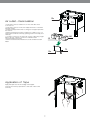
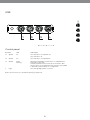
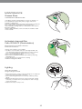
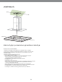
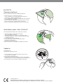
Island cooker hood
Saarekeliesituuletin
Apollon 900690IS 90 cm
Instruction manual
Käyttöohje
1
pg 2 - 10
s.
11 - 19
gned exclusively for domestic use to eliminate kitchen
ther than for which it has been designed.
der the hood when it is in operation.
it onto the bottom of the pan only, making sure that it
Apollon 900690IS 90 cm
sly monitored during use: overheated oil can burst into
d; risk of fire
GGESTIONS
Instruction manual
use by persons
Accordingly,
you may(including children) with reduced physilack of experience and knowledge, unless they have
cor
appliance.
on concerning use of the appliance by a person respon-
from incorrect or im-
nsure that they do not play with the appliance.
ctor hood ishot
650when
mm used with cooking appliances.”.
become
paragraphs on work-
ting plate fixed to the
from the mains supply before carrying out any mainte-
guarantees adequate
er
the specified time period (Fire hazard).
m diameter 125 mm.
and a neutral
liquid detergent.
RECOMMENDATIONS
AND SUGGESTIONS
ustion fumes (boilers,
•Read this instruction carefully before installation and use. Instructions in this manual must be followed the whole life cycle
of the equipment. The importer will not be held liable for any damages resulting from incorrect or improper installation,
misuse, accident, denting, changes made to the product or other abnormal use.
.g. gas burning applidicates
that
this
product
m in order to preventmay not be treated as household waste. Instead it shall be
INSTALLATION
cling of electrical
and electronic equipment. By ensuring this product is disposed of
•Never leave high naked flames under the hood when
ommunicating
directly
it is in operation.
nences
the for
cooker
hood
is
the•The
environment
and human
which between
could otherwise
caused
by
minimum
safetyhealth,
distance
the be
gas
cooker
•Adjust the flame intensity of the gas cooker top direct
top
and the extractor hood is 650 mm. When electric cooker electric, the
negative
only onto the bottom of the pan, making sure that it
ed information
about
recycling
of
this
product,
please
contact
your
local
city
office,
your
top isinto
used, the recommendation for the safety
distance is does not engulf the sides.
eing drawn back
mentioned later in this manual.
rchased the product.
•Deep fat fryers must be continuously monitored during use: overheated oil can burst into flames.
•Do not flambé under the range hood; risk of fire.
•This appliance is not intended for use by persons
(including children) with reduced physical, sensory or mental capabilities, or lack of experience and knowledge, unless
they have been given supervision or instruction concerning use of the appliance by a person responsible for their safety.
•CAUTION!: Accessible parts of the hood may become
hot by the heat of the stove!
•Check that the mains voltage corresponds to that indicated on the
rating plate fixed to the inside of the hood.
e manufacturer
or by
•Connect the extractor to the exhaust flue through a pipe
of minimum diameter 125 mm. The route of the flue must
be as short as possible.
•Do not connect the extractor hood to exhaust ducts carrying combustion fumes (boilers, fireplaces, etc.).
e to eliminate
kitchen
•If the extractor is used in conjunction with non-electrical
appliances (e.g. gas burning appliances), a sufficient
gned. degree of aeration must be guaranteed in the room in order to prevent the backflow of exhaust gas. The kitchen must
.
have an opening communicating directly with the open air y, making sure
that itto guarantee the entry of clean air. When the
in order
cooker hood is used in conjunction with appliances supplied with energy other than electric, the negative pressure in
ated oil can burst
into must not exceed 0,04 mbar to prevent fumes
the room
being drawn back into the room by the cooker hood.
•In the event of damage to the power cable, it must be
replaced by the importer or by the technical service
) with reduced
physi department,
in order to prevent any risks.
3
3
MAINTENANCE
•Switch off or unplug the appliance from the mains supply before carrying out any maintenance work.
•Clean and/or replace the Filters after the specified
time period (Fire hazard).
•Clean the hood using a damp cloth and a neutral
liquid detergent.
ge, unless they have
USE
by a person
respon-
•The extractor hood has been designed exclusively
appliance. for domestic use to eliminate kitchen smells.
•Never use the hood for purposes other than for which
ng appliances.”.
it has been designed.
rying out any mainte-
azard).
The symbol on the product or on its packaging indicates that this product may not be treated as household waste. Instead it shall be handed over
to the applicable collection point for the recycling of electrical and electronic equipment. By ensuring this product is disposed of correctly, you will help
prevent potential negative consequences for the environment and human health, which could otherwise be caused by inappropriate waste handling
of this product. For more detailed information about recycling of this product, please contact your local city office, your household waste disposal
service or the shop where you purchased the product.
sehold waste. Instead it shall be
uring this product is disposed of
h could otherwise be caused by
2
CHARACTERISTICS
Components
ACTERISTICS
Ref. Q.ty Product Components
1
1
2
1
2.1 1
2.2 1
3
1
3.1 1
3.2 1
9
1
10a 1 10b 1 14.1 1 15 1
16 1
25 Hood Canopy complete with: Controls, Light, Filters
Telescopic chimney, made up of:
Upper chimney
Lower chimney
Telescopic panel, made up of:
Upper panel
Lower panel
Reduction flange ø 150-120 mm
Dumper ø 150
Adapting ring ø 120-125 mm
Air Outlet Connector Extension
Air Outlet Connector
Tape
Hose clamps (not supplied)
Components
Product Components
Hood Canopy complete with: Controls, Light, Filters
Telescopic chimney, made up of:
Upper chimney
Lower chimney
Ref. Q.ty Installation Components
Telescopic panel, made up of:
7.3 1
Air outlet connector fixing bracket
1
Telescopic chimney fixing bracket
Upper7.2
panel
11 4
Wall plugs ø 10
12c 2 Screws 2.9 x 6.5
Lower12epanel
2
Screws 2.9 x 9.5
12f 4
Screws M4 x 80
Reduction
flange
ø 150-120
12g 4
Screws
M6 x 80 mm
12h 4 Screws 5.2 x 70
21 ø 150
1
Drilling template
Dumper
22 4
Washers ø 6.4
23 ring
4 ø Nuts
M6
Adapting
120-125
mm
Q.ty Documentation
Air Outlet
Connector
Extension
1
Instruction Manual
Air Outlet Connector
Novastick tape
Hose clamps (not supplied)
b
Installation Components
Air outlet connector fixing bracket
Telescopic chimney fixing bracket
Wall plugs ø 10
Screws 2.9 x 6.5
Screws 2.9 x 9.5
Screws M4 x 80
Screws M6 x 80
Screws 5.2 x 70
Drilling template
Washers ø 6.4
Nuts M6
Documentation
3
Dimensions
Dimensions
5
5
EN
4
INSTALLATION
Drilling the Ceiling/shelf and fixing the frame
ling the Ceiling/shelf and fixing the frame
DRILLING THE CEILING/SHELF
• Use a plumb line to mark the centre of the hob on the ceiling
support shelf.
• Place the drilling template 21 provided on the ceiling/support
shelf, making sure that the template is in the correct position
by lining up the axes of the template with those of the hob.
• Mark the centres of the holes in the template.
• Drill the holes at the points marked:
• For concrete ceilings, drill for plugs appropriate to the screw
size.
• For hollow brick ceilings with wall thickness of 20 mm: drill ø
10 mm(immediately insert the Dowels 11 supplied).
• For wooden beam ceilings, drill according to the wood
screws used.
• For wooden shelf, drill ø 7 mm.
• For the power supply cable feed, drill ø 10 mm.
• For the air outlet (Ducted Version), drill according to the
diameter of the external air exhaust duct connection.
• Insert two screws of the following type, crossing them and
leaving 4-5 mm from the ceiling:
• For concrete ceilings, use the appropriate plugs for the screw
size (not provided).
• for Cavity ceiling with inner space, with wall thickness of approx. 20 mm, Screws 12h, supplied.
• For wooden beam ceilings, use 4 wood screws (not provided).
• For wooden shelf, use 4 screws 12g with washers 22 and
nuts 23, provided.
DRILLING THE CEILING/SHELF
k the centre of the hob on the ceiling/support shelf.
ate 21 provided on the ceiling/support shelf, making sure that the
position by lining up the axes of the template with those of the hob.
oles in the template.
nts marked:
drill for plugs appropriate to the screw size.
ngs with wall thickness of 20 mm: drill ø 10 mm(immediately insert
d).
ngs, drill according to the wood screws used.
ø 7 mm.
5
able feed, drill ø 10 mm.
as above, making sure that you insert 2 of
panel lock;
sert the slots
the screws and slide them
Fixingonto
the Frame/Chimney
it be necessary
to adjust
the height of the frame, proceed
Fixing the
Frame/Chimney
ws:
screws
and insert the other two screws prosten the
metric
screws tojoining
the
two
opposite
parts that
Should
it be necessary
adjust the
height
of the
frame,
prceed as follows:
be seen from the front;
pic
chimney
remove
• Unfasten thelocking
metric screwsbracket
joining the two7.2,
opposite
parts
st the
height
the from
frame
as required,
then
replacethe
the
that can of
be seen
the front;
•
Adjust
the
height
of
the
frame
as
required,
then
replace
the
uble
sided
adhesive
and fixsure
it inside
frame
ws removed
as
above, making
that youthe
insert
2 of
screws removed as above, making sure that you insert 2 of
to the
panel lock;
close
tothem
the close
panel
lock;
ore
firmly.
• Lift the frame, insert the slots onto the screws and slide them
untilinsert
they lock;
the frame,
the slots onto the screws and slide them
• Tighten the two screws and insert the other two screws
they lock;
provided.
• Take the telescopic chimney locking bracket 7.2, remove the
two
screws
and
theandother
two
progtenofthethe
screws
itsided
isinsert
possible
make
film from
the double
adhesive
fix itto
inside
thescrews
frame small
so as to hold it more firmly.
d.frame, making sure that the screws do not
Before final locking
of the screws
it is possible
to make
the telescopic
chimney
locking
bracket
7.2,small
remove the
adjustments to the frame, making sure that the screws do not
ustment
slot.
come
out of the
adjustment
slot.
from the
double
sided
adhesive
and fix it inside the frame
be
securely
fastened
both
due
of
• The
Frame
must
be securely
fastened
bothto
duethe
to the weight
weight
to hold
it more
firmly.
on the Appliance
when in position.sideways
When fastened, prese stresspressure
caused
by occasional
check that the base is stable even when the Frame is
subjected
final locking
of
the
screws itWhen
is possible
to makecheck
small
ance
when
into bending.
position.
fastened,
• In all cases where the Ceiling is not sufficiently strong at
of suspension,
the Installation
technician
must
ments
thepoint
frame,
making
sure
that
screws do not
stableto the
even
when
the
Frame
isthesubjected
to
strengthen
it with suitable
plates
and counterplates,
of the Hood and the stress caused by occasional sideways
ut of theanchored
adjustment
slot. sound elements.
to structurally
Frame must be securely fastened both due to the weight of
e theand
Ceiling
is caused
not sufficiently
at presthe
Hood
the stress
by occasionalstrong
sideways
on the
when technician
in position. When
check
on,
theAppliance
Installation
mustfastened,
strengthen
the base is stable even when the Frame is subjected to
lates
and counterplates, anchored to structuring. nts.
l casesConnections
where the Ceiling is not sufficiently strong at the
DUCTED VERSION AIR EXHAUST SYSTEM
of suspension, the Installation technician must strengthen
When installing
ducted
version, connectanchored
the hood to the
th suitable
plates the
and
counterplates,
to structurchimney using rigid pipe ø 160 or 125 mm, the choice of which
is left to the installer.
sound elements.
Connections
flange 9 on the dumper 10a.
y using• reducer
rigid
ø 150ring
or10b.
125mm, the choice of which is
To
installpipe
the Adapting
• Fix the pipe in position using sufficient pipe clamps
he installer.
(not supplied).
• Remove any activated charcoal filters.
all
a
ø
150
mper 10a.
nstall the dumper 10a.
osition
sufficient
pipe pipe
clamps
(not
he pipe inusing
position
using sufficient
clamps
(notsupsup).
all a ø 125
nstall
a øair
125exhaust
mm air exhaust
connection,
insertthe
therere25
mm
connection,
insert
r flange 9 on the dumper 10a.
the dumper
10a.
nstall
the Adapting
ring 10b.
apting
10b. using sufficient pipe clamps (not suphe pipe ring
in position
).
osition
using sufficient pipe clamps (not supove any activated charcoal filters.
6
To install a ø 160
• To install AIR
the dumper
10a.
D VERSION
EXHAUST
SYSTEM
• Fix the pipe in position using sufficient pipe clamps
Connections
(not supplied).
e ducted
version, connect the hood to the
DUCTED
AIR EXHAUST SYSTEM
To install a VERSION
ø 125
pipe
ø
150
or
125mm,
the
choice
of which is
installing
the a ducted
version,
connectinsert
thethehood to the
• To install
ø 125 mm air
exhaust connection,
nsions 14.1 into the side of the Con
nto
the Support
bracket 7.3 and fix it
ulation
Version
into the
thepart
Cont14.1
7.3, fixing
it toside
the of
upper
with
Air outlet – Recirculation
Support
bracket
7.314.1
andisfix
it
ctor
extensions
outlet
in cormney openings both horizontally and
• Insert the Connector extensions 14.1 into the side of the
Connector 15.
• Insert the Connector 15 into the Support bracket 7.3 and fix it
with the screws.
• Fasten the Support bracket 7.3, fixing it to the upper part with
the Screws.
• Make sure that the Connector extensions outlet 14.1 is in correspondence with the Chimney openings both horizontally and
vertically.
• Join the Connector 15 to the Hood canopy outlet using a rigid
pipe ø 160 mm, selection of which is at the discretion
of the installation technician.
• Make sure that the Activated charcoal odour filter has been
fitted.
fixing it to the upper part with
the Hood canopy outlet using a rigid
m, selection of which is at the discrextensions outlet 14.1 is in corhnician.
openings
bothodour
horizontally
ated charcoal
filter hasand
been
od canopy outlet using a rigid
ction of which is at the discre.
harcoal odour filter has been
n of Novastick Tape
Tape of the Upper
e 16 Application
to the frontof edge
art down to the start of the Lower
Apply the tape 16 to the front edge of the Upper
Chimney from the top part down to the start of the Lower
Chimney.
ovastick Tape
o the front edge of the Upper
wn to the start of the Lower
7
Fitting the Panel and Fixing the Hood Canopy
efore fixing the Hood Canopy to the Frame:
Fitting the Panel
Remove the Grease filters from the Hood Canopy;
and Fixing the Hood Canopy
Remove any Activated charcoal filters.
Before fixing the Hood Canopy to the Frame:
Working
from
below,
theHood
Hood
canopy to the
• Remove
the Grease
filters fix
from the
Canopy;
• Remove any Activated charcoal filters.
Frame• Working
provided,
using
screws
from below,
fix thethe
Hood4canopy
to the 12f (M6 x 10)
Frame provided, using the 4 screws 12f (M6 x 10)
provided.
provided.
• Then hook the upper part of the Panel 3, adjusted to
size, to the rubber supports in the upper part and in
the lower part of the Frame.
• Slide the lower part of the Panel 3 until its metal tabs
slot into the slots in the frame;
Then hook the upper part of the Panel 3, adjusted to
size, to the rubber supports in the upper part and in
the lower
part of the Frame.
Slide the lower part of the Panel 3 until its metal tabs
slot into the slots in the frame;
ELECTRICAL CONNECTION
• Connect the plug to the socket. The plug must be accessible.
If used fixed connection, switch must be used. Switch must be
accessible.
• Remove the grease filters (see paragraph Maintenance)
being sure that the connector of the feeding
cable is correctly inserted in the socket placed on the
side of the fan.
ELECTRICAL CONNECTION
Connect the hood to the mains through a two-pole
switch having a contact gap of at least 3 mm.
Remove the grease filters (see paragraph Maintenance) being sure that the connector of the feeding
cable is correctly inserted in the socket placed on the
side of the fan.
8
USE
USE
Control panel
Control panel
BUTTON BUTTON
LED LED
T1 Speed
On
FUNCTIONS
FUNCTIONS
T1 Speed On Turns the Motor on at Speed one.
Turns the Motor off.
T2 Turns the Motor on at Speed two.
Speed On T3 Speed Fixed Flashing T2 Speed
On
T3 Speed
Fixed
L
Light L
Flashing
Turns the Motor on at Speed one.
Turns the Motor off.
When pressed briefly, turns the Motor on at Speed three.
Pressed for 2 Seconds.
Activates Speed four with a timer set to 10 minutes, after
which it returns to the speed that was set previously. Suitable
to deal with maximum levels of cooking fumes.
Turns the Motor on at Speed two.
When pressed briefly, turns the Motor on at Speed three.
Turns the Lighting System on and off.
Pressed for 2 Seconds.
Button T1 turns the motor off, after first passing to speed one.
Activates Speed four with a timer set to 10 minutes, af
which it returns to the speed that was set previously. Suita
to deal with maximum levels of cooking fumes.
Light
Turns the Lighting System on and off.
Warning: Button T1 turns the motor off, after first passing to speed one.
9
st
cleaned
every
monthsthem
of operation,
or
tersbeone
at a time
by 2pushing
towards the
y and
for pulling
particularly
usage,
and can be
up
down heavy
at the same
time.
hwasher.
s,
taking care not to bend them. Allow them to
ters one
at a time
by pushing them towards the
ting.
Grease
filters
up
pulling
down
the same
time. is visible
theand
filters,
make
sureat that
the handle
ETAL SELF- SUPPORTING GREASE FILTERS
s, taking
care not to bend them. Allow them to
MAINTENANCE
ting.
be cleaned
Greaseevery
filters 2 months of operation, or
the
make
sure
thatusage,
the handle
visible
CLEANING
METAL GREASE
FILTERS
forfilters,
particularly
heavy
and is
can
be
• The filters must be cleaned every 2 months of operation, or
washer.
more frequently for particularly heavy usage, and can be
a dishwasher.
rs onewashed
at ain time
by pushing them towards the
• Remove the filters one at a time by pushing them towards the
charcoal
filter
(Recirculation
version)
back of the group and pulling down at the same
time.
p and pulling
down
the
same
time.
• Wash the filters,
takingat
care
not to
bend them.
Allow them to
dry before refitting.
NG
THE
ACTIVATED
CHARCOAL
FILTER
taking
care
nottheto
bend
them.
them to
• When
refitting
filters,
make sure
that theAllow
handle is visible
on the outside.
ng.
t charcoal
washable
and cannot
be regenerated,
and must
filter
(Recirculation
version)
he filters, make
sure4that
the handle
is visibleor
pproximately
every
months
of operation,
NG THE ACTIVATED CHARCOAL FILTER
y for particularly heavy usage.
ttal
washable
and cannot be regenerated, and must
grease filters.
Activated
charcoal
filter
pproximately
every
4 months
or
turated
activated
carbon
filter of
by operation,
releasing the
Cello 2005ACF
y for particularly
heavy(Recirculation)
usage.
REPLACING THE ACTIVATED CHARCOAL
filters.into its seating.
ertalbygrease
hooking
FILTER CELLOit
charcoal
filter 2005ACF
(Recirculation version)
turated
activated
filter by releasing the
grease• Active
filters.
charcoal filtercarbon
is not included.
•
The
filter
is
not
washable
and
cannot
be regenerated,
G THE ACTIVATED
CHARCOAL
FILTER and
must be replaced approximately every 4 months of opera-
NCE
tion, or more frequently for particularly heavy usage.
• Remove
the it
metal
grease
filters.
er
by hooking
into
its
seating.
washable
and
cannot
be
regenerated, and must
• Remove the saturated activated carbon filter by releasing
fixing hooks.
grease• Fitthe
filters.
roximately
every 4 months of operation, or
the new filter by hooking it into its seating.
• Refit the metal grease filters.
for particularly
heavy usage.
al grease filters.
urated activated
carbon filter by releasing the
Lighting
Lighting
LIGHT REPLACEMENT
by hooking
it into its seating.
LIGHT REPLACEMENT
bulb type G4 20 W.
rease Halogen
filters.
Lighting
the snap-on lamp cover by levering it from under the
ht. • Remove
metal ring, supporting it with one hand.
• Remove
the halogen lamp from the lamp holder by pulling
LIGHT
REPLACEMENT
ap-on
lamp
gently. cover by levering it from under the
• Replace the lamp with a new one of the same type, making
portingsure
it with
hand.
that youone
insert the
two pins properly into the housings
on the lamp holder.
snap-on lamp
ht. • Replace
alogen
lampthefrom
thecover.
lamp holder by pulling
ap-on lamp cover by levering it from under the
porting
hand.
mp withit Lighting
awith
newone
one
of the same type, making
alogen
fromproperly
the lamp
holder
by pulling
nsert
thelamp
two pins
into
the housings
on
LIGHT
REPLACEMENT
r.
mp with
new one of the same type, making
ap-on
lampa cover.
nsert
t. the two pins properly into the housings on
r.
p-on lamp cover by levering it from under the
ap-on
cover.
orting lamp
it with
one hand.
ogen lamp from the lamp holder by pulling
10
1
11
to prevent any risks.
exclusively for domestic use to eliminate kitchen
an for which it has been designed.
hood when it is in operation.
o the bottom of the pan only, making sure that it
Apollon 900690IS 90 cm
nitored during use: overheated oil can burst into
of fire
ESTIONS
Käyttöohje
persons
gly,
you may(including children) with reduced physiknce.
of experience and knowledge, unless they have
cerning use of the appliance by a person respon-
orrect or im-
hat they do not play with the appliance.
d ishot
650when
mm used with cooking appliances.”.
me
phs on work-
e fixed to the
he mains supply before carrying out any mainte-
es adequate
specified
time period (Fire hazard).
ter 125 mm.
OHJEET JA SUOSITUKSET
neutral liquid detergent.
• Liesikuvun alla ei saa valmistaa liekitettäviä ruokia
tulipalovaaran vuoksi.
• HUOMIO! Lieden muodostama kuumuus saattaa kuumentaa
myös liesikuvun kosketettavissa olevat osat hyvin kuumiksi!
• Puhdista liesituuletin kostealla kankaalla ja miedolla, nestemäisellä pesuaineella.
Lue nämä ohjeet huolellisesti ennen asennusta ja käyttöä.
mes (boilers,
Asennus- ja käyttöohjeita on noudatettava koko laitteen käyttöiän. Maahantuoja ja takuu eivät kata sellaisia vaurioita jotka
aiheutuvat huolimattomasta tai väärästä asennuksesta, vääburning applirinkäytöstä,
onnettomuudesta,
kolhiintumisesta,
aterthis
product
may not be treated
as household waste.
Instead it shall be tuotteeseen
to prevent
tehdyistä muutoksista tai muusta tuotteen normaalista käyttöectricaldirectly
and tarkoituksesta
electronic equipment.
By ensuring this
product is disposed of
ating
poikkeavasta
käytöstä.
oker
hood is and human health, which could otherwise be caused by
the environment
the negative
ASENNUS
ation about recycling
of this product, please contact your local city
office, your
wn back into
SUODATTIMIEN VAIHTO
• Liesituulettimen suodattimista tulee aktiivisesti huolehtia
tässä ohjeessa jäljempänä määriteltyjen aikojen kuluessa.
Määritellyt vaihto- ja puhdistusajat ovat valmistajan
ohjeistuksia, eikä niitä saa ylittää.
• Todellinen vaihto- ja puhdistusaika riippuu aina käytöstä.
Käyttäjän velvollisuus on seurata suodattimien kuntoa
ja puhdistaa sekä vaihtaa suodattimet oikea-aikaisesti.
• Liesituulettimen rasvasuodatin tulee tarpeen mukaan
puhdistaa tulipalovaaran vuoksi.
• Aktiivihiilisuodatinta käytettäessä tulee aktiivihiilisuodatin
säännöllisesti vaihtaa, jotta laite ei vaurioidu ja että
puhallusteho säilyy ominaisuuksien mukaisena.
he product. • Asennus kaasutason päälle: Pienin sallittu turvaetäisyys
kaasulieden ja kuvun välillä on 650 mm.
acturer or •byAsennus sähkötason päälle: Valmistajan suositus lieden ja
kuvun etäisyydeksi on esitetty jäljempänä tässä ohjeessa.
• Tarkista, että käytettävän sähköverkon jännite vastaa liesi kuvun sisäpuolella olevaan arvokilpeen merkittyä jännitettä.
• Yhdistä liesituuletin hormiin mahdollisimman lyhyellä
putkella, jonka halkaisija on vähintään 125 mm.
inate kitchen
• Älä yhdistä liesituuletinta savuhormiin
(lämmityskattilat, tulisijat jne.).
• Mikäli liesituuletinta käytetään muiden kuin sähkölaitteiden
(esim. kaasuhella) yhteydessä, on huolehdittava työskenteriittävästä tuuletuksesta, etteivät poistettavat kaasut
g sure that itlytilan
pääse virtaamaan takaisin työskentelytilaan. Keittiössä on
oltava ilmanvaihtoaukko puhdasta tuloilmaa varten. Käyttö
an burst intotapahtuu oikein ja vaaratta, kun tilan enimmäispaine ei ylitä
arvoa 0,04 mBar.
• Jos virtajohto vahingoittuu, sen saa vaihtaa vain
maahantuoja tai tekninen huoltopalvelu.
3
3
HUOLTO
•
•
Sulje laite tai irrota sen pistoke pistorasiasta aina
ennen huoltoa.
Laitetta saa huoltaa ainoastaan maahantuojan
määrittämä huolto.
duced physiss they have
KÄYTTÖ JA VAROITUKSET
rson respon-
• Liesituuletin on tarkoitettu vain kotitalouskäyttöön.
• Laitetta eivät saa käyttää henkilöt (lapset mukaan lukien),
ce.
joiden psyykkinen, aistien tai mielen terveys on heikentynyt,
tai henkilöt, joilla ei ole tarpeellista kokemusta tai taitoa, ellei
ances.”.
heidän turvallisuudestaan vastaava henkilö ole valmentanut
heitä laitteen käyttöön tai valvo sitä.
• Valvo, etteivät lapset pääse leikkimään laitteella.
• Kaasutasoa käytettäessä säädä liekin teho siten, että
any mainte liekki kohdistuu vain astian pohjaan eikä sen reunoille.
• Friteerauskattiloita on paiston aikana valvottava, sillä
ylikuumentunut öljy voi leimahtaa tuleen.
. Instead it shall be
duct is disposed of
Symboli , joka on merkitty tuotteeseen tai sen pakkaukseen,
osoittaa, että tätä tuotetta ei saa käsitellä talousjätteenä.
Tuote on sen sijaan luovutettava sopivaan sähkö- ja elektroniikkalaitteiden kierrätyksestä huolehtivaan keräyspisteeseen.
Tämän tuotteen asianmukaisen hävittämisen varmistamisella
autetaan estämään sen mahdolliset ympäristöön ja terveyteen kohdistuvat haittavaikutukset, joita voi aiheutua muussa
tapauksessa tämän tuotteen epäasianmukaisesta jätekäsittelystä. Tarkempia tietoja tämän tuotteen kierrättämisestä saa
paikallisesta kunnantoimistosta, talousjätehuoltopalvelusta tai
liikkeestä, josta tuote on ostettu.
11
MITAT JA OSAT
Osat
Viite Lkm Tuotteen osat
1
1
Liesituulettimen runko, johon kuuluu: Kytkimet, valo,
suodattimet
2
1
Teleskooppihormi, jossa on:
2.1 1
Ylähormi
2.2 1
Alahormi
3
1
Teleskooppitpaneeli, johon kuuluu:
3.1 1
Yläpaneeli
3.2 1
Alapaneeli
9
1
Sovituslaippa ø 150-120 mm
10a 1 Venttiilillä varustettu laippa ø 150 mm
10b 1 Suurennusrengas ø 120-125 mm
14.1 1 Ilman ulostuloliitoksen jatke
15 1
Ilman ulostuloliitos
16 1
Teippi
25 Kiinnittimet (eivät kuulu toimitukseen)
RACTERISTICS
Components
y Product Components
Hood Canopy complete with: Controls, Light, Filters
Viite Lkm
Asennuksen
osatup of:
Telescopic
chimney,
made
7.3 chimney
1
Ilman ulostuloliitoksen kiinnitystuki
Upper
7.2 1
Teleskooppihormin kiinnitystuki
11 4
ø 10
Lower
chimneyRuuvitulpat
12c 2 Ruuvit 2,9 x 6,5
12e 2 Ruuvit 2,9 x 9,5
Telescopic
made
up of:
12f 4 panel,
Ruuvit
M4 x 80
12g 4 Ruuvit M6 x 80
Upper
12h panel
4
Ruuvit 5,2 x 70
21 1
Sapluuna
22 panel
4
Aluslaatat ø 6,4
Lower
23 4
Mutterit M6
Reduction
flange
ø 150-120 mm
Lkm Asiakirjat
Käyttöohjeet
Dumper
ø1 150
Adapting ring ø 120-125 mm
Air Outlet Connector Extension
Air Outlet Connector
Novastick tape
Hose clamps (not supplied)
b
y Installation Components
Air outlet connector fixing bracket
Telescopic chimney fixing bracket
Wall plugs ø 10
Screws 2.9 x 6.5
Screws 2.9 x 9.5
Screws M4 x 80
Screws M6 x 80
Screws 5.2 x 70
Drilling template
Washers ø 6.4
Nuts M6
y Documentation
Instruction Manual
12
Dimensions
Mitat
5
5
EN
13
ASENNUS
Katon/hyllyn poraaminen ja kehikon kiinnitys
ling the Ceiling/shelf and fixing the frame
KATON/HYLLYN PORAAMINEN
• Merkitse luotilangan avulla keittotason keskipiste kattoon/hyllyyn.
• Aseta kattoon/hyllyyn toimitettu liesituulettimen sapluuna 21 siten, että
keskipiste tulee kohdalleen ja että keittotason ja mallineen sivut ovat
samalla kohdalla.
• Merkitse sapluuna reikien keskipisteet.
• Poraa reiät seuraavalla tavalla:
• Massiivibetonikatto: käytettyjen betonimuuriankkurien mukaan.
• Tiilinen välikatto, kestävä paksuus 20 mm: ø 10 mm
(laita heti paikalleen toimitetut tulpat 11).
• Puupalkkikatto: käytettyjen puuruuvien mukaan.
• Puuhylly: ø 7 mm.
• Virtajohdon aukko: ø 10 mm.
• Ilman ulostulo (Imuversio): ulkopuolisen poistoputken halkaisijan mukaan.
• Ruuvaa kaksi ruuvia vastakkaisiin kulmiin ja jätä niiden kanta noin
4 -5mm:n etäisyydelle seinästä:
• Massiivibetoniin, betonimuuriankkurit, eivät kuulu toimitukseen.
• Tiiliseen välikattoon, kestävä paksuus noin 20 mm, toimitetut ruuvit 12h.
• Puupalkkikattoon, puuruuvit, eivät kuulu toimitukseen.
• Puuhyllyyn, toimitetut ruuvit 12g, välirenkaat 22 ja mutterit 23.
DRILLING THE CEILING/SHELF
k the centre of the hob on the ceiling/support shelf.
ate 21 provided on the ceiling/support shelf, making sure that the
position by lining up the axes of the template with those of the hob.
oles in the template.
nts marked:
drill for plugs appropriate to the screw size.
ngs with wall thickness of 20 mm: drill ø 10 mm(immediately insert
d).
ngs, drill according to the wood screws used.
ø 7 mm.
14
able feed, drill ø 10 mm.
as above, making sure that you insert 2 of
panel lock;
sert the slots
the screws and slide them
Fixingonto
the Frame/Chimney
it be necessary
to adjust the height
of the frame, proceed
Telineen/hormin
kiinnitys
ws:
screws
and insert the other two screws proJos telineen korkeutta halutaan säätää, se tehdään seuraavalla
sten the
metric screws joining the two opposite parts that
tavalla:
be seen•from
Ruuvaathe
auki front;
edessä näkyvät ruuvit, jotka yhdistävät kaksi
pic
chimney
locking
bracket
7.2,then
remove
etuosaa.
st the •height
of
the frame
as jarequired,
replacethe
the
Säädä teline halutulle
korkeudelle
ruuvaa irrottamasi
ruuvit
takaisin.
Muista
laittaa
2
ruuvia
paneeliryhmän
lähelle.
uble
sided
adhesive
and fixsure
it inside
frame
ws removed
as
above, making
that youthe
insert
2 of
• Nosta teline ylös, aseta reiät ruuveihin ja työnnä vasteeseen
saakka.
close
to
the panel lock;
ore
firmly.
• Kiristä kaksi ruuvia ja ruuvaa kiinni myös kaksi muuta toimitettua ruuvia.
the frame,
insert the slots onto the screws and slide them
• Ota teleskooppihormin kiinnitystuki 7.2, irrota tarranauhan
they lock;
kalvo ja kiinnitä se telineen sisäpuolelle pitämään sitä paikallaan.
twoscrews
screws and
the other
screws
progtenofthethe
it isinsert
possible
totwo
make
small
Ennen ruuvien lopullista kiristämistä on mahdollista tehdä
d.frame,
säätöjä
siirtämällä telinettä.
etteivät
ruuvit screws
irtoa säätöau- do not
making
sureVaro,that
the
kosta.
the telescopic
chimney locking bracket 7.2, remove the
ustment
slot.
• Teline
täytyy kiinnittää
tukevasti sekä
liesituulettimen
painonthe frame
from the
double
sided adhesive
and
fix it inside
että asennettuun laitteeseen mahdollisesti kohdistuvien sivukube
securely
ormitusten
to hold
it morefastened
firmly. both due to the weight of
vaikka
telineeseen kohdistuisi
taivutusrasitusta.sideways prese stress
caused
by occasional
• Mikäli katto ei ole kiinnityskohdassa riittävän tukeva, asentajan
täytyy
vahvistaa
sitä laatoilla
ja vastalaatoilla,
jotka
kiinnitetään
final locking
of
screws
itWhen
is possible
to makecheck
small
ance
when
in the
position.
fastened,
rakenteellisesti lujiin osiin.
ments
the frame,
making
that is
thesubjected
screws do not
stableto even
when
the sure
Frame
to
mukaan. Kun kiinnitys on tehty, varmista että pohja on vakaa,
ut of the adjustment slot.
Frame must be securely fastened both due to the weight of
e theand
Ceiling
is caused
not sufficiently
at presthe
Hood
the stress
by occasionalstrong
sideways
on the
when technician
in position. When
check
on,
theAppliance
Installation
mustfastened,
strengthen
Liitännät
the base
is stable even when the Frame is subjected to
lates
and
counterplates, anchored to structuring. POISTOKANAVALIITÄNTÄ
nts.
l casesImuversio
where asennetaan
the Ceiling
is liesituuletin
not sufficiently
strong at the
liittämällä
ilman ulostuloon
jäykällä putkella ø 160 tai 125 mm, asentajan valinnan mukaan.
of suspension, the Installation technician must strengthen
Putkiliitäntä
ø 160
th suitable
plates
and counterplates, anchored to structur• Laita laippa 10a, ø 150, liesituulettimen rungon ulostuloon.
sound elements.
Connections
aktiivihiilisuodattimet
y using• Molemmissa
rigidpoistaa.
pipetapauksissa
ø 150 ormahdolliset
125mm,
the choice of which is
täytyy
he installer.
all a ø10a.
150
mper
nstall the dumper 10a.
osition
sufficient
pipe pipe
clamps
(not
he pipe inusing
position
using sufficient
clamps
(notsupsup).
all a ø 125
nstall
a øair
125exhaust
mm air exhaust
connection,
insertthe
therere25
mm
connection,
insert
r flange 9 on the dumper 10a.
the dumper
10a.
nstall
the Adapting
ring 10b.
apting
10b. using sufficient pipe clamps (not suphe pipe ring
in position
).
osition
using sufficient pipe clamps (not supove any activated charcoal filters.
15
• Laita Suurennusrengas 10b, ø 120-125 mm
• Kiinnitä putki puristimilla 25
(eivät sisälly toimitukseen).
D VERSION
AIR EXHAUST SYSTEM
Putkiliitäntä ø 125
Connections
e ducted
version,
the hood
to the
•Jos käytät
putkea ø 125 connect
mm, laita kavennuslaippa
9
DUCTED
VERSION
AIR
asentamaasi
laippaan ø
160.EXHAUST SYSTEM
putki
puristimilla
25
pipe • øKiinnitä
150
ortoimitukseen).
125mm,
the choice of which is
installing
the
ducted
version, connect the hood to the
(eivät
sisälly
nsions 14.1 into the side of the Con
nto
the Support
bracket 7.3 and fix it
ulation
Version
into the
thepart
Cont14.1
7.3, fixing
it toside
the of
upper
with
Huoneilmaan palauttava
Support
bracket
7.314.1
andisfix
it
ctor
extensions
outlet
in cormney openings both horizontally and
• Työnnä liitoksen jatkeet 14.1 sivuilta liitokseen 15.
• Aseta liitos 15 tukeen 7.3 ja kiinnitä se ruuveilla.
• Kiinnitä tuki 7.3 ruuveilla yläosaan.
• Varmista, että liitoksen jatkeet 14.1 tulevat ulos hormin
aukkojen kohdalla sekä vaaka- että pystysuunnassa.
• Liitä liitos 15 liesituulettimen ulostuloon jäykällä putkella
ø 160 mm, jonka valitsee asentaja.
• Varmista, että aktiivihiilisuodatin Cello 2005ACF
on paikallaan.
fixing it to the upper part with
the Hood canopy outlet using a rigid
m, selection of which is at the discrextensions outlet 14.1 is in corhnician.
openings
bothodour
horizontally
ated charcoal
filter hasand
been
od canopy outlet using a rigid
ction of which is at the discre.
harcoal odour filter has been
n of Novastick Tape
e 16 Tarranauhan
to the front asennus
edge of the Upper
art down to the start of the Lower
Kiinnitä tarranauha 16 ylähormin etureunaan ylhäältä
alahormin alkuun saakka.
ovastick Tape
o the front edge of the Upper
wn to the start of the Lower
16
Fitting the Panel and Fixing the Hood Canopy
efore fixing the Hood Canopy to the Frame:
Paneelin asennus ja
Remove the Grease filters from the Hood Canopy;
liesituulettimen rungon
Remove any Activated charcoal filters.
kiinnittäminen
Working
from below, fix the Hood canopy to the
Ennen liesituulettimen rungon sijoittamista telineeseen:
Frame provided, using the 4 screws 12f (M6 x 10)
• Poista liesituulettimen rungosta rasvasuodattimet.
provided.
• Poista mahdolliset aktiivihiilisuodattimet.
• Kiinnitä sitten liesituulettimen runko alapuolelta
valmiiseen telineeseen 4 toimitetulla ruuvilla 12f
(M6 x 10).
Then hook the upper part of the Panel 3, adjusted to
sitten
paneelin
3 mittojen mukaan
size, •yläosa
toKiinnitä
the
rubber
supports
in thesäädetty
upper part and in
telineen ylä- ja alaosassa oleviin kumitukiin.
the lower
part of the Frame.
• Työnnä paneelin 3 alaosaa, kunnes sen kielekkeet
telineenpart
reikiin.of the Panel 3 until its metal tabs
Slide tarttuvat
the lower
slot into
the slots in the frame;
SÄHKÖLIITÄNTÄ
• Liitä tuulettimen pistotulppa pistorasiaan.
Pistotulppa tulee olla helposti luokse päästävissä. Jos
käytetään kiinteää asennusta pitää asennukseen liittää
katkaisija, joka on helposti luokse päästävissä.
• Poista rasvasuodattimet (katso kappaletta “Huolto”) ja
varmista, että virtajohdon liitin on kunnolla kiinni puhaltimessa.
ELECTRICAL CONNECTION
Connect the hood to the mains through a two-pole
switch having a contact gap of at least 3 mm.
Remove the grease filters (see paragraph Maintenance) being sure that the connector of the feeding
cable is correctly inserted in the socket placed on the
side of the fan.
17
KÄYTTÖ
USE
Control panel
Käyttöpaneeli
PAINIKE BUTTON
MERKKIVALO LED
T1 Speed
On
FUNCTIONS
TOIMINNOT
T1 Nopeus Palaa Käynnistää moottorin ensimmäisellä nopeudella.
Sammuttaa moottorin.
T2 Käynnistää moottorin toisella nopeudella.
Nopeus Palaa T3 Nopeus Kiinteä Vilkkuva T2 Speed
On
T3 Speed
Fixed
L
Valot L
Flashing
Turns the Motor on at Speed one.
Turns the Motor off.
Lyhyt painallus käynnistää moottorin kolmannella nopeudella.
Kun painiketta painetaan 2 sekunnin ajan.
Aktivoi neljännen nopeuden, joka toimii 10 minuuttia.
Ajastetun ajan päätyttyä nopeus palaa asetettuun arvoon.
Soveltuu käytettäväksi kun savua on paljon.
Turns the Motor on at Speed two.
When pressed briefly, turns the Motor on at Speed three.
Sytyttää ja sammuttaa valaistuksen.
Pressed for 2 Seconds.
Painike T1 sammuttaa moottorin. Puhallusteho laskee ennen liesituulettimen sammumista teholle yksi.
Activates Speed four with a timer set to 10 minutes, af
which it returns to the speed that was set previously. Suita
to deal with maximum levels of cooking fumes.
Light
Turns the Lighting System on and off.
Warning: Button T1 turns the motor off, after first passing to speed one.
18
st
cleaned
every
monthsthem
of operation,
or
tersbeone
at a time
by 2pushing
towards the
y and
for pulling
particularly
usage,
and can be
up
down heavy
at the same
time.
hwasher.
s,
taking care not to bend them. Allow them to
ters one
at a time
by pushing them towards the
ting.
Grease
filters
up
pulling
down
the same
time. is visible
theand
filters,
make
sureat that
the handle
ETAL SELF- SUPPORTING GREASE FILTERS
s, taking
care not to bend them. Allow them to
HUOLTO
ting.
be cleaned
every 2 months of operation, or
Rasvasuodattimet
the
make
sure
thatusage,
the
handle
visible
METALLISTEN
RASVASUODATTIMIEN
PUHDISTUS
forfilters,
particularly
heavy
and is
can
be
• Voidaan pestä myös astianpesukoneessa.
washer.
Pesu on tarpeen noin 2 kuukauden käytön jälkeen tai
useammin, jos laitetta käytetään paljon.
rs one• Irrota
at asuodattimet
time by
pushing them towards the
yksi kerrallaan työntämällä niitä taaksepäin
charcoal
filter
(Recirculation
version)
ja vetämällä samalla alaspäin.
p and pulling
downVältäatniiden
thetaivuttamista.
same time.
• Pese suodattimet.
Anna suodattimien kuivua ennen niiden paikalleen asettamista.
NG
THE
ACTIVATED
CHARCOAL
FILTER
taking
carenenot
to jabend
them.
Allow
them to
• Asenna
paikalleen
pidä kahva
näkyvissä
ulkopuolella.
ng.
t charcoal
washable filter
and cannot
be regenerated,
and must
(Recirculation
version)
he filters, make
sure4that
the handle
is visibleor
pproximately
every
months
of operation,
NG THE ACTIVATED CHARCOAL FILTER
y for particularly heavy usage.
Aktiivihiilisuodatin
Cello
2005ACFand must
ttal
washable
and cannot be
regenerated,
grease
filters.
AKTIIVIHIILISUODATTIMEN
2005ACF)
pproximately
everycarbon
4(CELLO
months
of
operation,
or
turated
activated
filter
byVAIHTO
releasing the
• Aktiivihiilisuodatinheavy
ei sisälly laitetoimitukseen
y for particularly
usage.
vaan on hankittava erikseen.
• Aktiivihiilisuodatinta ei voi pestä. Se vaihdetaan neljän
filters.
ertalbygrease
hooking
itväliajoin
intotai its
seating.
useimmin,
mikäli tuulettimen käyttö
charcoalkuukauden
filter
(Recirculation
version)
on erityisen runsasta.
turated
activated
carbon filter by releasing the
grease• Poista
filters.
metalliset rasvasuodattimet.
Poista keittiöhajujen kyllästämä
aktiivihiilisuodatin
G THE• ACTIVATED
CHARCOAL
FILTER
vetämällä sen hakasista.
NCE
• Asetaand
metalliset
rasvasuodattimet
uudelleen paikoilleen.
er
by hooking
it
into
its
washable
cannot
beseating.
regenerated,
and must
grease filters.
roximately
every 4 months of operation, or
for particularly heavy usage.
al grease filters.
uratedValaistus
activated
carbon filter by releasing the
Lighting
• Aseta uusi suodatin paikalleen.
LAMPUNVAIHTO
halogeenivalon tyyppi G4 20 W
LIGHT REPLACEMENT
by hooking
it into its seating.
• Poista metallinen lasisuojanpidin vetäen renkaan alta ja
samalla tukien sitä kädellä.
rease •filters.
Lighting
Irrota lamppu lampunpitimestä.
• Vaihda lamppu uuteen samanlaiseen. Huomioi pistokkeen
ht.
virheetön asennus sille tarkoitetulle paikalle lampunpitimessä.
LIGHT
• Aseta painettava
uudelleen paikoilleen.
ap-on lampREPLACEMENT
coverlasisuojanpidin
by levering
it from under the
porting it with one hand.
ht.
alogen
lamp from the lamp holder by pulling
ap-on lamp cover by levering it from under the
porting
hand.
mp withit Lighting
awith
newone
one
of the same type, making
alogen
fromproperly
the lamp
holder
by pulling
nsert
thelamp
two pins
into
the housings
on
LIGHT
REPLACEMENT
r.
mp with
new one of the same type, making
ap-on
lampa cover.
nsert
t. the two pins properly into the housings on
r.
p-on lamp cover by levering it from under the
ap-on
cover.
orting lamp
it with
onewww.cello-info.com
hand.
Manufactured for • Valmistuttaja • Tillverkad för • Produsert for • Изготовитель •Toodetud •
ogen lamp from
the pasūtītājs
lamp• Kieno
holder
pulling
Ražošanas
užsakymuby
pagaminta
• 19
Rautakesko Ltd., Finland. P.O. Box 75, FI-01301 VANTAA.
1
11