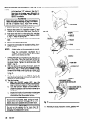
1
OWNER’S 820-047 MANUAL Rev. SUPERSEDES This manual contains Important Warnings and Instructions. Read the manual and keep it for reference. B A ‘2 T-6 PATENT NO. 4.397.610 PATENTED 1983 Canada Brevete 1964 FOREIGN PATENTS PENDING PAINT SPRAYER ULTIMATE NOVA”1000 AIRLESS 3yxx) psi (210 bar) MAXIMUM WORKING PRESSURE Model 820446, Series A Basic Sprayer, without hose, gun or spray tip Model 820-053 Includes Sprayer Model 820-045, hose, gun, selfclearing spray tip kit, and spray tip of choice. Index .2 Warnings .............................................. .4 Avertissement.. ...................................... .6 Advertencib ........................................... .8 Introduction .......................................... .9 Setup .................................................. .lO,ll Operation.. ...................................... .l 1 Shutdown and Care., ............................. .12 Flushing Guidelines.. .............................. .13 to 18 Troubleshooting.. .......................... .19 Repair Section Index. ............................. ..32 -34 Parts Lists Et Drawings., .................... How To Order Replacement .33 Parts .................................................. .Back Cover Technical Data.. ........................ J or fluids containing of explosion, which such solvents in this equipment Consult your fluid suppliers to ensure that the fluids being used are compatible with aluminum and zinc parts. The SHERWIN-WILLIAMS COMPANY, CLEVELAND, OHIO 44115 WARN/A/G HIGH PRESSURE SPRAY FOR PROFESSIONAL Read and understand FLU/D /NJECT/ON CAN CAUSE INJURY. USE ONLY. OBSERVE ALL WARNINGS. ail instruction manuals before operating equipment. ~j:‘Ji~&$.. ?~%i$dri :;irfTi;~lit~~;1~~li;.l:t:l~!.I:.ll,~;i~ilii!r8:~aiilj,:rtI~,~:~~;~~~~,~~~~~~,~,~~~~,f~~~kO~~~~~~~~:16:;,1~lifi: HAZARD General Safety This equipment generates very high fluid pressure. Spray from the gun, leaks or ruptured components can inject fluid through your skin and into your body and cause extremely serious bodily injury, including the need for amputation. Also, fluid injected or splashed into the eyes or on the skin can cause serious damage. NEVER point the spray gun at anyone or at any part of the body. NEVER put hand or fingers over the spray tip. NEVER try to “blow back” paint; this is NOT an air spray system. ALWAYS spraying. SERIOUS have the tip guard in place on the spray gun when ALWAYS follow the Pressure Relief Procedure, below, before cleaning or removing the spray tip or servicing any system equipment. Spray Gun Safety Devices Be sure all gun safety devices are operating properly before each use. Do not remove or modify any part of the gun; this can cause a malfunction and result in serious bodily injury. Safety Latch Whenever you stop the gun safety latch the gun inoperative. accidental triggering spraying, even for a moment, always set in the closed or “safe” position, making Failure to set the safety latch can result in of the gun. Diffuser The gun diffuser breaks up spray and reduces the risk of fluid injection when the tip is not installed. Check diffuser operation regularly. Follow the Pressure Relief Procedure, below, then remove the spray tip. Aim the gun into a metal pail, holding the gun firmly to the pail. Using the lowest possible pressure, trigger the gun. If the fluid emitted is not diffused into an irregular stream, replace the diffuser immediately. NEVER try to stop or deflect leaks with your hand or body. Be sure equipment before each use. Medical safety devices are operating Alert-Airless properly Spray Wounds lf any fluid appears to penetrate your skin, get EMERGENCY MEDICAL CARE AT ONCE. DO NOT TREAT AS A SIMPLE CUT. Tell the doctor exactly what fluid was injected. NOh to Physician: Injection in the skin is a traumatic in- jury. It is Important to treat the Injury surgically as soon as possible. Do not ddey treatment to research toxicity. Toxicity is a concern with some exotic coatings injected directly into the blood stream. Consultation with 8 plsstic surgeon or reconstructive hand surgeon may be edviseble. Tip Guard ALWAYS have the tip guard in place on the spray gun while soravina. The tie guard alerts YOUto the fluid iniection hazard and he@ reduce,-but does noi prevent, the risk-of accidentally placing your fingers or any part of your body close to the spray tip. Trigger Guard Always have the trigger guard in place on the gun when spraying to reduce the risk of accidentally triggering the gun if it is dropped or bumped. Spray Tip Safety Use extreme caution when cleaning or changing spray tips. If the spray tip clogs while spraying, engage the gun safety latch immediately. ALWAYS follow the Pressure Relief Procedure and then remove the spray tip to clean it. NEVER wipe off build-up around the spray tip until pressure is fully relieved and the gun safety latch is engaged. Pressure Relief Procedure To reduce the risk of serious bodily injury, including fluid injection, splashing fluid or solvent in the eyes or on the skin, or injury from moving parts or electric shock, always follow this procedure whenever you shut off the sprayer, when checking or servicing any part of the spray system, when installing, cleaning or changing spray tips, and whenever you stop spraying. (1) Engage the gun safety latch. (2) Turn the ON/OFF switch to OFF. (3) Unplug the power supply cord. (4) Disengage the gun safety latch. (5) Hold a metal part of the gun firmly to the side of a grounded metal pail, and trigger the gun to relieve pressure. (6) Engage the gun safety latch. (7) Open the pressure relief valve, having a container ready to catch the drainage. (8) Leave the pressure relief valve open until you are ready to spray again. lf you SUSp8Ct thet the spray tip or hose is completely clogged, or that pressure has not been fully relieved after following the steps 8bov8, VERY SLOWLY loosen the tip guard retaining nut or hose end coupling and relieve pressure gradually, then loosen tip or hose. UNPLUG CORD LATCH OPEN PRESSURE RELIEF VALVE FIRE OR EXPLOSION HAZARD ,.L : ; General Safety Any misuse of the spray equipment or accessories, such as overpressurizing, modifying parts, using incompatible chemicals and fluids, or using worn or damaged parts, can cause them to rupture and result in fluid injection, splashing in the eyes or on the skin, or other serious bodily injury, fire, explosion or property damage. NEVER alter or modify any part of this equipment; could cause it to malfunction. doing so CHECK all spray equipment regularly and repair or replace worn or damaged parts immediately. Always wear protective eyewear, gloves and clothing recommended by the fluid and solvent manufacturer. System as Pressure This sprayer can develop .5YZ23psi 1207 bar) MAXIMUM WORKING PRESSURE. Be sure that all spray equipment and accessories are rated to withstand the maximum working pressure of this sprayer. DO NOT exceed the maximum working pressure of any component or accessory used in the system. Fluid and Solvent Compatibility Always read the fluid and solvent manufacturer’s before using them in this sprayer. If you experience any static sparking or even a slight shock while using this equipment, STOP SPRAYING IMMEDIATELY. Check the entire system for proper grounding. Do not use the system again until the problem has been identified and corrected. Grounding To reduce the risk of static sparking, ground the sprayer and all other spray equipment used or located in the spray area. CHECK your local electrical code for detailed grounding instructions for your area and type of equipment. BE SURE to ground all of this spray equipment: literature High pressure fluid in the hoses can be very dangerous. If the hose develops a leak, split or rupture due to any kind of wear, damage or misuse, the high pressure spray emitted from it can cause a fluid injection injury or other serious bodily injury or property damage. ALL FLUID HOSES MUST HAVE SPRING GUARDS ON BOTH ENDS! The spring guards help protect the hose from kinks or bends at or close to the coupling which can result in hose rupture. TIGHTEN all fluid connections securely before each use. High pressure fluid can dislodge a loose coupling or allow high pressure spray to be emitted from the coupling. NEVER use a damaged hose. Before each use, check the entire hose for cuts, leaks, abrasion, bulging cover, or damage or movement of the hose couplings. If any of these conditions exist, replace the hose immediately. DO NOT try to recouple high pressure hose or mend it with tape or any other device. A repaired hose cannot contain the high pressure fluid. HANDLE AND ROUTE HOSES CAREFULLY. Do not pull on hoses to move equipment. Do not use fluids or solvents which are not compatible with the inner tube and cover of the hose. DO NOT expose Grace hose to temperatures above 1WF (82°C) or below -40°F (-46°C). Hose Grounding Static electricity is created by the high velocity flow of fluid through the pump and hose. If every part of the spray equipment is not properly grounded, sparking may occur, and the system may become hazardous. Sparking may also occur when plugging in or unplugging a power supply cord. Sparks can ignite fumes from solvents and the fluid being sprayed, dust particles and other flammable substances, whether you are spraying indoors or outdoors, and can cause a fire or explosion and serious bodily injury and property damage. Always plug the sprayer into an outlet at least 26 feet (6 ml away from the sprayer and the spray erea. Do not plug in or unplug any power supply cords in the spray area when there is any chance of igniting fumes still in the air. Continuity Proper hose grounding continuity is essential to maintaining a grounded spray system. Check the electrical resistance of your fluid hoses at least once a week. If your hose does not have a tag on it which specifies the maximum electrical resistance, contact the hose supplier or manufacturer for the maximum resistance limits. Use a resistance meter in the appropriate range for your hose to check the resistance. If the resistance exceeds the recommended limits, replace it immediately. An ungrounded or poorly grounded hose can make your system hazardous. Also read FIRE OR EXPLOSION HAZARD. 1. plug the power supply cord, or extension cord, each equipped with an undamaged three-prong plug, into a properly grounded outlet. Do not use an adapter. All extension cords must have three wires and be rated for 15 amps. 2. Fluid hoses: use only grounded hoses with a maximum of Sprayer: 560 feet (156 m) combined hose length to ensure grounding continuity. Refer to Hose Grounding Continuity. 3. Spray 4. Object being sprayed: 5. Fluid supply 6. All solvent pails used when flushing, according to local code. Use only metaf pails, which are conductive. Do not gun: obtain grounding through connection properly grounded fluid hose and sprayer. container: to a according to local code. according to local code. place the pail on a non-conductive surface, such as paper or cardboard, which interrupts the grounding continuity. 7. To maintain ingpressure, grounding continuity when flushing or reliev- always hold a metal part of the gun firmly to the side of a grounded metal pai!, then trigger the gun. Flushing Safety Reduce the risk of injection injury, static sparking, or splashing by following the specific flushing procedure given on page 12 of this manual. Follow the Pressure Relief Procedure on page 4, and remove the spray tip before flushing. Hold a metal part of the gun firmly to the side of a metal pail and use the lowest possible fluid pressure during flushing. Moving parts can pinch or amputate your fingers or other body parts. KEEP CLEAR of moving parts when starting or operating the sprayer. Unplug the sprayer, and follow the Pressure Relief Procedure on page 2, before checking or servicing any part of the sprayer to prevent it from starting accidentally. IMPORTANT United States Government safety standards have been adopted under the Occupational Safety and Health Act. These standards-particularly the General Standards, Part 1910, and the Construction Standards, Part 1926-should be consulted. 820447 3 AVERTISSEMENT La pulvkisation 4 haute pression peut causer des blessures tras graves. FMserv6 exclusivement B I’usage professionnel. Observer toutes les consignes de skurit6. Bien lire et bien comprendre tous les manuels d’instructions avant d’utiliser le materiel. R/SQ(JES D’/NJECT/ON Conslgnes ghhales .f“:<.. i:‘:;‘ \z ,;f” :3:,jj.:ji<j; y ,;);:>;,,: ,,;t,y; ‘;*:;: ,>;,.,r:;.tij ;;;;,‘i;‘;j’ de s6curlt6 Cet appareil produit un fluide B tr&s haute pression. Le fluide pulv&iz& par le pistolet ou le fluide sous pression provenant de fuites ou de ruptures peut pbnetrer sous la peau ou B I’intbrieur du corps et entrainer des blessures tr&s graves, voir m&me une amputation. M&me sans Btre sous pression, le fluide klaboussant ou entrant dans les yeux peut aussi entrainer des blessures graves. NE JAMAIS pointer le pistolet vers quelqu’un ou vers une partie quelconque du corps. NE JAMAIS mettre la main ou les doigts sur I’ajutage du pulv&isateur. NE JAMAIS essayer de “refouler” la peinture. Cet appareil N’est PAS un compresseur pneumatique. TOUJOURS garder la protection de I’ajutage en place sur le pistolet pendant la pulvkisation. TOUJOURS observer la March B Suivre pour D&endre la Pression donnk plus loin, avant de nettoyer ou d’enlever I’ajutage du pulv&isateur, ou d’effectuer un travail quelconque sur une partie de I’appareil. NE JAMAIS essayer d’arr&er ou de d&ier les fuites avec la main ou le corps. Avant chaque utilisetion, bien s’assurer que les dispositifs de &write fonctionnent correctement. Soins mbdlcaux En cas de pen&ration de fluide sous la peau: DEMANDER IMMEDIATEMENT DES SOINS MEDICAUX D’URGENCE. NE PAS SOIGNER CETTE BLESSURE COMME UNE SIMPLE COUPURE. Avis au medecln: La p&&ration est un traumatisme. II est chlrurglcalement cette des fluides sous la peau important de traiter blessure Immbdiatement. Ne pas retarder le traitement pour effectuer des recherches sur la toxicit& certains revetements exotiques sont dangereusement toxiques quend ils sont inject& directement dens le sang. II est souhaitable de consulter un chirurgien esth&ique ou un chirurgien spkialis6 dens la reconstruction des mains. Dlspositlfs de skurlt4 du pistolet Avant chaque utilisation, bien s’assure que tous les dispositifs de s&write du pistolet fonctionnent correctement. Ne pas Marche B Sulvre pour D&endre ; I;;:;;; ‘; enlever ni modifier une partie quelconque du pistolet; ceci risquerait d’entrainer un mauvais fonctionnement et des blessures graves. Verrou de s&wit& A chaque fois que I’on s’arrbte de pulv&iser, m&me s’il s’agit d’un court instant, toujours mettre le verrou de skuritb du pistolet sur la position “ferm6e” ou “skurite” (“safe”) pour empkher le pistolet de fonctionner. Si le verrou de s&write n’est pas mis, le pistolet peut se dklencher accidentellement. Voir la Fig. 3. Diffuser Le diffuseur du pistolet sert B diviser le jet et & reduire les risques d’injection accidentelle quand I’ajutage n’est pas en place. VBrifier le fonctionnement du diffuseur rtIguli&rement. Pour cette vkification, d&endre la pression en observant la Marche a Suivre pour DBtendre Ia-Pression donnk plus loin puis enlever I’ajutage du pulvkisateur. Pointer le pistolet dans un seau en m&al, en le maintenant fermement contre le seau. Puis, en utilisant la pression la plus faible possible, appuyer sur la gachette du pistolet. Si le fluide projet n’estpas diffuse sous forme de jet irrbulier, remplacer immbdiatement le diffuseur. Protection de l’ejuta e TOUJOURS maintenir f a protection de I’ajutage en place sur le pistolet du pulvksateur pendant la pulwkisation. La protection de I’ajutage attire I’attention sur les risques d’injection et contribue g reduire, mais n’Bvite pas le risque, que les doigts ou une partie quelconque du corps ne passent eccidentellement g proximitb immediate de I’ajutage du pulv6risateur. Consi nes de shurit6 pulvhr Bsateur concernant I’ajutage du Faire extrdmement attention B I’occasion du nettoyage ou du remplacement des ajutages du pulwkisateur. Si I’ajutage se bouche pendant la pulvksation, mettre immbdiatement le verrou de skuritb du pistolet. TOUJOURS bien observer la Marche B Suivre pour D&endre la Pression puis enlever I’ajutege du pulvkseteur pour le nettoyer. NE JAMAIS essuyer ce qui s’est accumulb autour de I’ajutage du pulvksateur avant que la pression ne soit compl&tement tomb& et que le verrou de skuritb du pistolet ne soit engagk la Pression Pour reduire les risques de blessures graves, y compris les blessures par injection de fluide ou celles causk par des Bclaboussures dans les yeux ou sur la peau, des pieces en mouvement ou par Electrocution, toujours bien observer cette march? B suivre B chaque fois que I’on arrke le pulv&isateur, & I’occasion de la verification ou de la reparation d’une pke de I’apparell de pulv&isation, g I’occasion de I’installation, du nettoyage ou du remplacement des ajutages et d’une man&e gbnkale g chaque arr&. 1) Engager le verrou de s&writ~ du pistolet. 2) Mettre I’interrupteur Marche-ArrBt sur ARRET (“OFF”). 3) Dbbrancher le cordon d’alimentation. 4) DBsengager le verrou de s&uritb du pistolet. 5) En maintenant une partie metallique du pistolet fermement appuy& contre le c&B d’un seau en m&al, appuyer sur la gachette du pistolet pour lib&er la pression. 61 Engager le verrou de skuritb du pistolet. 7) Ouvrir la soupape de &write en prenant soin d’avoir un recipient pr& g rkupbrer le liquide. 81 Laker la soupape ouverte jusqu’8 ce que le pulwkisateur soit de nouveau pr&t B &re utilisk Si l’on soupconne que l’ajutage du pulvksateur ment lib&e apr& 6 voir pro&de aux optkations ou le tuvau est compl&tement bouch8, ou que la pression n’a pas .4t6 compl&teci-dessus, desserrer TRES LENTEMENT I’Bcrou de retenue de la protection de I’ajutage ou le raccord du bout du tuyau et libker progressivement debaucher I’ajutage ou le tuyau. 1 4 820-047 2 3 la pression, puis terminer le desserrage. On peut maiAtenant 4.56 7 RISQUES Consignes EN CAS DE MAUVAISE g&&ales de s6curit6 UTILISATION Toute utilisation anormale de I’appareil de pulverisation ou des accessoires comme, par exemple, la mise sous une pression excessive, les modifications de pieces, I’utilisation de produits chimiques et de mati&es incompatibles et I’utilisation de pieces u&es ou abimk peut causer des d&&s a I’appareil ou des ruptures de pieces et entrainer une injection de liquide ou d’autres blessures serieuses, un incendie, une explosion ou d’autres d&&s. NE JAMAIS alterer ou modifier une piece de cet appareil; ceci risquerait d’entrainer son mauvais fonctionnement. VERIFIER regulierement tout I’appareil de pulverisation et ses kfuipements et reparer ou remplacer immediatement les pieces us&s ou abim6es. MESURES DE SECURITE CONCERNANT D’INCENDIE OU D’EXPLOSION,,;,,, De l’electricite statique est produite par le passage du fluide & grande vitesse dans la pompe et dans les tuyaux. Si toutes les pieces de I’appareil de pulkisation ne sont pas convenablement relik a la masse ou B la terre, des gtincelles peuvent se produire et I’appareil risque d’&re dangereux. Des etincelles peuvent Bgalement se produire B I’occasion du branchement ou du dbbranchement du cordon d’alimentation. Les Btincelles sont suffisantes pour allumer les vapeurs de solvants et le fluide pulverise, les fines particules de poussiere ainsi que d’autres substances inflammables, quand on pulv&ise 8 I’interieur ou a I’exterieur, et elles peuvent causer un incendie ou une explosion, ainsi qua des blessures graves et des d&&s materiels. Toujours brancher le pulverisateur dans une prise se trouvant a au moins 6 m (20 pieds) de I’appareil et de I’endroit oh se fait la pulverisation. Ne pas brancher ou debrancher un cordon d’alimentation quel qu’il soit dans la zone air se fait la pulverisation quand il y a le moindre risque que des vapeurs encore presentas dans I’air prennent feu. S’il se produit des Btincelles d’electricite statique, ou si vous ressentez la moindre decharae. ARRETU IMMEDIATEMENT LA PULVERISATION. VBrifik’que le systeme entier est bien mis a la terre. Ne vous servez pas du systeme avant que le probleme soit identifie et corrige. Mise B la terre ou B la masse :i -:.,I Compatibilit6 chimique Pour reduire les risques de production d’etincelles d’dlectricite statique, le pulverisateur et tous les &uipements utilises ou se trouvant dans la zone de pulverisation doivent Btre relit% a la terre ou B la masse. Pour connaitre le detail des instructions de mise B la terre dans la region et le type particulier d%quipement, CONSULTER le code ou les reglementations Blectriques locales. S’ASSURER qua tous les Bquipements de pulverisation suivants sont bien relies B la terre: 1. PuhGrisefeur: Brancher le cordon d’alimentation ou la rallonge qui doivent &re Bquipes d’une prise B 3 fiches en bon &at, dans une prise de courant convenablement mise a la terre. Ne pas utiliser d’adaptateur. Toutes les rallonges doivent avoir 3 fils et &re prevues pour 15 amperes. :;_ :, ” Ce oulverisateur oeut Droduire une PRESSION MAXIMUM DE TR;(VAIL 207 f&r l&W lb/PO?). S’assurer que tous les elements du pulverisateur et ses accessoires sont concus pour &sister a la pression maximum de travail de ce pulvtkisateur. NE PAS dbpasser la pression maximum de travail d’aucun des elements ou accessoires utilisk avec cet appareil. des corps BIEN S’ASSURER que tous les corps des solvants utilisk sont chimiquement compatibles avecles parties mouillees indiauk dans les “Donnk techniques”, au dos de la couvert&e. Toujours lire soigneusement les documents et brochures dir fabricant des fluides et solvants utilisk avant de s’en servir dans ce pulverisateur. LES TUyAU)( Le fluide B haute pression circulant dans les tuyaux peut 6tre tres dangereux. En cas de fuite sur le tuyau, de fissure, dkhirure ou rupture B la suite de I’usure, de d&&s ou dune mauvaise utilisation, les projections de fluide haute pression qui en proviennent peuvent entrainer des blessures graves par pen&ration sous la peau ou par contact, ainsi que des degllts materiels. TOUS LES TUYAUX FLEXIBLES DOIVENT AVOIR DES RESSORTS SPIRALE DE PROTECTION AUX 2 BOUTSI Les spirales de protection contribuent B Bviter la formation de pliures, de boucles ou de noeuds sur les tuyaux qui pourraient entrainer la rupture du tuyau B I’endroit du raccord ou B son voisinage. SERRER FERMEMENT tous les raccords avant chaque utilisation. Le fluide sous pression peut faire sauter un raccord desserre ou produire un jet B haute pression s’echappant par le raccord . NE JAMAIS utiliser un tuyau endommagk Avant chaque utilisation, verifier entierement chaque tuyau pour deceler les coupures, fuites, abrasions, boursouflures de I’enveloppe ou toute autre d&&ioration ou jeu des raccords. Si I’on constate I’une de ces deteriorations, il faut remplacer le tuyau immtkiiatement. NE PAS essayer de refaire le raccord d’un tuyau RlSQUES DU MATERIEL Pression FLEXIsLES is: ;>, I:’ .:,‘I ,; ‘,, j haute pression ni de reparer le tuyau avec du ruban adhkif ou par tout autre moyen. Un tuyau repare ne peut pas resister au fluide sous pression. MANIPULER LES TUYAUX AVEC PRECAUTION ET CHOISIR SOIGNEUSEMENT LEUR CHEMIN. Ne pas deplacer le fluide en tirant sur le tuyau. Ne pas utiliser de fluides ou de solvants aui ne sont oas comoatibles avec I’enveloppe interieure ou exterieure du tuyau: NE PAS exposer le iuyau B des temoeratures suoerieures a 82°C (180°F) ou infbrieures B -40°C (-;Qo’F). ’ Continuite de la mise B la terre des tu aux Une bonne continuite de la mise B la terre cres tuyaux est essentielle pour maintenir la mise B la terre de I’ensemble de vaporisation. Vdrifiez la resistance electrique de vos tuyaux B fluides et a air, au moins une fois par semaine. Si votre tuyau ne comporte pas d’kiquette qui prkise la resistance Blectrique maximum, prenez contact avec le fournisseur de tuyaux ou la fabricant pour avoir les limites de r&stance maximum. Utilisez un metre de r4sistence de la gamme approprib pour votre tuyau et vkifiez la r&stance. Si celle-ci depasse les limites recommandees, remplacez le tuyau immkiiatement. Un tuyau sans mise B la terre ou avec une mise B la terre incorrecte peut entraner des risques pour votre systbme. Lisez aussi LES RISQUES D’INCENDIE OU D’EXPLOSION ci-dessus. >. ‘;: i,;::;i::.-;:’ “.;::i ,’ ; ,: :,‘ : 2. Tuyaux flexibles: Afin d’assurer la continuite de la mise B la terre, n’utiliser que des tuyaux comportant une mise B la terre et ayant une longueur maximum combintk de 156 m (1566 pieds). Se reporter egalement au paragraphe “Continuit6 du circuit de mise B la terre des tuyeux”. 3. Pisfolef: RBaliser la mise B la terre en le raccordant a un tuyau flexible et a un pulverisateur deja convenablement relies B la terre. 4. Rhpient d’ahmentetion: observer le code ou les reglementations locales. 5. Objets, matkriel ou surfaces recevant la pulv&isation: observer le code ou les reglementations locales. 6. Tous /es seaux de solvents utilis& pour le rincage: observer le code ou les r&lementations locales. N’utiliser que des seaux m&a//iques conducteurs de I’electricite. Ne pas mettre le seau sur une surface non conductrice comme sur du papier ou du carton car cela interromprait la continuite le la mise a la terre. 7. Pour conserver la continuitd de la mise d /a terre quand on rince le mathriel ou quand on lib&e la pression, toujours maintenir une partie metallique du pistolet fermement appuyk contre le c&B d’un seau en m&al puis appuyer sur la detente du pistolet . Mesures de Sdcurit4 concernant le Rincage Pour reduire les risques de blessures par p&&ration de la peau et les risques dus aux Btincelles dWectricit6 statique ou aux Bclaboussures, observer la marche a suivre pour le rincage don&e B la page 12 de ce manuel. Observer ia “Marche~B Sulvre Dour DBtendre la Pression” donn& B la page 4 en enlever ?‘ajutaga du puhkisateur avant le rincage. ‘Maintenir une partie metallique du pistolet fermement appuyee contre le c&B d’un seau en m&a/ et utiliser la pression la plus faible possible pendant le rincage. 820447 5 AD VERTENCIA EL ROCIADO A ALTA PRESION PUEDE CAUSAR GRAVES LESIONES. SOLO PARA US0 PROFESIONAL. RESPETE LOS AVISOS DE ADVERTENCIA. Lea y entlenda todo el manual de instrucciones antes de manejar el equipo. PELiGRO DE /NYECC/ON Seguridad general DE FLU/DO ii4f~r~(i~t,~c:,;:,1,i.~~~~~::j.; i: .:,,>:: ; ‘,,:.il‘, : ~i;.;,<.;:;:~,;;,\. -;k;2;, $; ;rsL,i r;,,: Aparatos de seguridad de la pistoia puiverizadora Este equip0 genera un fluid0 a una presi6n muy alta. El rociado de la pistola, 10s escapes de fluid0 o roturas de 10s componentes pueden inyectar fluid0 en la piel y el cuerpo y causar lesiones extremadamente graves, incluyendo a veces la necesidad de amputaci6n. Tambien, el fluid0 inyectado o salpicado en 10s ojos puede causar graves daflos. NUNCA apuntar la pistola hacia alguien o alguna parte del cuerpo. NUNCA colocar la mano o 10s dedos encima de la boquilla. NUNCA tratar de “hater retornar la pintura”; este NO es un sistema de rociado de aire. SIEMPRE tener colocado el protector de la boquilla en la pistola mientras se esta pulverizando. SIEMPRE seguir el procedlmiento de descarga de presih, dado m&s abjo, antes de limpiar o sacar la boquilla o de dar servicio a cualiquier equip0 del sistema. NUNCA tratar de parar o desviar 10s escapes con la mano o el cuerpo . Asegurar que todos 10s aparatos de seguridad del equip0 est8n funcionando bien antes de cada uso. Tratamiento medico Si pareciera que un poco de fluid0 penetr6 la piel, conseguir TRATAMIENTO MEDICO DE URGENCIA DE INMEDIATO. NO TRATAR LA HERIDA COMO UN SIMPLE CORTE. Decir al medico exactamente cua fluid0 fue. A V/SO ai medico: Si se Jlega a inyectar este fluid0 an la piel Es Importante tratar une lesidn treum&ica. qulrQrglcamente la lesi6n a la brevedad posible. No se cause demorar et tretamiento pare investigar /a toxicided, La toxicided es e/go de sume imporfancia en elgunas pinturas exdtices cuendo se inyecten directemente al torrente senguinao. Sir6 conveniente consultar a un especielista en cirugfa pl&stica o reconstructive de las menos. Procedimiento de descarga Asegurar que todos 10s aparatos protectores de la pistola estan funcionando bien antes de cada uso. No sacar ni modificar ninguna pieza de la pistola pues podrla causar el malfuncionamiento de la misma con las consiguientes lesiones personales. kstillo de seguridad Cada vez que se deje de pulverizar, aunque sea por un breve momento, siempre colocar el pestillo de seguridad en la posici6n “cerrada”, lo que deja la pistola inoperante. El no hacerlo puede llevar al disparo imprevisto de la pistola. Difusor El difusor de la pistola dispersa el chorro pulverizado y reduce el riesgo de inyeccidn cuando no esta instalada la boquilla. Revisar con regularidad el funcionamiento del difusor. Seguir el procedimiento de descarga de presih, dado m6s abajo, y despu6s sacar la boquilla. Apuntar la pistola a un balde metalico, sosteniendola bien firma contra 61. Utilizando la presi6n m&s bajo posible, disparar la pistola. Si el fluid0 emitido no sale disperso en un chorro irregular, reemplazar de inmediato el difusor. Rotector de la boquilla SIEMPRE tener el protector de la boquilla colocado en la pistola mientras se esta pulverizando. Este protector llama la atenci6n contra el peligro de inyecci6n y ayuda a reducir, pero no evita, la colocaci6n accidental de 10s dedos o cualquier otra parte del cuerpo cerca de la boquilla. Seguridad de la boquiiia puiverizadora Tener mucho cuidado al limpiar o cambiar las boquillas. Si llegara a obstruirse mientras esta pulverizando, enganchar el pestillo de la pistola de inmediato. SIEMPRE seguir el procedlmlento de descarga de presih y despu6s sacar la boquilla para limpiarla. NUNCA limpiar la acumulacidn de pintura alrededor de la boquilla antes de que se haya descargado por complete la presi6n y el pestillo est6 enganchado. de presi6n Para reducir el riesgo de sufrir graves lesiones corporales, incluyendo inyecci6n o lesiones causadas por piezas en movimiento o choque ektrico, siempre seguir este procedimiento al apagar la maquina pulverizadora, al revisar o dar servicio a cualquier parte del sistema de pulverizaci6n, al instalar, limpiar o cambiar las boquillas, y cada vez que se deja de pulverizar. (11 Enganchar el pestillo de la pistola. (2) Mover el interruptor ektrico (ON/OFF) a la posici6n OFF (apagado). (3) Desenchufar el cord6n ektrico. (4) Desenganchar el pestillo de la pistola. (51 Sujetar una parte metalica de la pistola bien firme contra un balde de metal, y disparar la pistola para descargar la presi6n. (6) Enganchar el pestillo de la pistola. (7) Abrir la valvula de pr6sion y tener list0 un reclipiente para recibir la pintura. (8) Dejar la v6lvula de alivio de p&ion abierta hasta que se est4 nuevamente listo para pulverizar. Si se sospeche qua la boquila o la menguera estB completamente obstruida, o que no se ha descargado por complete la presidn despuk de heber seguido elprocedimiento anterior, aflojar MUY LENTAMENTE la tuerca de retenci6n del protector de la bo- quilla o acoplamiento de la punta de la manguera y descargar gradualmente la presi6n, despu& despejar la boquilla o la manguera. 1 6 820-047 2 3 %5,6 aflojarlo por complete. Luego, 7 PELIGRO POR MAL US0 DEL EQUlPO ” :i , PELIGRO DE INCENDIO 0 EXPLOSION Seguridad El flujo a alta velocidad del fluid0 al pasar por la bomba y manguera crea electricidad estatica. Si todas las partes del equip0 pulverizador no tienen buena tierra, pueden ocurrir chispas, convirtiendo al sistema en algo peligroso. Tambien, pueden producirse chispas al enchufar o desenchufar el cord6n ektrico. Estas chispas pueden inflamar 10s vapores de 10s solventes y el chorro de fluid0 pulverizado, particulas de polvo y otras sustancias inflamables, sea al aire libre o bajo techo, lo que podria causar una explosi6n o incendio y graves lesiones corporales y dahos a la propiedad. Enchufar siempre la pulverizadora a un tomacorriente que se encuentre a por lo menos 6 m (29 pies) de la maquina y del area que se va a rociar. No enchufar o desenchufar ningun corddn electrico en el lugar donde se esta rociando cuando todavia exista la posibilidad de que queden vapores inflamables en el aire. Si ocurre una chispa de electricidad estatica o incluso un ligero choaue electrico mientras se usa el equipo, DEJAR DE PULVERIZAR DE INMEDIATO. Revisar todo el sistema en busca de una tierra apropiada. No usar de nuevo el sistema hasta haber identificado y solucionado el problema. general Cualquier mal uso del equip0 pulverizador o 10s accesorios, tal coma sobrepresurizaci6n, modificaci6n de pie&, uso de materiales y productos quimicos incompatibles, o utilizacidn de piezas daAadas o desgastadas, puede hacen que se rompan y causen la inyecci6n de fluid0 u otras lesiones corporales graves, incendio, explosi6n o daflon a la propiedad. NUNCA alterar o modificar ninguna pieza de este equipo; el hacerlo podria causar una averia. REVISAR con regularidad el equip0 pulverizador y reparar o reemplazar de inmediato las piezas dafiadas o desgastadas. Presh del sistema Esta pulverizadora puede desarrollar 207 barias 0090 psi) de PRESION DE TRABAJO MAXIMA. Asegurar que todo el equip0 pulverizador y sus accesorios tienen la capacidad para aguantar la presi6n maxima de trabajo de esta pulverizadora. NO exceder la presi6n maxima de trabajo de ninglin componente o accesorio de este sistema. Compatibilidad de fluid0 ASEGURAR que todos 10s fluidos y solventes usados son qulmicamente compatibles con las piezas mojadas ilustradas en la hoja de datos tecnicos en la contratapa. Siempre leer las instrucciones del fabricante del fluid0 y solvente antes de usarlos en esta pulverizadora. SEGURlDAD EN EL US0 DE LAS MANGUERAS El fluid0 que escapa a alta presi6n por las mangueras puede ser muy peligroso. Si en la manguera se desarrolla un escape, una rotura o rajadura debido a cualquier tipo de desgaste, daflo o maltrato, el chorro a alta presi6n emitido por alli puede causar una lesi6n por inyecci6n u otras lesiones corporales graves o dafios a la propiedad. iTODAS LAS MANGUERAS PARA FLUIDOS TIENEN QUE TENER GUARDAS DE RESORTE EN AMBOS EXTREMOSl Estas protegen las mangueras contra dobleces o retorceduras en 10s acoplamientos o cerca de ellos, 10s que podrian traducirse en roturas de la manguera. Antes de usarlas, APRETAR bien firmes todas las conexiones. El fluid0 a alta presi6n puede desalojar un acoplamiento suelto o dejar que por 61 escape un chorro a alta presi6n. NUNCA usar una manguera que esta daflada. Siempre, revisarla en busca de cortaduras, escapes, abrasi6n, cubierta abultada, o acoplamientos sueltos o daflados. Si llegara a encontrarse cualquiera de estas condiciones, reemplazar de inmediato la manguera. NO intentar reacoplar una manguera de alta presi6n o enmendarla con cinta adhesiva u otro material similar. Una manguera que ha sido remendada no aguante el fluid0 a alta presi6n. MANEJAR Y PASAR CUIDADOSAMENTE LAS MANGUERAS. No tirar de las mangueras para mover el equipo. No war fluidos o solventes que Sean incompatibles con el tubo interno y la cubierta dela manguera. NO exponer las mangueras a temperaturas sobre 92’C (180°F) o bajo -40°C (-40°F). Continuidad manguera del circuit0 de puesta a tierra de la La continuidad del circuit0 de puesta a tierra apropiado es esencial para mantener conectado a tierra el sistema pulverizador. Es indispensable revisar la resistencia electrica maxima de las mangueras de aire y de fluid0 por lo menos una vez a la semana. Si la manguera no tiene una etiqueta en la cual se especifica la resistencia ektrica maxima, ponerse en contact0 con el proveedor o fabricante de la manguera para la informaci6n sobre 10s limites de resistencia. Usar un metro de resistencia en la gama apropiada para comprobar la resistencia; si excede 10s limites recomendados, reemplazarla de inmediato. Es muy arriesgado tener una manguera sin puesta a tierra o con la puesta a tierra en malas condiciones. Leer tambien la informaci6n sobre RIESGO DE INCENDIO 0 EXPLOSION, m&s arriba. Puesta a tierra Para reducir el riesgo de chispas estaticas, conectar a tierra la pulverizadora y todo el otro equip0 de pulverizar que se use o se encuentre en el lugar que se va a racier. CONSULTAR el cddioo electrico de la localidad para las instrucciones sobre las con&ones a tierra exigidas para la zone y tipo de equipo. ASEGURAR de conectar a tierra todo este equip0 pulverizador: 1. Pulverizadora: enchufar el cord6n ektrico, o cable extensor, cada uno con un enchuf de tres patas en buen estado, a un tomacorriente con puesta a tierra apropiado. No usar un adaptador. Totos 10s cables extensores tienen que tener tres hilos y una capacidad de 15 amperios. 2. Mangoeras pare fluidos: usar solamente mangueras con puesta a tierra de una longitud combinada de 159 m (500 pies), para asegurar buena continuidad a tierra. Referirse a tierra de la tambien al parrafo sobre continuidad manguera. 3. pistole: hater la puesta a tierra conectandola a una manguera de fluid0 y pulverizadora bien conectadas a tierra. 4. Suministrar un recipiente: de acuerdo al cddigo de la localidad. 5. Objet0 qoe se estB rociando: de conformidad con el c6digo local. 6. Todos /OS baldes de solvente usados durante el lavado, de conformidad con el cbdigo local. Usar solamente baldes de metal, que Sean conductivos. No colocar el balde en una superficie no conductiva, coma papel o catt6n, que interrumpe la continuidad a tierra. 7. Para mantener la continuidad a tierra durante et lavado o descarga de presihn, siempre apoyar una parte metalica de la pistola bien firme contra el costado del be/de de meta/, desputk apretar el gatillo. Seguridad durante el lavado Para reducir el riesgo de que se inyecte o salpique fluid0 en la piel, o que ocurra una descarga de electricidad estatica, siempre seguir las INSTRUCCIONES PARA EL LAVAOO, dadas en la pagina 12. Seguir el procedimlento de descarga de presih en la pagna 6, y quitar la boquilla rociadora antes de lavar. Apoyar una parte metalica de la pistola bien firme contra el costado de un be/de de metal y usar le presi6n m&s baja posible de fluid0 durante el lavado. PELlGRO DE LAS PtEZAS MOVILES Las piezas en movimiento pueden pinchar o amputar dedos u otras partes del cuerpo. MANTENERSE ALEJADO de las piezas en movimiento durante el arranque o funcionamiento de la pulverizadora. Desenchufar la pulverizadora y descargar la presi6n antes de revisar o dar servicio, a cualquier parte de pulverizadora, para impedir que arranque inesperadamente. IMPORTANT Se han adoptado las normas de seguridad del gobierno de 10s Estados Unidos de Norteamerica bajo el Acta de Seguridad y Salud Ocupacional. Deberan consultarse estas normas, en especial las Generales, Parte 1910, y las Normas de Construcci6n, Parte 1926. 820447 7 FLUID OUTLET CIRCUIT BREAKER RESET BUlTON ON/OFF SWITCH PAIL HANGER DISPLACEMENT PUMP PRESSURE RELIEF VALVE MAIN FLUID HOSE WHIP HOBE Your new Ultimate NovaTM 1000 Sprayer functions and operates differently than other airless paint sprayers. This section will help you become familiar with the sprayer before operating it. Pressure Control The pressure control includes an ON/OFF switch for the sprayer, the pressure adjusting control knob, a pressure sensing device, and a current overload circuit breaker with a manual reset button. Its function is to control the motor speed so that the sprayer maintains constant fluid pressure at the pump outlet. Motor The DC motor has sealed bearings and replaceable motor brushes. Its function is to drive the displacement pump at the rate needed to supply sufficient paint volume at the selected pressure. Working together, the pressure control and motor cause the pump to cycle whenever there is fluid or pressure demand. When the pump is cycling, the motor sounds like an automobile starter cranking. When the pump is not cycling, the motor hums, hums intermittently, or appears to have shut itself off. However, there will still be power to the sprayer and it will stay pressurized and ready to use unless you manually shut it off and relieve pressure. Because the motor is DC, it is less sensitive to low voltage or voltage fluctuations than an AC motor, and a heavy gauge extension cord of up to 150 feet (45 ml can be used. Drive Assembly The sealed drive assembly transfers power from the DC motor to the displacement pump. 8 820-047 Displacement Pump The positive displacement, volume-balanced pump provides equal fluid delivery on both the up and down pump strokes. The pump has a wet-cup which, when filled with Grace Throat Seal Liquid, helps prevent damage to the throat packings and piston rod. Hoses The grounded, nylon spray hoses have spring guards on both ends. The 50 foot (15.2 ml hose has a l/4 in. ID. The 3 foot (0.9 ml, 3/16 in. ID whip hose allows flexible gun movement. The nylon hose material acts as a pulsation dampener to absorb pressure fluctuations. Spray Gun 8 Reverse-A-Clean@ Ill Spray Tip The high pressure spray gun has a trigger safety which prevents accidental triggering when it is engaged (see below). The Reverse-A-Clean Ill spray tip uses high pressure fluid to remove clogs from the spray tip without removing it from the gun. It includes a safety tip guard which helps reduce the risk of injection injury. SAFETY LATCH SHOWN ENGAGED Reverse-A-Clean” Ill is a registered tradename of Grace Inc. Connect Hose and Gun Remove the plastic plug from the pressure control outlet nipple. Connect the main fluid hose to the fluid outlet of the pressure control. See Fig 1. Connect the shorter hose to the main hose and then connect a spray gun to the other end of the hose. Don’t use thread sealant, and don’t install the spray tip yet! WARNING If you are supplying your own hoses and spray gun, be sure they are electrically grounded and rated for at least m psi (210 b8r) Working Pressure and that the gun has a tip guard. This is to reduce the risk of serious bodly injury caused by static sparking, fluid injection or overpressurizing and rupturing the equipment. For two gun hookup, remove the plastic cap plug from the l/4 npsm(f 1 nipple and connect an accessory hose and spray gun. See Fig 1. CAUTION Fig 1 To avoid damaging the pressure control, which may result in poor equipment performance and component damage, follow these precautions: 1. Always use at least 50 ft (15 ml of nylon spray hose. 2. Never use a wire braid hose as it is too rigid to act as a pulsation dampener. 3. Never install any shutoff device between the fluid outlet of the pressure control and the first 50 ft (15 m) of spray hose. 4. Always use the main fluid outlet for one-gun operation. Never plug this outlet. Fill Packing Nut/Wet Cup Pour throat seal liquid, supplied with the sprayer, into the packing nut/wet-cup until it is l/3 full. Keep the wet-cup filled to help protect and prolong the life of the pump throat packings. See Fig 2. SECONDARY Fig 2 Check Electrical Service Be sure the electrical service is 126 V, 60 HzAc, 15 amp (minimum) and that the outlet you use is properly grounded. Use an extension cord which has 3 wires of minimum 12 gauge size, rated for 15 Amps, and a maximum of 150 ft (45 m) long. Longer lengths may affect sprayer performance. Plug In Sprayer Be sure the ON/OFF switch is OFF. Plug the power supply cord into a grounded elec:rical outlet that is at least 26 ft (6 m) away from the spray area to reduce the chance of a spark igniting the spray vapors. See Fig 3. Do not remove the third prong of the power supply cord plug, which is the grounding prong, and do not use an adapter. Flush the Pump Flush the pump to remove the lightweight oil which was left in to protect pump parts after factory testing. Refer to page 12 for WHEN and HOW to flush. Fig 3 Prepare the Paint Prepare the paint according to the manufacturer’s recommendations. Remove any skin that may have formed, and stir the paint to dissolve hard pigments. Strain the paint through a fine nylon mesh bag (available at most paint dealers) to remove particles that could clog the spray tip. This is probably the most important step toward trouble-free spray painting. 820447 9 NOTE: -ARNING To reduce the risk of serious bodily injury, including fluid injection, splashing fluid or solvent in the eyes or on the skin, or injury from moving parts or electric shock, always follow this procedure whenever you shut off the sprayer, when checking or servicing any part of the spray system, when installing, cleaning or changing spray tips, and whenever you stop spraying. 1. 2. 3. 4. 5. Engage the gun safety latch. Turn the ON/OFF switch to OFF. Unplug the power supply cord. Disengage the gun safety latch. Hold a metal part of the gun flrmly to the side of a grounded metal pail, and trigger the gun to relieve pressure. 6. Engage the gun safety latch. 7. Open the pressure relief valve, having a container ready to catch th drainage. 8. Leave the pressure relief valve open until you are ready to spray again. If YOU SUSp8Ct th8t th8 Spray tip Or hose is COmpte t8iy clogged, or the t pressure h8s not been f&y refi8ved after following the steps above, VERY SLOWLY loosen the tip guard retaining nut or hose end coupling and relieve pressure gradually, then loosen completely. Now clear the tip or hose. riming the Sprayer lose the pressure relief valve. If a secondary hose and gun is not installed, be sure the cap is securely plugging the nipple. See Fig 2. Plug in the sprayer. Don’t install the spray tip in the gun yetl Place the suction tube into the paint container. Turn the pressure control knob all the way counterclockwise to the lowest pressure setting. See Fig 3. Disengage the gun safety latch. MAINTAIN FIRM METAL TO METAL CONTACT BETWEEN GUN AND CONTAINER If the paint is hard to prime, place a waste container under the pressure relief valve and open it. When fluid comes from the valve, close it. Then disengage the gun safety latch and follow the paragraph above. Check all fluid connections for leaks. If any are found, follow the Pressure Relief Procedure Warning, above, before tightening connections. Install the Spray Tip and Tip Guard Be sure the gun safety latch is engaged. Install the tip and tip guard as instructed in the separate gun or tip instruction manual. Adjusting the Spray Pattern Increase the pressure adjusting knob setting just until spray from the gun is completely atomized. Refer to Fig 3. To avoid excessive overspray and fogging, and to decrease tip wear and extend the life of the sprayer, always use the lowest possible pressure needed to get the desired results. If more coverage is needed, use a larger tip rather than increasing the pressure. Test the spray pattern. To adjust the direction of the spray pattern, engage the gun safety latch and loosen the retaining nut. Position the tip so the groove is horizontal for a horizontal pattern or vertical for a vertical pattern. Then tighten the retaining nut. Operating Tips These suggestions will help prevent the motor from running too hot or operating intermittently. ODecrease the pressure when using a small tip. l Keep the sprayer in a shaded area when spraying outdoors. l Turn off the sprayer and relieve pressure whenever you stop spraying. Cleaning a Clogged Tip IARNING To reduce the risk of serious bodily injury from fluid injection, use extreme caution when clean or changing spray tips. DO NOT hold your hand, body, or a rag in front of the spray tip when cleaning or checking a clogged tip. Always point the gun toward the ground or into a pail when checking to see if the tip is clear. Never wipe off buildup around the spray tip until pressure is fully relieved and the gun safety latch is engaged. DO NOT try to “blow back” paint; this is NOT an I air spray sprayer. Fig 4 Hold a metal part of the gun firmly against the side of a grounded metal pail, and trigger the gun into the pail. Hold the trigger open, turn the sprayer ON, and slowly increase the pressure setting until the sprayer starts. Refer to Fig 4. This procedure reduces the risk of static electric discharge and splashing. Keep the gun triggered until all air is forced out of the system, and the paint flows freely from the gun. Release the trigger and engage the gun safety latch. 10 820-047 Follow the instructions given in your separate gun or spray tip instruction manual for cleaning a spray tip. SHUTDOWN AND CARE Check the packing nut/wet-cup daily. First follow the Pressure Relief Procedure Warning on page 10. Keep the wet-cup l/3 full of throat seal liquid at all times to help prevent fluid buildup on the piston rod and premature packing wear. The packing nut should be tight enough to stop leakage, but no tighter. Overtightening may cause binding and excessive packing wear. Use a screwdriver and light hammer to adjust the nut. See Fig 5. Flush the sprayer at the end of each work day and fill it with mineral spirits to help prevent pump corrosion and freezing. See “Flushing Guidelines” on’page 12. CAUTION Never leave water or any type of paint in the sprayer over night to: (1) prevent pump corrosion; (21 to prevent the fluid from freezing in the pump and pressure control which can cause loss of pressure, stalling or serious sprayer damage. Always use mineral spirits for the final flush. Relieve pressure. This leaves a protective coating of mineral spirits in the pump. For very short shutoff periods, leave the suction tube in the paint, follow the Pressure Relief Procedure Warning, page 10, and clean the spray tip. Coil the hose and hang it on the hose rack when storing the sprayer, even for overnight, to help protect the hose from kinking, abrasion, coupling damage, or other damage. Fig 5 CAUTION When adjusting the packing nut, be careful not to nick the cylinder threads which may be protruding above the bearing housing. Nicks to these threads may strip the threads in the bearing housing when the displacement pump is removed or installed. 820-047 11 When to Flush 1. New Sprayer. Your new Ultimate NovaTM 1000 Sprayer was factory tested in lightweight oil which was left in to protect pump parts. Before using water-base paint, flush with mineral spirits, followed by soapy water, and then a clean water flush. Before using oil-base paint, flush with mineral spirits only. 2. Changing Colors. Flush with a compatible solvent such as mineral spirits or water. to oil-base paint. 3. Changing from water-base Flush with soapy water, then mineral spirits. paint. 4. Changing from oil-base to water-base Flush with mineral spirits, followed by soapy water, then a clean water flush. How to Flush 1. Engage the gun safety latch, turn the ON/OFF switch to OFF, release the gun safety, trigger the gun to relieve pressure, engage the gun safety and open the pressure relief valve. 2. Pour one-half gallon (2 liters) of compatible solvent into a bare metal pail. Put the suction tube in the pail. 3. Close the pressure relief valve. 4. Remove the spray tip from the gun. 5. Point the spray gun into a metal waste container and with a metal part of the gun firmly touching the metal container, squeeze the gun trigger. See Fig 6. Thls procedure helps reduce the risk of static sparking and splashing. With the gun triggered, turn the ON/OFF switch to ON and slowly turn the pressure adjusting knob clockwise lust unNI the sprayer starts. Keep the gun triggered until clean solvent comes from the nozzle. Release the trigger and engage the gun safety latch. 6. Check all fluid connections for leaks. If any leak, first follow the Pressure Relief Procedure Warning on page 10. Now tighten the connections, start the sprayer, and recheck the connections for leaks. 7. Remove the suction tube from the pail. Disengage the gun safety and trigger the gun to force solvent from the hose. Do not let We pump run dry for more than 30 seconds to avoid damaging the pump packings! Then turn ON/OFF switch to OFF and engage the gun safety. 12 620-047 Storage. Water-base paint: flush with water, then mineral spirits and leave the pump, hose and gun filled with mineral spirits. Shut off and unplug the sprayer, open the pressure relief valve to relieve pressure and leave open. Oil-base paint: flush with mineral spirits. Shut off and unplug the sprayer, open the pressure relief valve to relieve pressure and leave open. 6. Startup after storage. Before using water-base paint, flush out mineral spirits with soapy water and then a clean water flush. When using okbase paint, flush out the mineral spirits with the fluid to be sprayed and the sprayer is ready to use. 5. MAINTAIN FIRM METALTO METAL CONTACT BETWEEN GUN AND CONTAINER WHEN RELIEVING PRESSURE AND Fig 6 8. Unplug the power supply cord. Open the pressure relief valve and leave open until you are ready to use the sprayer again. 9. If you flushed with mineral spirits and are going to use a water-base paint, flush with soapy water followed by a clean water flush. Then repeat Step 1. TROUBLESHOOTiNG GUIDE ;z’r:f$.:,;:::,,: ;f, ,i,:” :; :I-‘; >‘.< i ;1 _ ,; i ;‘:, ii 5 WARNING Pressure Relief Procedure To reduce the risk of serious bodily injury, including fluid injection, splashing fluid in the eyes or on the skin, or injury from moving parts or electric shock, always follow this procedure whenever you shut off the sprayer, when checking or servicing any part of the spray system, when installing, cleaning or changing spray tips, and whenever you stop spraying. 1. Engage the gun safety latch. 2. Turn the ON/OFF switch to OFF. 3. Unplug the power supply cord. 4. Disengage the gun safety latch. 5. Hold a metal part of the gun firmly to the side of a metal pail, and trigger the gun to relieve pressure. 6. Engage the gun safety latch. 7. Open the drain valve. 8. Leave the drain valve open until you are ready to spray again. If you suspect that the spray tip or hose is completely clogged, or that pressure has not been fully relieved after following the steps above, VERY SLOWLY loosen the tip guard retaining nut or hose end coupling and relieve pressure gradually, then loosen completely. YPE OF PROBLEM IOTOR WON’T Now clear the tip or hose. WHAT TO CHECK If check is OK, go to next check WHAT TO DO When check is not OK refer to this columr I OPERATE asic Fluid Pressure Problems lasic Mechanical Problems I. Check the pressure control knob setting. The motor will not run if it is at the minimum setting (fully counterclockwise). I. Slowly increase the pressure setting to see if the motor starts. 2. Check for a clogged spray tip. Refer to your separate gun or tip instruction manual. 2. Relieve pressure, refer to your separate gun or tip instruction manual for tip cleaning. 1. Check for frozen or hardened fluid in the pump (39) and/or pressure control bourdon tube. Using a screwdriver, carefully try to 1. Thaw’. Plug in sprayer and turn on. Slowly increase pressure setting to see if motor starts. If it doesn’t, replace the displacement pump packings (see manual 307-793) and/or rotate fan at back of motor by hand. See page 22. replace the bare pressure control box (301P. See page 26. 2. Push pin into place and secure with the 2. Check displacement pump connecting rod spring retainer. pin L?CH.It must be completely pushed into connecting rod l29) and spring retainer (35) should be firmly in groove of connecting rod, Sea page 28. basic Electrical Problems 3. Check for motor damage. Remove drive housing assembly (18). Try to rotate fan by hand. See page 29 2. Replace motor (1) if fan won’t turn. 1. Check sprayer circuit breaker (303) button to be sure it has not popped up. 1. Depress circuit breaker button to reset. If circuit breaker continues to open, see “Electrical Short”, page 18. 2. Check electrical supply with volt meter. Meter should read 105 to 125 VAC. 2. Reset building circuit breaker; replace building fuse. Try another electrical outlet. 3. Check extension cord for visible damage. Use a volt meter or test lamp at extension cord outlet to check. 3. Replace extension cord. 4. Check sprayer power supply cord (311) for visible damage such as broken insulation or wires. 4. Replace power supply cord. See page 23. 5. Check motor brush leads, terminals and brush length. Brush length should be l/2” minimum. See page 22. 5. Tighten terminal screws; replace brushes. Sea page 22. ‘Thaw the sprayer if water or water-based fluid has frozen in it, due to exposure to low temperatures, by placing it in a warm area. Do not try to start the sprayer until it has thawed completely. If the bourdon tube was not damaged by the freezing, the pump should operate. If fluid hardened (dried) in the sprayer, the pump packings and/or bare pressure control must be replaced. See page 26 or manual 307-793. When replacing the bare pressure control box (item 3011, remove the circuit breaker, ON/OFF switch, bridge, circuit board and electrical hardware and reinstall these parts in the bare box. Troubleshooting continued on next page. 820447 13 WHAT TO CHECK TYPE OF PROBLEM MOTOR WON’T If check is OK, to to next check WHAT TO DO When check is not OK refer to thii column OPERATE Diagnosing circuit board indicator lamps. The normal condition is red lamp on, clear lamp on when boerd is 1. Check leads from bridge 13081to motor to be 1. Replace any loose terminals and crimp to leads. Be sure male terminal blades are sure they are securely fastened and properly straight and firmly connected to mating part. mated. telling pump 2. Check Gl and G2 connections between circuit board (23) and bridge 008) for damage or loose terminals. 2. Clean circuit board male terminals. Replace loose or damaged terminals. Securely reconnect leads. 3. Check for loose motor brush lead connections and terminals. See page 22. 3. Tighten terminal screws. Rapl8Cebrushes if leads are damaged. See page 22. 4. Check brush length which should be l/2” minimum. See page 22. NOTE: Brushes do not wear at the same rate on both sides of motor. 4. Replace brushes. See page 22. 5. Check for broken or misaligned motor brush springs. Rolled portion of spring must rest squarely on top of brush. See page 22. 5. Replace spring if broken. Realign spring with brush. See page 22. 6. Check motor brushes for binding in brush holders. Sea page 22. 6. Clean brush holders. Remove carbon with small cleaning brush. Align brush lead with slot in brush holder to assure free vertical brush movement. 7. Check motor armature commutator for burn spots, gouges and extreme roughness. Remove motor cover and brush inspection plates to check. See page 22. 7. Remove motor and have motor shop resurface commutator if possible. See page 36. 8. Check motor armature for shorts using armature tester (growler) or perform spin test. See page 19 8. Replace motor. See page 36. 9. Check bridge (3!38) by substituting with a good bridge or performing bridge test. See page 20. CAUTION: Do not perform this check until armature is determined to be good. A bad armature will immediately burn out a good bridge. 9. Replace bridge. See page 24. 1. Check circuit breaker 069) button to be sure it has not popped up. 1. Depress circuit breaker button to reset. If cir cuit breaker continues to open, see “Electrical Short”, 18. 2. Check sprayer power supply cord (311). Disconnect TP6 female end TPl female and connect volt meter to these leads. Plug in sprayer. Meter should read 105 to 125 VAC. Unplug sprayer. Reconnect TPl. 2. Replace power supply cord. See page 23. to run. Follow Pressure Relief Procedure. Remove gun from hose. Remove pressure control cover and check for faulty condition of circuit board lamps. Condition A both lamps on; pump won’t operate and motor is not running Condition B Both lamps off 3. Check ON/OFF switch 003). Disconnect TP2 3. Replace ON/OFF switch. See page 23. and connect volt meter to TP6 female and TP2 male. Plug in sprayer and turn on. Meter should read 105 to 125 VAC. Turn off and unplug sprayer. Reconnect TP2. Troubleshooting 14 820-047 continued 4. Check jumper wire KIO6). Disconnect TP3 and connect volt meter to TP6 female and TP3 female. Plug in sprayer and turn on. Meter should read 105 to 125 VAC. Turn off and unplug sprayer. Reconnect TP3. 4. Replace jumper wire. See page 24. 5. Check circuit breaker 009). Connect volt meter to TP6 female and TP4. Plug in sprayer and turn on. Meter should read 105 to 125 VAC. Turn off and unplug sprayer. 5. Replace circuit breaker. See page 24. on nextpege. YPE OF PROBLEM ondition B Iontinued) :ondition C led lamp on, clear lamp off lnplug spra yerl WHAT TO DO WHAT TO CHECK When check is not OK refer to this column If check is OK, go to next check 6. Check motor thermal cutout switch. Connect volt meter to TP6 female and TP9 female. Plug in and turn on sprayer. Meter should reed 105 to 125 VAC. Turn off and unplug sprayer. 6. Allow motor to cool. Correct cause of overheating. If switch remains open after motor cools, check continuity between TP9 female and TPlO with ohmmeter. If open, replace motor. 7. Check microswitch (301). Reconnect TP6 connectors. Connect volt meter to TP15 male and TP4. Meter should read 50-125 VAC. 7. Clean microswitch male terminals. Replace loose or damaged terminals. Securely reconnect leads. 8. Visually inspect microswitch (302) button. Adjustment stud (Q) should not depress the microswitch button when fluid pressure is zero. Manually check by depressing button with small screwdriver; an audible click indicetes microswitch is in normal position. 8. Microswitch repair. is faulty. Return sprayer for 9. Check meter. should in the 9. Microswitch repair. is faulty. Return sprayer for microswitch (302) continuity with ohm Meter read zero ohms with no fluid pressure sprayer. Be sure sprayer is unplugged! lO.Check all terminals for damage or loose fit. Reconnect TP6 connectors. 10. Replace damaged terminals and reconnect securely. 11 .Check circuit board (23) by substituting a good board. See page 25. 11.Replace circuit board. See page 25. with 1. Check circuit board (23) by removing from box without disconnecting wires; see page 25 for removal procedure. 1. Replace circuit board. See page 25. WARNING: Removing the circuit board while still wired over-rides the optical detector which could cause the sprayer to overpressurize, if the microswitch does not function properly. Turn the sprayer on ONLY long enough to check lamp condition, then shut off immediately. WARNING: To reduce the risk of electric shock, handle board by edges only1 Do not allow any metal objects to come in contact with the board! Plug in and turn on sprayer. Clear lamp should be on now - removing the circuit board over-rides the optical detector. Turn off and unplug sprayer. 2. Check bourdon tube flag and detector position. Reinstall circuit board (see page 25). Turn pressure setting to maximum; flag should extend less than half way into optical detector slot from the bottom. 2. Calibrate pressure control to see if that corrects problem. See page 27. If not, replace bare pressure control box WlP. See page 26. OPTICAL DETECTOR CIRCUIT BOARD VIEW OF OPTICAL DETECTOR AND FLAG ‘When replacing the bare preeeure control box 1301), remove the circuit breeker,bridge, circuit board and electrical hardware and reinetell in the new bare box. Troubleshooting continued on next pege. 820447 16 WHAT TO DO WHAT TO CHECK TYPE OF PROBLEM When check is not OK refer to this column If check is OK, go to next check LOW OUTPUT I. Check for worn spray tip. I. Follow Pressure Relief Procedure then replace tip. See your separate gun or tip manual. !. Check to see that pump does not continue to stroke when gun trigger is released. Plug in and turn on sprayer. Prime with fluid. Trigger gun momentarily, then release and engage safety latch. Relieve pressure, turn off and unplug sprayer. 2. Service pump. See manual 307-793. 3. Check electrical supply with volt meter. Meter should read 105 to 125 VAC. 3. Reset building circuit breaker; replace building fuse. Repair electrical outlet or try another outlet. 0. Check extension cord size and length; must be at least 12 gauge wire and no longer than 150 ft (15.2 ml. 1. Replace with a correct, grounded extension cord. 5. Check Gl and G2 leads from bridge 009) to circuit board (23) for damage or loose wires or connectors. Refer to page 25. 5. Clean circuit board male terminals. Replace loose or defective lead terminals. Securely reconnect lead terminals to board. 5. Check stall pressure. Refer to Calibration Procedure on page 27. 5. Calibrate pressure control. See page 27. 7. Check bridge W9) + and - leads and terminals to motor. Inspect wiring insulation and terminals for signs of overheating. See page 24. 7. Be sure male terminal blades are centered and firmly connected to female terminals. Replace any loose terminal or damaged wiring. Securely reconnect wires to bridge. 3. Check for loose motor brush leads and terminals. See page 22. 3. Tighten terminal screws. Replace brushes if leads are damaged. See page 25. 3. Replace brushes. See page 22. 3. Check for worn motor brushes which should be l/2” minimum. See page 22. lO.Check for broken and misaligned motor brush springs. Rolled portion of spring must rest squarely on top of brush. lO.Replace spring if broken. Realign spring with brush. See page 22. 11.Check motor brushes for binding in brush holders. See page 22. 11.Clean brush holders, remove carbon dust with small cleaning brush. Align brush lead with slot in brush holder to assure free vertical brush movement. 12.Check circuit board (23) by substituting a good circuit board. See page 22. 12.Replace circuit board. See page 22. with 13.Check motor armature for shorts by using an armature tester (growler) or perform spin test. See page 19. 13.Replace motor. See page 31. 14.Check bridge UO9) by substituting with a good bridge or by performing the bridge test. See page 24 or 20. CAUTION: Do not perform this check until armature is determined to be good. A bad armature will immediately burn out a good bridge. 14.Replace bridge. See page 24. 1. Check fluid supply. 1. Refill and reprime pump. 2. pk 2. Remove and clean, then reinstall. NO OUTPUT Motor runs and pump strokes for clogged intake strainer. See page 3. Check for loose suction tube or fittings. See page 29. Troubleshooting 16 820-047 continued on next page. 3. Tighten; use thread sealant or sealing tape on threads if necessary. YPE OF PROBLEM WHAT TO DO WHAT TO CHECK When check is not OK refer to this column If check is OK, go to next check1 10 OUTPUT Continued) Aotor runs but pump does ot stroke 4. Check to see if intake velve ball and piston ball are seating properly. See manual 307-793. 4. Remove intake valve and clean. Check balls and seats for nicks; replace if necessary. See manual 307-783. 5. Check for leaking around throat packing nut which may indicate worn or damaged packings. See manual 307-793. 5. Replace packings. See manual 307-793. Also check piston valve seat for hardened fluid or nicks and replace if necessary. 1. Check displacement pump connecting rod pin. See page 28. 1. Replace pin if missing. Be sure retainer spring is fully in groove all around connecting rod. See 28. 2. Check connecting rod assembly for damage. See page 28. 2. Replace connecting rod assembly. See page 28. 3. Be sure crank in drive housing rotates; plug in sprayer and turn on momentarily to check. Turn off and unplug sprayer. See page 28 3. Check drive housing assembly for damage and replace if necessary. See page 28 1. Be sure both Gl and G2 leads from bridge (308) to circuit board (23) are firmly connected. See page 25. 1. Reconnect securely. See page 24 and 25. 2. Check stall pressure. Refer to Calibration procedure on page 27. 2. Calibrate pressure control See page 27. 3. Check bourdon tube flag and detector position. Turn pressure setting to maximum; flag should not drag or bind in optical detector slot of circuit board. 3. Carefully bend flag into alignment with detector slot to see if that corrects problem. If not, replace bare pressure control assembly (361 I*. Calibrate pressure control after reassembly. iXCESSlVE PRESSURE ‘LUCTUATIONS ipray pattern variations. CIRCUIT BOARD OPTICAL DETECTOR FLAG VIEW OF OPTICAL DETECTOR AND FLAG 4. Check circuit board (23) by substituting a good board. See page 25. with 4. Replace circuit board. See page 25. 5. Check LOW OUTPUT section on page 16. dOTOR IS HOT 6 WNS INTERMllTENTLY 1. Check to see if sprayer has been o erating at 1. Decrease pressure setting or increase tip size. high pressure with small tips., whrc3 causes low motor RPM and results tn excessive heat build up. 2. Check to see if ambient temperature where sprayer is located is more than 9ooF KKX) or if sprayer is located in direct sun. 2. roo$biprayer to shaded, cooler area if 3. Check to see if sprayer has been left in a stalled condition (sprayer turned on, pressurized,. but not operating) for long periods of time. 3. Turn off sprayer whenever you stop spraying for a while and relieve fluid pressure. ‘When replacing the bare pressure control box (301), remove the circuit board, bridge, circuit board, and electrical hardware and reinstall in the new bare box. Troubleshooting continued on next pege. 820447 17 I TYPE OF PROBLEM WHAT TO CHECK I I ELECTRICAL SHORT Building circuit breaker opens as soon as sprayer switch is turned on. CAUTION If check is OK, go to next check When check is not OK refer to this column I I I 1. Check all electrical wiring for damaged insulation, and all terminals for loose fit or damage. Be sure to check wires between pressure control and motor which are encased in conduit (22). See page 29. 1. Repair or replace any damaged wiring or terminals. Securely reconnect all wires. Any short in any part of the motor power circuit, which is 2. Check for missing inspection plate gasket 2. Correct faulty conditions. connected to the output side (see page 221, bent terminal forks or other of the bridge, will cause the metal to metal contact points which could bridge to burn out immediatecause a short. ly. Correctly diagnose and repair all shorts before check- 3. Check motor armature for shorts by using an 3. Replace motor. See page 30. ing and replacing bridge. armature tester (growler) or perform spin test. See page 19. Inspect windings for burns. 4. Check bridge 009) by substituting with a good bridge or by performing bridge test. See page 20. 4. Replace bridge. See page 24. CAUTION: Do not perform this check until armature is determined to be good. A bad armature will immediately burn out a good bridge. Building circuit breaker opens 1. Check ‘Basic Electrical Problems’ on page 14. as soon as sprayer is plugged 2. Replace ON/OFF switch. See page 23. into outlet and sprayer is NOT 2. Check ON/OFF switch BO3) See page 23. Be sure the sprayer is unplugged! Disconnect turned on. wires from switch and check switch with ohm meter. The ohm meter should read infinity with the ON/OFF switch OFF, and zero with the switch ON. CAUTION: A short in the motor circuit will burn the bridge out immediately, which in turn usually causes the ON/OFF switch to fail in the closed mode. Sprayer circuit breaker opens after sprayer operates for only 5 to 10 minutes. 1. Check electrical supply with volt meter. Meter should read 105 to 125 VAC. 1. If voltage is too high, do not operate sprayer until corrected. 2. Check tightness of pump packing nut. Overtightening nut tightens packings on rod, restricts pump action, and damages packings. See page 29. 2. Loosen packing nut. Check for leaking around throat. Replace pump packings, if necessary. See manual 397-793. 3. Check stall pressure. Remove the elbow (88) and secondary ball valve KU from the tee (124) at the pressure control outlet. Install a 5000 psi (350 bar) fluid-filled pressure gauge in the tee (124). See page 27. Plug in and turn on sprayer. Slowly increase pressure setting to maximum. Pump should stall at 2800-3000 psi (196-210 bar). Turn off and unplug sprayer. 4. After determining that there is no short in system, reset circuit breaker button. Calibrate pressure control. See page 27. 4. If circuit breaker continues to open (button ;:;I ;J), replace the circuit breaker. Sea I 18 820047 Before doing this procedure, follow the Pressure Relief Procedure Warning on page 13 to reduce the risk of an injection injury, injury from moving For checking armature, motor winding and brush electrical continuity. setup Remove the drive housing from the sprayer as described in “Drive Housing Replacement”, Steps l-6, page 29. Remove the pressure control cover and screws, the motor cover, the fan cover (FI, and the inspection covers (J). See Fig 7. Disconnect the two leads from the motor to the bridge KICW. See Fig 8 and 9. Armature Short Circuit Test Quickly turn the motor fan by hand. lf there are no shorts, the motor will coast two or three revolutions before coming to a complete stop. If the motor does not spin freely and resists rotation, the armature is shorted and the motor must be replaced. See page 36. Armature, Brushes, and Motor Wiring Open Circuit Test (Continuity) Connect the two black motor leads together with a test lead. Turn the motor fan by hand at about two revolutions per second. If there is uneven or no turning resistance, check the following: a1 broken brush springs; b) broken brush leads; c) loose brush terminal screws; d) worn brushes; e) broken motor leads; f) loose motor lead terminals. Repair parts as needed. See page 22. If there is still uneven or no turning resistance, replace the motor. See page 30. Fig 7 23 308 Fig 8 820-047 19 BRIDGE WIRES Remove the bridge from the pressure control box and perform this test to determine if the bridge is functional. Use a continuity tester, such as multi-meter set on the Xl ohms scale ( Q 1. Eight individual checks, or tests, must be performed. If the bridge fails even one test, it must be replaced. Fig 9 shows the position of the wires on the bridge. Using the chart at the right, connect the meter wires as indicated by the black dots for each test, then check the continuity. TEST 1 TEST 2 TEST 3 In Tests 1, 2 and 3, there should be NO continuity. In Tests 4.5 and 6, connect the + and - meter wires as indicated, check continuity, then switch the meter wire connections and check continuity again. You should get NO continuity one way, and YES continuity the other way. In Tests 7 and 8, connect the meter wires as indicated by the black dots. Touch the indicated “G” wire to one meter wire, and then to the other. You should get NO continuity one way, and YES continuity the other way. TEST 4 TEST 5 NO\1 t I/rc.I 1 TEST 6 TEST 7 ------ Fig 9 20 826-647 z -or 3 TEST 8 :: REPAIR SECTION INDEX Procedure Page General Repair Notes.. ..................................... ..2 1 Motor Brush Replacement ................................. ..22 Power Supply Cord Replacement .......................... ON/OFF Switch Replacement.. ............................ $z Bridge Rectifier Replacement ............................... ;: Circuit Breaker Replacement ................................ Circuit Board Replacement.. ............................... .25 Pressure Control Replacement ............................ ‘26 Stall Pressure Calibration .................................. ..2 7 Bearing Housing 8 Connecting Rod Replacement .... .28 Drive Housing Replacement ................................. . Motor Replacement.. ....................................... ..36 Parts Drawing 8 List, Sprayer.. ............................ . Parts Drawing 8 List, Pressure Control ................... . How To Order Replacement Parts.. ...................... .33 NOTE: See separate manual 307-793 for displacement pump repair. GENERAL REPAIR NOTES “Y I; i The following tools are needed when repairing this sprayer. Phillips screwdriver Small flatblade screwdriver Needle nose pliers Plastic mallet Adjustable wrench 2” adjustable, open-end wrench Torque wrench l/4” hex key wrench 3116” hex key wrench 5/8” socket wrench 318” open end wrench l/2” open end wrench 314” open end wrench 7/8” open end wrench High quality motor oil Bearing grease For calibration 4. 1. When disconnecting wires in the pressure control assembly, use needle nose pliers to separate mating connectors. When reconnecting the wires, be sure the flat blade of the insulated male connector is centered in the wrap-around blade of the female connector when the connection is made. Route wires in the pressure control assembly carefully through the legs of the U-shaped bourdon tube, where appropriate, to avoid interfering with the bourdon tube which moves as the pressure setting changes and to avoid pinching the wires between the pressure control box and cover. CAUTION Improper wire routing can result in poor sprayer performance or damage to the pressure control. Keep all screws, nuts, washers, gaskets, and electrical fittings removed during repair procedures. These parts are not normally provided with replacement assemblies. Test your repair before regular operation of the sprayer to be sure the problem is corrected. If the sprayer does not operate properly, review the repair procedure again to verify that everything was done correctly. If necessary, refer to the Troubleshooting Guide to help identify other possible problems and solutions. WARNING To avoid serious bodily injury, including electric shock, DO NOT touch any moving parts or electrical parts with your fingers or a tool while inspecting the repair. Shut off the sprayer and unplug it as soon as you complete the inspection. Reinstall all covers, gaskets, screws and washers before operating the sprayer. wire could loosen the connector from the wire. 3. only: “:- I ;‘, Before repairing any part of the sprayer, read the following general repair notes and the repair procedure. Be sure you have the necessary tools and parts available. 2. procedure 3/8” ianition wrench 0.015”spray tip High pressure, oil-filled test gauge, Part No. 820-455 5 gallon pail Clean water Mineral spirits NEW 3ooo psi (210 bar) high pressure spray hose CAUTION Do not run the sprayer dry for more than 36 seconds to avoid damaging the pump packings. 5. Reinstall the motor cover before regular operation of the sprayer and replace it if it is damaged. The cover directs cooling air around the motor to help prevent overheating. It can also help prevent burns, fire or explosion; see the WARNING, below. WARNING During operation, the motor becomes very hot and could burn your skin if touched. Flammable fluids and materials spilled on the hot, bare motor could cause a fire or explosion. Always have the motor cover in place during regular operation to reduce the risk of burns. fire or exolosion. 820-047 21 NOTE: Replace the brushes when they have worn to no less than l/2” minimum. See Fig 11. Note that the brushes wear differently on each side of the motor. Brush Repair Kit 620-521 is available. Before doing this procedure, follow the Pressure Relief Procedure Warning on page 13 to reduce FAN COVER parts or electric shock. Unplug the sprayer1 1. 2. 3. 4. 5. 6. Remove the motor cover (14). See Fig 10. Remove the screws (l-i), inspection covers (J) and gaskets (K) on each side of the motor. See Fig 10. Push down and then in on the spring clip, and then pull the clip out of the brush holder. Refer to STEP 3, Fig 11. Keep the spring clip. Loosen the brush terminal screw and remove the lead. Remove and discard the brush. Inspect the commutator for excessive pitting, burning or gouging. NOTE: A black color on the commutator Fig 10 \\ \ . STEP 1 is normal. SCREW Have the commutator resurfaced by a qualified motor repair shop if the brushes seem to be wearing too fast. 7. Place a new brush in the holder so the lead is at the top of the holder. Place the brush lead terminal on the terminal screw so the terminal is parallel with the brush holder. Tighten the terminal screw. See STEP 1, Fig 11. 8. With the spring roll touching the brush, push the forked end of the spring clip into the brush holder. See STEP 2, Fig 11. When the fork passes through the end of the holder, push the clip up or down until the fork hooks at the end of the holder. See STEP 3, Fig 11. 9. Position the brush lead as in STEP 3, Fig 11. Be sure the brush lead does not touch any part of the armature or motor housing. 10. Test the brushes: a. With the ON/OFF switch OFF, turn the pressure control knob all the way counterclockwise to minimum pressure. Plug in the sprayer. b. C. STEP 3 FORK MUST HOOK HOLDER WHEN INSTALLING TO REMOVE BRUSH PUSH DOWN AND IN. THEN PULL OUT SPRING CLIP. Turn the ON/OFF switch ON and slowly increase the pressure until the motor comes up to full speed. Inspect the brush and commutator contact area for excessive arcing. Arcs should not “trail” or circle around the commutator surface. WARNING Do not touch the brushes, leads, springs or brush holders while the sprayer is plugged in to avoid electric shock and possible serious bodily injury. Fig 11 11. Reinstall the brush inspection covers, gaskets, and screws. Reinstall the motor cover and screws. damaging the displacement pump. 22 620-047 IWIINllrl Before doing this procedure, follow the Pressure Relief Procedure Warning on page 13 to reduce the risk of an injection injury, injury from moving parts, or electric shock. Unplug the sprayer1 1. 2. Remove the pressure control cover and screws. Disconnect the power supply cord lead from the ON/OFF switch (363). the white wire going to the bridge (3081, and the green wire to the grounding screw (343) and lockwasher (327). 3. Loosen the strain relief bushing (326). Remove the power supply cord (3111. Install the new cord in the reverse order of disassembly. Reinstall the cover and screws. 4. 5. L-301 parts, or electric shock. Unplug the sprayer1 1. 2. Remove the pressure control cover and screws. Use a needle nose pliers to disconnect the upper terminal wire from the microswitch (302) for ease in ;e2moving the ON/OFF switch (363). Refer to Fig 3. Use the pliers to disconnect the two black wires from the ON/OFF switch (3631. Refer to Fig 12. 4. Use a 5/6” socket wrench to loosen and remove the nut and rubber boot KfO4) from the top of the pressure control box. Remove the switch guard 065). See Fig 13. 5. 6. Remove the ON/OFF switch. Install the new switch so the internal tab of the antirotation ring (WI engages with the vertical groove in the threads of the switch, and the external tab engages with the blind hole (Dl of the pressure control box. See Fig 13. Install the switch guard KM, aligning the internal tab with the groove in the threads. See Fig 13. Install the nut and rubber boot (304) and tighten. See Fig 13. Reconnect the wires to the ON/OFF switch (363) and reconnect the wire to the microswitch (302). Refer to Fig 12. 7. 8. 9. TOP OF PRESSURE CONTROL BOX 362 Fig 13 10. Reinstall the pressure control cover and screws. 626647 23 parts or electric shock. Unplug the sprayer1 CAUTION The most common cause of a bridge failure is a faulty motor. Check the motor before replacing the bridge to prevent damaging the new bridge. 1. Remove the pressure control cover and screws. 2. Disconnect all wires from the bridge 068) at the appropriate terminals. 3. Outside the pressure control box on the two screws (331). Loosen, but don’t screw near the back of the control box. and remove the front screw. Slide the right side are remove the Then loosen bridge out. 4. Slide the new bridge (368) into the box being sure the lockwasher (333) on the rear screw (331) is IN FRONT of the bridge. Refer to the Detail in Fig 14. 5. Install the front screw, lockwasher and nut (332). 6. Make sure the bridge is flush with the side of the box and tighten the screws securely. 7. Connect all wires. Carefully route the wires. CAUTION Be sure the flat blade of the insulated male connector is centered in the wrap-around blade of the female connector when the connections are made. Improper connections may cause the sprayer to malfunction. Route all wires carefully to avoid interference with the movement of the bourdon tube or circuit board or control box cover, which could cause a malfunction. 8. Reinstall the pressure control cover and screws. L BRIDGE INSTALLATION DETAIL Fig 14 5. Push down on the top of the circuit breaker and pull it out of the box. 6. Install the new circuit breaker in the reverse order of disassembly. 7. Reinstall the pressure control cover and screws. 1. Remove the pressure control cover and screws. 2. Use a small screwdriver to slide the terminal adapter off the circuit breaker terminal. 3. Disconnect the single black wire from the circuit breaker KJCWto the ON/OFF switch 063). 4. Use a 5/8” socket wrench to loosen the nut and boot (310) on the circuit breaker button. 24 820-047 Tighten the circuit breaker nut firmly to prevent the circuit breaker from turning. CIRCUIT BOARD REPLACEMENT (See Fig 15 and 16) .::.:i~:‘;~::,,,,ir~18 I : :‘.): iII :ss+z:c,;,,: ;,;~r~s~s~~~;h CAUTION 1. Remove the pressure control cover and screws. 2. Turn the pressure control knob all the way counterclockwise to the minimum setting to release spring tension on the circuit board (23). Also check to be sure only three or four threads of the pressure control knob shaft are exposed below the pressure adjustment nut (S). Back down the nut, if necessary. See Fig 13. To reduce the risk of malfunction, be sure the flat blade of the insulated male connector are centered exactly in the wrap-around blade of the female connector when connections are made. Route all wires carefully to avoid interference with the circuit board, bourdon tube and pressure control cover. 6. I ~IIVI,,, .IIY “.I.. . .“““I.” -....-.-w.-.. 27. -.. paw Step 2 is essential to reduce the nsk of damaging the circuit board while removing or installing it. ICAuT’oN7 3. 4. 5. Disconnect ALL wires from the board, including the two heavy black wires. Refer to Fig 16. Pay close attention to where connections are made. To remove the board from the box, pull out the black plastic-tipped pin (330). Push the bottom of the circuit board toward the wall of the box and carefully slide the board out. Install the board in the box at the same angle as it was removed. Reconnect the wires as indicated in Fig 16. Ease the pin 030) into the retainer. CIRCUIT Fig 15 BOARD 620-356 I ._.... -- --Fin I I NOTE: These leads have interchangeable connectione: 78.--- and .TPlO --__ L3 ana TPll 23 TPIO TP9 THERMAL SWITCH Fig 16 620-047 26 PRESSURE CONTROL REPLACEMENT (Refer to Fig 17) IRN’NGl Before doing this procedure, follow the Pressure Relief Procedure Warning on page 13 to reduce the risk of an Injection injury, injury from moving parts, or electric shock. Unplug the sprayer1 1. Disconnect the main fluid hose and the secondary fluid hose, if used, from the sprayer. Disconnect the fluid hose (47) from between the displacement pump outlet nipple (46) and pressure control inlet nipple (344). Hold the pressure control outlet nipple (341) firmly with a 314” open end wrench, and screw the tee (651 off of the nipple. 2. 3. Do not allow the adapter (341) to turn while removing or installing the new pressure control bourdon tube. Hold the adapter firmly with a 3/4” open end wrench while screwing on the tee (851. Fig 17 28 620-047 4. 5. 6. 7. 6. Remove the pressure control cover and screws (36,151, and disconnect the four motor leads at the appropriate terminals. See Fig 16, page 25. Refer to “Circuit Board Replacement” on page 25, remove the circuit board and retain. Remove the conduit (22). Use a l/2” open end wrench to loosen and remove the pressure control mounting screws (44) washers (40) and nuts (41) located below the pressure control box. Remove the box. Install the new pressure control assembly in the reverse order of disassembly. Be sure to reinstall the conduit seal E-not shown) around the wires in the conduit elbow (345) at the pressure control to prevent motor contamination from entering the control box. 9. Perform the pressure control calibration procedure starting on page 27, before regular operation of the sprayer. Stall Pressure Calibration WARNING USE EXTREME CAUTION WHEN PERFORMING THIS CALIBRATION PROCEDURE to reduce the risk of an injection injury or other serious bodily injury which can result from splashing, component rupture, electric shock, fire, explosion, or moving parts. NEVER attempt to increase the fluid outlet pressure by performing this calibration in any other way. NEVER EXCEED 3000 psi (210 bar) MAXIMUM WORKING PRESSURE. Normal operation of the sprayer at higher pressures could result in component rupture, fire or explosion. AVOID touching the wires in the pressure control assembly with your fingers or tools when the control box cover is removed to reduce the risk of electric shock. This procedure sets the sprayer to 3000 psi (210 bar) MAXIMUM WORKING PRESSURE. This procedure must be performed whenever a new or used circuit board, or pressure control assembly is removed and reinstalled or replaced, to be sure the sprayer is properly calibrated. Improper calibration can cause the sprayer to overpressurize and result in component rupture, fire or explosion. It may also prevent the sprayer from obtaining the maximum working pressure which would result in poor sprayer performance. Calibration Setup (See Fig 18 and 19) 1. Follow the Pressure Relief Procedure Warning on page 13. Remove the spray hose and gun. Install a 0.015” spray tip in the gun. Connect the gun to the new test hose and connect the hose to the sprayer outlet. 2. Remove the pressure control screws and cover. lO.Remove the test gauge assembly. Flush out water with mineral spirits. 3. Remove the elbow (88). Holding the nipple (341) with a wrench to prevent it from turning, rotate the tee (85) up and install the test gauge 1x1 in the tee (851. See Fig 18. 4. Place the pump suction tube in a 5 gallon pail of clean water. 5. Be sure the gun safety latch is engaged. 6. Use a 3/8” ignition wrench to turn the pressure adjustment nut (S) counterclockwise about two full turns. See Fig 19. 7. With the pressure control knob at the minimum setting, turn the sprayer switch ON. See Fig 18. THE SPRAYER SHOULD NOT STARTI Fig 18 If it does start, shut the sprayer switch OFF, disengage the gun safety latch, trigger the gun into a waste container until pressure is relieved. Engage the gun safety latch. Turn the pressure adjustment nut IS) a little further counterclockwise. Turn the sprayer on to be sure it does not start. 8. Slowly turn the pressure control knob clockwise to the maximum setting and hold it there. Use a 3/8” ignition wrench to slowly turn the pressure adjustment nut (SI clockwise until the test gauge reads EXACTLY 3000 psi (210 bar). 9. The calibration procedure is now completed. I WARNING A Follow the Pressure Relief Procedure on page 13. Warning CAUTION flush the water out of the pump, hose and gun with mineral spirits. Be sure to close the drain valve, first. Use the lowest pressure necessary to flush. Follow the Pressure Relief Procedure Warning on page 13. Leave the mineral spirits in the pump to protect it until you are ready to spray again. To prevent pump corrosion, Fig 19 820-047 27 parts or electric shock. Unplug the sprayer1 1. Stop the sprayer at the bottom of its stroke to get the crank (El in its lowest position. If the crank (El must be lowered manually, carefully rotate the blades of the fan with a screwdriver. 2. Remove the front cover and screws (31, 32). 3. Unscrew the suction tube (421 from the pump, holding a wrench on the pump intake valve to keep the pump from loosening. 4. Disconnect the pump outlet hose (47) from the displacement pump outlet nipple (46). 5. Use a screwdriver to push aside the retaining spring (35) at the top of the pump. Push the pin (201 out the rear. 6. Loosen the jam nut (38) with an adjustable wrench. Unscrew and remove the displacement pump. 7. Use a 3/W’ hex key wrench to remove the four screws (33) and lockwashers (49) from the bearing housing. 42 8. Lightly tap the lower rear of the bearing housing (27) with a plastic mallet to loosen it from the drive housing. Then pull the bearing housing and the connecting rod assembly (29) straight off the drive housing. 9. Inspect the crank (El for excessive wear and replace parts as needed. 10. Evenly lubricate the inside of the bronze bearing in the bearing housing with high quality motor oil. Liberally pack the roller bearing in the connecting rod assembly (29) with bearing grease. 11. t;Iemble the connecting rod and bearing housing 12. Clean the mating surfaces of the bearing and drive housings. 13. Align the connecting rod with the crank (El and carefully align the locating pins in the drive housing with the holes in the front cover (31). Push the bearing housing onto the drive housing or tap it into place with a plastic mallet. 38 T%zlY:bTo HO&lid N-m) Rg 21 WARNING 14. Install the screws (33) and lockwashers (491 on the bearing housing and tighten evenly. 15. Screw the displacement pump about 314 of the way into the bearing housing (18). Hold the pin (26) up to the pin hole in the connecting rod assembly (29) and continue screwing in the pump until the pin slides easily into the hole. Back off the pump until the top threads of the pump cylinder are flush with the face of the bearing housing and the outlet nipple (46) is facing back. Push the retaining spring (35) into the groove all the way around the connecting rod. Tighten the locknut (38) very tight-about 7585 ft-lb (102-115 N-ml-with a 2 in. open end wrench and a light hammer. See Fig 20. 20 826-647 Be sure the retaining spring (35) is firmly in the groove of the connecting rod, all the way around, to prevent the pin 120) from working loose due to vibration. See Fig 21. If the pin works loose, it or other parts could break off due to the force of the pumping action. These parts could be projected through the air and result in serious bodily injury or property damage, including damage to the pump, connecting rod or bearing housing. 16. Reinstall the front cover and screws (31,321. Reconnect the suction tube (42) and pump outlet hose 1471. DRIVE HOUSING REPLACEMENT . I,, (See Fig 22) <;p.::z:,>: ;l,. CAUTION Before doing this procedure, follow the Pressure Relief Procedure Warning on page 13 to reduce the risk of an injection injury, injury from movrng parts or electric shock. Unplug the sprayer1 > NOTE: 1. 2. DO NOT allow the gear cluster (9) to fall when removing the drive housing (2). It is easily damaged if dropped. The gear may stay engaged in either the front end bell or the drive housing. DO NOT lose the thrust balls (10) located at each end of the gear cluster (91 or allow them to fall between gears. The ball, which is heavily covered with grease, usually stays in the shaft recesses, but could be dislodged. If caught between gears and not removed, the balls will seriously damage the drive housing. If the balls are not in place, the bearings will wear prematurely. Stop the sprayer at the bottom of its stroke to get the crank (E) in its lowest position. To lower it manually, carefully rotate the blades of the fan with a screwdriver. Remove the front cover and screws (31,321. Disconnect the pump outlet hose (47) from the displacement pump outlet nipple (48). Use a 3/W” hex key wrench to remove the four screws (33) and lockwashers (49) from the bearing housing. 4. Lightly tap the lower rear of the bearing housing (27) with a plastic mallet to loosen it from the drive housing. Then pull the bearing housing and connecting rod assembly straight off the drive housing. 5. Use a l/4” hex key wrench to remove the two screws (51) and lockwashers (83) from the recess of the drive housing and the two screws (211 and lockwashers (83) from the rear of the motor front end bell (lb). 6. Lightly tap the drive housing with a plastic mallet to loosen it from the front end bell, then pull it straight 3. 7. Liberally apply bearing grease to the gear cluster (9). Check to be sure the thrust balls (10) are in place. 8. Place the bronze-colored washer W. i and then the silver-colored washer (18al on the shaft protruding from the big gear in the drive housing (181. Align the gears and push the new drive housing straight onto the front end bell and locating pins. 9. Starting at Step 5 and working backwards, continue to reassemble the sprayer. Off. Fig 22 820-047 29 I. Disconnect the pump outlet hose (47) from the displacement pump outlet nipple (46). 2. Remove the screws (15) and pressure control cover (36) and disconnect the four motor leads. 3. Use an adjustable wrench to loosen the conduit connector nut (345) at the pressure control assembly (43). 4. Swing the conduit (22) away from the conduit connector. 5. Pull the motor leads through the elbow, one at a time. CAUTION Always pull the motor leads one at a time to avoid loosening the terminals which could result in a bad connection and poor sprayer performance. \ 6. Loosen the nut of the connector (54) at the motor and pull the conduit (22) away from the motor, then pull the leads through the conduit, one at a time. 7. 8. 9. 10. Unscrew the connector elbow from the motor. Pull the wires through the elbow, one at a time. Remove the front cover and screws (31,321. Remove the motor cover (14) and screws (64). 11. Use a l/4” hex key wrench to remove the two screws (51 I and washers (63) from the recess of the drive housing, and the two screws (21) and washers ;63\ from the lower rear of the motor front end bell 12. Use a plastic mallet to gently tap the displacement pump (39) from the rear to loosen the drive housing from the front end bell. Then pull the drive housing away from the end bell. CAUTION DO NOT allow the gear cluster (9) to fall when removing the drive housing (18). It is eesi/y damaged if dropped. The cluster may stay engaged in either the front end bell or the drive housing. DO NOT lose the thrust balls (101 located at each end of the gear cluster (9) or allow them to fall between gears. The ball, which is heavily covered with grease, usually stays in the gear recesses, but could be dislodged. If caught between gears and not removed, the balls will seriously damage the drive housing. If the balls are not in place, the bearings will wear prematurely. 30 82tI-047 13. While supporting the motor to keep the sprayer from tipping, remove the nuts MO), lockwashers (411, and capscrews (37) holding the motor mounting plate (72) to the frame. Lift the motor assembly off the frame. 14. Remove the mounting plate (721, four screws (79) and lockwashers (63) from the old motor, and install them on the new motor. CAUTION A Be sure to install the correct length of screw. Longer screws will damage the motor. 15. Place the new motor assembly on the frame and align with the frame mounting holes. Install the screws (371, lockwashers (411, and nuts (401 tightly. 16. Liberally grease the gear cluster (9) and pinion gear (0) and pack all bearings in the motor front end bell. Check to be sure the thrust balls (10) are in place. 17. Place the bronze-colored washer Mb1 and then the silver-colored washer (Ma) on the shaft protruding from the big gear in the drive housing (18). 18. Align the gears and push the drive housing (18) straight onto the front end bell and locating pins. 19. Starting at Step 11 and working backwards, continue to reassemble the sprayer. NOTE: Use a turning motion on the conduit when feeding wires through it. 20. Reinstall the conduit seal ¬ shown) around the wires in the conduit elbow (345) at the pressure control to keep contaminants from entering the pressure control. 21. Reinstall the motor cover. cover and pressure control PARTS D RAWI N G ULTIMATE NOVATM loo0 Sprayers Model 820-046, Series A Includes items l-89 Basic Sprayer Model 820-063 Includes items l-94 Complete Sprayer 76/ -*- ,,/- ’ 58 // 68 ULTIMATE Model NOVATM 1000 Sprayers 820446, Series A Model Includes items l-89 Basic Sprayer REF PART NO. NO. 1 DESCRIPTION m-Y MOTOR, electric Includes replaceable items la to lc, and one each of items 10 and 11 .TERMINAL, female (see page 35) 820441 .TERMINAL, female (see page 35) 820447 820-429 .TERMINAL, snap on (see page 35) 820-037 LABEL, identification 820-050 LABEL, identification SEAL, conduit (see page 34) 820491 820-494 FRAME Includes replaceable items 58 Et 76 820-497 STRAINER 820-495 GEAR REDUCER 820-457 BALL, l/4”, SST l 178-934 LABEL, warning CAP 820498 820-052 SHIELD, motor; includes one of item 11 820-325 SCREW, math, oval head; thread forming; No. 10-24, Type C; l/2” 820-398 BRACKET, mounting 820-513 HOUSING, drive Includes 18a and 18b 820-514 .WASHER, silver colored 820-515 .WASHER, bronze colored 820-306 PIN CAPSCREW, sch; l/4-20 x 5/8” 82046 820-323 CONDUIT, electrical; specify length 820493 la lb IC 2 4 5 6 7 9 10 11 12 14 15 16 18 18a 18b 20 21 22 820-358 820499 820496 820-500 31 E 820-501 820-307 820-416 34 35 36 820487 820-304 820-054 37 820502 38 820-353 REF PART NO. NO. 39 40 41 ii 44 46 47 1 8 1 49 50 51 54 57 68 69 ti 89 71 72 73 76 79 0.79 ft when orderina 23 27 29 30 B2W63 Includes items l-94 Complete Sprayer CIRCUIT BOARD (see page 34) HOUSING, bearing ROD, connecting CAPSCREW, sch; l/4-20 unc-3a x 1.0” COVER, housing SCREW, math; filh; No. 8-32x 1” CAPSCREW, sch; 3/8-16 unc3a x1-112’ TEE, l/4 npt(f) SPRING, retaining COVER, pressure control Includes items 71 Et 73 CAPSCREW, hex head; 5/16-unc-2a x 718” NUT, hex HOW TO ORDER REPLACEMENT 1 1 1 2 1 4 4 1 1 1 4 1 PARTS 91 92 93 94 QTY DESCRIPTION PUMP, displacement; See 307-793, pump 217-577. LOCKWASHER, 5/16” 820258 820-267 NUT, heavy hex; 5/16-18 unc-2a 820-399 TUBE, intake 820-603 PRESSURE CONTROL ASSEMBLY. See page 34 820-604 CAPSCREW, hex head; 5116unc-2a x 314” NIPPLE, l/4 npt(m) x l/4 npsm 820421 820-378 HOSE, grounded, nylon; l/4” ID; cpld l/4 npsmff); 29” (715 mm) long; spring guard both ends 820-315 LOCKWASHER, spring; 3/8” 820-505 VALVE, pressure relief 820-506 CAPSCREW. sch; 114-20 x 2-314” 820-507 CONNECTOR, conduit, 45O ‘178-034 TAG, warning RING, retaining 820489 8.20-014 THROAT SEAL LIQUID, 8 oz. 820-333 WHEEL 820-273 LOCKWASHER, spring, l/4” 820-253 HUBCAP l 177-762 LABEL, warning 820-508 PLATE, mounting LABEL, warning WO-049 820-294 WASHER, plain, 518” 820-609 CAPSCREW, sot hd; l/4-28 unc-3a x1/2” 820-510 BRACKET 820-511 NUT, retainer 820-512 HANGER, pail 820-414 TEE, l/4 npt(f x f x m) 820-410 ELBOW, street, l/4 npt(m x f) LABEL, warning *I79885 820-516 HOSE, grounded, nylon; 318” ID; cpld l/4 npsmff); 50 ft 115 m) spring guard both ends 820-517 HOSE, grounded, nylon; 3/16” ID; cpld l/4 npsmff); 3 ft (0.9 m); spring guard both ends 820-518 SPRAY GUN; See 307-614 for parts 820-519 SPRAY TIP KIT, Reverse-A-Clean Ill SPRAY TIP OF CHOICE 820-366 *Extra Warning Tj 6 1 1 3 1 4 1 2 1 1 2 : 10 2 1 1 : 4 : 1 1 1 1 1 1 1 1 1 labels and tags evailable st no charge. 1. To be sure you receive the correct replacement parts, kit or accessories, always give all of the information requested in the chart below. 2. Check the parts list to identify the correct part number; do not use the ref. no. when ordering. 3. Order all parts from your nearest Grace distributor. I 6 digit PART NUMBER QTY PART DESCRIPTION 820-047 33 PRESSURE CONTROL ASSEMBLY items 301 to 345 620-361 Includes NOTE: A circuit board is not included with the pressure control assembly 820-361. Order part no. 820-356 (ref. no. 23, page 32) separately. The terminals listed in this parts list are shown in the wiring diagram on page 35. 342 (rear) 1 REF PART NO. NO. DESCRIPTION 301 BAREPRESSURECONTROLBOX Includes items 392 to 395 .MICROSWITCH ON/OFF SWITCH BOOT, ON/OFF switch GUARD, locking JUMPER WIRE BRIDGE, rectifier, SCR CIRCUIT BREAKER BOOT, circuit breaker CORD, power supply ADAPTER, terminal TERMINAL, male TERMINAL, male TERMINAL, male TERMINAL, female TERMINAL, female TERMINAL, female TERMINAL, male TERMINAL, female TERMINAL, female TERMINAL, female TERMINAL, ring LOCKWASHER, No. 8, internal 392 303 304 310 311 312 314 316 317 318 319 320 81 QTY 1 1 1 1 1 1 1 1 1 ii 2 1 1 1 1 1 1 3 1 1 1 REF PART NO. NO. 328 820431 2 331 820-434 820449 829-427 332 333 829-425 820-426 334 335 336 ** 178-797 l “178-935 820-436 iii 341 829-447 820-448 820420 iii 829424 829410 344 E 829-421 820-508 ““180-882 / REF 5, page 33 QTY DESCRIPTION BUSHING, strain relief TIP, pin, black plastic PIN SCREW, machine, flat head; No. lo-24 x 5/B” long NUT, hex, mscr, No. lo-24 thd L$CyoWASHER, internal, shakeproof; LABEL, WARNING LABEL, WARNING TERMINAL, male TERMINAL, female TERMINAL, male ADAPTER, 3/8 nptfm) x l/2 nptfm) ELBOW, street; l/4 npt(m x f) SCREW math, slotted pan hd; No. 8 x 5116” long NIPPLE, l/4 nptfm) x l/4 npsm CONNECTOR, conduit LABEL, Warning **Warning labels and tags supplied See “‘How To Order Replacement at no charge. Parts” on page 33. 2 2 2 1 1 2 1 1 1 1 1 1 1 CIRCUIT BOARD 820~358 WHITE Ref 23.71 - - SWIRES wk’“” t 338 308 GRdUND L II II II WHITE +-\ POWER ’ THERMAL SWITCH 820447 36 TECHNICAL Power Requirements Operating Range Cycles/Gallon (liter) Maximum Delivery Power Cord Inlet Paint Strainer : : : : : : Pump Inlet Size : Fluid Outlet Size : Weight Dimensions The SHERWIN-WILLIAMS COMPANY, : : DATA 115 VAC, 66 Hz, 1 Phase, 15 AMP minimum 5663ooo psi (35-210 bar) 266 (53) 65 GPM (3.2 liter/min) No. 14 AWG, 3 wire, 6’6” (2.5 m) long 16 mesh, 1190 micron, Stainless Steel Screen, reusable 3/4 npt w/30° I.D. chamfer Primary: l/4 npim(mI Secondary: l/4 npt(m1 100 lb (46 Kg) approximately Width: 22.5” (671.5 mm) Height: 26.6” (711.2 mm) Length: 26.0” (666.4 mm) 101 PROSPECT PRINTED IN U.S.A. AVENUE, 820-047 S-86 Revised l-87 CLEVELAND, OH 44115