1
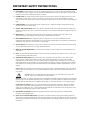
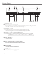
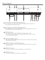
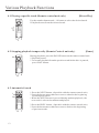
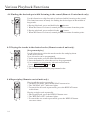
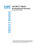
o o o o o o o o o o o o o o o o o o o o o o o o o o o o o o o o o o o o o o o o o o o o o o o o o o o o o o o o o o o o o o o o o o o o o o o o o
OWNER’S MANUAL
o o o o o o o o o o o o o o o o o o o o o o o o o o o o o o o o o o o o o o o o o o o o o o o o o o o o o o o o o o o o o o o o o o o o o o o o o
CDP 1
CD Player
192 kHz / 24 Bit Digital to Analog Coverters
HDCD Decoding
Digital sample rates from 44.1 kHz to 768 kHz
NOTE: Before installing your new component, please read this manual carefully
as it will inform you of the product specifications, proper installation and correct
operating procedures for your unit. Also included in this manual are guidelines
on how to service and care for your new Cary Audio Design product.
CDP 1
CD PLAYER
768
512
384
192
96
POWER
DISPLAY
SAMPLE-RATE
CONVERTER
OPEN/CLOSE
PLAY
PREV.
STOP
CDP 1
HDCD , High Definition Compatible Digital and Pacific Microsonics are either registered trademarks or
trademarks of Pacific Microsonics, Inc. in the United States and /or other countries
.
HDCD system manufactured under license from Pacific Microsonics, Inc.
This product is covered by one or more of the following :
Country
Patent No.
United States
5,479,168 5,638,074 5,640,161 5,808,574 5,838,274 5,854,600 5,864,311 5,872,531
Australia
669114
Other patents pending.
AES/EBU
TOSLINK
COAXIAL
TRIGGER
INPUT
IR
INPUT
44.1kHz - 192kHz DIGITAL OUTPUT
LEFT
ANALOG OUTPUT
Front Panel, Rear Panel & Remote Control
Specifications, Installation
Normal Playback
Various Playback Functions
[
[
RS 232
AC POWER
] 110-120V
] 220-240V
CARY AUDIO DESIGN
CDP 1 HDCD PLAYER
APEX, NC, U.S.A.
AES/EBU
RIGHT
NEXT
192kHz / 24Bit HDCD PLAYER
Complies with FDA radiation
performance standards,
21CFR Subchapter J
This device complies with part
15 of the FCC Rules.Operation
is subject to the following two
conditions:(1) This device may
not cause harmful interference,
and (2) this device must accept
any interference received,
including interference that may
cause undesired operation.
4-9
10-11
12
13-14
Service and Care
15
Warranty
16
1
IMPORTANT SAFETY INSTRUCTIONS
WARNING: To reduce the risk of fire or electric shock, do
not expose this appliance to rain or moisture. The lightning
flash with arrowhead symbol within an equilateral triangle is
intended to alert the user to the presence of un-insulated
dangerous voltage within the product’s enclosure that may
be of sufficient magnitude to constitute a risk of electric
shock to persons.
CAUTION: To reduce the risk of electric shock, do not remove the cover. There are no user serviceable parts inside.
Please refer to qualified personnel for service.
ALERT: The exclamation point within an equilateral triangle is intended to alert the user of the presence of important
operating and maintenance (servicing) instructions in the literature accompanying the component.
1.
READ ALL INSTRUCTIONS: All the safety and operating instructions of your Cary Audio equipment should be read
before power is applied to the equipment.
2.
RETAIN OWNER'S MANUAL: These safety and operating instructions should be retained for future reference.
3.
HEED WARNING: All warnings on the unit and in the operating instructions should be adhered to.
4.
FOLLOW INSTRUCTIONS: All operating and use instructions should be followed.
5.
CLEANING: Unplug the unit from the wall outlet before cleaning. The unit should be cleaned only as recommended
by the manufacturer.
6.
ATTACHMENTS: Do not use attachments not recommended by the unit manufacturer as they may cause hazards.
7.
WATER AND MOISTURE: Do not use the unit near water - for example, near a bath tub, wash bowl, kitchen sink,
or laundry tub; in a wet basement; or near a swimming pool.
8.
ACCESSORIES: Do not place the unit on an unstable cart, stand, tripod, bracket, or table. The unit may fall,
causing serious injury to a child, an adult, or damage to the unit. Mounting of the unit should follow the
manufacturer's instructions and should use a mounting accessory recommended by the manufacturer.
9.
VENTILATION: Slots and openings in the cabinet are provided for ventilation to ensure reliable operation of the
unit and to protect it from overheating. These openings must not be blocked or covered. The top or bottom panel
openings should never be blocked by placing the unit on a bed, sofa, rug, or other similar surface. The unit should
not be installed in a built-in location such as a bookcase or rack unless proper ventilation is provided. There should
be free space of at least 6 inches (16cm) above the unit and an opening behind the unit.
10. GROUNDING OR POLARIZATION: The unit may be equipped with a polarized alternating current line plug (a
plug having one blade wider than the other). This plug will fit into the power outlet only one way. This is a safety
feature. If you cannot insert the plug fully into the outlet, try reversing the plug. If the plug should fail to fit, contact
a licensed electrician to replace your obsolete outlet. Do not defeat the safety purpose of the polarized plug.
11. POWER SOURCES: The unit should be operated only from the type of power source indicated on the marking
label. If you are not sure of the type of power supplied to your home, consult your unit dealer or local power
company.
12. POWER CORD PROTECTION: Power supply cords should be routed so that they are unlikely to be walked on or
pinched by items placed on or against them. Pay close attention to cords where they enter a plug, or a convenience
receptacle, and the point where they exit from the unit.
13. OUTDOOR ANTENNA GROUNDING: If an outside antenna or cable system is connected to the unit, be sure the
antenna or cable system is grounded so as to provide protection against voltage surges and built-up static charges.
Article 810 of the National Electrical Code, NSI/NFPA 70, provides information regarding proper grounding of the
mast and supporting structure, grounding of the lead-in wire to an Antenna-discharge unit, size of grounding
conductors, location of antenna-discharge unit, connection to grounding electrodes, and requirements for the
grounding electrode.
IMPORTANT SAFETY INSTRUCTIONS
14. LIGHTNING: For added protection for the unit during a lightning storm, or when it is left unattended and unused
for long periods of time, unplug it from the wall outlet and disconnect the antenna or cable system. This will prevent
damage to the unit due to lightning and power line surges.
15. POWER LINES: An outside antenna system should not be located in the vicinity of overhead power lines or other
electric light or power circuits, or where it can fall into such power lines or circuits. When installing an outside
antenna system, take extreme care to keep from touching such power lines or circuits as contact with them might be
fatal.
16. OVERLOADING: Do not overload wall outlets, extension cords, or integral convenience receptacles as this can
result in a risk of fire or electric shock.
17. OBJECT AND LIQUID ENTRY: Never push objects of any kind into the unit through openings as they may touch
dangerous voltage points or short-out parts that could result in a fire or electric shock. Never spill liquid of any kind
on the unit.
18. SERVICING: Do not attempt to service the unit yourself as opening or removing covers may expose you to
dangerous voltage or other hazards. Refer all servicing to qualified service personnel.
19. REPLACEMENT PARTS: When replacement parts are required, be sure the service technician has used
replacement parts specified by the manufacturer or have the same characteristics as the original part. Unauthorized
substitutions may result in fire, electric shock or other hazards.
20. SAFETY CHECK: Upon completion of any service or repairs to the unit, ask the service technician to perform safety
checks to determine that the unit is in proper operating condition.
21. WALL OR CEILING MOUNTING: The unit should be mounted to a wall or ceiling only as recommended by the
manufacturer.
22. HEAT: The unit should be situated away from heat sources such as radiators, heat registers, stoves, or other units
(including amplifiers) that produce heat.
23. IMPORTANT SAFETY NOTE: Before connecting a new component such as the DVD 7 to your audio or home
theater system it is always good practice to make certain that all components are turned off, and preferably
unplugged from their AC power source. Many modern electronics products feature automatic turn-on circuits that
may be activated during an installation, causing the potential for damage to electronic components and/or speakers.
Such damage is not covered by product warranties and Cary Audio specifically disclaims responsibility for any such
damage.
Power Cord: The removable power cord that is shipped with the player is specifically designed to be used with this
product. Other AC cords may be used, so consult your dealer for advice on AC power cords and high quality wire in
your system.
AC Fuse: The fuse is located inside the chassis and is not user serviceable. If power does not
come on, contact your authorized service representative.
Wiring: Cables that run inside of walls should have the appropriate markings to indicate compliance with, and listing
by the UL, CSA or other standards required by the UL, CSA, NEC or your local building code. Questions about cables
inside of walls should be referred to a qualified custom installer, or a licensed electrician or low-voltage contractor.
Do Not Open the Cabinet: There are no user serviceable components inside this product. Opening the cabinet
may present a shock hazard, and any modification to the product will void your warranty. If water or any metal
object, such as a paper clip, coin, or staple accidentally falls inside the unit, disconnect it from the AC power source
immediately and contact Cary Audio for further instructions.
24. RECORDING COPYRIGHT: Recording of copyrighted material for other than personal use is illegal without
permission of the copyright holder.
25. NOTE TO CATV SYSTEM INSTALLER: This reminder is provided to call the CATV system installer's attention to
article 820-40 of the NEC, ANSI/NFPA 70, which provides guidelines for proper grounding and, in particular, specifies
that the cable ground shall be connected to the grounding system of the building, as close to the point of cable entry
as practical.
IMPORTANT SAFETY INSTRUCTIONS
26. FCC INFORMATION FOR USER:
CAUTION: ANY changes or modifications not expressly approved by the party responsible
for compliance could void the user's authority to operate the equipment.
NOTE: This equipment has been tested and found to comply with the limits for a Class B digital device pursuant to
Part 15 of the FCC Rules.
These limits are designed to provide reasonable protection against harmful interference in a residential installation.
This equipment generates and can radiate radio frequency energy and, if not installed and used in accordance with
the instructions, may cause harmful interference to radio communications. However, there is no guarantee that
interference will not occur in a particular installation. If this equipment does cause harmful interference to radio or
television reception, which can be determined by turning the equipment off and on, the user is encouraged to try to
correct the interference by one or more of the following measures:
- Reorient or relocate the receiving antenna.
- Increase the separation between the equipment and receiver.
Connect the equipment into an outlet on a circuit different from where the receiver is connected.
27.
OUTDOOR ANTENNA INSTALLATION/SAFE ANTENNA AND CABLE
CONNECTION: If an outside antenna or cable system is connected to
the equipment, be sure the antenna or cable system is grounded so as to
provide protection against built up static charges and voltage surges,
Section 810 of the national Electrical Code, ANSI/NFP A70 (in Canada,
part 1 of the Canadian Electrical Code) provides information with respect
to proper grounding of the mast and supporting structure, grounding of
the lead-in wire to an antenna discharge unit, size of grounding
conductors, location of antenna discharge unit, connection to grounding
electrodes and requirements for the grounding electrode.
Keep Antenna Clear of High Voltage Power Lines or Circuits
An outside antenna system should be located well away from power lines, electric light or power circuits and where
it will never come into contact with these power sources if it should happen to fall. When installing an outside
antenna, extreme care should be taken to avoid touching power lines, circuits or other power sources as this could
be fatal. Because of the hazards involved, antenna installation should be left to a professional.
Front Panel
14
13
12
10
11
768
512
384
192
96
POWER
DISPLAY
SAMPLE-RATE
CONVERTER
OPEN/CLOSE
PLAY
PREV.
STOP
CDP 1
1
1
2
3
4
5
6
7
8
POWER button:
* Press once to turn the power ON.
* Press again to set to the "OFF" position and turn the power off. The player will
enter into "Standby" and the blue LED will light.
2
DISPLAY button:
* Use this button to switch the player display brightness levels.
* There are 3 brightness levels, low, medium and high, plus OFF.
3
SAMPLE-RATE CONVERTER button:
* Use this button to switch the analog output sample-rate converter mode.
OFF(44.1) ---> 96 ---> 192 ---> 384 ---> 512 ---> 768 kHz --->
4
DISC HOLDER:
* Load discs here.
5
DISC HOLDER OPEN/CLOSE button:
* Press this button to open and close the disc holder.
6
PLAY button:
* Press this button to start playback.
7
STOP button:
* Press this button to stop playback.
4
NEXT
192kHz / 24Bit HDCD PLAYER
9
Front Panel
14
13
12
10
11
768
512
384
192
96
POWER
DISPLAY
SAMPLE-RATE
CONVERTER
OPEN/CLOSE
PLAY
PREV.
STOP
CDP 1
1
8
2
3
4
5
6
7
8
AUTOMATIC SEARCH REVERSE button:
* Press this button to return the pickup to the beginning of the present track.
* Press again to return to other tracks.
9
AUTOMATIC SEARCH FORWARD button:
* Press this button to move the pickup forward to the beginning of the next track.
* Press again to move ahead to other tracks.
10
HDCD indicator:
* This indicator lights when the HDCD decoding function is "ON".
* This function decodes HDCD disks at the 44.1 kHz setting ONLY. This is a
part of the HDCD algorithm.
11
ALPHANUMERIC display:
* This multi-character display provides a wide range of information concerning
the operation of the CDP 1.
12
SAMPLE-RATE CONVERTER indicator:
* This indicator lights when the digital and analog output sample-rate converter
function is "ON".
13
DISPLAY indicator:
* This indicator lights when display brightness is set "OFF" mode.
14
POWER indicator:
* This indicator lights when the player is switched off.
5
NEXT
192kHz / 24Bit HDCD PLAYER
9
Rear Panel
10
HDCD , High Definition Compatible Digital and Pacific Microsonics are either registered trademarks or
trademarks of Pacific Microsonics, Inc. in the United States and /or other countries
.
HDCD system manufactured under license from Pacific Microsonics, Inc.
This product is covered by one or more of the following :
Country
Patent No.
United States
5,479,168 5,638,074 5,640,161 5,808,574 5,838,274 5,854,600 5,864,311 5,872,531
Australia
669114
Other patents pending.
AES/EBU
TOSLINK
COAXIAL
TRIGGER
INPUT
IR
INPUT
[
[
RS 232
CARY AUDIO DESIGN
CDP 1 HDCD PLAYER
APEX, NC, U.S.A.
Complies with FDA radiation
performance standards,
21CFR Subchapter J
AES/EBU
44.1kHz - 192kHz DIGITAL OUTPUT
RIGHT
This device complies with part
15 of the FCC Rules.Operation
is subject to the following two
conditions:(1) This device may
not cause harmful interference,
and (2) this device must accept
any interference received,
including interference that may
cause undesired operation.
LEFT
ANALOG OUTPUT
1
1
2
3
AC POWER
] 110-120V
] 220-240V
4
5
6
7
8
9
RIGHT CHANNEL ANALOG OUTPUT JACK (AES/EBU BALANCED):
* Use this jack for connection to the amplifier's balanced input jack.
2
RIGHT CHANNEL ANALOG OUTPUT JACK (RCA UNBALANCED):
* Use this jack for connection to the amplifier's RCA unbalanced input jack.
3
LEFT CHANNEL ANALOG OUTPUT JACK (RCA UNBALANCED):
* Use this jack for connection to the amplifier's RCA unbalanced input jack.
4
LEFT CHANNEL ANALOG OUTPUT JACK (AES/EBU BALANCED):
* Use this jack for connection to the amplifier's balanced input jack.
5
DIGITAL OUTPUT JACK (TOSLINK):
* 44.1 kHz-192 kHz digital data is output from this jack.
6
DIGITAL OUTPUT JACK (COAXIAL):
* 44.1 kHz-192 kHz digital data is output from this jack.
7
DC TRIGGER INPUT TERMINALS:
* Connect a device that can triggered by DC + 12V.
6
Rear Panel
10
HDCD , High Definition Compatible Digital and Pacific Microsonics are either registered trademarks or
trademarks of Pacific Microsonics, Inc. in the United States and /or other countries
.
HDCD system manufactured under license from Pacific Microsonics, Inc.
This product is covered by one or more of the following :
Country
Patent No.
United States
5,479,168 5,638,074 5,640,161 5,808,574 5,838,274 5,854,600 5,864,311 5,872,531
Australia
669114
Other patents pending.
AES/EBU
TOSLINK
COAXIAL
TRIGGER
INPUT
IR
INPUT
[
[
RS 232
CARY AUDIO DESIGN
CDP 1 HDCD PLAYER
APEX, NC, U.S.A.
Complies with FDA radiation
performance standards,
21CFR Subchapter J
AES/EBU
44.1kHz - 192kHz DIGITAL OUTPUT
RIGHT
This device complies with part
15 of the FCC Rules.Operation
is subject to the following two
conditions:(1) This device may
not cause harmful interference,
and (2) this device must accept
any interference received,
including interference that may
cause undesired operation.
LEFT
ANALOG OUTPUT
1
8
3
2
AC POWER
] 110-120V
] 220-240V
4
5
6
7
8
9
IR INPUT JACK:
* Use this jack to connect external IR sensors.
9
POWER INPUT(AC IN):
* Connect to an AC power supply using the included power supply cord.
10
RS 232 PORT:
* The RS-232 port is used in conjunction with an external controller to control the
operation of the CDP 1 by using an external device.(This is for custom installation
use. Consult your dealer for more information.)
* The pin assignments of the XLR-type male analog outputs:
1
3
2
Pin 1: Signal ground
Pin 2: Signal + (non-inverting)
Pin 3: Signal - (inverting)
Connector ground lug: chassis ground
Refer to your amplifier's operating manual to verify that the XLR pin
assignments of its input connectors correspond to the CDP 1.
If they are different, wire the XLR cable so that the appropriate XLR
output pin connects to the equivalent XLR input pin.
Remote Control
This button switches the power on and off.
This button opens and closes the CD
loading tray.
SRC
This button interrupts and resumes play.
BRIGHT
Start play. Playing a program.
1
2
3
REPEAT
4
5
6
DELETE
7
8
9
PROGRAM
+10
0
CLEAN
TIME
Stops play.
This button mutes the sound.
Press again to resume sound.
SRC
-
VOLUME
+
Select the sample-rate converter on or off,
and cycle through sample-rate settings.
MUTE
POWER
DELETE
AMPLIFIER USE ONLY
<
INPUT SELECTOR
L
BALANCED
-
VOLUME
Clears a program.
>
R
PROGRAM
Presets tracks to be played by keying in
track numbers.
+
Fast search for a passage.
Selects another track during play.
CDP 1 R/C
REPEAT
Repeat play.
8
Remote Control
BRIGHT
Select the display brightness levels - low,
medium, high, and OFF settings available.
1
Digit keys.
SRC
CLEAN
Clears the last track number during
programming.
TUBE
BRIGHT
TIME
Displays the remaining time of a track or
it displays the total remaining time of a disc.
1
3
2
REPEAT
VOLUME
4
5
6
DELETE
7
8
9
PROGRAM
+10
0
CLEAN
TIME
-
VOLUME
Control the volume. (0 dB to 63 dB)
CARY amplifier use only
+
MUTE
POWER
AMPLIFIER USE ONLY
MUTE
POWER
AMPLIFIER USE ONLY
<
L
INPUT SELECTOR
BALANCED
>
R
<
-
VOLUME
>
+
CDP 1 R/C
9
INPUT SELECTOR
L
BALANCED
-
VOLUME
R
+
Specifications
Operating the CDP 1 CD player is a simple procedure, since each unit is designed for long term
stability in virtually any home operating situation. However, if the unit is operated outside the
parameters outline in this owner's manual, damage may result. Please read this manual carefully
before putting your new Cary Audio Design CDP 1 in operation.
1.1 Specifications
The following section describes the CDP 1 CD player basic specifications.
Specifications are subject to change without notice or obligation.
CD Mechanism
Triple-beam laser, multi speed CD/DVD ROM transport
Formats
CD AUDIO (CD-DA), CD-R, CD-RW
Master Clock Jitter
Below measurable levels
Digital Filter
CARY DSP 300 with HDCD decoding
Digital / Analog Converters
Two (2) Burr Brown PCM 1792u
Analog Filter
3
Analog Outputs
Balanced XLR, Single - Ended RCA
Digital Output
Coaxial, Toslink operating at Sample Frequency (FS)
from 44.1 kHz / 16 bit to 192 kHz / 24 bit
Frequency Range
2 Hz - 22 kHz (44.1 kHz)
Amplitude Linearity
0.1 dB (20 Hz-20 kHz)
Phase Linearity
3 (20 Hz - 20 kHz)
Frequency Response
129 dB (1 kHz)
Signal-to-Noise Ratio
122 dB (1 kHz)
Channel Separation
104 dB (1kHz)
Total Harmonic Distortion
0.003 % (1 kHz)
Audio Output level
3.0 V RMS (220
Balanced
+3.0
-
Trigger Input
12.0 V DC
IR Input
PHILIPS RC 5 IR code
Comms.
RS 232 full remote configuration interface
Power Input
Configured at the factory for either
110-117 or 220-234 V AC, 50-60 Hz
Power Consumption
50 Watts
10
rd
Order Bessel
O
V RMS (440
output impedance)
output impedance)
Installation
This section describes the unpacking and installation procedures for the CDP 1 player.
WARNING
MAKE NO ATTEMPT TO PUT THE CDP 1 CD PLAYER IN SERVICE WITH
THE TOP COVER REMOVED. CONTACT WITH HIGH VOLTAGE INSIDE
THE CDP1 CD PLAYER CAN BE FATAL!
2.1 Unpacking
All Cary Audio Design shipping containers have been specifically designed to protect their
contents and special care has been taken to prevent damage under normal shipping conditions.
Mishandling should be evident upon inspection of the shipping container. If the CDP 1 player
mechanism or other damage is found after unpacking and visual inspection, take care not to
destroy the evidence so that the shipping agent may inspect the damage. If necessary, document
the damage with photographs and contact the shipping company immediately.
Carefully remove your CDP 1 CD player from its packing carton and examine it closely for signs
of shipping damage. It is highly recommended to save all original packing cartons to protect your
CDP 1 from damage should you wish to store it or ship it for after-sales service. Replacement
cartons and packing are available at a nominal charge from Cary Audio Design, ifever required.
2.2 Placement
In general, the location of your new CDP 1 is not critical. However, certain precautions must be
taken to ensure optimum performance. Avoid extremely hot locations such as near radiators
or other heating units. Avoid getting it wet or using it near water. Do not stack the CDP 1 on top
of a power amplifier. Allow 4-6 inches (10-15cm) above the unit for proper ventilation.
2.3 Power Requirement
The CDP 1 CD player is designed to operate from AC mains current. The design AC voltage is
either 110-117V or 220-234V AC at 50-60 Hz.
2.4 Connections
Digital Outputs: The outputs send a digital signal and should only be connected to the
appropriate digital signal input of an accompanying component.
Analog Outputs: These are for connection to the CD or AUX input jacks of an
appropriate preamplifier or integrated amplifier.
11
Normal Playback
3.1 Starting Playback
768
512
384
192
96
POWER
DISPLAY
SAMPLE-RATE
CONVERTER
OPEN/CLOSE
PLAY
PREV.
STOP
CDP 1
1
1
3
2
4
Press the POWER button to turn on the power.
2 Press the OPEN/CLOSE button.
* The disc holder opens.
3 Load the disc you want to play.
4 Press the PLAY button.
* Playback starts.
* Playback stops automatically after the last track on the disc has been played.
3.2 Stopping Playback
1 During playback, press the STOP button.
* Playback stops.
12
NEXT
192kHz / 24Bit HDCD PLAYER
Various Playback Functions
4.1 Playing a specific track (Remote control unit only)
Use the number buttons and + 10 button to select the desired track.
* Playback starts from the selected track.
SRC
BRIGHT
1
1
2
3
REPEAT
4
5
6
DELETE
PROGRAM
7
8
9
+10
0
CLEAN
-
[Direct Play]
TIME
VOLUME
+
MUTE
POWER
AMPLIFIER USE ONLY
INPUT SELECTOR
<
L
BALANCED
-
VOLUME
>
R
+
4.2 Stopping playback temporarily (Remote Control unit only)
1
SRC
BRIGHT
1
2
3
REPEAT
4
5
6
DELETE
PROGRAM
7
8
9
+10
0
CLEAN
-
VOLUME
[Pause]
During playback, press the PAUSE button on the remote control unit.
* Playback pauses.
* To resume playback from the position at which the disc is paused,
press PLAY button.
TIME
+
MUTE
POWER
AMPLIFIER USE ONLY
INPUT SELECTOR
<
L
BALANCED
-
VOLUME
>
R
+
4.3 Automatic Search
1
2
SRC
BRIGHT
1
2
3
4
5
6
DELETE
7
8
9
PROGRAM
-
TIME
CLEAN
0
+10
REPEAT
VOLUME
+
MUTE
POWER
AMPLIFIER USE ONLY
<
13
INPUT SELECTOR
L
BALANCED
-
VOLUME
1.Press the NEXT button. (Operable with the remote control unit)
* Press the button more than once to move ahead to the beginning
of subsequent tracks.
* When the NEXT button is pressed during random playback, the
next track is selected at random and played.
>
R
+
2.Press the PREV. button. (Operable with the remote control unit)
* Press the button more than once to move back to the beginning
of previous tracks.
Various Playback Functions
4.4 Finding the desired spot while listening to the sound (Remote Control unit only)
1
2
Use this function to skip forward or backward while listening to the sound.
This function comes in handy for finding the desired spot in the middle of
long tracks.
SRC
BRIGHT
1
2
3
4
5
6
DELETE
7
8
9
PROGRAM
+10
0
CLEAN
TIME
-
VOLUME
REPEAT
1.During Playback, press and hold in the
button.
* When the button is released, normal playback resumes from that point.
+
MUTE
POWER
AMPLIFIER USE ONLY
INPUT SELECTOR
<
L
BALANCED
-
VOLUME
2.During playback, press and hold in the
button.
* When the button is released, normal playback resumes from that point.
>
R
+
4.5 Playing the tracks in the desired order (Remote control unit only)
SRC
3
BRIGHT
2
1
1
2
3
4
5
6
DELETE
7
8
9
PROGRAM
+10
CLEAN
0
-
REPEAT
VOLUME
TIME
+
MUTE
POWER
AMPLIFIER USE ONLY
INPUT SELECTOR
<
L
BALANCED
-
VOLUME
>
R
+
[Programmed play]
Use this function to select the tracks on the disc and play them
in the desired order.
Up to 99 tracks can be programmed.
1.In the stop mode, press the PROGRAM button.
2.Press the number to select the track to be programmed.
* For example, to program the 3rd track and 9th track,
Press PROGRAM , 3 and 9 .
3.Press the PLAY button.
* The tracks are played in the programmed order.
4.6 Repeat play (Remote control unit only)
SRC
BRIGHT
1
1
2
3
REPEAT
4
5
6
DELETE
PROGRAM
7
8
9
+10
0
CLEAN
-
VOLUME
TIME
+
MUTE
POWER
AMPLIFIER USE ONLY
<
14
INPUT SELECTOR
L
BALANCED
-
VOLUME
Playing all the tracks repeatedly.
1. In the PLAY mode, press the REPEAT button twice.
* The "REPEAT ALL" indicator lights.
* To cancel the all-track repeat mode, press the REPEAT button
a third time.
>
R
+
Playing a single track repeatedly.
1.During playback, press the REPEAT button once.
* The "REPEAT ONE" indicator lights.
* To cancel the one-track repeat mode, press the REPEAT button
two more times.
Service and Care
5.1 CDP 1 Care and Cleaning
The cabinet housing and front panel of the CDP 1 may be cleaned with a soft cloth and Windex
or a mild window cleaner. The frequency of cleaning will be governed by the operating
environment cleanliness. Do not use benzene, harsh or abrasive chemicals to clean the front or
rear panel as they may remove or damage the labels.
5.2 Factory Service
Careful consideration has been given to the design of you CDP 1 CD player to keep maintenance
problems to a minimum. Any service problems should be referred to our Customer Service
Department phone number (919) 355-0010 from 1-5 PM US East Coast Time Zone.
Do NOT return the CDP 1 to the factory without a return authorization number ( RA ) from the
Customer Service Department.
Cary Audio Design will assume no responsibility if the shipping company refuses to pay
damage due to your improper packing or lack of insurance should the unit be lost or damaged
in shipment. Please retain and always use the original shipping carton for the CDP 1 in the event
that you move or after service is needed.
CAUTIONS
NEVER REMOVE OR INSERT THE BACK PANEL AC PLUG
WHEN THE UNIT IS ON OR THE AC CORD IS PLUGGED
INTO THE WALL.
PLEASE OBSERVE THE SAFETY DIRECTIONS IN THIS MANUAL
15
UNITED STATES LIMITED WARRANTY
Cary Audio Design warrants to the original United States purchaser for use in the United States that Cary
Audio Design vacuum tube or solid state power amplifiers, surround sound processors or preamplifiers shall
be free from defects in parts or workmanship for three (3) years from the date of the original purchase.
Vacuum tubes, if any are used in the component, are offered a 90 day from purchase date exchange policy
against defects with the exception of the CAVT 300B vacuum tube which has a (1) one year from purchase
date exchange policy. Any digital drive design, whether a Cary Audio Design CD or SACD player or a Cary
Cinema DVD player, has a limited one year parts and labor warranty against defects in manufacture. This is
a limited warrant, for the original purchaser only and does not transfer to any subsequent owner.
During the limited warranty period, Cary Audio Design or an authorized Cary Audio Design service facility
will provide free of charge both parts and labor necessary to correct any defects in material or
workmanship.
To obtain such warranty service, the original purchaser must:
1. Complete and send in the warranty Registration Card within 15 days of purchase.
2. If claiming service the owner must send a fully filled in copy of the original sales receipt along with
any unit sent in for service showing the AUTHORIZED CARY AUDIO DESIGN DEALER’S name, the
new selling price, the buyer’s name, e-mail or phone number and address on the receipt. Blank
receipts will NOT validate the limited warranty for service.
3. Notify Cary Audio Design as soon as possible after the discovery of a possible defect and submit
the following information to determine eligibility for warranty:
(a) The model number and serial number;
(b) A fully filled in copy of the original sales receipt showing the original selling price, purchasers
name and address filled in by an AUTHORIZED CARY AUDIO DESIGN DEALER with the original
date of purchase shown on the form;
(c) a detailed description of the problem.
4. Deliver the product to Cary Audio Design or the nearest authorized service facility or ship with all
freight and insurance charges prepaid, in its original packing container or equivalent, to Cary
Audio.
Correct maintenance, repair and use are important to obtain performance from this product. Therefore,
please carefully read the Operating Manual. This warranty does not apply to any defect that Cary Audio
Design in its sole discretion determines is due to:
1. Improper maintenance or repair, including the installation of parts or accessories that do not
conform to the quality and the specifications of the original parts.
2. Misuse, abuse, neglect or improper installation.
3. Accidental or incidental damage.
WARRANTY DISCLAIMER
Except for the express warranties stated herein, Cary Audio Design disclaims all other warranties including,
without limitation, all implied warranties of merchantability and fitness for a particular purpose. The
foregoing constitutes Cary Audio Design’s entire obligation with respect to this product, and the original
purchaser and any user or owner shall have no other claim for incidental or consequential damages. Some
states do not allow the exclusion or limitation of incidental or consequential damages, so the above
limitation and exclusion may not apply to you. This warranty gives legal rights and you may also have other
rights, which vary from state to state.
EXCLUSIVE REMEDY
Notwithstanding the foregoing, the purchaser’s exclusive remedy for any breach of warranty, express or
implied, is limited to the repair or replacement of the defective unit or the refund of the purchase price, at
the option of Cary Audio Design. Under no circumstances is Cary Audio Design liable for incidental or
consequential damages. Any implied warranties imposed by law terminate one (1) year from the date of
purchase.
INTERNATIONAL PURCHASERS (Export markets)
Cary Audio Design warrants its merchandise to purchasers within the United States exclusively for use within
the United States of America. It provides no other warranties, expressed or implied. If you are living
outside the USA, please consult with your local dealer or distributor to determine the details of your local
warranty.
1020 Goodworth Drive, Apex, NC 27539
phone 919-355-0010
fax 919-355-0013
www.caryaudio.com
o o o o o o o o o o o o o o o o o o o
CARY AUDIO DESIGN
o o o o o o o o o o o o o o o o o o o o o o o o o o o o o o o o o o o o o o o o o o o o o o o o o o o o o o o o o o o o o o o o o o o o o o o o o