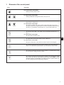
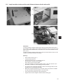
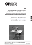
1
540-100-1 CNC-Doppelsteppstich-Knopflochautomat CNC double lockstitch buttonholer Bedienanleitung / Operating Instructions 1 Aufstellanleitung / Installation Instructions 2 Serviceanleitung / Service Instructions 3 Postfach 17 03 51, D-33703 Bielefeld Potsdamer Straße 190, D-33719 Bielefeld Deutsch/Englisch Telefon +49 (0) 5 21/ 59 25-00 Telefax +49 (0) 5 21/ 9 25 24 35 www.duerkopp-adler.com Ausgabe / Edition: 09/2009 Änderungsindex Rev. index: 01.0 Printed in Federal Republic of Germany Teile-Nr.:/Part-No.: 0791 540001 Alle Rechte vorbehalten. Eigentum der Dürkopp Adler AG und urheberrechtlich geschützt. Jede, auch auszugsweise Wiederverwendung dieser Inhalte ist ohne vorheriges schriftliches Einverständnis der Dürkopp Adler AG verboten. All rights reserved. Property of Dürkopp Adler AG and copyrighted. Reproduction or publication of the content in any manner, even in extracts, without prior written permission of Dürkopp Adler AG, is prohibited. Copyright ã 2009 - Dürkopp Adler AG Foreword This instruction manual is intended to help the user to become familiar with the machine and take advantage of its application possibilities in accordance with the recommendations. The instruction manual contains important information on how to operate the machine securely, properly and economically. Observation of the instructions eliminates danger, reduces costs for repair and down-times, and increases the reliability and life of the machine. The instruction manual is intended to complement existing national accident prevention and environment protection regulations. The instruction manual must always be available at the machine/sewing unit. The instruction manual must be read and applied by any person that is authorized to work on the machine/sewing unit. This means: – – – Operation, including equipping, troubleshooting during the work cycle, removing of fabric waste, Service (maintenance, inspection, repair) and/or Transport. The user also has to assure that only authorized personnel work on the machine. The user is obliged to check the machine at least once per shift for apparent damages and to immediatly report any changes (including the performance in service), which impair the safety. The user company must ensure that the machine is only operated in perfect working order. Never remove or disable any safety devices. If safety devices need to be removed for equipping, repairing or maintaining, the safety devices must be remounted directly after completion of the maintenance and repair work. Unauthorized modification of the machine rules out liability of the manufacturer for damage resulting from this. Observe all safety and danger recommendations on the machine/unit! The yellow-and-black striped surfaces designate permanend danger areas, eg danger of squashing, cutting, shearing or collision. Besides the recommendations in this instruction manual also observe the general safety and accident prevention regulations! General safety instructions The non-observance of the following safety instructions can cause bodily injuries or damages to the machine. 1. The machine must only be commissioned in full knowledge of the instruction book and operated by persons with appropriate training. 2. Before putting into service also read the safety rules and instructions of the motor supplier. 3. The machine must be used only for the purpose intended. Use of the machine without the safety devices is not permitted. Observe all the relevant safety regulations. 4. When gauge parts are exchanged (e.g. needle, presser foot, needle plate, feed dog and bobbin) when threading, when the workplace is left, and during service work, the machine must be disconnected from the mains by switching off the master switch or disconnecting the mains plug. 5. Daily servicing work must be carried out only by appropriately trained persons. 6. Repairs, conversion and special maintenance work must only be carried out by technicians or persons with appropriate training. 7. For service or repair work on pneumatic systems, disconnect the machine from the compressed air supply system (max. 7-10 bar). Before disconnecting, reduce the pressure of the maintenance unit. Exceptions to this are only adjustments and functions checks made by appropriately trained technicians. 8. Work on the electrical equipment must be carried out only by electricians or appropriately trained persons. 9. Work on parts and systems under electric current is not permitted, except as specified in regulations DIN VDE 0105. 10. Conversion or changes to the machine must be authorized by us and made only in adherence to all safety regulations. 11. For repairs, only replacement parts approved by us must be used. 12. Commissioning of the sewing head is prohibited until such time as the entire sewing unit is found to comply with EC directives. 13. The line cord should be equipped with a country-specific mains plug. This work must be carried out by appropriately trained technicians (see paragraph 8). It is absolutely necessary to respect the safety instructions marked by these signs. Danger of bodily injuries ! Please note also the general safety instructions. Index Page: Part 3: Service Instructions Class 540-100-1 1. 1.1 1.1.1 1.1.2 Elements of the control panel Altering parameter values . . . . . . . . . . . . . . . . . . . . . . . . . . . . . . . . . . . . . . . . . Numerical values . . . . . . . . . . . . . . . . . . . . . . . . . . . . . . . . . . . . . . . . . . . . . . Selection of a parameter . . . . . . . . . . . . . . . . . . . . . . . . . . . . . . . . . . . . . . . . . . 4 4 4 2. 2.1 Menu structure technician mode (overview) Submenu machine configuration (overview) . . . . . . . . . . . . . . . . . . . . . . . . . . . . . . 6 3. Calling up the technician mode and entering the code . . . . . . . . . . . . . . . . . . . . . 7 4. 4.1 4.1.1 4.1.2 4.1.3 4.1.4 4.1.5 4.1.6 4.2 4.2.1 4.2.2 4.3 4.3.1 4.3.1.1 4.3.1.2 4.3.1.3 4.3.1.4 4.3.1.5 4.4.1.6 4.4.1.7 4.4.2 4.4.3 4.4.3.1 4.4.3.2 4.4.3.3 4.4.3.4 Main menu of the technician mode Submenu machine configuration . . . . . . . . . . . . . . . Submenu user . . . . . . . . . . . . . . . . . . . . . . . . . . Submenu for soft start setting. . . . . . . . . . . . . . . . . Submenu for determining the equipment . . . . . . . . . . Submenu for thread monitor configuration . . . . . . . . . Submenu for the configuration of condensed stitches . . Submenu for entering machine times . . . . . . . . . . . . Submenu for the configuration of the operating elements Submenu for selecting the menu language . . . . . . . . . Submenu for setting date and time . . . . . . . . . . . . . Submenu for test functions . . . . . . . . . . . . . . . . . . Submenu Multitest . . . . . . . . . . . . . . . . . . . . . . . Submenu output test . . . . . . . . . . . . . . . . . . . . . . Submenu input test . . . . . . . . . . . . . . . . . . . . . . . Submenu automatic input test . . . . . . . . . . . . . . . . Submenu sewing motor test. . . . . . . . . . . . . . . . . . Submenu step motor test . . . . . . . . . . . . . . . . . . . Submenu RAM test . . . . . . . . . . . . . . . . . . . . . . . Submenu EPROM test . . . . . . . . . . . . . . . . . . . . . Submenu DAC III . . . . . . . . . . . . . . . . . . . . . . . . Submenu memo-dongle . . . . . . . . . . . . . . . . . . . . Dongle contents . . . . . . . . . . . . . . . . . . . . . . . . . Submenu loading . . . . . . . . . . . . . . . . . . . . . . . . Submenu saving . . . . . . . . . . . . . . . . . . . . . . . . Formatting . . . . . . . . . . . . . . . . . . . . . . . . . . . . . . . . . . . . . . . . . . . . . . . . . . . . . 7 8 8 8 9 10 11 11 11 11 12 12 13 13 14 14 14 14 14 15 15 15 16 17 18 5. 5.1 5.2 Knife setting Aligning the knife and adjusting the knife height . . . . . . . . . . . . . . . . . . . . . . . . . . . Setting of the knife incision damper . . . . . . . . . . . . . . . . . . . . . . . . . . . . . . . . . . . 19 20 . . . . . . . . . . . . . . . . . . . . . . . . . . . . . . . . . . . . . . . . . . . . . . . . . . . . . . . . . . . . . . . . . . . . . . . . . . . . . . . . . . . . . . . . . . . . . . . . . . . . . . . . . . . . . . . . . . . . . . . . . . . . . . . . . . . . . . . . . . . . . . . . . . . . . . . . . . . . . . . . . . . . . . . . . . . . . . . . . . . . . . . . . . . . . . . . . . . . . . . . . . . . . . . . . . . . . . . . . . . . . . . . . . . . . . . . . . . . . . . . . . . . . . . . . . . . . . . . . . . . . . . . . . . . . . . . . . . . . . . . . . . . . . . . . . . . . . . . . . . . . . . . . . . . . . . . . . . . . . . . . . . . . . . . . . . . . . . . . . . . . . . . . . . . . . . . . . . . . . . . . . . . . . . . . . . . . . . . . . . . . . . . . . . . . . . . . . . . . . . . . . . . . . . . . . . . . . . . . . . . . . . . . . . . . . . . . . . . . . . . . . . . . . . . . . . . . . . . . . . . . . . . . . . . . . . . . . . . . . . . . . . . . . . . . . . . . . . . . . . . . . . . . . . . . . . . . . . . . . . . . . . . . 3 Index Page: 6. 6.1 6.2 6.3 6.4 6.5 6.6 6.7 Hook and needle bar Needle position . . . . . . . . . . . . . . . . . . . . . . . Reference position of the needle bar . . . . . . . . . . Setting the adjusting sheet . . . . . . . . . . . . . . . . Loop formation stroke position and distance between Needle bar height . . . . . . . . . . . . . . . . . . . . . . Needle protection . . . . . . . . . . . . . . . . . . . . . . Alignment of the bobbin case holder. . . . . . . . . . . . . . . . . . 21 21 22 23 24 25 25 7. Aligning the throat plate as to the needle . . . . . . . . . . . . . . . . . . . . . . . . . . . . . . 26 8. 8.1 8.2 Thread tension plate Thread puller adjustment . . . . . . . . . . . . . . . . . . . . . . . . . . . . . . . . . . . . . . . . . Thread controller spring and thread regulator . . . . . . . . . . . . . . . . . . . . . . . . . . . . . 26 27 9. 9.1 9.2 9.3 9.4 Sewing basket Setting of the cloth presser block (lifting stroke) . . . Lifting / Lowering speed of the sewing basket . . . . . Alignment of the sewing basket as to the throat plate Reference position of the sewing basket . . . . . . . . . . . . 28 28 29 30 10. 10.1 10.2 Bobbin thread scissors Setting of the closing path . . . . . . . . . . . . . . . . . . . . . . . . . . . . . . . . . . . . . . . . . Adjusting the spring sheet of the thread rest . . . . . . . . . . . . . . . . . . . . . . . . . . . . . . 31 32 11. 11.1 11.2 11.3 11.4 11.5 11.6 11.7 11.8 11.9 11.10 Needle thread scissors Function sequence . . . . . . . . . . . . . . . . . . . Removal and check of the needle thread scissors Alignment of the scissors block. . . . . . . . . . . . Scissors swivelled in . . . . . . . . . . . . . . . . . . Height adjustment. . . . . . . . . . . . . . . . . . . . Scissors swivelled out . . . . . . . . . . . . . . . . . Distance to the needle . . . . . . . . . . . . . . . . . Opening the scissors . . . . . . . . . . . . . . . . . . Setting of the closing path . . . . . . . . . . . . . . . Setting the time for opening the scissors . . . . . . . . . . . . . . . . 33 34 35 37 38 38 39 39 40 40 12. Machine stop position . . . . . . . . . . . . . . . . . . . . . . . . . . . . . . . . . . . . . . . . . . 41 13. Bobbin winder . . . . . . . . . . . . . . . . . . . . . . . . . . . . . . . . . . . . . . . . . . . . . . . 42 14. Solenoid valves . . . . . . . . . . . . . . . . . . . . . . . . . . . . . . . . . . . . . . . . . . . . . . 43 15. Exchange of the sewing basket . . . . . . . . . . . . . . . . . . . . . . . . . . . . . . . . . . . . 44 16. Stretching the drive belts . . . . . . . . . . . . . . . . . . . . . . . . . . . . . . . . . . . . . . . . 45 . . . . . . . . . . . . . . . . . . . . . . . . . . . . . . . . . . . . . . hook and . . . . . . . . . . . . . . . . . . . . . . . . . . . . . . . . . . . . . . . . . . . . . . . . . . . . . . . . . . . . . . . . . . . . . . . . . . . . . . . . . . . . . . . . . . . . . . . . . . . . . . . . . . . . . . . . . . . . . needle . . . . . . . . . . . . . . . . . . . . . . . . . . . . . . . . . . . . . . . . . . . . . . . . . . . . . . . . . . . . . . . . . . . . . . . . . . . . . . . . . . . . . . . . . . . . . . . . . . . . . . . . . . . . . . . . . . . . . . . . . . . . . . . . . . . . . . . . . . . . . . . . . . . . . . . . . . . . . . . . . . . . . . . . . . . . . . . . . . . . . . . . . . . . . . . . . . . . . . . . . . . . . . . . . . . . . . . . . . . . . . . . . . . . . . . . . . . . . . . . . . . . . . . . . . . . . . . . . . . . . . . . . . . . . . . . . . . . . . . . . . . . . . . . . . . . . . . . . . . . . . . . . . . . . . . . . . . . . . . . . . . . . . . . . . . . . . . . . 1. Elements of the control panel Key Function If no text field is activated: – Change to the parent menu. If a text field is activated: – Change between the figures tenth, unit, ten etc. – Change between the lines in the menus. The selected line is always dark-shadowed. If a text field is activated: – Increase or reduce the value of the respective figure by one or change between the parameters in case of functions with several choices, e.g. between “Push button on“ and “Push button off“. – Activate the text field. The value can be altered with the keys “ñ“ and “ò“. If a text field is activated: – The set value is taken over. – 3 You get back to the main menu from a submenu. If a text field is activated: – An input is aborted. The previous value remains unchanged. – The control changes from the sewing mode to the programming mode. The buttonhole parameters can be altered in this mode. – The control changes from the sewing mode or programming mode to the sequence programming mode. – The control changes from the sewing mode to the technician mode. This mode can only be activated by entering a code 25483. In this operating state it is possible to set basic machine parameters and to call up diagnosis and adjusting programs. 3 1.1 Altering parameter values 1.1.1 Numerical values Numerical values can be altered as follows: – Select the line with the value to be altered with the cursor keys ñ and ò. – Actuate the OK key. The cursor flashes under a digit of the numerical value. – Change between the digits with the cursor keys ï and ð. – Increase or reduce the value of the selected digit with the cursor keys ñ and ò. In case of parameters which cannot optionally be altered another possible parameter value is indicated by actuating the cursor keys ñ and ò. – Actuate the OK key. The set value is taken over. – If the set value is not to be taken over, actuate the ESC key. The initially set value is restored 1.1.2 Selection of a parameter Some parameters allow to choose between several possibilities. The parameter can be altered as follows: – Select the line with the value to be altered with the cursor keys ñ and ò. – Actuate the OK key. – Change between the possibilities with the cursor keys ñ and ò. The selected parameter is displayed. – Actuate the OK key. The set parameter or value is taken over. – If the set parameter or value is not to be taken over, actuate the ESC key. The initially set parameter or value is restored. 4 2. Menu structure technician mode (overview) Parameter Soft start Equipment X- /Y- Correction Submenu: Machine configuration Thread monitor Condensed stitches Subclasses Times Counter (totalizer) : Machine User configuration Display Selection: German, English, Italian, Parameter Language Hour : Input Minute: Input Day: Input Set date/time Month: Input Year: Input Lock P: Selection Hand switch: Selection Service 3 Multitest Output test Input test Auto input Sewing motor test Step motor test Events RAM test DAC III EPROM test Data reset Memo dongle Time/Date: Display Temperature DAC III: Interm. circuit voltage: Display Display Buttonhole data Machine complete Content Loading Save Format 5 2.1 Submenu machine configuration (overview) Max. speed: Input Speed basting stitches: Input Scissors is moved out: Input n-stitches b. u. bartack/bartack tension on: Input n-stitches b. l. bartack/bartack tension on: Input n-stitches b. lip there/lip tension on: Input n-stitches b. lip back/lip tension on: Input n-stitches b. seam beginning/lip tension on: Input Number of stitches: Speed: Input Input Parameter Basket length: Selection Free basket length: Input Soft start Basket width: Equipment Free basket width: Thread monitor Knife length: Condensed stitches Pressure monitor: Selection Input Input Input Times Counter (totalizer) Repair mode: Selection Needle thread mon. on/off: Selection Number of stitches: Input Stitch length x: Input Stitch length y: Input Position last stitch: Input 6 3. Calling up the technician mode and entering the code In order to get into the technician mode a code has to be entered. For this purpose please proceed as follows: – Press the F key in the sewing mode. A window for entering the code appears. – Enter the technician code 25483. Confirm with the OK key. Note If a wrong code has been entered, the automate returns to the sewing mode. 4. Main menu of the technician mode No. Parameter name Symbol Description T1 Machine Selection of the submenu for the machine configuration T2 User configuration Selection of the submenu for the configuration of the control elements T3 Service Selection of the submenu for test functions 3 4.1 Submenu Machine configuration No. Parameter name Symbol Range T1.1 Parameter - Selection of the submenu for parameter setting T1.2 Soft start - Selection of the submenu for soft start setting T1.3 Equipment - Selection of the submenu for equipment definition T1.4 Thread monitor - Selection of the submenu for thread monitor options T1.5 Condensed stitches - Selection of the submenu for setting of condensed stitches T1.7 Times - Selection of the submenu for entering machine times T1.8 Counter (totalizer) buttonholes ever sewn 0 … 99,999,999 Description Display of the counter of all buttonholes ever sewn The value cannot be selected or edited. 7 4.1.1 No. Parameter name T1.1.1 Max. speed 200 … 4000 Setting of the maximum speed in the sewing mode. The speed can be altered in steps of 100. T1.1.2 Speed basting stitches 200 … 4000 Setting of the speed for the basting stitches T1.1.3 Move out the scissors 0 … 10 Number of stitches after which the scissors moves out and releases the clamped needle thread T1.1.4 Lip tension before the upper bartack 0 … 10 Number of stitches before the upper bartack with the bartack tension switched on T1.1.5 Lip tension before the lower bartack 0 … 10 Number of stitches before the lower bartack with the bartack tension switched on T1.1.6 Lip tension before the lip back 0 … 10 Number of stitches before the lip back with the lip tension switched on T1.1.7 Lip tension before the lip there 0 … 10 Number of stitches before the lip there with the lip tension switched on T1.1.8 Lip tension after the seam beginning 0 … 10 Number of stitches after the seam beginning after which the lip tension is switched on. Only valid for taper bars. Range Description 0 … 10 Number of stitches of the soft start 4.1.2 Symbol Range Description Submenu for soft start setting No. Parameter name T1.2.1 Number of stitches T1.2.2 Speed 4.1.3 8 User submenu Symbol Speed for the soft start 200 … max. sewing speed according to T1.1.1 Submenu for determining the equipment No. Parameter name Symbol Range T1.3.1 Cage width 3, 4, 6, X mm Selection of the cage width T1.3.2 Free cage width 1,0 … 6,0 mm Only visible if cage width X has been selected for T1.4.1. Enter value for cage width. T1.3.3 Cage length 17, 22, 35, 48, 70, X mm Selection of the cage length T1.3.4 Free cage length 10,0 … 70,0 mm Only visible if cage length X has been selected for T1.4.3. Enter value for cage length. T1.3.5 Knife length 1,0 … 70,0 mm Length of the knife used. (Default-Value: 3.5 mm) T1.3.6 Pressure monitor 0/1 Description Pressure monitor available 4.1.4 Submenu for the thread monitor configuration No. Parameter name T1.4.1 T1.4.2 Symbol Range Description Repair mode A, B, C Selection of the repair mode to be used. Needle thread monitor 0 … 10 Number of stitches not registered by the thread breakage monitor before an error message is displayed. At the value 0 the thread breakage monitor is switched off. Description repair modes T1.4.1 Method A: The buttonhole has to be unstitched and sewn again. – After switching the automate on again the sewing basket lifts and releases the material. The automate is ready for a new sewing cycle. Method B: The buttonhole is completely stitched around anew. – After switching the automate on again the sewing basket remains lowered. The material under the sewing basket remains in its position. – Step the pedal forward (2nd step). The sewing cycle is started. – After the sewing cycle the automate runs in reference position and the sewing basket is lifted. – The material can be taken out. The automate is ready for a new sewing cycle. 3 Method C: The buttonhole is continued to be sewn from the recognized point of thread breakage. – After switching the automate on again the sewing basket remains lowered. The material under the sewing basket remains in its position. – Step the pedal forward (2nd step). The sewing basket moves to the recognized point of thread breakage with the material. – With the cursor keys ñ and ò you can move - not sewing - to the position to continue the sewing cycle. – Step the pedal forward (2nd step). The sewing cycle is started. – After the sewing cycle the automate runs in reference position and the sewing basket is lifted. – The material can be taken out. The automate is ready for a new sewing cycle. 9 4.1.5 Submenu for the configuration of condensed stitches No. Parameter name Symbol T1.5.1 Number of stitches T1.5.2 Stitch length X 0,3 … 2,0 mm Enter the stitch distance of the condensed stitches in direction X T1.5.3 Stitch length Y 0,0 … 0,8 mm Enter the stitch distance of the condensed stitches in direction Y T1.5.4 Position last stitch 0…9 -4 … 4 Lip there Fig. 1 10 Range Lip back Description Enter the number of condensed stitches Enter the position of the last knotting stitch according to fig. 1 4.1.6 Submenu for entering machine times No. Parameter name Symbol Range Description T1.7.1 PedðStart 0 … 9000 ms Delay time between stepping down the pedal position 2 and the sewing motor start T1.7.2 EndðCage 0 … 9000 ms Delay time between sewing end and lifting of the cage T1.7.3 CageðRef 0 … 9000 ms Delay time between lifting of the cage and reference start 4.2 Submenu for the configuration of the operating elements No. Parameter name T2.1 Language - Select the submenu for the choice of the menu language T2.2 Set date/time - Select the submenu for setting date and time T2.3 Locking P on / off Switch the keyboard blocking for the P key on or off. If the key blocking is switched on, no buttonhole programs can be established or altered. T2.4 Push-button on / off Select the push-button instead of the foot pedal or in addition to the foot pedal. 4.2.1 Symbol Range Description 3 Submenu for selecting the menu language You can choose among the following languages: – German 4.2.2 – English (Default setting) – Parameter display (e.g.: T2.1 instead of Language, T2.3 instead of Locking P , T1.4.1 instead of Repair mode) Submenu for setting date and time No. Parameter name Symbol Range T2.2.1 Description Minutes - 1 … 59 min T2.2.2 Hours - 1 … 23 h T2.2.3 Day - 1 … 31 Date: Input of the day T2.2.4 Month - 1 … 12 Date: Input of the month T2.2.5 Year - 0 … 99 Date: Input of the year Time: Input of the minutes Time: Input of the hours 11 4.3 Submenu for test functions No. Parameter name T3.1 Multitest Select the submenu Multitest T3.2 Events Select the event display T3.3 DAC III Select the submenu DAC III Parameter T3.4 Data reset Submenu Reset T3.5 Memo dongle Select the submenu Memo dongle 4.3.1 Symbol Description Submenu Multitest No. Parameter name T3.1.1 Outputs Select the submenu Output test T3.1.2 Inputs Select the submenu Input test T3.1.3 Auto input Select the submenu of the automatic input test T3.1.4 Sewing motor Select the submenu Sewing motor test T3.1.5 Step motor Select the submenu Step motor test T3.1.6 RAM Select the submenu RAM test T3.1.7 EPROM Select the submenu EPROM test 12 Symbol Description 4.3.1.1 Submenu Output test – Select the output to be tested with the cursor keys ñ and ò . – – Press the OK key. The selected output is switched on / off. The switching state of the output is indicated in the display. Outputs Function Y1 Control cylinder - Main tension is opened - Needle thread scissors is closed - Bottom thread scissors is closed - Sewing basket lifts Y2 Scissors cylinder Y3 Lip tension Y4 Knife cylinder Caution: Danger of injury! Do not reach into the running machine when checking the output elements. 3 4.3.1.2 Submenu Input test – – Select the input to be tested with the cursor keysñ and ò. The switching state of the input and its alterations are indicated. Inputs Function S1 Push-button (optional) S2 Pedal step 1+2 forwards S4 Pedal step 2 forwards S5 Push-button (optional) S7 Needle thread monitor S8 Pedal back S17 Proximity switch X S18 Proximity switch Y S19 Proximity switch 180°-disc 13 4.3.1.3 Submenu Automatic input test The changes of the state of all inputs are displayed automatically. 4.3.1.4 Submenu Sewing motor test – – – Press the OK key in order to start the sewing motor. The sewing motor speed is displayed. With the cursor keys ñ and ò the speed can be altered in steps of 100 rpm within the speed limits. Press the ESC key in order to stop the sewing motor. 4.3.1.5 Submenu Step motor test No. Parameter name Symbol Range Description T3.1.4.1 X-axis -50 … 50 With the cursor keys ï and ð the step motor is moved in the corresponding direction by 5 ticks each. T3.1.4.2 Y-axis -50 … 50 With the cursor keys ñ and ò the step motor is moved in the corresponding direction by 5 ticks each. – Press the ESC key in order to quit the menu item again. The step motor is referenced anew. 4.4.1.6 Submenu RAM test When selected the SRAM is tested for errors. The result is indicated in the display. 4.4.1.7 Submenu EPROM test When selected the EPROM is tested. The following values are displayed: – ROM size – Machine class – Software version – Software date – Check sum 14 4.4.2 Submenu DAC III No. Parameter name T3.3.1 Date/Time Submenu for setting the time and the date ð see chapter 4.2 (T2.2) of this instruction manual T3.3.2 Temperature Display of the current temperature inside the DAC III in °C T3.3.3 Intermediate circuit voltage Display of the current intermediate circuit voltage in V 4.4.3 Symbol Description Submenu Reset No. Parameter name Symbol Description T3.4.1 Buttonholes Selection ® Confirmation Reset to default the buttonhole geometry. T3.4.2 Complete Selection ® Confirmation Reset to default the buttonhole geometry and the machine parameters. Attention! All changes performed previously will be lost. No recovery function is available. 3 4.4.3 Submenu Memo dongle The dongle can be inserted into the socket x110 (test interface) of the control DAC III or pulled off again when the automate is running. No. Parameter name Symbol Description T3.5.1 Dongle content It is automatically recognized whether a data or machine software dongle has been plugged in. The corresponding menu is displayed. T3.5.2 Loading The submenu Loading is displayed. Buttonhole, sequence or machine data can be loaded from the dongle. T3.5.3 Saving The submenu Saving is displayed. Buttonhole, sequence or machine data can be stored onto the dongle. T3.5.4 Formatting Format the data dongle 15 4.4.3.1 Dongle contents Data dongle connected If a data dongle is plugged in, all 50 buttonhole programs or all 16 free contours respectively are displayed. Buttonhole programs are named as follows: Upper bartack type-Cutting length-Lower bartack type. The corresponding bartack shape is shown in the display. e.g.: A14.2A (“A” means straight bartack and “14.2" the cutting length) In case of free contours the name is given when programming the contour on the PC. – Press the ð key in order to switch between buttonhole programs and free contours. Machine dongle connected The following machine software data are displayed: Class, subclass, version and date. e.g.: Class: 540 Subclass: 100 Version: A01 Date: 01/01/04 4.4.3.2 Submenu Loading No. Parameter name Description T3.5.2.1 Machine data After a confirmation all machine data are loaded. All global parameters (except: Reference switch position x+y, cage length and width, knife length, calibration values thread tension) - All buttonhole data - All sequences - Free contours (automatically the first two free contours on the dongle. Selection of the further 14 free contours via menu item “Free contours” T3.5.2.4) T3.5.2.2 All buttonhole data After a confirmation the following is loaded: - All buttonhole data - All sequences Free contours are not loaded! T3.5.2.3 Individual buttonholes The 50 buttonhole program locations of the dongle are displayed. - Select the buttonhole program to be loaded with the cursor keys ñ and ò. When selected the buttonhole number can be given on the machine (1 to 50). Press the key - P in order to copy the selected buttonhole program to the machine. Confirmation: “Yes” - the buttonhole program is copied “No” - back to the submenu Loading 16 T3.5.2.4 Free contours The 16 program locations for free contours of the dongle are displayed. - Select the free contour to be loaded with the cursor keys ñ and ò. When selected the buttonhole number can be given on the machine (51 or 52). Press the key - P in order to copy the selected buttonhole program to the machine. Confirmation: “Yes” - the free contour is copied “No” - back to the submenu Loading 4.4.3.3 Submenu Saving No. Parameter name Description T3.5.3.1 Machine data After a confirmation all machine data are saved. - All global parameters - All buttonhole data - All sequences - Free contours (the free contours 51 and 52 are automatically saved in the first two memory locations for free contours! Free contours saved in the memory locations 1 and 2 are overwritten! Selection of the further 14 free contours via menu item “Free contours” T3.5.3.4) T3.5.3.2 All buttonhole data After a confirmation the following is saved: - All buttonhole data - All sequences Free contours are not saved! 3 T3.5.3.3 Individual buttonholes The 50 buttonhole program locations of the machine are displayed. - With the cursor keys ñ and ò the buttonhole program to be saved is selected. The designation of the buttonhole program is composed of upper bartack-cutting length-lower bartack (e.g. B26.0C for upper bartack = B round tack, cutting length = 26 mm, lower bartack = C taper bar). The bartack shape is shown in the display. When selected the buttonhole number 1 to 50 can be entered on the dongle. Press key - P in order to copy the selected buttonhole program to the dongle. Confirmation: “Yes” - the buttonhole program is saved “No” - back to the submenu Saving T3.5.3.4 Free contours The buttonhole programs 51 and 52 of the machine are displayed. - Select the free contour to be saved with the cursor keys ñ and ò. When selected the memory locations 1 to 16 on the dongle can be allocated to free contours. Press key - P in order to copy the selected buttonhole program to the machine. Confirmation: “Yes” - the free contour is saved “No” - back to the submenu Saving 17 4.4.3.4 Formatting In order to be able to save buttonhole data on a data dongle this has to be formatted. A data dongle can only be used on a machine class for which it has been formatted. If you have formatted the dongle on e.g. class 540-100-1, you can only save buttonhole programs of the 540-100-1 on the dongle. If the dongle is to be used on another machine class, it has to be formatted on this class anew. ATTENTION! A machine dongle can be formatted, too! The software is deleted in the course of this! Through formatting the machine dongle becomes a data dongle. Enter the name of the data dongle (14 characters max.): – Press the OK key in the submenu Formatting. – Select the point to be edited with the cursor keys ï and ð. – Select the character with the cursor keys ñ and ò. 18 – The input is confirmed with the OK key. – Press the P key in order to start the formatting. Confirmation: “Yes” - the dongle is formatted. “No” - back to the submenu Dongle. 5. Knife setting 5.1 Aligning the knife and adjusting the knife height 1 2 Standard: The knife should penetrate the knife slot centrally. During the cutting open the knife should remain in the knife slot for a depth of 0.2 mm in its upper dead center. 3 Setting: – Remove the knife. – Move the knife block down via parameter T3.1.1 outputs of the submenu Multitest – Loosen screw 2. – Insert the knife in the knife slot, press it against the knife holder and displace the knife holder until the knife is in the centre of the slot. – Tighten screw 2 and mount the knife. Knife height adjustment: – Loosen screw 1. – Set the knife height in such a way that the knife remains in the knife slot for a depth of 0.2 mm during the cutting open. – Tighten screw 1. ATTENTION! When adjusting the height the knife holder must not be turned. The knife must penetrate the knife slot in parallel position. Check the knife penetration after the height setting. 19 5.2 Setting of the knife incision damper 1 2 Standard: When switching on the knife, no loud sound should be heard. Setting: – Loosen counternut 1. – Screw out screw 2 completely, then screw in screw 2 with two rotations. – If necessary, make a fine adjustment of screw 2 corresponding to the instructions. – Tighten counternut 1. 20 6. Hook and needle bar 6.1 Needle position 3 5 4 Standard: The needle (80 Nm) should have a distance of 1.8 mm to the front edge of the knife. Setting: – Loosen screw 3 through drill-hole 4 in the arm. – Shift the needle bar linkage 5 according to the instructions. – Tighten screw 3 again. 3 Attention After correcting the needle position check the distance between hook and needle (chapter 6.4) and adjust it, if required. 6.2 Reference position of the needle bar 6 7 Standard proximity switch : The distance between the proximity switch 6 and the switching edge 7 should amount 0.7 mm. Functional check : Select the input 17 in the Multitest-Input test. On recognition of the switching edge the switching status must change form “-” to “+”. 21 Standard reference position of the needle bar: – Switch the machine on and let it move to the initial position. – Switch the machine off again. Correction: – Loosen the screws 8 and shift the proximity switch 6 according to the instructions. – Tighten the screws again. – Readjust the adjusting sheet, if required. Chapter 6.3 Setting the adjusting sheet. 6.3 Setting the adjusting sheet The adjusting sheet is used for the quick positioning of the needle bar in the adjustment positions when the machine is switched off. – Needle bar in the centre of the needle hole (reference position) Bolt 10 abuts on the right flank of the slotted hole. – Needle bar in the furthest right entry point with a throw width of 6 mm. Bolt 10 abuts on the left flank of the slotted hole. 8 6 9 11 – – – – Let the machine move to the initial position (e.g. immediately after switching on). Loosen the screws 11. Shift the sheet in such a way that the right flank of the slotted hole of the sheet abuts on bolt 10 of the needle bar linkage. Tighten the screws 11 again. Note Before adjusting the sheet the settings described in chapter 6.2 must have been made correctly. 22 6.4 Loop formation stroke position and distance between hook and needle 3 1 2 3 Standard : In loop formation stroke position the hook tip should be at the level of the middle of the needle. The looping stroke amounts to 2 mm ±0.2 mm up to 4 mm throw width and 2.2 mm ±0.2 mm for a throw width of more than 4 mm. In loop formation stroke position the hook tip should be as close to the needle as possible without touching it. Setting : – Pull out the locking pin 1. – Loosen the screws 2. – Insert the locking pin 1 in the drill-hole 3. Thick end for 2.2 mm throw width Thin end for 2 mm throw width. – Turn the needle to the bottom dead centre. The next notch in the direction of rotation is the looping stroke position. – The bolt of the needle bar linkage must be at the right flank of the slotted hole of the adjusting sheet. – Bend the needle protection up so that it does not push the needle in loop formation stroke position out of the way. – Turn the hook according to the instructions. – Tighten the screws 2 again. Reinsert the locking pin. 23 6.5 Needle bar height 4 Standard : In the furthest right entry point the hook tip in looping stroke position should be just above the eye of the needle. Setting : – Dismount the throat plate. – Bring the machine in looping stroke position. – Check the needle bar height according to the instructions and correct after loosening the screw 4, if required. – Tighten screw 4 again. Note Do not turn the needle bar when altering the needle bar height. 24 6.6 Needle protection 1 Standard: In the furthest right needle entry point the needle protection in looping stroke position should abut on the needle without pushing it aside. Setting : – Bring the machine in looping stroke position. – The bolt of the needle bar linkage must be at the left flank of the adjusting sheet (furthest right entry point). – Attach the needle protection 1 in such a way that the needle is slightly pushed out of the way. Align the needle protection with a butt-end, soft tool according to the instructions. 3 6.7 Alignment of the bobbin case holder B C 3 2 A D Standard : The holder should be at the same level as the bottom part of the bobbin case (Line C-D). The back surfaces of the holder and the bottom part of the bobbin case should be at the same level (A-B). Setting : – Align the height of the holder 2 with an appropriate bending tool according to the instructions. – Shift the holder after loosening the screw 3 according to the instructions. ATTENTION! The holder has to be adjusted in such a way that the left lug of the bobbin case holder does not touch the back of the hook. 25 7. Aligning the throat plate as to the needle 4 3 Standard: The needle should penetrate in the centre of the needle hole. Setting: – Loosen screws 3 and 4 in the throat plate. – Press the throat plate against the left stop guide and shift according to the instructions. – Tighten screws 3 and 4 again. 8. Thread tension plate 8.1 Thread puller setting 4 5 Standard: Caused by the pulling of the needle thread the first stitch of the buttonhole is sewn without thread tension. Thus it is avoided that the bobbin thread in the thread rest is pulled up at the first stitch. Setting: – Loosen the screws 4. – Adjust the thread puller 5 to the left ® more thread pulled to the right ® less thread pulled – Tighten the screws 4 again. 26 8.2 Thread take-up spring and thread regulator 5 4 2 1 3 Standard: While the thread lever is moving down from its upper dead center, the thread take-up spring should hold the thread tight until the needle penetrates the fabric. Setting of the thread controller spring: – Loosen screw 1. – Turn ring 2 for altering the tension. – Turn case 3 for altering the spring travel. (Spring travel 2-3 mm) – Tighten screw 1 again. 3 Setting of the thread regulator: – Loosen screw 4. – The distance 5 (inner flanks of the thread regulator) should be set to 5 mm. – Tighten screw 4. Note: To obtain an optimal thread take-up with thick material, the regulator should be shifted to the rear. The optimal position can be determined through sewing tests. 27 9. Sewing basket 9.1 Setting of the cloth presser block (lifting stroke) 1 2 3 Standard: The maximum stroke of 12 mm must not be exceeded. When exceeding the stroke the needle thread scissors would be pressed against the knife. Setting: – Lower the sewing basket. – Loosen the screws 1. – Loosen the counternut 2. – Turn the threaded pin 3 according to the instructions. Increase the stroke - turn the threaded pin in clockwise direction Reduce the stroke - turn the threaded pin counter-clockwise. – Tighten counternut 2 and screws 1 again. – Lift and check the cage. 9.2 Lifting/Lowering speed of the sewing basket – – Turn the throttling screw 4 for adjusting the lifting speed. Turn the throttling screw 5 for adjusting the lowering speed. higher speed = Turn the throttling screw counter-clockwise lower speed = Turn the throttling screw clockwise 4 5 28 9.3 Alignment of the sewing basket as to the throat plate 6 8 7 9 3 Standard: When the sewing basket is lowered, the inner window of the sewing basket should stand centrally to the needle hole. The guide roller of the cloth presser block should run centrally in the guide groove of the guide lever of the sewing basket. Setting: – Reduce the sewing basket pressure. – Unscrew the sheet 6. – Loosen threaded pins 7 and 9. – Shift the guide lever of the cage 8 according to the instructions. – Tighten threaded pins 7 and 9. – Screw the sheet 6 on again. 29 9.4 Reference position of the sewing basket 1 2 Standard: In reference position the distance between the needle and the inner edge of the cage should amount to 1 - 1.5 mm. Correction: – Switch the machine on. – Push the pedal backwards. The sewing basket is lowered. – Measure the distance between the inner edge of the cage - needle. – Loosen the screws 1. – Shift the plate 2 against towards the needle ® the distance will be reduced. – Shift the plate 2 against towards the handwheel ® the distance will be increased. – Tighten the screws 1. – Push the pedal backwards. The sewing basket is lifted and the machine performs a reference run. – Push the pedal backwards. The sewing basket is lowered. – Check the distance and correct it, if necessary. 10. Bobbin thread scissors The support plate 3 must be close and movable without clearance. Insert or remove discs 4 of 0.1 mm, if necessary. The thread puller 5 has to be aligned in such a way that it is at the same level with the thread rest 6. By no means the thread puller 5 must stand under the thread rest 6 because otherwise the support plate might be lifted and the knives could collide. When exchanging the knives take care that the edge of the left knive stands a little lower than the edge of the right knife. 30 10.1 Setting of the closing path 5 6 7 3 4 Standard: With the bobbin thread scissors closed the cutting edges should have moved approx. 1 mm one on top of the other. Setting: – Lift the cage. – Carefully dismount the throat plate (the knife parts must not move). – If required, turn the eccentric 8 after loosening the screw 9. 3 8 9 Attention! Take care that there is enough clearance between the thread puller and the cover of the hook path when the bobbin thread scissors is open. Hint For checking the clearance between the thread puller and the cover of the hook path the machine should be slowly moved via the handwheel. If necessary, the thread puller can be adjusted after loosening the fastening screws 7. 31 10.2 Adjusting the spring sheet of the thread rest 7 Standard: The spring sheet of the thread rest must be adjusted in such a way that the thread is held in the thread rest with a very low holding force. Setting: Turn the threaded pin 7 in the support plate in order to change the holding force of the clamping sheet. 32 11. Needle thread scissors 11.1 Function sequence Motional sequence Initial position – – – Sewing basket lifted. The closed scissors holds the thread. Scissors is swivelled in. – – – Sewing basket lowers. The closed scissors holds the thread clamped. Scissors is swivelled in. – – – – Sewing start The needle thread is laid in the lip there. The path until the scissors opens is adjusted under T1.1.3. The scissors is swivelled aside by a block. The bolt of the movable part of the scissors runs against a quare and opens the scissors. The needle thread is released. The scissors is in its left end position now. Sewing position Release of the needle thread after sewing start – – Catch position – The open scissors swivels in three stitches before the last stitch (knotting stitch). – When the machine has come to a standstill, the cage lifting is started. The main thread tension opens. The needle thread puller pulls the thread. The scissors is closed by the closing block cylinder. The needle thread is clamped and cut. The needle thread is drawn under the fabric by the motion of the bobbin thread knife. The bobbin thread is laid in the thread rest and cut. The sewing basket lifts. Cutting and clamping – – – – – – 33 3 11.2 Removal and check of the needle thread scissors 1 2 4 3 Standard: Before mounting and adjusting the needle thread scissors the following has to be observed: – The edges of the thread clamping plate have to be rounded and highly polished . – The thread has first to be clamped and then cut by the movable part of the scissors. – The thread clamping plate must rest on the clamping surface in parallel position because otherwise no perfect clamping is guaranteed when sewing. – The clamping force of the thread clamping plate must be sufficient to hold the thread safely. – The cutting edges of both scissors parts must be sharp enough to cut the thread accurately. Dismount, check and mount the scissors: – Switch the main switch off. – Unhook the spring 1 . – Loosen the locking pin 2 . – Pull out the axle 3 and remove the needle thread scissors. – Dismount the needle thread scissors and check according to the instructions. – Mount the needle thread scissors and make a cutting test. – Reinsert the needle thread scissors and fix it with the axle 3. – Put the spring 1 in. – Tighten the threaded pin 2. Basic setting: – The settings of the needle thread scissors have to be carried out in the above- mentioned order. 34 11.3 Alignment of the scissors block 1 2 Standard 1: The scissors block should be at the same level as the lug of the cage presser bar. Standard 2: – The scissors block should be aligned in parallel position to the sewing head edge. (3 and 4 mm throw width ) – For 6 mm equipment turned by 1° counter-clockwise. Setting : – Unscrew the regulating screw for the sewing basket pressure. – Loosen the threaded pins 1 and adjust the scissors block according to the instructions. ATTENTION! By turning the scissors block the position of the cage as to the needle hole is changed. Correct the cage position according to chapter 9.3, if required. 35 3 Notes: 36 11.4 Scissors swivelled in Standard: (throw width 3 and 4 mm) When the sewing basket is lowered, there should be a distance of 0.5 mm between the front edge of the scissors and the right edge of the sewing basket. 3 Standard: (throw width 6 mm) When the sewing basket is lowered, the edge of the bottom part of the scissors should have a distance of 0 - 0.3 mm from the left edge of the sewing basket. 1 Setting: – Turn the locking pin 1 according to the instructions. – Check the height of the needle thread scissors according to chapter 11.6 Height adjustment and correct, if required. 37 11.5 Height adjustment 4 5 3 2 Standard: The needle thread scissors should not rest on the sole of the cage. (Distance approx. 0.1 mm) Setting: – Loosen threaded pin 2 with the sewing basket lowered. – Turn the axle until pin 3 lifts the scissors. – Tighten threaded pin 2. 11.6 Scissors swivelled out 7 4 6 Standard: When swivelled out, the front edge of the scissors should be at the same level as the inner edge of the cage. Setting: – Switch the machine off – Swivel the scissors out according to the instructions. – Loosen the threaded pin 4. – Twist the block 6 until it abuts against the stop 7. – Tighten the threaded pin 4. 38 1,3 - 1,5 mm 11.7 Distance to the needle Standard: When the sewing basket is lowered, the distance between the needle thread scissors and the needle should amount to 1.3 - 1.5 mm. Setting: – Position the needle in the needle hole. – Loosen threaded pin 4 and shift the holding block until the spacing is set. 11.8 Opening the scissors 1 2 Standard: The scissors should open as early as, without touching the needle. Setting: – Position the needle in the left entry point. – Loosen the screw 1 and swivel in the stop 2 until the opening scissors just does no longer touch the needle. – Tighten the screw 1. 39 3 11.9 Setting of the closing path 2 Standard : With the needle thread scissors closed the two cutting edges should have moved 1 mm one on top of the other. Setting: – Switch the machine on. – Select parameter T3.1.1 Outputs of the submenu Multitest and switch output Y1. The sewing basket is lowered. – Open the scissors manually. – Loosen threaded pin 2. – Switch the output Y1 by pressing the OK-key. The sewing basket is lifted and the closing block bar is moved out until it hits the cloth presser bar. – Turn the handwheel to move the needle upwards and bring it out of the range of the closing scissors. – Shift the closing block on the bar until it abuts on the bolt of the movable part of the scissors. – Tighten the threaded pin 2 again. Attention The movement of the closing block must be limited by the cloth presser bar. The scissors must by no means limit this movement. 11.10 Setting the time for opening the scissors Standard : The needle thread should be laid in the sewn buttonhole lip. For this purpose the needle thread is clamped as long as the zigzag stitches of the lip there safely sew over the needle thread. Setting: Select parameter T1.1.3 Moving the scissors out and change the number of stitches correspondingly. 40 Hint A too long holding of the needle thread leads to a displacement of the stitches in the seam beginning. By using the configuration of the parameter “Position last stitch” T1.5.4 in the technician level, it is possbile to set the position of the last knotting stitch of the buttonhole. It will then determine the position of the thread being cut in the scissors. Through altering the above parameter an improvement of the thread insertion at the beginning of the buttonhole may be possible. 12. Machine stop position 3 4 3 Standard After the sewing cycle the thread lever should be in the upper dead center. Correction: – Switch the machine off. – Move the thread lever to the upper dead center by turning the handwheel. – Loosen screw 4 and turn the 180°-disc in such a way that it stands centrally on the reference switch 3. Tighten the screw again. – – Switch the machine on. Sew a buttonhole. Should the thread lever not be in the upper dead center after sewing, readjust the 180°-disc correspondingly. Hint If the thread lever is not in the upper dead center before the sewing start, this may lead to sewing problems. 41 13. Bobbin winder 1 2 Standard: When the bobbin is full, the winding process should stop automatically. Setting: – Unscrew the cover of the case. As the bobbin winder is connected to the power supply with cables, lift the cover carefully so that the cables are not damaged. – Loosen screw 1 and turn the block according to the instructions. – Tighten screw 1 again. – Should the winding process stop too early in spite of optimum setting, the feeler 2 must be aligned correspondingly. 42 14. Solenoid valves Function test: – T3.1.1 Select the submenu Output test – The following outputs can be switched: 1 = Control cylinder 2 = Scissors cylinder 3 = Lip tension 4 = Knife cylinder 6 7 1 2 3 4 7 3 Exchange: – Pull the hoses off. – Remove the plug 6 out of the holder. – Unscrew screws 7 and take out the solenoid valve unit. Pull off the cables underneath the solenoid valve unit. – An individual valve block can be exchanged after loosening the screws 5. – Put the plugs underneath the solenoid valve unit in again. Reinsert the solenoid valve unit and tighten screws 2. – Fix the plug 6 in the holder again. – Put the hoses on again. 5 ATTENTION! Before switching on the solenoid valve for the knife cylinder, the sewing basket has to be in its initial position. 43 15. Exchange of the sewing basket 4 5 3 – – – – – – Switch the machine off. Reduce the sewing basket pressure. Loosen screw 3. Change the sewing basket and tighten screw 3 again. Readjust spring 5 after loosening the screw 4. For larger equipment the spring 4 at the cage guide lever has to be displaced a drill-hole further. Re-establish the sewing basket pressure. ATTENTION! The new cage size has to be entered in the control! For this purpose select the menu items T1.3.1 to T1.3.5 Submenu for determining the equipment (chapter 4.1.3) and enter the values of the new equipment. 44 16. Stretching the drive belts The drive-belts are maintenance-free and should not be restretched. 1 3 – 3 Dismount handwheel and belt protection. 2 Stretching of the drive belt motor-arm shaft: – Loosen screws 1. – Tighten the belt by shifting the motor. – Tighten screws 1. – Mount the belt protection and handwheel. Stretching of the long drive and hook shaft belt: – Unscrew the belt tightener 3. – Loosen screw 2. – Press the upper belt pulley unit to the right with the belt tightener 3. – Tighten screw 2. – Screw the belt tightener 3 on again. – Mount the belt protection and handwheel. Hint Check the hook setting and readjust it, if necessary. (chapter “Hook and needle bar”) 45 3 Notes: 46