1
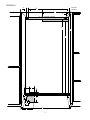
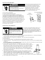
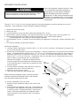
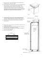
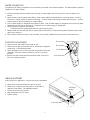
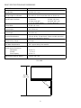
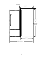
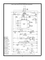
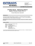
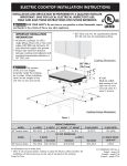
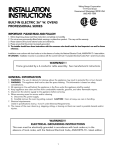
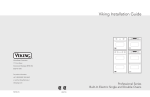
INSTALLATION
INSTRUCTIONS
VIKING RANGE CORPORATION
111 Front Street
Greenwood, Mississippi (MS) 38930 USA
(601) 455-1200
BUILT-IN BOTTOM MOUNT REFRIGERATOR
IMPORTANT - PLEASE READ AND FOLLOW
Make sure that incoming voltage is the same as unit rating. An electric rating plate specifying voltage, hertz, wattage, amps,
and phase is attached to the product.
To reduce the risk of fire, electric shock, or injury to persons, installation work and electrical wiring must be done by qualified
people in accordance with all applicable codes and standards, including fire-rated construction.
GENERAL INFORMATION
EXCESSIVE WEIGHT HAZARD
Use two or more people to move and install refrigerator.
Failure to follow this instruction can result in back or other injury.
Most of the refrigerator’s weight is at the top.
Extra care is needed when moving the
refrigerator to prevent tipping. Keep
cardboard shipping piece or plywood under
refrigerator until it is installed in the operating
position.
It is your responsibility to :
-comply with installation specifications and dimensions
-properly install refrigerator
-make sure that you have these materials which are necessary for proper installation:
1/4” (6 mm) copper tubing with shutoff valve
1/4” (6mm) compression fitting
-assure that floor will support refrigerator (more than 600 lbs. [272 kg.]), door panels and contents
-provide a properly grounded electrical outlet
-assure that location will permit appliance doors to open 90o minimum
CUTOUT DIMENSIONS
Diagram A
Description
Dimension
A
Width of lag bolt location
1” (2.54 cm)
B
Distance from right side of cutout
to left lag bolt location
32 9/16” (82.7 cm)
C
Width of receptacle location
27 1/2” (69.9 cm)
D
Distance from right side of cutout
to right lag bolt location
3 3/8” 8.6 cm)
Height to top of receptacle location and
bottom of 2” x 4” (5.1 cm x 10.2 cm)
mounting board (including cover plate)
80 1/2” (204.5 cm)
Height to bottom of receptacle
location (including cover plate)
75 1/8” (190.8 cm)
G
Height of cutout (min.)
84” (213.4 cm)
H
Depth of water line location
on side wall
1” (2.54 cm)
Position of water line location on
back wall
7 5/8” (19.4 cm)
Width of water line location on
back wall
6 3/4” (17.1 cm)
K
Height of water line location on side wall
5/8’ (1.6 cm)
L
Height of water line location on
back wall
3” (7.6 cm)
M
Depth of cutout (min.)
24” (61.0 cm)
N
Do not place water line in this location
3 5/8” (9.2 cm)
O
Width of water line location on floor
10 3/4” (27.3 cm)
P
Water valve location
See diagram
Q
Depth of water line location on floor
10 1/2” (26.7 cm)
R
Width of cutout (min.)
35 1/2” (90.2 cm)
E
F
I
J
Verify cutout depth is a minimum of 24” (61.0 cm) measuring from the rear of the cutout to the front. Minimum
refrigerator height is 83 1/4” (211.5 cm) with refrigerator adjusted to its lowest position. Maximum refrigerator height is
84 1/4” (214.0 cm) with refrigerator adjusted to its tallest position. Customize the installation if cutout height is more
than 84 1/4” (214.0 cm) and no cabinets are installed above the refrigerator. The electrical outlet must be installed
from 75 1/8” (190.8 cm) to 80 1/2” (204.5 cm) high and 0” to 21 1/2” (54.6 cm) from right side of cutout when facing
cutout.
2
DIAGRAM A
A
Lag bolt
Location
B
C
D
2” X 4” Mounting Board
Receptacle Location
E
G
F
H
I
J
L
K
Water
line entry
Q
M
P
R
N
O
3
ELECTRICAL REQUIREMENTS
ELECTRICAL SHOCK HAZARD
Electrically ground refrigerator.
Do Not use an extension cord.
Failure to follow these instructions could result
in death, fire, or electrical shock
It is the customer’s responsibility:
To contact a qualified electrical installer.
To assure that the electrical installation is adequate and in
conformance with the National Electrical Code, ANSI/NFPA 70latest edition or Canadian Electrical Code C22.1-1982 and C22.2
No. 01982 (or latest edition), and all local codes and ordinances.
120 volt, 60-Hz, 15 amp, fused, electrical supply is required. It is
recommended that a separate circuit serving only this appliance be
provided. This appliance is equipped with a power supply cord
having a 3-prong grounding plug. To minimize possible shock
hazard, the cord must be plugged into a mating 3-prong,
grounding-type wall receptacle.
If codes permit a separate grounding wire is used,
it is recommended that a qualified electrician
determine that the grounding path is adequate.
Do Not ground to a gas pipe. Check with a
qualified electrician if you are not sure the
appliance is properly grounded. Do Not have a
fuse in the neutral or grounding circuit.
3-prong
grounding plug
3-prong grounding-type
wall receptacle
grounding
plug
WATER SUPPLY REQUIREMENTS
ELECTRICAL SHOCK HAZARD
Some water may remain in line. Electric
drill must be grounded to prevent severe or
lethal shock if water is in line and enters drill
during use.
Use only 1/4” (6 mm) copper tubing for water line. Do
Not install copper tubing in area where temperatures
drop below 32 oF (0 oC). Before attaching copper tubing
to refrigerator, flush at least 2 quarts (1.9 L) of water
through the copper tubing and into a bucket to get rid of
any particles in the water line.
To calculate length of 1/4” (6mm) O.D. copper tubing needed:
1. Locate a vertical 1/2” (1.2 cm) to 1 1/4” (3.2 cm) COLD water line near refrigerator area. A horizontal COLD water
line can be used if directions in Step 4 are carefully followed.
2. Measure distance from cold water line to refrigerator. Add 24” (61 cm) to this measurement.
To rough in water line:
3. Turn OFF main water supply. Turn ON nearest faucet long enough to clear line of water.
4. Vertical cold water line: Use grounded electric drill or hand drill to drill 3/16” (4.5 cm) hole in an accessible location
in water line.
Horizontal cold water line: Use grounded electric drill or hand drill to drill 3/16” (4.5 cm) hole in the top of the water
line. This will keep sediment from collecting in valve.
5. Position washer over hole in water line. Turn saddle valve handle clockwise to expose
piercing lance a maximum of 3/16” (4.5 cm). Align piercing lance over hole in water line.
Place both halves of saddle valve bracket against water line. Turn saddle valve handle
clockwise until piercing lance enters hole in water line and is firmly seated. The saddle
valve is now in the closed position. Tighten packing nut. Evenly and firmly tighten
bracket screws so washer will make a water-tight connection. Do not overtighten screws;
copper tubing could be crushed.
6. Check that both ends of copper tubing are cut square. Slide compression nut and
sleeve onto copper tubing. Insert end of copper tubing completely into valve outlet.
Tighten compression nut to outlet with adjustable wrench. Do not overtighten.
7. Turn on main water supply. Check for leaks. Turn saddle valve counterclockwise and run
water through copper tubing into a bucket. Turn saddle valve handle clockwise to shut off water to copper tubing.
8. Route copper tubing into refrigerator area.
4
REFRIGERATOR INSTALLATION
EXCESSIVE WEIGHT HAZARD
Use two or more people to move and install refrigerator. Failure
to follow this instruction can result in back or other injury.
Most of the refrigerator’s weight is at the top. Extra
care is needed when moving the refrigerator to
prevent tipping. Do Not lower the refrigerator
against the shipping base when moving the
shipping base. Do Not remove protective film until
refrigerator is in operating position. All four leveling
legs must contact the floor to support and stabilize
the full weight.
The two 2” x 4” (5.1 cm x 10.2 cm ) mounting boards, for securing refrigerator to wall are attached to top rear of
refrigerator. Save cardboard to protect walls when installing refrigerator.
1.
2.
3.
4.
5.
Remove top and bottom strap.
Remove top cap.
Cut along dashes on carton rear with a utility knife extended 1/4” (.6 cm).
Remove carton, exterior packaging , and tape from lag screws. Do not remove nylon cord from power cord.
Remove shipping brackets from skid by removing 4 bolts with a 7/16” socket head screwdriver.
•Tilting refrigerator is not required to remove shipping brackets.
6. Strap refrigerator on cart. To prevent doors from opening, tilt refrigerator to handle side. Remove refrigerator from
skid.
7. To avoid floor damage, use protective material.
Securing the refrigerator
1. Locate and mark 2 wall studs to mount the first 2” x 4” (5.1 cm x 10.2 cm) board. See Diagram A on page 3. Do
not cover the electrical outlet.
2. Remove the mounting board from top rear of refrigerator. Locate and predrill 1/4” (.6 cm) holes in the mounting
board. Countersink the bolt heads into the 2” x 4” (5.1 cm x 10.2 cm) board using a wood bit. Bolt securely to
wall studs. Predrill 1/4” (.6 cm) holes in second 2” x 4” (5.1 cm x 10.2 cm) and countersink bolt heads. Attach
flush to first 2” x 4” (5.1 cm x 10.2 cm). If application does not have studs, such as a framed wall mount to the
wall not surface, use a minimum 1/4” (.6 cm) diameter
fasteners (not supplied). If cabinets are deeper than 24”,
mounting board must be shimmed and structurally secured Grill
to the mounting board. Longer bolts are required to shim Assembly
mounting board.
3. To avoid water line damage, verify water line is secure so
refrigerator does not run over the water line.
4. Repair any loose flooring in cutout.
5. Tape door and drawer shut with masking tape.
Screws
Before moving the refrigerator in place, confirm the finished
dimesions, electrical and plumbing locations, and minimum
door and drawer clearances are accurate.
6. Position refrigerator in front of cutout.
7. Remove top grill assembly by lifting in the center of the
assembly.
8. Verify operation by plugging power cord. Power switch will
be shipped in the ON position and showroom switch will be
in the OFF position. Display should flash. Press any key.
There is a 6 minute delay before the refrigerator starts.
Verify the position of each switch if there is no power to
refrigerator.
5
Showroom
Switch
Power
Switch
9. Pull end of nylon cord around refrigerator side level with top of
refrigerator door. Tape cord in place.
10. Roll refrigerator into cutout to within 3” (7.6 cm) of being flush with
kitchen cabinets. To avoid kitchen cabinet damage, place
cardboard between kitchen cabinets and refrigerator. Push
cardboard back with refrigerator and remove cardboard when
refrigerator is in place. Remove power cord slack by pulling nylon
cord straight out while pushing refrigerator completely into place.
Power and nylon cords will rest along refrigerator side.
Nylon
Cord
Wall Stud
11. Level refrigerator by turning front and rear leveling wheel bolts
clockwise to raise refrigerator and counterclockwise to lower
refrigerator. Rotate leveling feet until firmly in place against floor.
12. Align refrigerator with sides of kitchen cabinets by adjusting
leveling wheels.
Wall Board or Plaster
Access to
Lag Bolts
13. Remove the 8 screws holding the grill assembly. Remove the grill
assembly and set aside.
14. Screw lag bolts securely into mounting board using a magnetic 6”
extension socket. See Diagram A on page 3.
15. Push extra nylon cord in along side of refrigerator out of sight, or
cord can be flush refrigerator.
16. Replace the grill assembly.
Lag Bolts
Lag Bolt with
Extended Shaft
Leveling Wheel
Bolts
Leveling Feet
6
Mounting
Board
Lag Bolt
mounting
2 X 4 to
wall
WATER CONNECTION
The garden hose fitting, compression nut, and sleeve are located in the literature packet. The water filtration system is
shipped in the crisper drawer.
1. Flush air and impurities from water line by turning on water supply and running a pint or more of water into a
bucket.
2. Remove plastic cap from water valve fitting. Slide copper tubing through brass nut, and brass sleeve. Connect
brass nut on copper tubing to garden hose fitting. Connect garden hose fitting to water valve inlet port. Confirm
copper tubing is secure by pulling on copper tubing.
3. Turn on water supply to refrigerator and check for leaks. Turn off water supply to refrigerator and correct any leaks.
Repeat this process until no leaks exist. Completely turn on water supply to refrigerator.
4. Verify drain pain is installed and aligned.
•Drain pan must be pushed past and over initial stopping point.
5. Replace lower access panel with the air vents positioned at the top. Kitchen flooring must allow the lower access
panel to be removed.
6. After 24 hours checks for leaks. If unit is leaking, correct leaks. Repeat this process until no leaks are found.
120o position
DOOR STOP ADJUSTMENT
1. Remove center grill blade from the top air grill.
2. Remove top air grill by removing (4) 1/4” screws with a magnetic
screw driver. Pull assembly forward.
3. Open refrigerator door so door stop arm and shoulder screw are
accessible. Shoulder screws should be in 110o door opening
position.
4. Remove shoulder screw and place shoulder screw in the 90o or
120o door opening position.
110o position
90o position
Door Stop Arm
HINGE ADJUSTMENT
Verify proper door alignment. Only the top hinge is adjustable.
1. Remove the center grill blade from the top air grill.
2. Remove top air grill by removing (4) 1/4” screws with a
magnetic screw driver. Pull assembly forward.
3. Loosen the (4) top hinge screws.
4. Align refrigerator door by lifting.
5. Tighten screws.
Top Hinge
Screws
Top Hinge
7
BASIC SPECIFICATIONS AND DIMENSIONS
DESCRIPTION
VCBB360
Overall Width
36 5/16” (92.2 cm)
Overall Height from Bottom
Min. 83 1/4” (211.5 cm) to Max. 84 1/4” (214.0 cm)
Overall Depth from Rear
To side trim
To front of top grill
To end of handle bracket
Cutout Width
35 7/8” (91.1 cm)
Cutout Height
84” (213.4 cm)
Cutout Depth
24” (61.0 cm)
Electrical Requirements
120 volt, 60 Hz, 15 amp circuit; 3-wire cord with grounded
3-prong plug attached to product.
Maximum Amp Usage
8.2 amps
Inlet Water Requirements
1/4” copper tubing inlet waterline
Overall Interior Dimensions
•Refrigerator
•Freezer
•Total Capacity
15.2 cu. ft.
5.7 cu. ft.
20.9 cu. ft.
Approximate Shipping Weight
470 lbs. (211.5 kg)
22 3/16” (56.3 cm)
24 11/16” (62.7 cm)
27 1/4” (69.2 cm)
TOP VIEW
58 7/16”
(148.4 cm)
90 o
8
FRONT VIEW
36 5/16”
(92.2 cm)
Min. 83 1/4”
(211.5 cm)
51 7/16”
(130.7 cm)
to
Max. 84 1/4”
(214.0 cm)
23”
(58.4 cm)
9
SIDE VIEW
24 11/16”
(62.7 cm)
Min. 83 1/4”
(211.5 cm)
to
Max. 84 1/4”
(214.0 cm)
22 3/16”
(56.4 cm)
58 3/8” (148.3 cm)
10
WIRING DIAGRAM
BUILT-IN BOTTOM MOUNT REFRIGERATOR/FREEZER
WARNING:
ELECTRICAL
GROUNDING
INSTRUCTIONS
This appliance is
equipped with a
three prong
grounding plug for
your protection
against shock
hazard and should
be plugged
directly into a
properly grounded
three prong
receptacle. DO
NOT CUT OR
REMOVE THE
GROUNDING
REFER ONLY TO FEATURES WHICH ARE EQUIPPED WITH THIS UNIT.
11
F1692
Viking Range Corporation
111 Front Street
Greenwood, Mississippi (MS) 38930 USA • (601) 455-1200
Specifications subject to change without notice
(PS599VR)