1
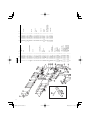
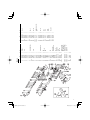
Impact Drill
Model VTP-16A • VTV-16
Handling instructions
VTV-16
Note:
Before using this Electric Power Tool, carefully read through these
HANDLING INSTRUCTIONS to ensure efficient, safe operation. It is
recommended that these INSTRUCTIONS be kept readily available as
an important reference when using this power tool.
000Book_VTP-16A.indb 1
2009/06/24 11:43:30
GENERAL SAFETY RULES
WARNING!
Read all instructions
Failure to follow all instructions listed below may result in
electric shock, fire and/or serious injury.
The term “power tool” in all of the warnings listed below
refers to your mains operated (corded) power tool or battery
operated (cordless) power tool.
SAVE THESE INSTRUCTIONS
1) Work area
a) Keep work area clean and well lit.
Cluttered and dark areas invite accidents.
b) Do not operate power tools in explosive
atmospheres, such as in the presence of
flammable liquids, gases or dust.
Power tools create sparks which may ignite the dust
of fumes.
c) Keep children and bystanders away while
operating a power tool.
Distractions can cause you to lose control.
2) Electrical safety
a) Power tool plugs must match the outlet.
Never modify the plug in any way.
Do not use any adapter plugs with earthed
(grounded) power tools.
Unmodified plugs and matching outlets will reduce
risk of electric shock.
b) Avoid body contact with earthed or grounded
surfaces such as pipes, radiators, ranges and
refrigerators.
There is an increased risk of electric shock if your
body is earthed or grounded.
c) Do not expose power tools to rain or wet
conditions.
Water entering a power tool will increase the risk of
electric shock.
d) Do not abuse the cord. Never use the cord for
carrying, pulling or unplugging the power tool.
Keep cord away from heat, oil, sharp edges or
moving parts.
Damaged or entangled cords increase the risk of
electric shock.
e) When operating a power tool outdoors, use an
extension cord suitable for outdoor use.
Use of a cord suitable for outdoor use reduces the
risk of electric shock.
f) Recommendation for the use of residual current
device with a rated residual current of 30mA or
less.
3) Personal safety
a) Stay alert, watch what you are doing and use
common sense when operating a power tool.
Do not use a power tool while you are tired
or under the influence of drugs, alcohol or
medication.
A moment of inattention while operating power tools
may result in serious personal injury.
b) Use safety equipment. Always wear eye
protection.
Safety equipment such as dust mask, non-skid
safety shoes, hard hat, or hearing protection used
for appropriate conditions will reduce personal
injuries.
c) Avoid accidental starting. Ensure the switch is
in the off position before plugging in.
Carrying power tools with your finger on the switch
or plugging in power tools that have the switch on
invites accidents.
2
000Book_VTP-16A.indb 2
d) Remove any adjusting key or wrench before
turning the power tool on.
A wrench or a key left attached to a rotating part of
the power tool may result in personal injury.
e) Do not overreach. Keep proper footing and
balance at all times.
This enables better control of the power tool in
unexpected situations.
f) Dress properly. Do not wear loose clothing or
jewellery. Keep your hair, clothing and gloves
away from moving parts.
Loose clothes, jewellery or long hair can be caught
in moving parts.
g) If devices are provided for the connection of
dust extraction and collection facilities, ensure
these are connected and properly used.
Use of these devices can reduce dust related
hazards.
4) Power tool use and care
a) Do not force the power tool. Use the correct
power tool for your application.
The correct power tool will do the job better and
safer at the rate for which it was designed.
b) Do not use the power tool if the switch does not
turn it on and off.
Any power tool that cannot be controlled with the
switch is dangerous and must be repaired.
c) Disconnect the plug from the power source
before making any adjustments, changing
accessories, or storing power tools.
Such preventive safety measures reduce the risk of
starting the power tool accidentally.
d) Store idle power tools out of the reach of
children and do not allow persons unfamiliar
with the power tool or these instructions to
operate the power tool.
Power tools are dangerous in the hands of untrained
users.
e) Maintain power tools. Check for misalignment
or binding of moving parts, breakage of parts
and any other condition that may affect the
power tools’ operation.
If damaged, have the power tool repaired
before use.
Many accidents are caused by poorly maintained
power tools.
f) Keep cutting tools sharp and clean.
Properly maintained cutting tools with sharp cutting
edges are less likely to bind and are easier to
control.
g) Use the power tool, accessories and tool bits
etc., in accordance with these instructions and
in the manner intended for the particular type
of power tool, taking into account the working
conditions and the work to be performed.
Use of the power tool for operations different from
intended could result in a hazardous situation.
5) Service
a) Have your power tool serviced by a qualified
repair person using only identical replacement
parts.
This will ensure that the safety of the power tool is
maintained.
PRECAUTION
Keep children and infirm persons away.
When not in use, tools should be stored out of reach
of children and infirm persons.
2009/06/24 11:43:31
IMPACT DRILL SAFETY WARNINGS
1. Wear ear protectors with impact drills.
Exposure to noise can cause hearing loss.
2. Use auxiliary handles supplied with the tool.
Loss of control can cause personal injury.
3. Before drilling into a wall, floor or ceiling, thoroughly
confirm that no items such as electric cables or conduits
are buried inside.
SPECIFICATIONS
Model
VTP-16A
Voltage (by areas)*
VTV-16
(110V, 115V, 120V, 127V, 220V, 230V, 240V)
Power input
800 W*
Speed change
1
2
3
4
No load speed
700/min
1400/min
0-700/min
0-1400/min
Capacity
Steel
16 mm
10 mm
16 mm
10 mm
Concrete
35 mm
16 mm
35 mm
16 mm
Weight (without cord)
3.8 kg
* Be sure to check the nameplate on product as it is subject to change by areas.
STANDARD ACCESSORIES
(1) Chuck wrench .............................................................. 1
(2) Side handle .................................................................. 1
(3) Depth stopper............................................................... 1
Standard accessories are subject to change without
notice.
OPTIONAL ACCESSORIES (sold separately)
○ Drill Bit for concrete
O.D
Length
6.5mm
100mm
Code No.
931851
8.0
100
931852
9.5
120
931853
10.0
120
931854
12.0
160
971704
13.0
160
931855
931776
14.3
160
16.0
160
971670
19.0
160
931856
Optional accessories are subject to change without notice.
APPLICATIONS
○ By combined actions of ROTATION and IMPACT:
Boring holes in hard materials (concrete, marble,
granite, tiles, etc.)
○ By ROTATIONAL action:
Boring holes in metal, wood and plastic.
PRIOR TO OPERATION
1. Power source
Ensure that the power source to be utilized conforms
to the power requirements specified on the product
nameplate.
000Book_VTP-16A.indb 3
2. Power switch
Ensure that the power switch is in the OFF position. If
the plug is connected to a receptacle while the power
switch is in the ON position, the power tool will start
operating immediately, inviting serious accident.
3. Extension cord
When the work area is removed from the power source,
use an extension cord of sufficient thickness and rated
capacity. The extension cord should be kept as short as
practicable.
4. Fitting the drill bit
Fit the drill bit into the chuck and use the chuck
wrench to secure it, tightening the chuck by each
of the three holes in turn.
5. Selecting the appropriate drill bit
○ When boring concrete or stone
Use the drill bits specified in the Optional Accessories.
○ When boring metal or plastic
Use an ordinary metalworking drill bit.
○ When boring wood
Use an ordinary woodworking drill bit.
However, when drilling 6.5 mm or smaller holes, use a
metalworking drill bit.
6. High-speed/Low-speed changeover:
Prior to changing speed, ensure that the switch is in
the OFF position, and the drill has come to a complete
stop. To change speed, depress the shift Iock and
slide it in the appropriate direction, as indicated by the
arrow in Fig. 1. The numeral “1” engraved in the drill
body denotes low speed, the numeral “2” denotes high
speed.
Gear cover
1 2
Shift lock
(push and slide)
Fig. 1
3
2009/06/24 11:43:31
7. IMPACT to ROTATION changeover: (Fig. 2)
The Impact Drill can be switched from IMPACT (impact
plus rotation) to ROTATION (rotation only) by simply
turning the change ring.
When boring concrete, stone, tile or similar hard
materials, turn the change ring fully clockwise. The drill
head impacts against the material while continuing to
rotate.
When boring metal, wood or plastic, turn the change
ring fully counterclockwise. The drill simply rotates as
an ordinary electric drill.
Change ring
Gear cover
Rotation
Rotation + impact
1 2
Fig. 2
CAUTION
Do not use the Impact Drill in the IMPACT function if the
material can be bored by rotation only. Such action will
not only reduce drill efficiency, but may also damage
the drill tip.
When changing over, ensure that the change ring is
turned as far as it will go.
8. Fixing the side handle.
Loosen the glip on the side handle, and attach the side
handle to the gear cover in a position convenient for
drilling. Match the projecting part of the handle to the
groove on the gear cover, and firmly tighten the glip.
To remove the side handle, loosen the glip, and rotate
the handle.
To attach a depth stopper on the side handle, insert
the stopper into the hexagon hole groove on the side
handle, adjust the position of the depth stopper in
accordance with the desired depth of the hole, and
firmly tighten the glip.
PRACTICAL HANDLING PROCEDURES
1. Pressure:
Drilling will NOT be accelerated by placing heavy
pressure on the drill. Such action will only result in a
damaged drill bit, decreased drilling efficiency and/or
shortened service life of the drill.
2. Using a large diameter drill bit:
The larger the drill bit diameter, the larger the reactive
force on your arm. Be careful not to lose control of the
drill because of this reactive force. To maintain firm
control, establish a good foothold, hold the drill tightly
with both hands, and ensure that the drill is vertical to
the material being drilled.
3. When drilling completely through the material:
When the drill bit bores completely through the material,
careless handling often results in a broken drill bit
or damage to the drill body itself due to the sudden
movement of the drill.
Always be alert and ready to release the pushing force
when drilling through the material.
4. Switch operation:
(1) VTP-16A:
By pulling the trigger switch and depressing the stopper,
the switch is held in the ON position for continuous
operation. To turn the drill OFF, pull the trigger switch
again and release.
(2) VTV-16:
The rotational speed of the drill bit can be controlled
by varying the amount that the trigger switch is pulled.
Speed is low when the trigger switch is pulled slightly
and increases as the switch is pulled more. Continuous
operation may be attained by pulling the trigger switch
and depressing the stopper. To turn the switch OFF, pull
the trigger switch again to disengage the stopper, and
release the trigger switch to its original position.
5. Precautions on boring
The drill may become overheated during operation;
however, it is sufficiently operable. Do not cool the drill
bit in water or oil.
6. Caution concerning immediately after use
Immediately after use, while it is still revolving, if the Drill
is placed on a location where considerable ground chips
and dust have accumulated, dust may occasionally be
absorbed into the Drill mechanism.
Always pay attention to this possibility.
MAINTENANCE AND INSPECTION
1. Inspection the drill bit
Continued use of a worn and/or damaged drill bit will
result in reduced drilling efficiency and may seriously
overload the drill motor. Inspect the drill bit often and
replace it with a new bit as necessary.
2. Inspecting the mounting screws
Regularly inspect all mounting screws and ensure that
they are properly tightened. Should any of the screws
be loose, retighten them immediately. Failure to do so
could result in serious hazard.
3. Inspecting the carbon brushes (Fig. 3)
The Motor employs carbon brushes which are
consumable parts. When they become worn to or near
the “wear limit”, it could result in motor trouble. When an
auto-stop carbon brush is equipped, the motor will stop
automatically.
At that time, replace both carbon brushes with new ones
which have the same carbon brush Numbers shown in
the figure. In addition, always keep carbon brushes
clean and ensure that they slide freely within the brush
holders.
Wear limit
b mm No. of carbon brush
a mm
No. of
carbon
brush
a
b
43
17
6
Usual carbon
brush
73
17
7
Auto-stop
carbon brush
Fig. 3
4
000Book_VTP-16A.indb 4
2009/06/24 11:43:31
4. Replacing carbon brushes
Disassemble the brush caps with a slotted-head
screwdriver. The carbon brushes can then be easily
removed.
5. Maintenance of the motor
The motor unit winding is the very “heart” of the power
tool. Exercise due care to ensure the winding does not
become damaged and/or wet with oil or water.
6. Replacing supply cord
If the supply cord of Tool is damaged, the Tool must be
returned to Hitachi Authorized Service Center for the
cord to be replaced.
7. Service parts list
A: Item No.
B: Code No.
C: No. Used
D: Remarks
CAUTION
Repair, modification and inspection of Hitachi Power
Tools must be carried out by an Authorized Service
Center.
This Parts List will be helpful if presented with the power
tool to the Authorized Service Center when requesting
repair or other maintenance.
In the operation and maintenance of power tools, the
safety regulations and standards prescribed in each
country must be observed.
MODIFICATIONS
Hitachi Power Tools are constantly being improved
and modified to incorporate the latest technological
advancements.
Accordingly, some parts (i.e. code numbers and/or
design) may be changed without prior notice.
NOTE
Due to HITACHI’s continuing program of research and
development, the specifications herein are subject to
change without prior notice.
5
000Book_VTP-16A.indb 5
2009/06/24 11:43:31
6
000Book_VTP-16A.indb 6
2009/06/24 11:43:31
B
930733
950284
981566
876319
981568
971657
939556
981572
6003VV
981592
981571
980717
971736
939543
981564
971661
981573
608VVM
981570
949454
955912
942864
981574
981575
981576
981577
981569
981581
609VVM
981585
981588
981611C
981611E
981611F
991007
930703
981610C
981610E
981610F
981610G
981610H
981610J
––––––
A
1
2
3
4
5
6
7
8
9
10A
12
13
14
15
16
17
18
19
20
21
22
23
24
25
26
27A
28
29
30
31
32
33-1
33-2
33-3
35A
36
37-1
37-2
37-3
37-4
37-5
37-6
39
VTP-16A
1
1
1
1
C
1
1
1
1
1
1
1
1
1
1
1
1
1
1
1
1
1
3
1
6
4
1
1
1
1
1
1
1
1
1
1
1
1
1
2
2
1
1
1
110V-127V “36”
220V-230V “36”
240V “36”
220V-230V “36”
“FRA, ITA, GBR”
240V “36” “AUS”
110V “36” “GBR”
M5 × 16
110V-127V
220V-230V
240V
D5 × 60
“19, 30-32”
609VVC2PS2L
M5
M5
D5 × 45
M5
608VVC2PS2L
S-38
6003VVCMPS2L
S-14
D
13G
16WL “1”
A
40
41A
42
43
44
45A
46
47A
48
49
50
51
52
53
54
55
56
57
58
59
60-1
60-2
61
63
63A
500
501
502
503
B
961781
999073
981586
981560
981562
984367
946362
994273
930153
971667Z
949365
957561
959140
956384
949423
981578
981373
938108
954004
960266
953327
938051
––––––
981500
986277
931844
981579
981580
983987
C
2
2
2
1
1
1
1
1
1
1
2
1
1
5
6
1
2
1
2
1
1
1
1
1
1
1
1
1
1
“502, 503”
“EUROPE, AUS”
“NZL, GBR, SAF”
D8.8
D10.1
D4 × 16
D4 × 20
M4
M4 × 5
“42, 50”
D
7
000Book_VTP-16A.indb 7
2009/06/24 11:43:31
B
930733
950284
981566
876319
981568
971657
939556
981572
6003VV
981592
981571
980717
971736
939543
981564
971661
981573
608VVM
981570
949424
983981
942864
981574
981575
981576
981577
981569
981581
609VVM
981585
981588
981611E
981611F
991007
930703
971720G
981610H
980945E
980945F
––––––
961781
999073
A
1
2
3
4
5
6
7
8
9
10A
12
13
14
15
16
17
18
19
20
21
22
23
24
25
26
27A
28
29
30
31
32
33-1
33-2
35A
36
37A-1
37A-2
37A-3
37A-4
38
39
40A
VTV-16
1
1
1
1
2
2
C
1
1
1
1
1
1
1
1
1
1
1
1
1
1
1
1
1
3
1
4
4
1
1
1
1
1
1
1
1
1
3
1
1
2
2
1
220V “36” “SAF,
GBR, HOL, AUT,
SUI, FRG, FRA”
240V “36” “AUS”
220V-230V “36”
240V “36”
M5 × 16
220V-230V
240V
D5 × 60
“19, 30-32”
609VVC2PS2L
M5
M5
D5 × 45
M5
608VVC2PS2L
S-38
6003VVCMPS2L
S-14
D
13G
16WL “1”
B
981586
982320Z
981562
984367
946362
994273
930153
318344
949365
957561
959141
982095
324722
324901
938108
981373
930446
960266
930793
953327
938051
––––––
986277
955908
931844
981579
981580
983987
A
41
42
43
44A
45
46
47
48A
49
50
51
52
53A-1
53A-2
54
57
58
59
60
61-1
61-2
62
63
64
500
501
502
503
1
1
2
1
1
1
1
1
1
1
1
1
1
1
C
2
1
1
1
1
1
1
1
2
1
1
5
1
1
“502, 503”
“SUI”
“NZL”
D8.8
D10.1
D4 × 16
“GBR(230V), SAF,
SUI”
D4 × 20
M4 × 5
“41, 49”
D
Hitachi Koki Co., Ltd.
Shinagawa Intercity Tower A, 15-1, Konan 2-chome,
Minato-ku, Tokyo, Japan
911
Code No. C99013611 N
Printed in Japan
000Book_VTP-16A.indb 8
2009/06/24 11:43:31