1
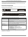
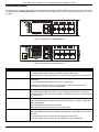
Hardware Installation Guide
Product Model: DXS-3600 Series
Layer 2/3 Managed 10GbE Switch
Release: 1.10
DXS-3600 Series 10GbE Layer 2/3 Switch Hardware Installation Guide
Information in this document is subject to change without notice. Reproduction of this document in any manner whatsoever, without the written
permission of the D-Link Corporation, is strictly forbidden.
Trademarks used in this text: D-Link and the D-Link logo are trademarks of the D-Link Corporation; Microsoft and Windows are registered
trademarks of the Microsoft Corporation.
Other trademarks and trade names may be used in this document to refer to either as the entities claiming the marks and the names or their
products. D-Link Corporation disclaims any proprietary interest in trademarks and trade names other than its own.
© 2012 D-Link Corporation. All rights reserved.
August, 2012. P/N 651XS3632010G
FCC Warning
This equipment has been tested and found to comply with the limits for a Class A digital device, pursuant to Part 15 of
the FCC Rules. These limits are designed to provide reasonable protection against harmful interference when the
equipment is operating in a commercial environment. This equipment generates, uses, and can radiate radio frequency
energy and, if not installed and used in accordance with this manual, may cause harmful interference to radio
communications. Operation of this equipment in a residential area is likely to cause harmful interference in which case
the user will be required to correct the interference at his expense.
CE Mark Warning
This is a Class A product. In a domestic environment, this product may cause radio interference in which case the user
may be required to take adequate measures.
Warnung!
Dies ist ein Produkt der Klasse A. Im Wohnbereich kann dieses Produkt Funkstoerungen verursachen. In diesem Fall
kann vom Benutzer verlangt werden, angemessene Massnahmen zu ergreifen.
Precaución!
Este es un producto de Clase A. En un entorno doméstico, puede causar interferencias de radio, en cuyo case, puede
requerirse al usuario para que adopte las medidas adecuadas.
Attention!
Ceci est un produit de classe A. Dans un environnement domestique, ce produit pourrait causer des interférences
radio, auquel cas l`utilisateur devrait prendre les mesures adéquates.
Attenzione!
Il presente prodotto appartiene alla classe A. Se utilizzato in ambiente domestico il prodotto può causare interferenze
radio, nel cui caso è possibile che l`utente debba assumere provvedimenti adeguati.
VCCI Warning
この装置は、クラス A 情報技術装置です。この装置を家庭環境で使用すると電波妨害を引き起こすことがあります。
この場合には使用者が適切な対策を講ずるよう要求されることがあります。VCCI-A
i
DXS-3600 Series 10GbE Layer 2/3 Switch Hardware Installation Guide
Intended Readers
The DXS-3600 Series Hardware Installation Guide contains detailed information about the hardware specifications
of a switch in this series. It also contains brief information on how to configure and manage a switch in this series. This
manual is intended for advanced level users that are familiar with network management concepts and terminology. For
all practical reasons the DXS-3600-32S and DXS-3600-16S will simply be referred to as the switch throughout this
manual.
Typographical Conventions
Convention
Description
[]
This convention is generally used in CLI commands. Square brackets indicate an
optional entry. For example: [copy | paste] means that optionally you can type copy
or you can type paste. Do not type the brackets.
Bold Font
This font is generally used to put emphasis on a key subject in a sentence throughout this manual. This font is also used to represent the physical CLI command used
when explaining a topic.
Boldface Typewriter Font
This font is used to indicate CLI command examples used in this document.
Initial capital letter
The use of initial capital letters indicates that a referral to a specific name was made.
This will be seen a lot when referring to protocols, standards, keyboard keys, and
when we refer to the ‘Switch’ as a generic name for all switches with in the series.
For example: Click Enter.
Menu Name > Menu Option
This convention indicates the referral to a menu structure found in the Web User
Interface of this Switch. For example: Device > Port > Port Properties means the
Port Properties menu option under the Port menu option that is located under the
Device menu.
Notes, Notices, and Cautions
NOTE: A note indicates important information that helps you make better use of your device
NOTICE: A notice indicates either potential damage to hardware or loss of data and tells you how to
avoid the problem
CAUTION: A caution indicates a potential for property damage, personal injury, or death.
Safety Instructions
Please pay careful attention to the following safety guidelines to ensure your own personal safety and to help protect
your system from potential damage.
ii
DXS-3600 Series 10GbE Layer 2/3 Switch Hardware Installation Guide
Safety Cautions
To greatly reduce the risk of physical injury, electrical shock, fire, and damage to equipment, observe the following
precautions.
Observe and follow service markings.
• Do not attempt to service any product, except when it is explained in the system’s documentation.
• Opening or removing covers that are marked with this (
) symbol may expose the user to electrical shock.
• Only a trained service technician should service components inside these compartments.
If any of the following conditions occur, unplug the product from the electrical outlet immediately and replace the part or
contact your trained service provider:
• Damage to the power cable, extension cable, or plug.
• An object has fallen into the product.
• The product has been exposed to water.
• The product has been dropped or damaged.
• The product does not operate correctly when the operating instructions are correctly followed.
General safety cautions:
• Keep the system away from radiators and heat sources. Also, do not block cooling vents.
• Do not spill food or liquids on system components, and never operate the product in a wet environment. If the
system gets wet contact your trained service provider.
• Do not push any objects into the openings of the system. Doing so can cause fire or electric shock by shorting out
interior components.
• Only use this product with approved equipment.
• Allow the product to cool before removing the cover or touching internal components.
• Operate the product only from the type of external power source indicated on the electrical ratings label. If unsure of
the type of power source required, consult your service provider or local power company.
• Be sure that attached devices are electrically rated to operate with the power available in your location.
• Use only approved power cable(s). If you have not been provided with a power cable for your system or for any ACpowered option intended for your system, purchase a power cable that is approved for use in your country. The
power cable must be rated for the product and for the voltage and current marked on the product's electrical ratings
label. The voltage and current rating of the cable should be greater than the ratings marked on the product.
• To help prevent electric shock, plug the system and peripheral power cables into properly grounded electrical
outlets. These cables are equipped with three-prong plugs to help ensure proper grounding. Do not use adapter
plugs or remove the grounding prong from a cable. If using an extension cable is necessary, use a 3-wire cable with
properly grounded plugs.
• Observe the extension cable and power strip ratings. Make sure that the total ampere rating of all products plugged
into the extension cable or power strip does not exceed 80 percent of the ampere ratings limit for the extension
cable or power strip.
• To help protect the system from sudden, transient increases and decreases in electrical power, use a surge
suppressor, line conditioner, or uninterruptible power supply (UPS).
• Position system cables and power cables carefully. Route cables so that they cannot be stepped on or tripped over.
Be sure that nothing rests on any cables.
• Do not modify power cables or plugs. Consult a licensed electrician or your power company for site modifications.
Always follow your local or national wiring rules.
When connecting or disconnecting power to and from hot-pluggable power supplies, observe the following guidelines:
• Install the power supply before connecting the power cable to the power supply.
• Unplug the power cable before removing the power supply.
• If the system has multiple sources of power, disconnect power from the system by unplugging all power cables from
the power supplies.
• Move products with care and ensure that all casters and stabilizers are firmly connected to the system. Avoid
sudden stops and uneven surfaces.
To help avoid damage to the system, be sure that the voltage selection switch, on the power supply, is set to match the
power available at the switch’s location:
iii
DXS-3600 Series 10GbE Layer 2/3 Switch Hardware Installation Guide
• 115V/60Hz is used mostly in North and South America as well as Far Eastern countries like as South Korea and
Taiwan
• 100V/50Hz is used mostly in Eastern Japan and 100V/60Hz in Western Japan
• 230V/50Hz is used mostly in Europe, the Middle East, Africa and the Far East
General Precautions for Rack-Mountable Products
Please pay careful attention to the following precautions concerning rack stability and safety. Systems are considered
to be components in a rack. Thus, a component refers to any system, as well as to various peripherals or supporting
hardware.
CAUTION: Installing systems in a rack without the front and side stabilizers installed could cause the
rack to tip over, potentially resulting in serious injury. After installing system/components in a rack,
never pull more than one component out of the rack on its slide assemblies at one time. The weight
of more than one extended component could cause the rack to tip over and may result in serious
injury.
• Before working on the rack, make sure that the stabilizers are secured to the rack, extended to the floor, and that the
full weight of the rack rests on the floor. Install front and side stabilizers on a single rack or front stabilizers for joined
multiple racks before working on the rack.
• Always load the rack from the bottom up, and load the heaviest item in the rack first.
• Make sure that the rack is level and stable before extending a component from the rack.
• Use caution when pressing the component rail release latches and sliding a component into or out of a rack; the
slide rails can pinch your fingers.
• After a component is inserted into the rack, carefully extend the rail into a locking position, and then slide the
component into the rack.
• Do not overload the AC supply branch circuit that provides power to the rack. The total rack load should not exceed
80 percent of the branch circuit rating.
• Ensure that proper airflow is provided to components in the rack.
• Do not step on or stand on any component when servicing other components in a rack.
CAUTION: Never defeat the ground conductor or operate the equipment in the absence of a suitably
installed ground conductor. Contact the appropriate electrical inspection authority or an electrician if
uncertain that suitable grounding is available.
CAUTION: The system chassis must be positively grounded to the rack cabinet frame. Do not
attempt to connect power to the system until grounding cables are connected. Completed power and
safety ground wiring must be inspected by a qualified electrical inspector. An energy hazard will exist
if the safety ground cable is omitted or disconnected.
Protecting Against Electrostatic Discharge
Static electricity can harm delicate components inside the system. To prevent static damage, discharge static electricity
from your body before touching any of the electronic components, such as the microprocessor. This can be done by
periodically touching an unpainted metal surface on the chassis.
The following steps can also be taken prevent damage from electrostatic discharge (ESD):
• When unpacking a static-sensitive component from its shipping carton, do not remove the component from the
antistatic packing material until ready to install the component in the system. Just before unwrapping the antistatic
packaging, be sure to discharge static electricity from your body.
• When transporting a sensitive component, first place it in an antistatic container or packaging.
• Handle all sensitive components in a static-safe area. If possible, use antistatic floor pads, workbench pads and an
antistatic grounding strap.
iv
DXS-3600 Series 10GbE Layer 2/3 Switch Hardware Installation Guide
Table of Contents
Intended Readers . . . . . . . . . . . . . . . . . . . . . . . . . . . . . . . . . . . . . . . . . . . . . . . . . . . . . . . . . . . . . . . . . . . . . . . . ii
Typographical Conventions. . . . . . . . . . . . . . . . . . . . . . . . . . . . . . . . . . . . . . . . . . . . . . . . . . . . . . . . . . . . . . . . . ii
Notes, Notices, and Cautions . . . . . . . . . . . . . . . . . . . . . . . . . . . . . . . . . . . . . . . . . . . . . . . . . . . . . . . . . . . . . . . ii
Safety Instructions. . . . . . . . . . . . . . . . . . . . . . . . . . . . . . . . . . . . . . . . . . . . . . . . . . . . . . . . . . . . . . . . . . . . . . . . ii
Safety Cautions . . . . . . . . . . . . . . . . . . . . . . . . . . . . . . . . . . . . . . . . . . . . . . . . . . . . . . . . . . . . . . . . . . . . . . . . iii
General Precautions for Rack-Mountable Products . . . . . . . . . . . . . . . . . . . . . . . . . . . . . . . . . . . . . . . . . . . . . . iv
Protecting Against Electrostatic Discharge . . . . . . . . . . . . . . . . . . . . . . . . . . . . . . . . . . . . . . . . . . . . . . . . . . . . . iv
Introduction. . . . . . . . . . . . . . . . . . . . . . . . . . . . . . . . . . . . . . . . . . . . . . . . . . . . . . . . . . . . . . . . . . . . . . . . . . . . . . . 1
Switch Description. . . . . . . . . . . . . . . . . . . . . . . . . . . . . . . . . . . . . . . . . . . . . . . . . . . . . . . . . . . . . . . . . . . . . . . . 1
Package Contents . . . . . . . . . . . . . . . . . . . . . . . . . . . . . . . . . . . . . . . . . . . . . . . . . . . . . . . . . . . . . . . . . . . . . . . . 1
Features . . . . . . . . . . . . . . . . . . . . . . . . . . . . . . . . . . . . . . . . . . . . . . . . . . . . . . . . . . . . . . . . . . . . . . . . . . . . . . . 2
Front Panel Components . . . . . . . . . . . . . . . . . . . . . . . . . . . . . . . . . . . . . . . . . . . . . . . . . . . . . . . . . . . . . . . . . . 3
LED Indicators . . . . . . . . . . . . . . . . . . . . . . . . . . . . . . . . . . . . . . . . . . . . . . . . . . . . . . . . . . . . . . . . . . . . . . . . . 4
Rear Panel Description . . . . . . . . . . . . . . . . . . . . . . . . . . . . . . . . . . . . . . . . . . . . . . . . . . . . . . . . . . . . . . . . . . . . 5
Power Supply Module. . . . . . . . . . . . . . . . . . . . . . . . . . . . . . . . . . . . . . . . . . . . . . . . . . . . . . . . . . . . . . . . . . . . 6
Fan Module. . . . . . . . . . . . . . . . . . . . . . . . . . . . . . . . . . . . . . . . . . . . . . . . . . . . . . . . . . . . . . . . . . . . . . . . . . . . 6
Side Panel Description . . . . . . . . . . . . . . . . . . . . . . . . . . . . . . . . . . . . . . . . . . . . . . . . . . . . . . . . . . . . . . . . . . . . 6
Installation. . . . . . . . . . . . . . . . . . . . . . . . . . . . . . . . . . . . . . . . . . . . . . . . . . . . . . . . . . . . . . . . . . . . . . . . . . . . . . . . 7
Installation Guidelines . . . . . . . . . . . . . . . . . . . . . . . . . . . . . . . . . . . . . . . . . . . . . . . . . . . . . . . . . . . . . . . . . . . . . 7
Installing the Switch without a Rack . . . . . . . . . . . . . . . . . . . . . . . . . . . . . . . . . . . . . . . . . . . . . . . . . . . . . . . . . . 7
Installing the Switch into a Rack . . . . . . . . . . . . . . . . . . . . . . . . . . . . . . . . . . . . . . . . . . . . . . . . . . . . . . . . . . . . . 8
Installing Transceivers into the Transceiver Ports. . . . . . . . . . . . . . . . . . . . . . . . . . . . . . . . . . . . . . . . . . . . . . . . 9
Installing Power Modules into the Power Module Ports . . . . . . . . . . . . . . . . . . . . . . . . . . . . . . . . . . . . . . . . . . . 9
Installing an AC Power Module. . . . . . . . . . . . . . . . . . . . . . . . . . . . . . . . . . . . . . . . . . . . . . . . . . . . . . . . . . . . 10
Installing a DC Power Module . . . . . . . . . . . . . . . . . . . . . . . . . . . . . . . . . . . . . . . . . . . . . . . . . . . . . . . . . . . . 11
Installing Fan Modules into the Fan Module Ports . . . . . . . . . . . . . . . . . . . . . . . . . . . . . . . . . . . . . . . . . . . . . . 12
Switch Connections . . . . . . . . . . . . . . . . . . . . . . . . . . . . . . . . . . . . . . . . . . . . . . . . . . . . . . . . . . . . . . . . . . . . . . . 13
Switch to an End Node . . . . . . . . . . . . . . . . . . . . . . . . . . . . . . . . . . . . . . . . . . . . . . . . . . . . . . . . . . . . . . . . . . . 13
Switch to another Switch . . . . . . . . . . . . . . . . . . . . . . . . . . . . . . . . . . . . . . . . . . . . . . . . . . . . . . . . . . . . . . . . . . 13
Switch to a Server . . . . . . . . . . . . . . . . . . . . . . . . . . . . . . . . . . . . . . . . . . . . . . . . . . . . . . . . . . . . . . . . . . . . . . . 14
Switch Management . . . . . . . . . . . . . . . . . . . . . . . . . . . . . . . . . . . . . . . . . . . . . . . . . . . . . . . . . . . . . . . . . . . . . . . 15
Management Options . . . . . . . . . . . . . . . . . . . . . . . . . . . . . . . . . . . . . . . . . . . . . . . . . . . . . . . . . . . . . . . . . . . . 15
Connecting to the Console Port . . . . . . . . . . . . . . . . . . . . . . . . . . . . . . . . . . . . . . . . . . . . . . . . . . . . . . . . . . . . 15
Connecting to the Switch for the first time . . . . . . . . . . . . . . . . . . . . . . . . . . . . . . . . . . . . . . . . . . . . . . . . . . . 17
Creating a User Account. . . . . . . . . . . . . . . . . . . . . . . . . . . . . . . . . . . . . . . . . . . . . . . . . . . . . . . . . . . . . . . . . 17
Configuring the IP Address. . . . . . . . . . . . . . . . . . . . . . . . . . . . . . . . . . . . . . . . . . . . . . . . . . . . . . . . . . . . . . . 18
Connecting using SNMP . . . . . . . . . . . . . . . . . . . . . . . . . . . . . . . . . . . . . . . . . . . . . . . . . . . . . . . . . . . . . . . . . . 19
Traps. . . . . . . . . . . . . . . . . . . . . . . . . . . . . . . . . . . . . . . . . . . . . . . . . . . . . . . . . . . . . . . . . . . . . . . . . . . . . . . . 20
Management Information Base (MIB). . . . . . . . . . . . . . . . . . . . . . . . . . . . . . . . . . . . . . . . . . . . . . . . . . . . . . . 21
Connecting using the Web User Interface. . . . . . . . . . . . . . . . . . . . . . . . . . . . . . . . . . . . . . . . . . . . . . . . . . . . . 21
Logging onto the Web Manager . . . . . . . . . . . . . . . . . . . . . . . . . . . . . . . . . . . . . . . . . . . . . . . . . . . . . . . . . . . 21
Areas of the User Interface. . . . . . . . . . . . . . . . . . . . . . . . . . . . . . . . . . . . . . . . . . . . . . . . . . . . . . . . . . . . . . . 22
Appendix A - Technical Specifications . . . . . . . . . . . . . . . . . . . . . . . . . . . . . . . . . . . . . . . . . . . . . . . . . . . . . . . 23
Appendix B - Cables and Connectors . . . . . . . . . . . . . . . . . . . . . . . . . . . . . . . . . . . . . . . . . . . . . . . . . . . . . . . . 27
Ethernet Cable . . . . . . . . . . . . . . . . . . . . . . . . . . . . . . . . . . . . . . . . . . . . . . . . . . . . . . . . . . . . . . . . . . . . . . . . . 27
Console Cable. . . . . . . . . . . . . . . . . . . . . . . . . . . . . . . . . . . . . . . . . . . . . . . . . . . . . . . . . . . . . . . . . . . . . . . . . . 28
Warranty . . . . . . . . . . . . . . . . . . . . . . . . . . . . . . . . . . . . . . . . . . . . . . . . . . . . . . . . . . . . . . . . . . . . . . . . . . . . . . . . 29
Technical Support . . . . . . . . . . . . . . . . . . . . . . . . . . . . . . . . . . . . . . . . . . . . . . . . . . . . . . . . . . . . . . . . . . . . . . . . 30
DXS-3600 Series 10GbE Layer 2/3 Switch Hardware Installation Guide
Introduction
Switch Description
Package Contents
Features
Front Panel Components
Rear Panel Description
Side Panel Description
Switch Description
The DXS-3600 Series switch is a switch designed to meet the needs and requirements Data Center networks that
require Top-of-Rack access switches and Enterprise/Campus aggregation switches, where low latency and high
bandwidth capacity is essential. The switch is a fully managed Layer 2, for Standard Image (SI) mode, and Layer 3, for
Enhanced Image (EI) mode, switch. With support for IPv4 static and dynamic routing and a plethora of advanced
security and enhanced QoS features, the switch future proofs your network and provides a seamless migration path to
IPv6.
The DXS-3600 Series, running in the Enhanced Image (EI) mode, is a high-performance Layer 3 switch that provides
advanced Layer 3 routing features such as RIP, OSPF, BGP4, VRRP, up to 5 IP addresses per VLAN, and floating
static routes. Multipath routing (which is the method of establishing multiple paths between given source-destination
nodes within a network) are also features supported on the switch. These added routing features provide redundancy,
load balancing, and improved network utilization for the network.
The DXS-3600 Series incorporates an advanced portfolio of security features designed to protect your network from
malicious attacks. SSH encrypted management guarantee secure private configuration and monitoring when using the
Graphical User Interface (GUI) and Command Line (CLI). IEEE 802.1X ports and MAC-based authentication help
provide added network security by requiring all users attempting to connect to your network to provide a username and
password. This username and password must then be authenticated on a RADIUS or TACACS+ server, ensuring only
authorized users have access to the network. Access Control Lists (ACL) based on Layers 2/3/4, Rate Limiting, and
Guest VLANs provide even more control over what and how users access the network.
The DXS-3600 Series facilitates the deployment of enterprise applications such as VoIP, streaming media, and
multicast content delivery such as IP video conferencing and software deployment with enhanced enterprise features
such as L2/L3/L4 QoS, IGMP and MLD snooping, 802.1w Rapid Spanning Tree, 802.1s Multiple Spanning Tree group,
802.3ad Link Aggregation, and 802.1Q VLANs.
In the DXS-3600 Series the following switches exist:
• DXS-3600-16S - which includes eight 10 Gigabit SFP+ ports and one open expansion module slot.
• DXS-3600-32S - which includes twenty-four 10 Gigabit SFP+ ports and one open expansion module slot.
Package Contents
Open the shipping carton of the Switch and carefully unpack its contents. The carton should contain the following
items:
• One DXS-3600 Series switch.
• One Quick Installation Guide.
• One AC power cord.
• One AC power supply module.
• Three Fan modules.
• One RJ-45 to RS-232 console cable.
• One rack mounting kit (two brackets and screws).
• Four rubber feet with adhesive backing.
• One CD containing the Web UI Reference Guide, CLI Reference Guide, and D-View module.
1
DXS-3600 Series 10GbE Layer 2/3 Switch Hardware Installation Guide
If any item is missing or damaged, please contact your local D-Link reseller for replacement.
Features
This switch is action packed with an abundance of networking features that span inside and outside of the traditional
Layer 3 framework. The list below highlights the significant protocols and features supported by this switch.
Features that can be found on this switch are:
•
•
• D-Link License Management System (DLMS)
• IP Interface
• Jumbo Frames (12 KBytes)
• Spanning Tree Protocol (STP, RSTP, MSTP)
• Port Mirroring
• Link Aggregation
• Priority-based Flow Control (PFC)
• Layer 2 Multicast Filtering
• IGMP Snooping (Versions 1, 2, 3)
• IGMP and MLD Proxy
• Secure Shell (SSH)
• 802.1Q VLAN
• Port-based VLAN
• MAC-based VLAN
• VLAN Trunking
• Private VLAN
• Subnet-based VLAN
• Q-in-Q
• VLAN Translation
• Quality of Service (QoS)
• Queue Handling
• Class of Service (CoS)
• Bandwidth Control
• Three Color Marker
• Congestion Control
• Access Control List (ACL)
• Time Based ACL
• Traffic Segmentation
• Port Security
• Broadcast/Multicast/DLF Storm Control
• BPDU Attack Protection
• DoS Prevention
• 802.1X Network Access Control
• Access Authentication Control (AAA)
• Guest VLAN
• User Account Privilege for Management Access
• RADIUS Accounting
• Address Resolution Protocol (ARP)
• Link Layer Discovery Protocol (LLDP)
• Static Routing
• Web-based Graphical User Interface (Web GUI)
• Command Line Interface (CLI)
• Traffic Monitoring
• Telnet Server and Client
• TFTP Client
• FTP Client
• Simple Network Management Protocol (SNMP)
• System Log
• DHCP Server and Client
• CPU Monitoring
• DHCP Relay
• Trap/ Log Severity Control
• Multiple Image and Configuration
• Flash File System (FFS)
• Password Recovery and Encryption
• Simple Network Time Protocol (SNTP)
• Debug Command
• Traceroute and Ping
• DNS Resolver and Relay
• Virtual Router Redundancy Protocol (VRRP)
• Routing Information Protocol (RIP)
• Open Shortest Path First (OSPF)
• Border Gateway Protocol (BGP)
• Multicast Listener Discovery (MLD)
• Route Preference and Distribution
• Internet Group Management Protocol (IGMP)
• Multicast Duplication
• Protocol Independent Multicast (DM, SM, SSM, SparseDense)
• Distance Vector Multicast Routing Protocol (DVMRP)
2
DXS-3600 Series 10GbE Layer 2/3 Switch Hardware Installation Guide
•
•
• Management Information Base (MIBs) for MIBII, Bridge MIB, SNMPv2 MIB, RMON MIB, RMONv2 MIB, Ether-like
MIB, 802.3 MAU MIB, 802.1p MIB, IF MIB, RADIUS Authentication Client MIB, IGMPv3 MIB, RIPv2 MIB, IP Forwarding Table MIB (CIDR), IPv4 Multicast Routing MIB, PIM MIB for IPv4, RADIUS Accounting Client MIB, Ping MIB,
Trace out MIB, OSPFv2 MIB, VRRP MIB, Private MIB, Entity MIB.
Front Panel Components
The front panel of the switch consists of LED indicators, an SD card slot, an Out-Of-Band Management port (MGMT), a
Console port, SFP+ ports and an open module slot.
Figure 1-1 Front panel view of the DXS-3600-16S
Figure 1-2 Front panel view of the DXS-3600-32S
Ports that can be found on the front panel of this switch are listed in the table below.
Port
Description
SD Card Slot
This port can be used to insert an external SD memory card. The maximum capacity
SD card that can be inserted into this port is 32Gb.
Management port (MGMT)
This port is a 10/100/1000Mbps Ethernet port with an RJ-45 connection. This OutOf-Band management port that can be used to configure this switch without being
connected to the network.
Console port
This port is an RJ-45 connection port that can be used to connect to the Command
Line Interface (CLI) of this switch for configuration, management and monitoring.
This port uses a special console cable (included with the packing) with a DB9
interface to connect the Switch to a PC’s COM port.
10 Gigabit ports
This switch is equipped with SFP/SPF+/WDM ports. These ports can operate at
10Gbps speeds and support a vast collection of SFP/SFP+/WDM transceivers.
Expansion Module Slot
This slot can be equipped with 4 kinds of additional modules. These modules are not
included and should be bought seperately.
• DXS-3600-EM-4XT (Four 10GBASE-T Copper ports).
• DXS-3600-EM-8T (Eight 1000BASE-T Copper ports).
• DXS-3600-EM-4QXS (Four 40Gbps QSFP+ transceiver slots).
• DXS-3600-EM-8XS (Eight 10Gbps SFP+ transceiver slots).
• DXS-3600-EM-Stack (Two 120Gbps CXP Stacking ports). This module can only
be used with the DXS-3600-32S.
For a complete list of SFP/SFP+/WDM transceivers, that are compatible with this switch, refer to the “Product
Specifications” section in Appendix A.
3
DXS-3600 Series 10GbE Layer 2/3 Switch Hardware Installation Guide
LED Indicators
Located on the front panel of the switch are LED indicators: Power1, Power2, MGMT, Console, Fan1, Fan2, Fan3, and
SD. Additionally, the DXS-3600-32S also has a Seven segment stacking ID LED. For each SFP+ port there is a Link/
Act light.
Figure 1-3 LED indicators for the DXS-3600-16S
Figure 1-4 LED indicators for the DXS-3600-32S
LED
Description
Power1, Power2
This LED will light solid green after the Switch has been powered on successfully.
This LED will light solid orange if the Switch’s power supply fails.
This LED will be off when the Switch is no longer receiving power (i.e. powered off).
Management (MGMT)
This LED will light solid green after a link to the management port was successfully
established.
This LED will blink when activity on this port is taking place.
This LED will be off when there is no link present or when this interface was
shutdown from within the switch’s configuration.
Console
This LED will blink green during the Power-On Self Test (POST).
This LED will light solid green when a user is logged in through the console port.
This LED will be off after the POST finished successfully and no user is connected to
the console port.
Fan1, Fan2, Fan3
This LED will light solid green when the fan is operating normally.
This LED will light solid orange when the switch is booting up or when a diagnostics
test is taking place.
This LED will blink orange when a fan fails.
This LED will be off when the fan is not receiving power.
SD
This LED will light solid green if a Secure Digital (SD) card is plugged in.
This LED will blink green when the Switch is reading or writing data to and from the
SD card.
This LED will be off when no SD card is plugged into the SD port.
This LED will light solid red when an SD card failure has been detected.
4
DXS-3600 Series 10GbE Layer 2/3 Switch Hardware Installation Guide
LED
Description
Link/Act LEDs
This LED will light solid green when there is a secure connection to a 10Gbps
Ethernet device at any of the ports.
This LED will light solid orange when there is a secure connection to a 1Gbps
Ethernet device at any of the ports.
This LED will blink green when a 10Gbps port is active, or blink orange when a
1Gbps port is active.
This LED will be off when there is no link or activity.
Stacking ID
This 7-segment LED can display numbers from 1 to 12 and the following letters H, h,
E, and G. The stacking ID (1 to 12) can be assigned manually by the user or
automatically by the system.
The letter ‘H’ will be displayed if this switch is the master switch in the stack.
The letter ‘h’ will be displayed if this switch is the backup master switch in the
stack.
The letter ‘E’ will be displayed if there was an error in the system’s self-test.
The letter ‘G’ will be displayed when the Safeguard engine entered the exhausted
mode.
Please refer to the “LED Indicators” section in the Appendix A for more LED information.
Rear Panel Description
Located on the rear panel of the switch are two power supply module slots and three fan module slots. One power
supply module and three fan modules are included in the package for this switch. Any additional power supply
module or fan module needs to be bought separately. This switch also supports the use of a DC power supply module.
PO WE R 1
POWER 1
100-240 VAC
50-60Hz
1.7 A MAX
or
100-240 VAC
50-60H z
1.7 A MAX
or
4.0 A
4.0 A
FA N 3
FA N2
FA N 1
Figure 1-5 Rear panel view of the DXS-3600-16S
POWER 1
POWER 1
100-240 VAC
50-60Hz
2.3 A MAX
or
100-240 VAC
50-60Hz
2.3 A MAX
or
5. 2 A
5.2 A
FA N 3
FA N 2
FA N 1
Figure 1-6 Rear panel view of the DXS-3600-32S
Ports that can be found on the rear panel of this switch are listed in the table below.
Port
Description
Two Power Supply Module
Slots
These slots can be equipped with 4 kinds of additional modules. Only one power
supply module is included. Any additional modules should be bought seperately.
• DXS-3600-PWR-FB (300 Watt, AC PSU tray with Front-to-Back airflow)
• DXS-3600-PWR-BF (300 Watt, AC PSU tray with Back-to-Front airflow)
• DXS-3600-PWRDC-FB (300 Watt, DC PSU tray with Front-to-Back airflow)
Three Fan Module Slots
These slots can be equipped with 2 kinds of additional modules. These modules are
not included and should be bought seperately.
• DXS-3600-FAN-FB (Normal fan tray with Front-to-Back airflow)
• DXS-3600-FAN-BF (Normal fan tray with Back-to-Front airflow)
5
DXS-3600 Series 10GbE Layer 2/3 Switch Hardware Installation Guide
Power Supply Module
Connect the one end of the AC power cord supplied to the AC power connector and the other end into a properly
grounded electrical outlet. The switch will automatically adjust the power setting to adapt to any voltage supply in the
range from 100~240VAC at 50~60Hz.
In addition, an optional second power supply module can be plugged into the second power supply connector slot
displayed above. When the primary power connection fails, the secondary power connection will take over all the
power immediately and automatically. The primary and secondary power supply can be either AC supplied or DC
supplied, depending on the power supply module inserted.
The power supply modules are hot-swappable, meaning, that they can be inserted and removed while the switch is
powered on. This feature enhances the reliability of this switch. However, in the event that a power failure might occur
in the environment and no UPS is used, as a precaution, unplug the power cord from the switch. After the return of
power, you can plug the power cord back into the Switch’s power connector.
Fan Module
The fan modules on this switch can provide front-to-back or back-to-front airflow depending on type on fan module
installed. Another unique smart fan feature is that fans are capable to automatically ajust their speed depending on
the IC sensor reading of the temperature required. This feature is so sensitive that it can even adjust the speed of the
fan to accurately control the internal temperature.
Side Panel Description
Located on the side panels of the switch are heat and fan vents that are used to dissipate heat. Do not block these
openings. Leave at least 4 inches of space at the rear and sides of the switch for proper ventilation. Be reminded that
without proper heat dissipation and air circulation, system components might overheat, which could lead to system
failure or even severely damage components.
Figure 1-7 Side panels of the DXS-3600-16S
Figure 1-8 Side panels of the DXS-3600-32S
6
DXS-3600 Series 10GbE Layer 2/3 Switch Hardware Installation Guide
Installation
Installation Guidelines
Installing the Switch without a Rack
Installing the Switch into a Rack
Installing Transceivers into the Transceiver Ports
Installing Power Modules into the Power Module Ports
Installing Fan Modules into the Fan Module Ports
Installation Guidelines
This section will discuss the hardware installation guidelines that the user must follow in order to properly and safely
install this switch into the appropriate environment.
• Visually inspect the power cord and see that it is fully secured to both the power connector, on the switch, and the
electrical outlet, that supplies power.
• Install the switch in a fairly cool and dry place within the acceptable temperature and humidity operating ranges.
• Install the switch in a site free from strong electromagnetic field generators such as motors, vibration, dust, and
direct exposure to sunlight.
Installing the Switch without a Rack
This section is used to guide the user through installing the switch in an area other than a switch rack. Attach the
rubber feet included to the bottom of the switch. Take note that there should be marked blocks on the bottom of the
switch to indicate where to attach the rubber feet. These marking are usually found at each bottom corner of the
device. The rubber feet cushion the switch, protecting the casing from scratches and preventing it from scratching
other surfaces.
Figure 2-1 Prepare the Switch for installation on a desktop or shelf
Install the switch on a sturdy, level surface that can support the weight of the switch (see the Appendix section for the
Weight specifications of this switch). Do not place any heavy objects on the switch. The power outlet should be within
1.82 meters (6 feet) of the switch.
7
DXS-3600 Series 10GbE Layer 2/3 Switch Hardware Installation Guide
Make sure that there is proper heat dissipation from and adequate ventilation around the switch. Leave at least 10 cm
(4 inches) of space at the front and rear of the switch for ventilation.
Installing the Switch into a Rack
This section is used to guide the user through installing the switch into a switch rack. The switch can be mounted in a
standard 19"(1U) rack using the provided mounting brackets. Use the following diagram as a guide.
B
A
Figure 2-2 Fasten mounting brackets on the Switch
How to install the mounting brackets onto the switch (Figure above) and onto the rack (Figure below):
1. Fasten the mounting brackets A and B to the sides of the switch using the screws provided, as seen in the figure
above.
2. Fasten the mounting bracket C in the appropriate open space in the rack using the screws provided, as seen in the
figure below.
3. Simply slide the switch (fastened bracket B into fastened bracket C) into the rack.
4. Lastly, fasten mounting bracket A to the rack using the screws provided.
C
Figure 2-3 Installing the Switch in a rack
8
DXS-3600 Series 10GbE Layer 2/3 Switch Hardware Installation Guide
Make sure that there is adequate space around the Switch to allow for proper air flow, ventilation, and cooling.
Installing Transceivers into the Transceiver Ports
The switch is equipped with small form-factor pluggable plus (SFP+) ports that can be used to connect various other
networking devices to this switch that do not support the standard copper wiring connection. These ports are generally
used to connect this switch to networking devices that can only be accessed via an optical fiber connection and is
normally used for a connection that spans greater distances. The maximum distance that the copper wiring connection
can reach is 100 meters. Fiber optic connections can span over several kilometers.
The figure below illustrates how to properly insert SFP+ transceivers into the switch’s SFP+ ports.
Figure 2-4 Inserting SFP transceivers into the Switch’s SFP ports
The SFP+ ports also support other transceiver form factors like SFP, SFP+, and WDM transceivers. A complete list of
SFP/SFP+/WDM transceivers, compatible with this switch, can be found in the “Port Specifications” section in
Appendix A, at the end of this document.
Installing Power Modules into the Power Module
Ports
The power module slots, located on the rear panel of this switch, support two types of power supply modules.
AC Power Supply Module:
• DXS-3600-PWR-FB: A 300W AC power supply tray with front-to-back air-flow.
• DXS-3600-PWR-BF: A 300W AC power supply tray with back-to-front air-flow.
DC Power Supply Module:
• DXS-3600-PWRDC-FB: A 300W DC power supply tray with front-to-back air-flow.
9
DXS-3600 Series 10GbE Layer 2/3 Switch Hardware Installation Guide
NOTE: The Power Modules all support a specific air-flow direction. This air-flow direction must be the
same as the Fan Module installed. By default the air-flow direction of the Power Module and Fan
Module installed is front-to-back.
Installing an AC Power Module
Connect the one end of the AC power cord supplied to the AC power connector and the other end into a properly
grounded electrical outlet. The switch will automatically adjust the AC power setting to adapt to any voltage supply in
the range from 100~240VAC at 50~60Hz.
Figure 2-5 Installing an AC Power Supply Module
Figure 2-6 Installed AC Power Supply Module
In addition, an optional second AC power supply module can be plugged into the second power supply module slot
displayed above. When the primary AC power connection fails, the secondary AC power connection will take over all
the power immediately and automatically.
The AC power supply modules are hot-swappable, meaning, that they can be inserted and removed while the switch is
powered on. This feature enhances the reliability of this switch.
10
DXS-3600 Series 10GbE Layer 2/3 Switch Hardware Installation Guide
Installing a DC Power Module
This switch supports a unique dual power input feature. Connect the one end of the DC power cord supplied to a DC
power source (-48VDC/5.2A), that will be activated when the AC power is not working. Please make sure that
connection polarity (positive and negative) is correct before using this feature to avoid any damaged. Connect the
power source to the DC plug before plugging it into the switch. This will protect the switch from a possible shortage on
the DC cable.
Figure 2-7 Installing a DC Power Supply Module
Figure 2-8 Connecting a DC Battery to the DC Power Supply Module
The DC power and AC power of the device will backup each other immediately when one of the power sources fail. If
both power sources fail, unplug the switch. When the power source has been restored, plug the switch’s power back in.
Before connecting the DC power cable to the DC power input socket, on the switch, the DC power cable must be
properly connected to DC source, at your facility, by a qualified, licensed electrician. The DC power cable’s wire size
must be 18AWG. Connect the DC power cable to a DC main circuit breaker rated no greater than 15A.
11
DXS-3600 Series 10GbE Layer 2/3 Switch Hardware Installation Guide
If you are installing a DC-powered switch, you must ground the chassis before connecting the switch to the DC power
source, following the following instructions:
• Use a minimum of 18 AWG stranded copper wire for grounding. The wire should be long enough to reach from the
installed switch to the facility ground point.
• Torque screwdriver with a 1/4-inch flat blade.
• Ground additional hardware appropriately to the earth ground connection at your site.
Installing Fan Modules into the Fan Module Ports
Located on the rear panel of this switch there are three fan module ports.
Figure 2-9 Installing a Fan Module
The user can easily remove and insert fan modules into these ports.
NOTE: The Power Modules all support a specific air-flow direction. This air-flow direction must be the
same as the Fan Module installed. By default the air-flow direction of the Power Module and Fan
Module installed is front-to-back.
12
DXS-3600 Series 10GbE Layer 2/3 Switch Hardware Installation Guide
Switch Connections
Switch to an End Node
Switch to another Switch
Switch to a Server
Switch to an End Node
End node is a generic name for edge networking devices that will be connected to this switch. Typical examples of end
nodes are Personal Computers (PCs), Notebooks, Access Points, Print Servers, VoIP Phones and more. Each end
node will be outfitted with a 10/100/1000Mbps, RJ-45, networking port. Normally end nodes will connect to this switch
by using a standard twisted-pair, UTP/STP, network cable. After a successful connection, the corresponding Link/Act
light will illuminate and blink to indicate that packet activity is taking place on that port.
The diagram below display a typical end node connected to the Switch.
Figure 3-1 Connecting the Switch to an end node
Switch to another Switch
Another popular configuration is to connect this switch to another switch or hub. This network typography is considered
when one Switch does not have enough ports to cater for all the end nodes in the network. There is a great deal of
flexibility in the type of cabling that can be used to interlink switches. The copper ports support cables like Categories 3,
4, 5, and 5e running on standards like 10BASE-T, 100BASE-TX, and 1000BASE-T.
Two or more switches can also be interlinked using fiber-optic cables or direct-attached cables via the switch’s SFP,
SFP+, and WDM ports. Lastly two or more switches can also be interlinked using QSFP+ interfaces supported by the
DXS-3600-EM-4QXS optional modules.
13
DXS-3600 Series 10GbE Layer 2/3 Switch Hardware Installation Guide
Figure 3-2 Connecting a Switch to another switch by means of SFP/SFP+
Switch to a Server
When configuring a network, users will most likely have to add a server or two to this switch. Generally, any port on this
switch can be used to connect to a server, as they all operate at a maximum speed of one 10Gbps. What sets this
switch apart is the fact that there are powerful software applications available on this switch that specifically caters for
better server access, management and security.
SERVER
Figure 3-3 Connecting the Switch to a server
14
DXS-3600 Series 10GbE Layer 2/3 Switch Hardware Installation Guide
Switch Management
Management Options
Connecting to the Console Port
Connecting using SNMP
Connecting using the Web User Interface
Management Options
This switch provides multiple access platforms that can be used to configure, manage and monitor networking features
available on this switch. Currently there are three management platforms available and they are described below.
The Command Line Interface (CLI) through the Serial Port or remote Telnet
This switch can be managed, out-of-band, by using the console port on the front panel of the switch. Alternatively, the
switch can also be managed, in-band, by using a Telnet connection to any of the LAN ports on this switch. The
command line interface provides complete access to all switch management features.
SNMP-based Management
The switch can be managed with an SNMP-compatible console program. The switch supports SNMP version 1.0,
version 2.0 and version 3.0. The SNMP agent decodes the incoming SNMP messages and responds to requests with
MIB objects stored in the database. The SNMP agent updates the MIB objects to generate statistics and counters.
Web-based Management Interface
After successfully installing the switch, the user can configure the switch, monitor the LED panel, and display statistics
graphically using a Web browser, such as Microsoft® Internet Explorer (version 6.0 and later), Mozilla Firefox (version
3.0 and later), Safari (version 4.0 and later), Google Chrome (version 5.0 and later), Opera (version 9.0 and later), and
Netscape (version 7.0 and later).
Connecting to the Console Port
The front panel of the switch provides a console port that enables a connection to a computer monitoring and
configuring the switch. The console port is an RJ-45 port and requires a special cable that is included with the switch,
to establish the physical connection.
To use the console port, the following equipment is needed:
• A terminal or a computer with both an RS-232 serial port and the ability to emulate a terminal.
• A console cable with a male DB-9 connector on one end and an RJ-45 connection on the other. This cable should
be included with the switch. It establishes the physical connection to the console port.
Using a terminal to connect to the console port:
Connect the male DB-9 connector on the console cable (shipped with the switch) to the RS-232 serial port on the
computer running terminal emulation software then insert the RJ-45 connector into the RJ-45 console port on the front
of the switch.
15
DXS-3600 Series 10GbE Layer 2/3 Switch Hardware Installation Guide
Set the terminal emulation software as follows:
• Select the appropriate serial port (COM1 or COM2).
• Set the data rate to 115200 baud.
• Set the data format to 8 data bits, 1 stop bit, and no
parity.
• Set flow control to none.
Figure 4-1 COM1 Properties - Port Settings
• Under Properties, select VT100 for Emulation mode.
• Select Terminal keys for Function, Arrow and Ctrl keys.
Make sure to use Terminal keys (not Windows keys)
are selected.
Figure 4-2 COM1 Properties - General Settings
NOTE: When using HyperTerminal with the Microsoft® Windows® 2000 operating system, ensure
that Windows 2000 Service Pack 2 or later is installed. Windows 2000 Service Pack 2 allows use of
arrow keys in HyperTerminal's VT100 emulation. See www.microsoft.com for information on Windows 2000 service packs.
After correctly configuring the terminal, plug the power cable into the power receptacle on the back of the switch. The
boot sequence will appear in the terminal.
16
DXS-3600 Series 10GbE Layer 2/3 Switch Hardware Installation Guide
Boot Procedure
V1.10.007
------------------------------------------------------------------------------Power On Self Test ........................................
MAC Address
H/W Version
100 %
: B8-A3-86-12-02-B0
: B1
Please Wait, Loading V1.10.023 Runtime Image ..............
UART init .................................................
Starting runtime image
Device Discovery ..........................................
Configuration init ........................................
100 %
100 %
100 %
100 %
Figure 4-3 Boot up display in console screen
After the boot sequence has been completed, the console login screen will be displayed.
Connecting to the Switch for the first time
The switch supports user-based security that can allow prevention of unauthorized users from accessing the switch or
changing its configuration. This section will explain how to log into the switch’s Command Line Interface via the out-ofband console connection.
Upon initial connection to the switch, the login screen appears (see example below).
DXS-3600-32S TenGigabit Ethernet Switch
Command Line Interface
Firmware: Build 1.10.023
Copyright(C) 2012 D-Link Corporation. All rights reserved.
User Access Verification
Username:
Figure 4-4 The Switch’s Login Screen
By default, there is no Username and Password configured in the account settings of this switch. This will allow the
user to simply connect to this Switch for the first time by pressing the ‘Enter’ key. After pressing Enter, access will be
given to enter commands after the command prompt (DXS-3600>) appears.
NOTE: The first user automatically gets Administrator level privileges. At least one Administratorlevel user account must be created for the switch.
Creating a User Account
As you will have noticed by now is that this switch does not have a default username and password. One of the first
and most important tasks will be to create user accounts. Logging in using a predefined administrator-level username
will give the user privileged access to the Switch's management software. Also this will prevent unauthorized access to
the switch, and record the passwords for future reference.
An example to create an administrator-level account for the Switch called ‘NewUser’:
17
DXS-3600 Series 10GbE Layer 2/3 Switch Hardware Installation Guide
DXS-3600-32S>enable
DXS-3600-32S#configure terminal
DXS-3600-32S(config)#username NewUser password 12345
DXS-3600-32S(config)#username NewUser privilege 15
DXS-3600-32S(config)#line console
DXS-3600-32S(config-line)#login local
DXS-3600-32S(config-line)#end
DXS-3600-32S#
Figure 4-5 To create a user account
1 At the CLI command prompt, enter the command ‘enable’ to enter the Privileged EXEC Mode. Press Enter.
2 Enter the command ‘configure terminal’ to enter the Global Configuration Mode. Press Enter.
3 Enter the command ‘username NewUser password 12345’. Press Enter. This will create a user account with the
username of ‘NewUser’ and a password of ‘12345’.
4 Enter the command ‘username NewUser privilege 15’. Press Enter. This will configure this user account to have
Administrative (15) privileges.
5 Enter the command ‘line console’ to enter the Line Configuration Mode. Press Enter.
6 Enter the command ‘login local’. Press Enter. This specifies that the local line requires login credentials.
7 Enter the command ‘end’ to exit back to the Privileged EXEC Mode.
NOTE: Passwords are case sensitive. Usernames can be up to 19 characters in length. Passwords
can be up to 16 characters in length.
Configuring the IP Address
Each switch must be assigned its own IP Address, which is used for communication with an SNMP network manager
or other TCP/IP applications. The switch's default IP address is 0.0.0.0 and should thus be configured prior to
installation. You can change the switch’s default IP address to fit into your networking address range.
The Switch is also assigned a unique MAC address by the factory. This MAC address cannot be changed, and can be
found by entering the command "show system-info" into the command line interface in the Privileged EXEC mode,
as shown below.
DXS-3600-32S#show system-info
Device Type
MAC Address
IP Address
VLAN Name
Subnet Mask
Default Gateway
Boot PROM Version
Firmware Version
Hardware Version
Firmware Type
Serial Number
System Name
System Location
System Uptime
System Contact
:
:
:
:
:
:
:
:
:
:
:
:
:
:
:
DXS-3600-32S TenGigabit Ethernet Switch
B8-A3-86-12-02-B0
0.0.0.0 (Manual)
default
0.0.0.0
0.0.0.0
Build 1.10.007
Build 1.10.023
B1
EI
R3F71C2000028
0 days, 0 hours, 8 minutes, 10 seconds
DXS-3600-32S#
Figure 4-6 The ‘show system-info’ command
The IP address of the Switch must be configured before it can be managed, by the user, via the Web User Interface.
18
DXS-3600 Series 10GbE Layer 2/3 Switch Hardware Installation Guide
An example to change the IP address of the Switch to ‘10.90.90.90’, using a subnet mask of ‘255.0.0.0’:
DXS-3600-32S>enable
DXS-3600-32S#configure terminal
DXS-3600-32S(config)#interface vlan 1
DXS-3600-32S(config-if)#ip address 10.90.90.90 255.0.0.0
DXS-3600-32S(config-if)#end
DXS-3600-32S#
Figure 4-7 To change the IP address
1 At the CLI command prompt, enter the command ‘enable’ to enter the Privileged EXEC Mode. Press Enter.
2 Enter the command ‘configure terminal’ to enter the Global Configuration Mode. Press Enter.
3 Enter the command ‘interface vlan 1’ to enter the Interface Configuration Mode. Press Enter.
4 Enter the command ‘ip address 10.90.90.90 255.0.0.0’ to change the IP address and mask. Press Enter.
5 Enter the command ‘end’ to exit back to the Privileged EXEC Mode.
The Switch can now be configured and accessed through Telnet or the Web-based management.
The Switch’s IP address can also automatically be obtained by using the BOOTP or DHCP protocol.
Connecting using SNMP
The switch can be managed with an SNMP-compatible console program. The Simple Network Management Protocol
(SNMP) operates on the Application Layer of the OSI model and is designed specifically for managing and monitoring
network devices. The SNMP agent decodes the incoming SNMP messages and responds to requests with MIB objects
stored in the database. The SNMP agent updates the MIB objects to generate statistics and counters.
D-Link provides a professional network management software package, called D-View 6.0 that uses SNMP to connect,
configure, manage and monitor this switch. The D-View® 6.0 SNMP Network Management System is a software tool
that facilitates the central administration of a network with various SNMP-enabled devices.
Figure 4-8 D-Link’s D-View SNMP Software
19
DXS-3600 Series 10GbE Layer 2/3 Switch Hardware Installation Guide
NOTE: For customers interested in D-View, D-Link Corporation's proprietary SNMP management
software, go to http://dview.dlink.com.tw/ and download the software and manual.
Managed devices that support SNMP include software (referred to as an agent), which runs locally on the device. A
defined set of variables (managed objects) is maintained by the SNMP agent and used to manage the device. These
objects are defined in a Management Information Base (MIB), which provides a standard presentation of the
information controlled by the on-board SNMP agent. SNMP defines both the format of the MIB specifications and the
protocol used to access this information over the network.
This switch supports SNMP Versions 1, 2c, and 3 alternatively known as SNMPv1, SNMPv2c and SNMPv3. The
administrator may specify which version of SNMP to use to monitor and control the switch. The three versions of
SNMP vary in the level of security provided between the management station and the network device.
In SNMPv1 and SNMPv2c, user authentication is accomplished using 'community strings', which function like
passwords. The remote user SNMP application and the Switch’s SNMP must use the same community string. SNMP
packets from any station that has not been authenticated are ignored (dropped).
The default community strings for the Switch used for SNMPv1 and SNMPv2c are:
• public - Allows authorized management stations to retrieve MIB objects.
• private - Allows authorized management stations to retrieve and modify MIB objects.
DXS-3600-32S#show snmp community
Community Name: private
Community Index: private
Community SecurityName: private
storage-type: nonVolatile
active
Community Name: public
Community Index: public
Community SecurityName: public
storage-type: nonVolatile
active
DXS-3600-32S#
Figure 4-9 To view the SNMP community strings
SNMPv3 uses a more sophisticated authentication process that is separated into two parts.
1 The first part is to maintain a list of users and their attributes that are allowed to act as SNMP managers.
2 The second part describes what each user on that list can do as an SNMP manager.
The switch allows groups of users to be created and configured with a shared set of privileges. The SNMP version may
also be configured for a specific group of SNMP managers. A group of SNMP managers can be created to view readonly information or to receive traps using SNMPv1 while assigning a higher level of security to another group, granting
read/write privileges using SNMPv3.
Using SNMPv3, individual users or groups of SNMP managers can be allowed to perform or be restricted from
performing specific SNMP management functions. The functions allowed or restricted are defined using the Object
Identifier (OID) associated with a specific MIB. An additional layer of security is available for SNMPv3 in which SNMP
messages may be encrypted.
Traps
Traps are messages that alert network personnel of events that occur on the switch. The events can be as serious as a
reboot (someone accidentally turned OFF the switch), or less serious like a port status change. The switch generates
20
DXS-3600 Series 10GbE Layer 2/3 Switch Hardware Installation Guide
traps and sends them to the trap recipient (or network manager). Typical traps include trap messages for
Authentication Failure, and Topology Change.
Management Information Base (MIB)
The Management Information Base (MIB) stores management and counter information. The switch uses the standard
MIB-II Management Information Base module. Consequently, values for MIB objects can be retrieved from any SNMPbased network management software. In addition to the standard MIB-II, the Switch also supports its own proprietary
enterprise MIB as an extended Management Information Base. The proprietary MIB may also be retrieved by
specifying the MIB Object Identifier. MIB values can be either read-only or read-write.
Connecting using the Web User Interface
All software functions of the switch can be managed, configured, and monitored via the embedded Web-based (HTML)
interface. This can be done from any remote station on the network through a standard web browser, such as Internet
Explorer (version 6.0 and later), Mozilla Firefox (version 3.0 and later), Safari (version 4.0 and later), Google Chrome
(version 5.0 and later), Opera (version 9.0 and later), or Netscape (version 7.0 and later). The browser acts as a
universal access tool and can communicate directly with the switch using the HTTP protocol.
All the software features that can be configured using the Command Line Interface can also be configured using the
Web User Interface. The Web User Interface is thus an alternative configuration method for the lesser analytical users.
Logging onto the Web Manager
To access the Web User Interface the user simply runs the standard web browser and enter the Switch’s IP address
into the address bar of the browser and press the ‘Enter’ key.
Figure 4-10 Displays entering the IP address in Internet Explorer
This will open the user authentication window, as seen below.
Figure 4-11 Enter Network Password window
21
DXS-3600 Series 10GbE Layer 2/3 Switch Hardware Installation Guide
Enter the User name and Password and click OK to proceed. This will open the Web-based User Interface. The
switch management features available in the Web-based manager are explained below.
Areas of the User Interface
After a successful connection to the Web User Interface has been made, the following page should be displayed.
AREA 2
AREA 1
Figure 4-12 Main Web Manager window
On this page we will find three main areas to observe.
Area Number
Function
AREA 1
This area displays graphical, real-time images of some of the hardware features running on this switch. Some of the features that can be monitored here are the Device
Information, Temperature, CPU Usage, System Log, Fan Status, Memory
Usage, and Network Traffic Utilization. In the Management window, the user can
also Download/Upload Firmware/Configuration files to and from this switch.
AREA 2
This area displays a graphical, real-time image of the front panel of the Switch.
22
DXS-3600 Series 10GbE Layer 2/3 Switch Hardware Installation Guide
Appendix A - Technical Specifications
Product Specifications
Switch Series
DXS-3600-16S: 8-Port 10Gigabit SFP+, Expandable, Layer 2/3 switch.
DXS-3600-32S: 24-Port 10Gigabit SFP+, Expandable, Layer 2/3 switch.
Dimensions
DXS-3600-16S: 440mm (W) x 506mm (D) x 44mm (H), 19-inch, 1U Rackmount size
DXS-3600-32S: 440mm (W) x 506mm (D) x 44mm (H), 19-inch, 1U Rackmount size
Weight
DXS-3600-16S: 9.89kg (21.8lb)
DXS-3600-32S: 9.84kg (21.6lb)
Internal Power Supply
DXS-3600-16S: AC Input: 100~240VAC, 50~60Hz, 1.7A
DXS-3600-32S: AC Input: 100~240VAC, 50~60Hz, 2.3A
Optional Power Supply
DC Input: -48VDC, 5.2A
Fans
3 Removable Fan Modules, Front-to-Back/Back-to-Front Airflow
Removable Media
SD Card: Maximum 32Gb SDHC Capacity.
Performance Specifications
Switching Capacity
DXS-3600-16S: 480Gbps
DXS-3600-32S: 960Gbps
Packet Forwarding Rate
DXS-3600-16S: 357.17Mpps
DXS-3600-32S: 714.28Mpps
Packet Buffer Size
9 MBytes
MAC Address Table
128K MAC Address Table with 1K Static MAC Addresses
Power Consumption
DXS-3600-16S: 144.6 Watt
DXS-3600-32S: 115.3 Watt (Without expansion module)
IP Routing Tables
IPv4/IPv6: 16K Entries
IPv6: 8K Entries
IP Host Tables
IPv4: 8K Entries
IPv6: 4K Entries
Jumbo Frame Size
12KBytes
Transmission Method
Store-and-forward, Cut through
Forwarding Rates
14,880pps (10M)
148,800pps (100M)
1,488,000pps (1G)
14,880,000pps (10G)
Environmental Specifications
Temperature
Operating: 0° to 45°C (32° to 113°F)
Storage: -40° to 70°C (-40° to 158°F)
Humidity
Operating: 0% to 95% RH, Non-condensing
Storage: 0% to 95% RH, Non-condensing
Heat Dissipation
393.173 BTU/Hr
Emissions
CE Class A, FCC Class A, VCCI Class A, C-Tick Class A
Safety
CB Report, UL/cUL Listed Mark
23
DXS-3600 Series 10GbE Layer 2/3 Switch Hardware Installation Guide
Port Specifications
Console Port
RJ-45 interface for out-of-band CLI configuration
Copper Ports
Compliant to following standards:
(10/100/1000Mbps)
• IEEE 802.3 compliance
For DXS-3600-EM-8T and
DXS-3600-EM-4XT
• IEEE 802.3u compliance
• IEEE 802.3ab compliance
• Support Half/Full-Duplex operations
• Auto-negotiation, Auto MDI/MDIX
• IEEE 802.3x Flow Control support for Full-Duplex mode, Back Pressure when
Half-Duplex mode, and Head-of-line blocking prevention
• IEEE 802.3an compliance
SFP Ports
(1000Mbps)
Compliant to following standards:
• IEEE 802.3z compliance
• IEEE 802.3x Flow Control support for Full-Duplex mode.
• Support Auto-negotiation for Full-Duplex/ flow control operations
SFP Transceivers Supported:
• DEM-310GT (1000BASE-LX, Single-mode, 10km)
• DEM-311GT (1000BASE-SX, Multi-mode, 550m)
• DEM-312GT2 (1000BASE-SX, Multi-mode, 2km)
• DEM-314GT (1000BASE-LHX, Single-mode, 50km)
• DEM-315GT (1000BASE-ZX, Single-mode, 80km)
• DGS-712 (1000BASE-T Copper, 100m)
WDM Ports
(1000Mbps)
WDM Transceivers Supported:
• DEM-330T/R (1000BASE-BX, Single-Mode 10km)
• DEM-331T/R (1000BASE-BX, Single-Mode 40km)
SFP+ Ports
(10Gbps)
Compliant to following standards:
• IEEE 802.3ae compliance
• IEEE 802.3aq compliance
SFP+ Transceivers Supported:
• DEM-431XT (10GBASE-SR (w/o DDM), 80m:OM1 & OM2 MMF, 300m: OM3
MMF)
• DEM-431XT-DD (10GBASE-SR (DDM), 80m:OM1 & OM2 MMF, 300m: OM3
MMF)
• DEM-432XT (10GBASE-LR, 10km (w/o DDM))
• DEM-432XT-DD (10GBASE-LR, 10km (DDM))
• DEM-433XT (10GBASE-ER, 40km (w/o DDM))
• DEM-433XT-DD (10GBASE-ER, 40km (DDM))
• DEM-434XT (10GBASE-ER, 80km (w/o DDM))
• DEM-435XT (10GBASE-LRM (w/o DDM), 220m:OM1 & OM2 MMF, 300m: OM3
MMF)
• DEM-435XT-DD (10GBASE-LRM (DDM), 220m:OM1 & OM2 MMF, 300m:OM3
MMF)
• DEM-436XT-BXU (10GBASE-LR BiDi (w/o DDM) 20km, TX:1270nm,
RX:1330nm)
• DEM-436XT-BXD (10GBASE-LR BiDi (w/o DDM) 20km, TX:1330nm,
RX:1270nm)
24
DXS-3600 Series 10GbE Layer 2/3 Switch Hardware Installation Guide
Port Specifications
SFP+ Direct Attached Cables (DAC):
• Direct Attached Cables are cables with a built-in SFP+ transceivers at both ends.
• DEM-CB100S (10GbE SFP+ 1m Direct Attach Cable)
• DEM-CB300S (10GbE SFP+ 3m Direct Attach Cable)
• DEM-CB700S (10GbE SFP+ 7m Direct Attach Cable)
LED Indicators
Location
LED
Color
Status
Description
Per Device
Power1, Power 2
Green
Light on (Solid)
Power on
Light off
Power off
Light on (Solid)
Power supply failure
Light blinking
Power supply module
present, but AC or DC input is
problematic.
Amber
A reversed airflow power
supply was inserted.
Management
Green
Light on (Solid)
Link present. No data
transmission.
Light blinking
Activity. Data transmission.
Light off
No link present or the port
was shutdown.
Light on (Solid)
Console on
Light off
Console off
Light on (Solid)
Diagnostics pass. Functioning
normal.
Light off
No power.
Light on (Solid)
Busy booting or running
diagnostics.
Light blinking
Fan failure or reversed airflow
fan was inserted.
Light on (Solid)
SD plugged in.
Light blinking
Busy reading/writing.
Light off
No link.
Red
Light on (Solid)
Read/Write failure.
Green
Light on (1-12)
Stacking number displayed.
Light on (H)
Stacking Master
Light on (h)
Stacking Backup Master
Light on (E)
System self-test error
Light on (G)
Safeguard Engine in
exhausted mode
(MGMT)
Console
Fan 1, Fan 2, Fan 3
Green
Green
Amber
SD
Stacking ID
Green
(7-segment LED)
25
DXS-3600 Series 10GbE Layer 2/3 Switch Hardware Installation Guide
LED Indicators
Location
LED
Color
Status
Description
LED Per Port
Link/Act/Speed
Green
Light on (Solid)
When there is a secure
connection (or link) to
1000Mbps Ethernet device at
any of the ports.
Light blinking
When there is reception or
transmission of data
occurring at 1000Mbps.
Light on (Solid)
When there is a secure
connection (or link) to 10/
100Mbps Ethernet device at
any of the ports.
Light blinking
When there is reception or
transmission of data
occurring at 10/100Mbps.
Off
Light off
No link
Green
Light on (Solid)
When there is a secure
connection (or link) to 10Gbps
Ethernet device at any of the
ports.
Light blinking
When there is reception or
transmission of data
occurring at 10Gbps.
Light on (Solid)
When there is a secure
connection (or link) to
1000Mbps Ethernet device at
any of the ports.
Light blinking
When there is reception or
transmission of data
occurring at 1000Mbps.
Off
Light off
No link
Green
Light on (Solid)
When there is a secure
connection (or link) to 10/
40Gbps Ethernet device at
any of the ports.
Light blinking
When there is reception or
transmission of data
occurring at 10/40Gbps.
Light on (Solid)
When there is a secure
connection (or link) to 1Gbps
Ethernet device at any of the
ports.
Light blinking
When there is reception or
transmission of data
occurring at 1Gbps.
Light off
No link
(10/100/1000Mbps)
Amber
LED Per Port
Link/Act/Speed
(SFP+, 10Gbps)
Amber
LED Per Port
Link/Act/Speed
(QSFP, 40Gbps)
Amber
Off
26
DXS-3600 Series 10GbE Layer 2/3 Switch Hardware Installation Guide
Appendix B - Cables and Connectors
Ethernet Cable
When connecting the Switch to another switch, a bridge or hub, a normal cable is necessary. Please review these
products for matching cable pin assignment.
The following diagrams and tables show the standard RJ-45 receptacle/connector and their pin assignments.
Figure 6-1 The standard RJ-45 port and connector
RJ-45 Pin Assignments:
Contact
MDI-X Port
MDI-II Port
1
RD+ (receive)
TD+ (transmit)
2
RD- (receive)
TD- (transmit)
3
TD+ (transmit)
RD+ (receive)
4
1000BASE-T
1000BASE-T
5
1000BASE-T
1000BASE-T
6
TD- (transmit)
RD- (receive)
7
1000BASE-T
1000BASE-T
8
1000BASE-T
1000BASE-T
27
DXS-3600 Series 10GbE Layer 2/3 Switch Hardware Installation Guide
Console Cable
A console cable is used when a user want to connect to the console port, of the switch, to access the command line
interface. The following diagrams and tables show the standard Console-to-RJ45 receptacle/connector and their pin
assignments.
Figure 6-2 Console-to-RJ-45 Cable
Console-RJ-45 Pin Assignments:
Contact
Console (DB9/RS232)
RJ-45
1
Not Used
Not Used
2
RXD
Not Used
3
TXD
TXD
4
Not Used
GND
5
GND (shared)
GND
6
Not Used
RXD
7
Not Used
Not Used
8
Not Used
Not Used
28
DXS-3600 Series 10GbE Layer 2/3 Switch Hardware Installation Guide
Warranty
29
DXS-3600 Series 10GbE Layer 2/3 Switch Hardware Installation Guide
Technical Support
30