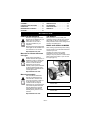
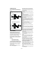
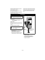
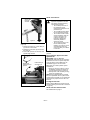
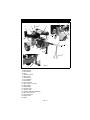
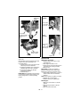
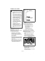
1
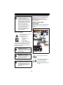
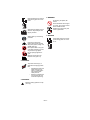
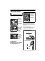
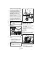
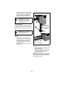
Log Splitter
Owner/Operator Manual
Manuel Du Propriétaire/Utilisateur
Manual del propietario/operador
Models
917001 – 27-Ton Log Splitter
917002 – 34-Ton Log Splitter
ENGLISH
FRANÇAIS
ESPAÑOL
03860300E 8/10
Printed in USA
TABLE OF CONTENTS
SAFETY. . . . . . . . . . . . . . . . . . . . . . . . . . 4
TROUBLESHOOTING . . . . . . . . . . . . . 20
ASSEMBLY . . . . . . . . . . . . . . . . . . . . . . . 8
SERVICE PARTS . . . . . . . . . . . . . . . . . 21
CONTROLS AND FEATURES . . . . . . . 10
ACCESSORIES. . . . . . . . . . . . . . . . . . . 21
OPERATION . . . . . . . . . . . . . . . . . . . . . 11
SPECIFICATIONS . . . . . . . . . . . . . . . . . 21
MAINTENANCE SCHEDULE . . . . . . . . 17
WARRANTY . . . . . . . . . . . . . . . . . . . . . 22
STORAGE . . . . . . . . . . . . . . . . . . . . . . . 19
INTRODUCTION
NON-ENGLISH MANUALS
THE MANUAL
Manuals in languages other than
English may be obtained from your
Dealer. Visit your dealer or
www.ariens.com for a list of
languages available for your
equipment.
Manuals printed in languages other
than English are also available as a
free download on our web site:
http://www.ariens.com
Manuales en idiomas diferentes
del ingles
Puede obtener manuales en
idiomas diferentes del inglés en su
distribuidor. Visite a su distribuidor
o vaya a www.ariens.com para
obtener una lista de idiomas
disponibles para su equipo.
También puede imprimir manuales
en idiomas diferentes del inglés
descargándolos gratuitamente de
nuestra página Web:
Before operation of unit, carefully and
completely read your manual. The contents
will provide you with an understanding of
safety instructions and controls during normal
operation and maintenance.
MODEL AND SERIAL NUMBERS
When ordering replacement parts or making
service inquiries, know the Model and Serial
numbers of your unit.
Numbers are located on the product
registration form in the unit literature
package. They are printed on a serial number
label, located on the frame of your unit near
the engine (figure 1).
http://www.ariens.com
Manuels non anglais
Des manuels dans différentes
langues sont disponibles chez
votre revendeur. Rendez-vous
chez votre revendeur ou allez sur
le site www.ariens.com pour
consulter la liste des langues
disponibles pour votre équipement.
Les manuels imprimés dans des
langues différentes de l’anglais
sont également disponibles en
téléchargement gratuit sur notre
site Web :
http://www.ariens.com
GB - 2
Unit Model &
Serial Number
Label
Figure 1
•
Record Unit Model and Serial
numbers here.
•
Record Engine Model and Serial
numbers here.
PRODUCT REGISTRATION
The Ariens dealer must register the product
at the time of purchase. Registering the
product will help the company process
warranty claims or contact you with the latest
service information. All claims meeting
requirements during the limited warranty
period will be honored, whether or not the
product registration card is returned. Keep a
proof of purchase if you do not register your
unit.
Customer Note: If the Dealer does not
register your product, please fill out, sign and
return the product registration card to Ariens
or go to www.ariens.com on the Internet
UNAUTHORIZED REPLACEMENT
PARTS
Use only Ariens replacement parts. The
replacement of any part on this unit with
anything other than an Ariens authorized
replacement part may adversely affect the
performance, durability, and safety of this unit
and may void the warranty. Ariens disclaims
liability for any claims or damages, whether
warranty, property damage, personal injury or
death arising out of the use of unauthorized
replacement parts.
NOTE: A complete Parts manual may be
downloaded from www.ariens.com on the
Internet
3. Review control functions and operation
of the unit. Do not operate the unit
unless all controls function as described
in this manual.
4. Review recommended lubrication,
maintenance and adjustments.
5. Review Limited Warranty Policy.
6. Fill out a product registration card and
return the card to the Ariens Company or
go to www.ariens.com.
DISCLAIMER
Ariens reserves the right to discontinue,
change, and improve its products at any time
without notice or obligation to the purchaser.
The descriptions and specifications contained
in this manual were in effect at printing.
Equipment described within this manual may
be optional. Some illustrations may not be
applicable to your unit.
DELIVERY
Customer Note: If you have purchased this
product without complete assembly and
instruction by your retailer, it is your
responsibility to:
• Read and understand all assembly
instructions in this manual. If you do
not understand or have difficulty
following the instructions, contact your
nearest Ariens Dealer for assistance.
NOTE: To locate your nearest Ariens Dealer,
go to www.ariens.com on the Internet.
WARNING: Improper assembly or
adjustments can cause serious
injury.
Before Attempting to Operate Your
Unit:
1. Make sure all assembly has been
properly completed.
2. Understand all Safety Precautions
provided in the manuals.
GB - 3
SAFETY
NOTATIONS
NOTE: General reference information for
proper operation and maintenance practices.
IMPORTANT: Specific procedures or
information required to prevent damage to
unit or attachment.
WARNING: This splitting machine
is capable of crushing or
amputating body parts. Failure to
observe the safety instructions in
the manuals and on decals could
result in serious injury or death.
Tragic accidents can occur if the
operator is not alert to the
presence of children. Never
assume that children will remain
where you last saw them.
Stop engine and allow moving
parts to stop before leaving
operator’s position.
SAFETY DECALS AND
LOCATIONS
ALWAYS replace missing or damaged Safety
Decals. Refer to figure 2 for Safety Decal
locations.
1
2
DANGER / PELIGRO
WARNING / ADVERTENCIA
ESCAPING HIGH PRESSURE HYDRAULIC FLUID HAZARD
ALWAYS keep body and hands away from pin holes or nozzles
which eject hydraulic fluid under pressure.
Escaping hydraulic fluid can puncture skin and cause blood
poisoning.
???
SAFETY ALERTS
Look for these symbols to point
out important safety
precautions. They mean:
• Attention!
• Personal Safety Is
Involved!
• Become Alert!
• Obey The Message!
READ THE OPERATOR’S MANUAL.
ONLY ONE PERSON SHOULD OPERATE
THE LOG SPLITTER AND LOAD THE LOGS.
SPLIT WOOD IN DIRECTION OF GRAIN ONLY.
STAY IN DESIGNATED OPERATOR ZONE.
HOLD LOG SIDES WHEN LOADING.
KEEP HANDS AWAY FROM RAM, WEDGE,
AND PARTLY SPLIT LOGS.
NEVER LEAVE THIS MACHINE UNATTENDED
DURING OPERATION.
STAY OFF SLOPES AND SLIPPERY SURFACES.
WEAR HEARING PROTECTION.
5
The safety alert symbol is used in decals and
with this manual. Understand the safety
message. It contains important information
about personal safety.
3
WARNING /
ADVERTENCIA
Maximum towing speed 45mph.
Loss of vehicle control and/or
machine damage can result.
DANGER: IMMINENTLY
HAZARDOUS SITUATION! If not
avoided, WILL RESULT in death
or serious injury.
4
Figure 2
0???
1. DANGER!
WARNING: POTENTIALLY
HAZARDOUS SITUATION! If not
avoided, COULD RESULT in
death or serious injury.
Read the operator’s manual.
OL1801
CAUTION: POTENTIALLY
HAZARDOUS SITUATION! If not
avoided, MAY RESULT in minor
or moderate injury. It may also be
used to alert against unsafe
practices.
OL1816
GB - 4
Keep children and others away
from unit while operating.
Only one person should
operate the log splitter and load
the logs.
4. WARNING!
Keep hands away from moving
parts. Moving parts can crush
or cut.
OL0480
Operate the log splitter on level
surfaces. Stay off slopes and
slippery surfaces.
No smoking, No sparks, No
flames.
Never fill fuel tank when engine
is running, hot or unit is indoors.
Never overfill fuel tank.
Replace fuel cap securely and
clean up spilled fuel.
OL0710
5. DANGER!
Always wear eye and hearing
protection.
Hold logs on sides when
loading. Keep hands and feet
away from cylinder, wedge, and
partially split logs.
Never place hands or any part
of the body between a log and
any part of the log splitter.
Do not split logs against the
grain.
Split logs end to end in the
direction of the grain only.
2. WARNING!
To prevent serious injury or
death from escaping hydraulic
fluid:
• ALWAYS keep body and
hands away from pin
holes or nozzles which
eject hydraulic fluid
under pressure.
• Escaping hydraulic fluid
can puncture skin and
cause blood poisoning.
3. WARNING!
Maximum towing speed of 45 mph
(72.4 kph)
GB - 5
Keep hands away from moving
parts. Moving parts can crush
or cut.
OPERATOR ZONE
This unit is designed to be operated by one
person located in the operator zone (see
figure 3).
Horizontal Operating Position
Operator
Zone
Operator
Zone
Vertical Operating Position
Operator
Zone
Figure 3
SAFETY RULES
If unit is to be used by someone other than
original purchaser; loaned, rented or sold,
ALWAYS provide this manual and any
needed safety training before operation.
Only the user can prevent and is responsible
for accidents or injuries occurring to
themselves, other people or property.
Read, understand, and follow all instructions
in the manual and on the machine before
starting.
Understand:
• How to operate all controls
• The functions of all controls
• How to STOP in an Emergency
ALWAYS remove spark plug wire from spark
plug before inspecting or working on this unit.
Inspect unit before each use for: missing or
damaged decals and shields. Replace or
repair as needed.
Before starting engine ensure that control
lever is in neutral position.
Keep children, people, and pets away. Be
alert and shut off unit if anyone enters work
area. Keep children under watchful care of a
responsible adult.
NEVER allow children to operate or play on
or near unit.
Keep operator zone clear of all split logs and
debris.
Operate unit only when there is sufficient light
to clearly see work area.
Only trained adults may operate unit. Training
includes being familiar with controls and
actual operation.
Many accidents occur when more than one
person operates the log splitter. If a helper is
assisting in loading logs to be split, never
operate the controls until the helper is clear of
the area.
NEVER operate unit after or during the use of
medication, drugs or alcohol.
NEVER allow anyone to operate this unit
when their alertness or coordination is
impaired.
Wear adequate safety shoes and protective
gloves.
DO NOT wear loose clothing or jewelry and
tie back hair that may get caught in moving
parts.
Protect eyes, face and head from objects that
may be thrown from unit. Wear appropriate
hearing protection. Always wear safety
goggles or safety glasses with side shields
when operating.
ALWAYS keep hands away from all moving
parts during operation. Moving parts can cut
or crush body parts.
ALWAYS keep hands away from all pinch
points.
Operate unit only when standing in operator
zone. Unit stabilizers must be extended
before starting unit.
DO NOT touch unit parts which might be hot
from operation. Allow parts to cool before
attempting to maintain, adjust or service.
ALWAYS stop unit and allow moving parts to
stop before leaving operator zone. Do not
leave running unit unattended.
DO NOT operate in the rain or in wet or damp
locations. Assure that operator zone is free or
debris and provides good footing.
Know the weight of logs. Limit logs to those
you can safely control and the unit can safely
handle.
Do not use log splitter for any purpose other
than splitting logs.
GB - 6
Do not move the unit up or down a hill by
hand. Use a tow vehicle with suitable braking
system.
Use extra care when towing unit. DO NOT
exceed 45 mph (72.4 kph).
Safety chains MUST be attached to vehicle
when towing unit.
NEVER allow anyone to ride on the unit.
NEVER transport cargo on the log splitter
Check local, state and federal laws before
towing. Any modifications required to meet
these laws are the responsibility of the
purchaser.
ALWAYS stop engine, lock beam in horizontal
position and close fuel shut-off valve when
transporting unit.
Keep unit free of leaves and other debris. DO
NOT spray water to clean unit.
ALWAYS keep protective structures, guards,
and panels in good repair, in place and
securely fastened. NEVER modify or remove
safety devices.
Stop and inspect equipment if there is an
unusual vibration. Repair, if necessary, before
restarting. Never make adjustments or repairs
without first disconnecting the spark plug
wire.
Keep all hardware properly tightened.
Maintain or replace safety and instruction
labels, as necessary.
Use only attachments or accessories
designed for your unit.
Check attachment components frequently. If
worn or damaged, replace with
manufacturer’s recommended parts.
This product is equipped with an internal
combustion engine. DO NOT use on or near
any unimproved, forest covered or brush
covered land unless the exhaust system is
equipped with a spark arrester meeting
applicable local, state or federal laws. A spark
arrester, if used, must be maintained in
effective working order by the operator.
DO NOT run engine in an enclosed area.
Always provide good ventilation. Fumes from
engine exhaust can cause injury or death.
Fuel is highly flammable and its vapors are
explosive. Handle with care. Use an
approved fuel container.
No smoking, No sparks, No flames. ALWAYS
allow engine to cool before servicing.
NEVER fill fuel tank when engine is running
or hot from operation.
NEVER fill or drain fuel tank indoors.
Replace fuel cap securely and clean up
spilled fuel.
Never fill fuel containers inside a vehicle or
on a truck or trailer bed with a plastic liner.
Always place containers on the ground away
from your vehicle before filling.
Keep the nozzle in contact with the rim of the
fuel tank or container opening at all times until
fueling is complete. Do not use a nozzle lockopen device.
If fuel is spilled on clothing, change clothing
immediately.
NEVER store fuel inside where there is an
open flame, such as a water heater.
HYDRAULIC FLUID can result in severe
burns. Fluid in hydraulic system can
penetrate skin and result in serious injury or
death.
• Be sure to stop the engine and relieve
hydraulic pressure before doing any
work on hydraulic parts.
• Keep body and hands away from pin
holes or nozzles which expel hydraulic
fluid when under pressure. Use paper
or cardboard, not hands, to search for
leaks.
• Ensure all hydraulic fluid connections
are tight and all hydraulic hoses and
lines are in good condition before
applying pressure to system.
• FOREIGN FLUID INJECTED INTO
BODY can result in gangrene. Fluid
must be surgically removed within a
few hours by a doctor familiar with this
form of injury.
• Do not adjust the pressure settings on
the hydraulic pump or valve.
ALWAYS maintain unit in safe operating
condition. Damaged or worn out muffler can
cause fire or explosion.
Disconnect unit from tow vehicle before
using.
Use wheel chocks to prevent movement of
unit during operation.
Logs should be cut with square ends before
placing on splitter.
When placing logs on unit position hands on
sides (bark side) of logs and not on the ends.
Never place hands or any part of the body
between a log and any part of the log splitter.
Do not attempt to stabilize logs with legs or
feet while operating. Moving parts can cut off
or crush body parts.
Do not split more than one log at a time
unless the cylinder has been fully extended
and a second log is needed to complete the
separation of the first log.
GB - 7
Position logs against end plate grips before
operating hydraulic cylinder.
Split logs end to end in the direction of the
grain, not against the grain.
Keep fingers and hands away from cracks in
logs while splitting. These can quickly close
and pinch or crush body parts.
On logs that are not square place the longest
portion of the log closest to the beam and the
most square end against the splitter wedge.
Use only your hand to operate the control
lever.
ASSEMBLY
Tongue
Assembly
WARNING: AVOID INJURY.
Read and understand the entire
Safety section before proceeding.
Tools Required:
• Two 3/4" wrenches or sockets.
• Thin-nosed pliers.
Unpack Unit
Remove unit and all other components from
the shipping container and move onto a level
surface.
Assemble Tongue Assembly
CAUTION: DO NOT start engine
until all assembly steps have
been completed.
Safety
Chain
1. Ensure that jack stand is down and in
locked position.
2. Remove rear hex bolt and nut from
frame and retain (see figure 4).
3. Remove front hex bolt and nut retaining
tongue assembly to frame and retain.
Remove and
retain hex bolts
and nuts.
Jack
Stand
Figure 4
4. Position tongue assembly in operating
position on frame.
5. Insert hex bolts through tongue
assembly and frame (see figure 5).
6. Secure hex bolts with hex nuts.
7. Tighten all hardware.
GB - 8
Check Tire Pressure
Secure with
hex bolts
and nuts.
CAUTION: Avoid injury!
Explosive separation of tire and
rim parts is possible when they
are serviced incorrectly:
• Do not attempt to mount a
tire without the proper
equipment and experience to
perform the job.
• Do not inflate the tires above
the recommended pressure.
• Do not weld or heat a wheel
and tire assembly. Heat can
cause an increase in air
pressure resulting in an
explosion. Welding can
structurally weaken or
deform the wheel.
• Do not stand in front or over
the tire assembly when
inflating. Use a clip-on chuck
and extension hose long
enough to allow you to stand
to one side.
Figure 5
Attach Control Lever
(Figure 6)
1. Remove the clevis pin (1) and cotter pin
(2) from the control valve.
2. Rotate the control lever up and reinsert
the clevis pin.
3. Insert cotter pin back into clevis pin and
spread tangs outward.
See SPECIFICATIONS on page 21 for tire
pressure.
Purge Hydraulic System and Add
Hydraulic Oil
2
1
Rotate lever
forward and into
position.
Install clevis pin
and cotter pin.
IMPORTANT: ADD OIL BEFORE
OPERATING! Add hydraulic oil to operating
level before first use. The system may take
up to two gallons. See HYDRAULIC OIL
SYSTEM on page 18. Do not overfill.
Before first use or after hydraulic system
maintenance:
1. Purge any air in the system by cycling
the hydraulic cylinder (see Purge Air
From Hydraulic System on page 19).
2. Add hydraulic oil as necessary to bring
system to operating level.
NOTE: Some hydraulic fluid may overflow
from the cap/breather as the system warms
up and the fluid expands. Do not operate the
unit without the proper amount of oil in the
reservoir.
Fill Engine Fuel Tank
Figure 6
Refer to Engine Manual for proper fuel type
and tank capacity (see Add Fuel to Fuel Tank
on page 14).
Check Function of All Controls
See OPERATION on page 11.
GB - 9
CONTROLS AND FEATURES
17
1
2
3
16
5
6
14
13
8
19
4
15
11
20
7
9
10
12
18
Figure 7
1. Control Lever
2. Splitter Wedge
3. End Plate/Grip
4. Beam
5. Hydraulic Cylinder
6. Stripper Plate
7. Oil Drain Plug
8. Fuel Tank/Filler
9. Recoil Starter
10. Front Jack Stand
11. Hitch Coupler – 2-In. Ball
12. Safety Chains
13. Rear Stabilizer
14. Hydraulic Pump
15. Hydraulic Tank
16. Hydraulic Tank Dipstick/Breather
17. Beam Assembly Lock
18. Hydraulic Oil Filter
19. Engine Switch
20. Muffler
GB - 10
OPERATION
CONTROLS AND FEATURES
The fuel shut-off valve has two positions:
Closed Position:
Use this position
to service,
transport, or
store the unit.
WARNING: AVOID INJURY.
Read and understand the entire
Safety section before proceeding.
See figure 7 for all controls and features
locations.
Open Position:
Use this position
to run the unit.
Engine Switch
1
2
The engine
switch has two
positions:
1. OFF – Engine
will not start or
run.
2. ON – Engine
will start and run.
Figure 8
Recoil Starter Handle
When pulled, handle will turn engine over.
IMPORTANT: DO NOT let handle snap back
against starter.
Choke Control Lever
1.Choke Closed
position: chokes
off air to engine
for easier start.
2.Choke Open
position: allows
1
2
for normal
operation.
IMPORTANT: Gradually open choke after
engine starts.
Control Lever (Figure 9)
The control lever is used to move the splitting
wedge in or out when operating in the
horizontal position or up and down when
operating in the vertical position.
Horizontal Operating Position
1
2
Throttle Control Lever
The throttle
controls the
engine speed. To
increase or
decrease the
engine speed,
adjust to:
1. Fast (normal or warm starts)
2. Part-Throttle
3. Slow (cold weather starts)
1
2
3
Vertical Operating Position
Fuel Shut-Off Valve
IMPORTANT: The fuel shut-off valve MUST
be in the closed position prior to
transporting the unit.
3
2
1
Figure 9
GB - 11
3
Out/Down (1) – Move lever in this direction to
extend cylinder toward end plate. Keep
pressure on lever until log is split. Lever does
not lock in this position. Release as soon as
log is split or cylinder is fully extended.
NOTE: Splitter wedge is designed to reach
full extension and stop between 1 and 2" (25
and 50 mm) before contacting end plate.
IMPORTANT: When cylinder is fully
extended do not hold lever in out position.
Pump damage will result.
Neutral (2) – In this position the cylinder does
not move even though the engine is running.
Return/Up (3) – Move lever in this direction to
retract cylinder. Push lever fully in this
direction to lock in return mode. Lever will
automatically return to neutral once cylinder
fully retracts.
Figure 11
WARNING: Keep hands and
fingers away from splitter wedge
and stripper plates during cylinder
retraction.
IMPORTANT: Rear stabilizer must be in the
transport position before placing beam in
vertical operating position (see Rear
Stabilizer on page 14).
To move beam to horizontal position:
1. Carefully rotate beam down until seated
on lock bracket.
2. Turn beam lock until pin lines up with
hole in lock bracket and release
(Figure 10).
3. Ensure that beam lock pin fully engages
in bracket.
Beam Lock
Beam
Lock
Stripper Plates
(Figure 12)
The stripper plates are designed to remove a
log that has partially split but remains stuck
on the wedge.
Stripper Plates
Figure 10
Locks the beam in the horizontal operating
position. To move beam to vertical operating
position:
1. Pull beam lock out until the pin clears
the mount (Figure 10).
2. Rotate beam lock slightly so pin does
not return to hole in mount.
3. Lift beam until it rotates to vertical
position (Figure 11).
CAUTION: Beam assembly is
heavy. Use care when moving
between vertical and horizontal
positions.
Figure 12
To remove stuck logs from the splitter wedge:
1. Move the control lever to the Return/Up
position.
2. Allow the cylinder to retract until the
stuck log contacts the stripper plates.
GB - 12
3. Continue to retract the cylinder until the
log is dislodged from the splitter wedge.
4. Once removed from the splitter wedge
rotate log and split from a different
location or split log from the other end.
CAUTION: Do not use the unit if
the stripper plates are bent or
damaged. Bent or damaged
stripper plates must be repaired
or replaced before use.
917001
Notch
Front Jack Stand
Remove hair
pin and clevis
pin and rotate
jack stand up
or down.
Front jack stand must be locked in the down
position whenever the unit is in use and in the
transport position when moving or towing the
unit.
CAUTION: Jack stand must be
locked in the transport position
before towing the unit.
Handle
917001
(Figure 13)
1. Remove hair pin from clevis pin and
remove clevis pin from tongue bracket.
2. Rotate jack stand up or down until the
top edge of the handle on the stand
aligns with the upper or lower notch in
the tongue bracket.
3. Insert clevis pin into tongue bracket and
insert hair pin.
Reinstall clevis
pin and hair pin.
Figure 13
917002
(Figure 14)
1. Pull out and hold the lock handle to allow
jack stand to rotate.
2. Rotate the jack stand up or down until
the lock handle aligns with the upper or
lower holes in the jack assembly.
3. Release lock handle.
NOTE: When locked in the down position the
tongue height can be adjusted by rotating the
height adjustment handle clockwise (up) or
counterclockwise (down).
GB - 13
917002
HeightAdjustment
Handle
Transport
Position
Remove hair
pin and slide
lock pin out.
Pull out lock
handle and rotate
jack stand up or
down.
Work
Position
Insert lock pin
through
brackets and
insert hair pin.
Release handle
to lock in place.
Figure 14
Figure 15
Rear Stabilizer
OPERATION
(Figure 15)
Rear stabilizer must be positioned down and
locked in place when operating in the
horizontal position.
1. Remove hair pin from upper lock pin and
slide lock pin out from brackets.
2. Rotate rear stabilizer down until holes in
stabilizer align with holes in brackets.
3. Insert lock pin all the way through
brackets and stabilizer.
4. Reinstall hair pin.
IMPORTANT: Rear stabilizer must be locked
in the transport position before towing unit or
before placing beam in vertical operating
position.
Add Fuel to Fuel Tank
1. ALWAYS place unit in open or wellventilated area.
2. Stop engine and allow to cool.
3. Clean fuel cap and surrounding area to
prevent dirt from entering fuel tank.
4. Remove cap.
IMPORTANT: DO NOT use gasohol or
gasoline containing alcohol. See Engine
Manual for correct type and grade of fuel.
5. Fill fuel tank to within 1/2 in. (1.2 cm) of
bottom of filler neck with unleaded
gasoline.
NOTE: Tank capacity is .9 gallon (3.4 liters).
6. Replace fuel cap and tighten.
7. ALWAYS clean up any spilled fuel.
Start Engine
1. Make sure control lever is in neutral
position.
2. Move the engine switch to the ON
position.
3. Open the fuel shut off valve.
GB - 14
4. Set the choke lever based on engine
temperature (see Choke Control Lever
on page 11).
5. Slowly pull the recoil starter until engine
compression makes pulling difficult. Let
the starter rewind a little, and then pull
smoothly and quickly to start the engine.
6. Repeat step 5 as needed.
7. Fully open the choke and set the throttle
to full fast before operating the unit.
CAUTION: Avoid damage or
injury! Use maximum caution
when towing log splitter:
• DO NOT exceed 45 mph
(72.4 kph).
• Obey all applicable local,
state and federal laws
regarding towing.
• DO NOT carry passengers,
cargo or logs on the towed
unit.
• Allow for the extra length of
the unit when turning,
parking, crossing
intersections and in all driving
situations.
• Ensure that stabilizers are
locked in the transport
position and that the beam is
locked before moving unit.
• Drive slowly and take extra
caution over rough terrain.
Stop Engine
1. Return cylinder to fully retracted
position.
2. Move throttle lever to slow position.
3. Move the engine switch to the OFF.
4. Close the fuel shut-off valve.
TRANSPORTING UNIT
IMPORTANT: Check local, state and federal
laws before towing unit. Any modifications
required to meet these laws are the
responsibility of the purchaser.
OPERATION
CAUTION: Unit can cause
serious injury if it rolls out of
control or tips over. Chock wheels
when unit is not attached to a tow
vehicle.
Work Site
Ensure that wheel bearings are well packed
with grease and that tires are inflated properly
before towing. To tow unit:
1. Place beam in horizontal position and
engage beam lock (see Beam Lock on
page 12).
2. Move fuel shut-off valve to closed
position.
3. Move rear stabilizer to transport position
and lock in place (see Rear Stabilizer on
page 14).
4. Attach log splitter hitch to tow vehicle
with class 1 or higher receiver and 2-in.
ball. Adjust hitch coupler to ensure lock
lever fully locks onto ball with no excess
movement. Install a locking pin or lock
through the lock lever.
5. Move front jack stand to transport
position and lock in place (see Front
Jack Stand on page 13)
NOTE: Tow vehicles with low ball heights will
require the jack stand to be stored before
attaching the hitch coupler to the ball.
6. Cross unit safety chains under the
coupler and attach to tow vehicle.
Set up log splitter in an area that provides:
• a dry level surface.
• good footing that is free of debris or
other tripping hazards.
• sufficient clearance for engine exhaust
to not blow directly on combustible
material.
Disconnect the log splitter from the tow
vehicle before operating. If splitting logs in the
horizontal position, move rear stabilizer to
work position (see Rear Stabilizer on
page 14). Chock the wheels to prevent
movement during operation.
Warm Up Unit
When using the unit in temperatures of 68°
F (20° C) or lower, the hydraulic system
should be cycled before splitting logs. This
allows the cool hydraulic oil in the cylinder to
be circulated before placing a load on the
hydraulic system.
1. Start the engine and allow it warm up
(see Start Engine on page 14).
2. Cycle the cylinder through three or four
full extension/retraction cycles.
3. Proceed with splitting logs.
IMPORTANT: Always split logs with engine
set at Fast position.
GB - 15
FOR BEST PERFORMANCE
Splitting Logs
•
WARNING: AVOID INJURY.
Read and understand the entire
Safety section before proceeding.
•
•
Determine if the size of the logs to be split
can be safely and comfortably lifted up onto
the beam in the horizontal position. If logs are
too heavy for the operator, position the beam
in the vertical position for splitting.
CAUTION: During operation,
engine and hydraulic system are
hot. Always stop engine and allow
unit to cool before changing beam
positions.
Working only in the Operator Zone (see
OPERATOR ZONE on page 6):
1. Fully retract cylinder.
2. Place log on beam:
• Split only from log ends, with the grain.
• Position log against grips on end plate
with the squarest end toward the
splitter edge.
• Position hands on sides of logs when
placing logs on unit and not on the
end. Never place hands or any part of
the body between a log and any part
of the log splitter.
• Do not attempt to stabilize logs with
legs or feet while operating.
3. Using only your hand, push the control
lever toward the log.
4. Hold the lever in the out position until log
is split.
5. Allow split logs to drop to the ground.
DO NOT try to catch split logs.
6. Move control lever away from the log
until it locks into retract position. Lever
will automatically return to neutral once
cylinder is fully retracted.
7. Do not load another log or remove split
pieces until the cylinder has completely
stopped and the control lever is in the
neutral position. Do not reach across the
unit.
8. Split only one log at a time unless the
cylinder has been fully extended and a
second log is needed to complete the
separation of the first log.
9. Move split logs as necessary to ensure
that all tripping hazards have been
eliminated from the operator zone.
GB - 16
•
•
Ensure that logs to be split are cut as
square as possible.
Split dry, cured logs. Wet or recently
cut logs will be more difficult to split.
Split logs with straight grain. Logs with
knots or twisted or irregular grain
patterns will be more difficult to split.
Move split logs as needed to keep
operator zone free of tripping hazards.
When splitting logs that are not square
place the longest portion of the log
closest to the beam and the most
square end against the splitter wedge.
MAINTENANCE SCHEDULE
WARNING: AVOID INJURY. Read
and understand the entire Safety
section before proceeding.
IMPORTANT: Proper maintenance can
prolong the life of unit. The following chart
shows the recommended service schedule.
Interval
Task
Action
Each Use
Clean Unit
Clean engine and hydraulic tank of all dirt and debris. DO NOT
spray unit with water. Do not use solvents, hard cleaners, or
abrasives.
NOTE: Protect painted surfaces with automotive-type wax.
Check Tires
See SPECIFICATIONS on page 21 for correct tire pressure. See
Check Tire Pressure on page 9.
Check Engine Refer to engine manual.
Oil
Check
See Checking Hydraulic Oil Level on page 18.
Hydraulic Oil
Level
Check
Hydraulic
Lines
Check for leaking, kinked or damaged lines. Replace as necessary.
See HYDRAULIC OIL SYSTEM on page 18.
Follow Engine Perform scheduled engine maintenance. Refer to Engine Manual
Maintenance for detailed instructions.
Schedule
50 Hours
or Every
Season
Check
Fasteners
Check all fasteners. Replace fasteners that are missing or
damaged. Tighten all nuts and bolts to the correct torque value.
100 Hours Change
Drain oil from hydraulic tank, replace filter and refill tank with
or Every
Hydraulic Oil hydraulic oil. See Recommended Hydraulic Oil on page 18.
Season
and Filter
Check
Hydraulic
Drive
Coupling
Inspect hydraulic drive coupling for damage or deterioration.
Replace as necessary.
Drive
Coupling
Hydraulic
Pump
Engine
Check Wheel Remove bearing dust caps and inspect and repack wheel bearings
Bearings
with grease. After packing bearings seat bearings by tightening the
spindle nut snug. Loosen nut, spin wheel and retighten slightly until
first slot in castle nut aligns with hole in hub. Replace cotter pin and
dust cap. Wheel should spin freely with no wobble.
GB - 17
HYDRAULIC OIL SYSTEM
Hydraulic Oil
Reservoir
Cap/Breather
WARNING: HYDRAULIC FLUID
can result in severe burns. Fluid in
hydraulic system can penetrate
skin and result in serious injury or
death.
Be sure to stop the engine and
relieve hydraulic pressure before
doing any work on hydraulic parts.
Keep body and hands away from
pin holes or nozzles which expel
hydraulic fluid when under
pressure. Use paper or cardboard,
not hands, to search for leaks.
Ensure all hydraulic fluid
connections are tight and all
hydraulic hoses and lines are in
good condition before applying
pressure to system.
FOREIGN FLUID INJECTED
INTO BODY can result in
gangrene. Fluid must be surgically
removed within a few hours by a
doctor familiar with this form of
injury.
Hydraulic Oil Level
Operating Range
Figure 16
9. Add hydraulic oil as necessary. Do not
overfill.
Recommended Hydraulic Oil
Only use the following hydraulic oils:
• ISO32 hydraulic oil (Ariens part
number 00069100)
Checking Hydraulic Oil Level
•
Dexron® III/Mercon® automatic
transmission fluid
10 weight AW hydraulic oil
IMPORTANT: ADD OIL BEFORE
OPERATING! Add hydraulic oil to operating
level before use. Do not overfill.
To check the hydraulic oil level:
1. Park the unit on a level surface.
2. Start the unit and run it to operating
temperature (about 10 minutes).
3. Cycle the hydraulic cylinder in and out
two or three times.
4. Shut off engine.
5. Remove any dirt that may be around the
cap/breather on the hydraulic reservoir.
6. Remove cap/breather and wipe oil level
dipstick clean.
7. Replace cap/breather and fully tighten.
8. Remove cap/breather and check oil
level on dipstick. Oil should be within the
operating range. See figure 16.
•
Pro-Mix™ AW-32 Hydraulic Oil
•
Changing Hydraulic Oil and Filter
NOTE: Change the hydraulic oil and oil filter
every season or 100 hours.
1. Clean area around hydraulic supply
hose.
2. Place container under oil filter and
hydraulic supply hose to catch oil.
3. Remove hose clamp and disconnect
hose from hydraulic tank. See figure 17.
Hydraulic Tank
Hydraulic
Supply
Hose
Figure 17
4. Remove oil filter.
5. Allow tank to drain.
6. Reinstall hydraulic suction hose and
tighten hose clamp.
7. Lubricate rubber gasket on new oil filter
with clean hydraulic oil.
GB - 18
8. Spin new oil filter onto filter housing until
it makes contact. Tighten oil filter
another 1/2 turn.
9. Add new oil to the oil tank.
10. Check hydraulic oil level.
11. Properly dispose of waste oil.
Purge Air From Hydraulic System
1. With the engine running, extend the
hydraulic cylinder out fully and then
retract fully.
2. Repeat 4 – 5 times. Erratic movement in
the hydraulic cylinder indicates that
there is air in the system.
3. Stop the engine and check the hydraulic
oil level. Add if necessary.
4. Repeat extending and retracting of
hydraulic cylinder unit motion is
consistent and smooth in both
directions.
5. Ensure that hydraulic oil is at proper
level.
IMPORTANT: At this point a large amount of
hydraulic oil has been drawn into the
hydraulic cylinder and hoses. Be sure to refill
the oil reservoir to prevent pump damage.
STORAGE
To Take the Unit Out of Storage
SHORT TERM
NEVER spray unit with high pressure water
or store unit outdoors.
Inspect unit for visible signs of wear,
breakage or damage.
Keep all nuts, bolts and screws properly
tightened and know unit is in safe working
condition.
Store unit in a cool, dry protected area.
Protect bare-metal areas with a light coat of
oil or anti-rust compound.
LONG TERM
Perform all steps found in Short Term
storage.
Touch up all scratched painted surfaces.
Remove weight from wheels by putting
blocks under frame or axle.
Fuel System
Gasoline left in the fuel system for extended
periods without a stabilizer will deteriorate,
resulting in gum deposits in the system.
These deposits can damage the carburetor
and the fuel hoses, filter and tank. Prevent
deposits from forming in the fuel system
during storage by adding a quality fuel
stabilizer to the fuel. Follow the
recommended mix ratio found on the fuel
stabilizer container.
To treat the fuel system for storage:
1. Add fuel stabilizer (Ariens part number
00592900) according to manufacturer’s
instructions.
2. Run engine for at least 10 minutes after
adding stabilizer to allow it to reach the
carburetor.
NEVER store the engine with fuel in the fuel
tank inside of a building with potential
sources of ignition.
GB - 19
1. Refer to the engine service manual to
prepare the engine for service.
2. Put fresh, clean fuel in the fuel tank.
3. Begin the maintenance schedule.
TROUBLESHOOTING
PROBLEM
Engine will not
start.
PROBABLE CAUSE
CORRECTION
1. Engine switch in
Off position.
1. Move switch to On position (see Engine
Switch on page 11).
2. Fuel shut-off valve
in Off position.
2. Move valve to On position (see Fuel ShutOff Valve on page 11).
3. Fuel tank empty.
3. Fill fuel tank with fuel (see Fill Engine Fuel
Tank on page 9).
4. Spark plug
disconnected.
4. Connect spark plug.
5. Faulty spark plug.
5. Replace spark plug.
6. Choke lever in
wrong position.
6. Adjust choke lever position (see Choke
Control Lever on page 11).
7. Faulty engine.
7. See your Ariens Dealer.
Engine
overheats.
1. Debris
accumulated on
engine and
cooling fins.
1. Clean debris from engine and cooling fins.
Cylinder does
not extend or
retract when
control lever is
moved.
1. Low hydraulic oil
level.
1. Refill hydraulic oil to proper level (see
Checking Hydraulic Oil Level on page 18).
2. Kinked or pinched
hydraulic lines.
2. Repair or replace damaged hydraulic lines.
3. Hydraulic drive
coupling broken.
3. Replace hydraulic drive coupling (see
MAINTENANCE SCHEDULE on page 17).
4. Faulty hydraulic
pump.
4. See your Ariens Dealer.
5. Faulty control
valve.
5. See your Ariens Dealer.
Excessive
vibration or noise
from hydraulic
drive coupling.
1. Worn or damaged
drive coupling.
1. Replace hydraulic drive coupling (see
MAINTENANCE SCHEDULE on page 17)
Erratic
movement of
cylinder.
1. Air in hydraulic
system.
1. Purge air from hydraulic system (see Purge
Air From Hydraulic System on page 19).
Control lever
sticks.
1. Debris in control
lever linkage.
1. Clean and lubricate linkage.
2. Dented rear cap
on control lever
valve assembly.
2. See your Ariens Dealer.
GB - 20
SERVICE PARTS
ACCESSORIES
See your authorized Ariens dealer for
genuine OEM service parts.
See your authorized Ariens dealer to add
these optional accessories to your unit.
Part No.
Description
Part No.
Qty
Description
03835951
1
Wedge, Splitter
71701200
Work Table Kit
03931900
1
Hydraulic Oil Filter
71701300
Light Kit
20020002
1
Air Filter
71701400
License Plate Light Holder
20020001
1
Spark Plug
71701500
Engine Cover Kit
00069100
AR
Hydraulic Oil – ISO 32
71701600
Log Cradle Kit
71701800
Log Splitter Handle Kit
00592900
Fuel Stabilizer 4 oz.
SPECIFICATIONS
Model Number
Model
917001
917002
27-Ton Log Splitter
34-Ton Log Splitter
Engine
Engine
Subaru
Engine Model Number
Displacement – Cu. In. (cc)
SP170 – CARB
EX21 – CARB
10.31 (169)
12.87 (211)
Max RPM
3750±150
Oil Capacity – Pt. (L)
1.3 (.6)
Fuel Tank Capacity Qt. (L)
3.6 (3.4)
Fuel Octane Rating
Refer to Engine Manual
Hydraulic System Capacity – Gal. (L)
4.5 (17)
Splitting Force – Ton (kg)
27 (24,494)
Cylinder Cycle Time – Seconds
34 (30,844)
17
18
Bed Capacity: Log Length – in. (cm)
25 (63.5)
Size and Weight
Length: Horizontal Position – in. (cm)
86.25 (219)
Length: Vertical Position – in. (cm)
83.75 (212.7)
Width – in. (cm)
38.25 (97.2)
Height: Horizontal Position – in. (cm)
46.50 (118.1)
Height: Vertical Position – in. (cm)
64.75 (164.5)
Weight – lbs. (kg)
500 (226.8)
525 (238.2)
Tires
Tire Size – in.
4.80/4.00 x 8
Tire Pressure – psi (kPa)
30 (137.9)
Maximum Towing Speed – mph (kph)
45 (72.4)
Hitch Coupler – in. (cm)
2 (5.1)
GB - 21
Two-Year Limited Lawn
and Garden Warranty
This warranty statement applies only to 21-Inch Walk Behind Lawn Mowers, Wide Area
Walks, AMP Wide Area Walks, Tillers, String Trimmers, Log Splitters, Edgers and Power
Brushes
Ariens Company (Ariens) warrants to the original purchaser that Ariens and Gravely brand consumer
products manufactured and sold by Ariens will be free from defects in material and workmanship for a period
of two years after the date of purchase. An authorized Ariens dealer (Ariens brand products) or Gravely
dealer (Gravely brand products) will repair any defect in material or workmanship, and repair or replace any
defective part, subject to the conditions, limitations and exclusions set forth herein. Such repair or
replacement will be free of charge (labor and parts) to the original purchaser except as noted below.
Two-Year Limited Warranty on AMP™ Series Battery Packs and Subassemblies
The battery pack and/or battery subassemblies on AMP series electric mowers is/are warranted to the
original purchaser for two years from the date of purchase. Ariens will replace, free of charge to the
original purchaser, any battery pack and/or battery subassembly that fails due to defect in material or
workmanship for one year after the date of purchase. For the next 12 months, Ariens will cover the prorated cost of replacing a battery pack and/or battery subassembly that fails due to defect in material or
workmanship. This warranty does not apply to battery packs or battery subassemblies that fail due to
accident, neglect, abuse, improper maintenance, improper storage or improper charging procedures.
One-Year Limited Warranty on Professional/Commercial 21-inch Walk-Behind Lawn
Mowers
21-inch walk-behind lawn mowers labeled or designated by Ariens as a Professional/Commercial product put to any business use, agricultural, commercial, or industrial, are warranted to the original purchaser to be free from defects in material and workmanship for a period of one year after the date of
purchase.
90-Day Limited Warranty on Service Parts and Accessories
Genuine Ariens or Gravely brand service parts and accessories are warranted to be free from defects
in material and workmanship for a period of 90 days after the date of purchase. An authorized Ariens or
Gravely dealer will repair or replace any such part or accessory free of charge, except for labor, during
that period.
Except for 21-inch walk-behind lawn mowers labeled or designated by Ariens as a Professional/Commercial
product, the duration of all warranties herein applies only if the product is put to personal use around a
household or residence. If the product is put to any business use, agricultural, commercial, or industrial, then
the duration of these warranties shall be 90 days after the date of purchase. If any product is rented or
leased, then the duration of these warranties shall be 90 days after the date of purchase.
Exceptions, Limitations, Exclusions
Customer Responsibilities
Register the product immediately at the time of sale. If the dealer does not register the product, the
customer must complete the product registration card in the literature package and return it to the Ariens
Company, or register the unit online at www.ariens.com or www.gravely.com.
To obtain warranty service, the original purchaser must:
• Perform the maintenance and minor adjustments explained in the owner’s manual.
• Promptly notify Ariens or an authorized Ariens or Gravely service representative of the need for
warranty service.
• Transport the product to and from the place of warranty service.
• Have the warranty service performed by an authorized Ariens or Gravely service representative.
ARIENS COMPANY
GRAVELY® | STENS® | LOCKE® | NATIONAL® | BYNORM® | EVERRIDE® | GREAT DANE®
Con_L&G_2010
22
To find an Ariens or Gravely authorized service representative, contact Ariens at:
655 W. Ryan Street
Brillion, WI 54110
(920) 756 - 2141
www.ariens.com
www.gravely.com
Exceptions and Limitations
•
Batteries are warranted only for a period of 12 months after date of purchase, on a prorated basis. For
the first 90 days of the warranty period, a defective battery will be replaced free of charge. If the
applicable warranty period is more than 90 days, Ariens will cover the prorated cost of any defective
battery, for up to 12 months after the date of purchase. This battery limited warranty does not apply to
the battery packs on AMP series products.
•
Engines and engine accessories are covered only by the engine manufacturer’s warranty and are not
covered by this warranty.
Parts that are not genuine Ariens or Gravely service parts are not covered by this warranty.
The following maintenance, service and replacement items are not covered by this warranty unless
they are noted in the Limitations section above: lubricants, spark plugs, oil, oil filters, air filters, fuel
filters, brake linings, brake arms, brake shoes, runners, scraper blades, shear bolts, mower blades,
mower vanes, tines, brushes, headlights, light bulbs, knives, cutters.
Any misuse, alteration, improper assembly, improper adjustment, neglect, or accident which requires
repair is not covered by this warranty.
This warranty applies only to products purchased in the United States (including Puerto Rico) and
Canada. In all other countries, contact place of purchase for warranty information.
Exclusions – Items Not Covered by This Warranty
•
•
•
•
Disclaimer
Ariens may from time to time change the design of its products. Nothing contained in this warranty shall be
construed as obligating Ariens to incorporate such design changes into previously manufactured products,
nor shall such changes be construed as an admission that previous designs were defective.
LIMITATION OF REMEDY AND DAMAGES
Ariens Company’s liability under this warranty, and under any implied warranty that may exist, is limited to
repair of any defect in workmanship, and repair or replacement of any defective part. Ariens shall not be
liable for incidental, special, or consequential damages (including lost profits). Some states do not allow the
exclusion of incidental or consequential damages, so the above limitation or exclusion may not apply to you.
DISCLAIMER OF FURTHER WARRANTY
Ariens Company makes no warranty, express or implied, other than what is expressly made in this
warranty. If the law of your state provides that an implied warranty of merchantability, or an implied
warranty of fitness for particular purpose, or any other implied warranty, applies to Ariens Company,
then any such implied warranty is limited to the duration of this warranty. Some states do not allow
limitations on how long an implied warranty lasts, so the above limitation may not apply to you.
This warranty gives you specific legal rights, and you may also have other rights which
vary from state to state.
ARIENS COMPANY
GRAVELY® | STENS® | LOCKE® | NATIONAL® | BYNORM® | EVERRIDE® | GREAT DANE®
Con_L&G_2010
23
Ariens Company
655 West Ryan Street
Brillion, WI 54110-1072
920-756-2141
Fax 920-756-2407
www.ariens.com