1
D
Schnellstartanleitung
HomeMatic Zentrale CCU1
HM-Cen-3-1
GB
Seite 3 - 14
Quick-start instructions
HomeMatic Central CCU1
HM-Cen-3-1
Page 16 - 27
1. Ausgabe Deutsch 02/2008
Dokumentation © 2008 eQ-3 Ltd., Hong Kong
Alle Rechte vorbehalten. Ohne schriftliche Zustimmung des Herausgebers darf
dieses Handbuch auch nicht auszugsweise in irgendeiner Form reproduziert werden
oder unter Verwendung elektronischer, mechanischer oder chemischer Verfahren
vervielfältigt oder verarbeitet werden.
Es ist möglich, dass das vorliegende Handbuch noch drucktechnische Mängel oder
Druckfehler aufweist. Die Angaben in diesem Handbuch werden jedoch regelmäßig
überprüft und Korrekturen in der nächsten Ausgabe vorgenommen. Für Fehler technischer oder drucktechnischer Art und ihre Folgen übernehmen wir keine Haftung.
Alle Warenzeichen und Schutzrechte werden anerkannt.
Printed in Hong Kong
Änderungen im Sinne des technischen Fortschritts können ohne Vorankündigung
vorgenommen werden.
66288 / V 1.2
1. English edition 02/2008
Documentation © 2008 eQ-3 Ltd., Hong Kong
All rights reserved. No parts of this manual may be reproduced or processed in any
form using electronic, mechanical or chemical processes in part or in full without the
prior explicit written permission of the publisher.
It is quite possible that this manual has printing errors or defects. The details
provided in this manual are checked regularly and corrections are done in the next
edition. We do not assume any liability for technical or printing errors.
All registered trade marks and copyrights are acknowledged.
Printed in Hong Kong
We reserve the right to make changes due to technical advancements without prior
notice.
66288 / V 1.2
2
Inhaltsverzeichnis
1
Hinweise zu dieser Anleitung . . . . . . . . . . . . . . . . . . . . . . . . . . . . . . . . . . . . . . . 4
2
Allgemeine Systeminformation zu HomeMatic . . . . . . . . . . . . . . . . . . . . . . . . . 4
3
Allgemeine Hinweise zum Funkbetrieb . . . . . . . . . . . . . . . . . . . . . . . . . . . . . . . 4
4
Kurzer Überblick . . . . . . . . . . . . . . . . . . . . . . . . . . . . . . . . . . . . . . . . . . . . . . . . . 5
4.1
Lieferumfang . . . . . . . . . . . . . . . . . . . . . . . . . . . . . . . . . . . . . . . . . . . . . . . . . . . . 5
4.2
Bedienelemente und Anschlüsse . . . . . . . . . . . . . . . . . . . . . . . . . . . . . . . . . . . . 5
4.3
Anschluss des Netzteils und Einlegen der Batterien . . . . . . . . . . . . . . . . . . . . 6
4.4
Anforderungen an den verwendeten Computer zur Bedienung der Zentrale . 6
5
Montage . . . . . . . . . . . . . . . . . . . . . . . . . . . . . . . . . . . . . . . . . . . . . . . . . . . . . . . 7
5.1
Als Standgerät . . . . . . . . . . . . . . . . . . . . . . . . . . . . . . . . . . . . . . . . . . . . . . . . . . . 7
5.2
Wandmontage . . . . . . . . . . . . . . . . . . . . . . . . . . . . . . . . . . . . . . . . . . . . . . . . . . . 7
6
Einfache Bedienfunktionen am Gerät . . . . . . . . . . . . . . . . . . . . . . . . . . . . . . . . 8
6.1
Geräteeinstellungen . . . . . . . . . . . . . . . . . . . . . . . . . . . . . . . . . . . . . . . . . . . . . . 8
6.2
Anlernen . . . . . . . . . . . . . . . . . . . . . . . . . . . . . . . . . . . . . . . . . . . . . . . . . . . . . . . 9
7
Anschluss und Grundeinstellungen . . . . . . . . . . . . . . . . . . . . . . . . . . . . . . . . . . 9
7.1
Inhalt der mitgelieferten CD . . . . . . . . . . . . . . . . . . . . . . . . . . . . . . . . . . . . . . . . 9
7.2
Betrieb am USB-Port . . . . . . . . . . . . . . . . . . . . . . . . . . . . . . . . . . . . . . . . . . . . 10
7.3
Zugriff über ein Netzwerk . . . . . . . . . . . . . . . . . . . . . . . . . . . . . . . . . . . . . . . . . 10
7.3.1 IP-Adressvergabe über DHCP . . . . . . . . . . . . . . . . . . . . . . . . . . . . . . . . . . . . . 10
7.3.2 Zugriff mit fester IP-Adresse . . . . . . . . . . . . . . . . . . . . . . . . . . . . . . . . . . . . . . 11
7.3.3 UpnP . . . . . . . . . . . . . . . . . . . . . . . . . . . . . . . . . . . . . . . . . . . . . . . . . . . . . . . . . 11
7.4
Zugriff über das WebUI der Zentrale . . . . . . . . . . . . . . . . . . . . . . . . . . . . . . . . 11
8
Wartung und Reinigung . . . . . . . . . . . . . . . . . . . . . . . . . . . . . . . . . . . . . . . . . . 11
9
Technische Daten . . . . . . . . . . . . . . . . . . . . . . . . . . . . . . . . . . . . . . . . . . . . . . . 11
10
RS485-Anschlussbelegung . . . . . . . . . . . . . . . . . . . . . . . . . . . . . . . . . . . . . . . 12
10.1 Kontaktbelegung RS485-Anschluss . . . . . . . . . . . . . . . . . . . . . . . . . . . . . . . . 12
10.2 Hinweise zum Anschluss des R485-Bus . . . . . . . . . . . . . . . . . . . . . . . . . . . . . 13
3
1
Hinweise zu dieser Anleitung
Lesen Sie diese Anleitung sorgfältig, bevor Sie ihre HomeMatic Komponenten in
Betrieb nehmen.
Bewahren Sie die Anleitung zum späteren Nachschlagen auf!
Wenn Sie das Gerät anderen Personen zur Nutzung überlassen, übergeben Sie auch
diese Bedienungsanleitung.
Benutzte Symbole:
Achtung! Hier wird auf eine Gefahr hingewiesen.
Hinweis. Dieser Abschnitt enthält zusätzliche wichtige Informationen!
2
Allgemeine Systeminformation zu HomeMatic
Dieses Gerät ist Teil des HomeMatic Haussteuersystems und arbeitet mit dem bidirektionalen BidCoS® Funkprotokoll.
Alle Geräte werden mit einer Standardkonfiguration ausgeliefert. Darüber hinaus ist
die Funktion des Gerätes über ein Programmiergerät und Software konfigurierbar.
Welcher weitergehende Funktionsumfang sich damit ergibt, und welche Zusatzfunktionen sich im HomeMatic System im Zusammenspiel mit weiteren Komponenten
ergeben, entnehmen Sie bitte der gesonderten Konfigurationsanleitung oder dem
HomeMatic Systemhandbuch.
Alle technischen Dokumente und Updates finden Sie stets aktuell unter www.HomeMatic.com.
3
Allgemeine Hinweise zum Funkbetrieb
Die Funk-Übertragung wird auf einem nicht exklusiven Übertragungsweg
realisiert weshalb Störungen nicht ausgeschlossen werden können.
Weitere Störeinflüsse können hervorgerufen werden durch Schaltvorgänge,
Elektromotoren oder defekte Elektrogeräte.
Die Reichweite in Gebäuden kann stark von der im Freifeld abweichen. Außer der
Sendeleistung und den Empfangseigenschaften der Empfänger spielen Umwelteinflüsse wie Luftfeuchtigkeit neben baulichen Gegebenheiten vor Ort eine wichtige
Rolle.
Hinweis zur ErP-Richtlinie:
Das Gerät kann nicht in einen Aus- oder Stand-by-Zustand versetzt werden,
da dies nicht mit seiner vorgesehenen Verwendung vereinbar ist.
Hiermit erklärt die eQ-3 Entwicklung GmbH, dass sich dieses Gerät in Übereinstimmung mit den grundlegenden Anforderungen und den anderen relevanten Vorschriften der Richtlinie 1999/5/EG befindet.
Die vollständige Konformitätserklärung finden Sie unter www.HomeMatic.com.
4
4
Kurzer Überblick
4.1
Lieferumfang
•
•
•
•
•
•
•
•
•
4.2
Steckernetzteil (Ausgangsspannung 7,5 V DC, 1 A)
4 Batterien Mignon (LR6)
Seitliche Blende zur Abdeckung der Anschlüsse
Standfuß
Wandhalter
Drei Schrauben und drei Dübel zur Befestigung des Wandhalters
USB-Device Kabel
Ethernetkabel
CD mit Treibern und Anleitungen
Bedienelemente und Anschlüsse
(A) – LED „Alarm“
(B) – LED „Service“
(C) – Gerätedisplay (D) – Bedientasten
(E) – LED “Power” (F) – Antenne
(G) – Anschluss RS485 – Bus
(H) – Reset-Taste
(I) – Ethernetanschluss
(J) – USB-Device Buchse
(K) – USB-Host Buchsen
(L) – Buchse Steckernetzteil
(M) - Batteriefach
5
4.3
Anschluss des Netzteils und Einlegen der Batterien
Legen Sie die mitgelieferten Batterien polrichtig in die Zentrale ein.
Die Batterien dienen lediglich der Pufferung der Zentrale bei Ausfall der
Netzspannung. Für einen Dauerbetrieb mit Batterien ist die Zentrale nicht
geeignet.
Schließen Sie nun das mitgelieferte Steckernetzteil an die Zentrale an (Buchse für
Hohlstecker an der Seite der Zentrale (L)).
Wird die Zentrale über das Steckernetzteil versorgt, leuchtet die grüne LED
„Power“ permanent auf. Grünes Blinken dieser LED signalisiert die Spannungsversorgung der Zentrale über Batterien. Wird die Zentrale ohne eingelegte Batterien am Steckernetzteil betrieben, leuchtet die gelbe LED „Service“.
Sobald die Zentrale spannungsversorgt ist (bereits nach Einlegen der Batterie), beginnt die Zentrale mit dem Bootvorgang. Dieser dauert etwa 45 Sekunden. Während
des Bootvorgangs blinkt die gelbe LED „Service“.
Vorsicht! Explosionsgefahr bei unsachgemäßem Austausch der Batterie.
Verbrauchte Batterien gehören nicht in den Hausmüll! Entsorgen Sie
diese in Ihrer örtlichen Batteriesammelstelle!
4.4
Anforderungen an den verwendeten Computer zur Bedienung der
Zentrale
Es ist keine Installation der Software „HomeMatic WebUI“ notwendig. Diese WebAnwendung ist auf der HomeMatic Zentrale installiert und läuft dort unabhängig vom
angeschlossenen PC. Allein die Darstellung und der Zugriff auf die Bedienfunktionen
erfolgt über den üblicherweise bereits auf dem Anwender-PC installierten InternetBrowser (z. B. Microsoft® Internet Explorer 7 (oder höher), Mozilla Firefox® 2 (oder
höher)).
Sollte auf Ihrem Anwender PC kein Browser installiert sein, so installieren Sie bitte
den auf der beiliegenden CD mitgelieferten Web-Browser Mozilla Firefox® entsprechend den Anweisungen in der WebUI Bedienungsanleitung.
Das HomeMatic WebUI verlangt minimale Systemanforderungen, je nach System
gibt es aber auch Empfehlungen für die Konfiguration, damit Sie die Bedienoberfläche optimal nutzen können.
6
1. Empfohlene Bildschirmauflösung
a. bei PC-Nutzung:
i. Benutzer-Seiten:
1024 x 768
ii. Gast-Seiten
1024 x 768
iii. Administrator-Seiten:1280 x 1024
b. bei PDA-Nutzung:
i. Benutzer-Seiten:
240 x 320
2. Webbrowser
a. Mozilla Firefox® 2 (oder höher) oder
b. Microsoft® Internet Explorer 7 (oder höher)
3. Datenverbindung
a. Ethernet oder
b. USB
i. USB 1.1 (oder höher)
ii. Microsoft® Windows® 2000 / XP /Vista™
Zur Verwendung der mitgelieferten CD gelten dieselben Systemvorraussetzungen.
5
Montage
5.1
Als Standgerät
Um die Zentrale als Standgerät zu betreiben montieren Sie den mitgelieferten Standfuß an der Unterseite der Zentrale. Dazu Schieben Sie den Fuß von der Rückseite
her in die Nuten an der Unterseite der Zentrale bis zum Anschlag.
5.2
Wandmontage
Befestigen Sie den mitgelieferten Wandhalter mit den beigefügten Schrauben in für
Sie geeigneter Höhe an der Wand (die Seite mit nur einer Bohrung und einer Rastnase nach oben).
7
6
Einfache Bedienfunktionen am Gerät
6.1
Geräteeinstellungen
Mit den drei Bedientasten der Zentrale können Sie Geräteeinstellungen der Zentrale
vornehmen
• Netzwerkeinstellungen
• Zeit- und Datumseinstellungen
• Einstellungen zum Display der Zentrale
Zur Navigation im Bedienmenü der Zentrale stehen Ihnen drei Bedientasten
zur Verfügung. Mit folgender Belegung:
• Pfeiltasten: Navigation in einer Menüebene und bei Werteingaben Wertveränderungen (+/-)
• „MENU/OK“: Bestätigen einer Eingabe, Einstieg in ein Untermenü
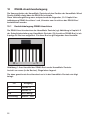
In jeder Menüebene gibt es einen Menüpunkt „Back“ mit dem Sie aus dem aktuellen
Untermenü eine Ebene zurück springen können.
Die nachfolgende Übersicht skizziert das Bedienmenü der Zentrale im unteren Teil
des Gerätedisplays:
Navigation
MENU
OK
8
+
-
6.2
Anlernen
Beim Anlernen beachten Sie bitte, dass Sie einen Mindestabstand der Geräte zur Zentrale von mindestens 50cm einhalten.
Um Geräte an die Zentrale anzulernen können Sie die Zentrale direkt über die Bedien
tasten in den Anlernmodus versetzen. Dazu halten Sie eine der beiden Pfeiltasten
mindestens 5 Sekunden gedrückt. Die Zentrale wechselt dann für 60 Sekunden in
den Anlernmodus. Im Display der Zentrale wird die verbleibende Anlernzeit heruntergezählt. Sie können den Anlernmodus mit der „MENU/OK“-Taste jederzeit beenden.
Zum Abschluss des Anlernmodus wird die Anzahl der neu angelernten Geräte im
Display angezeigt („# new devices“). Die so angelernten Geräte können nun mithilfe
der Zentralensoftware (Dokumentation auf der beiliegenden CD) konfiguriert werden.
7
Anschluss und Grundeinstellungen
Die Bedienung der HomeMatic-Zentrale erfolgt komfortabel über einen PC mit dem
Sie über einen Internetbrowser auf den Webserver der Zentrale zugreifen. Alle Einstellungen und Bedienfunktionen sind in der Web-Oberfläche der Zentrale verfügbar.
Näheres hierzu entnehmen Sie bitte der Dokumentation auf der CD.
Auf der mitgelieferten CD finden Sie eine Schnellanleitung zum Verbinden der Zentrale mit einem Computer und zur Integration in ein Netzwerk.
Um mit der Software auf der HomeMatic-Zentrale interagieren zu können muss zunächst
eine Verbindung zur Zentrale aufgebaut werden. Dies kann auf zwei Wegen geschehen:
• USB-Verbindung
• Netzwerkverbindung
Sollten Sie kein Computer-Netzwerk installiert haben (Router, Switch), ist die Verbindung über USB empfehlenswert.
Die benötigten Verbindungskabel für beide Installationsarten sind der Zentrale beigefügt.
7.1
Inhalt der mitgelieferten CD
Auf der CD befinden sich folgende Daten, durch die Sie durch ein interaktives Menü
geführt werden:
•
•
•
•
•
•
HomeMatic Systempräsentation
HomeMatic Dokumentation (zu den Systemkomponenten, der
Benutzeroberfläche und Systemhandbuch)
USB-Treiber (Interaktive Installation)
„Schritt für Schritt“ Einrichtung USB
„Schritt für Schritt“ Einrichtung LAN (DHCP)
Lizenzbedingungen
9
• Installation Mozilla Firefox
• Installation Adobe Acrobat Reader
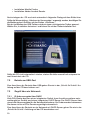
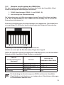
Nach einlegen der CD erscheint automatisch folgender Dialog auf dem Bildschirm.
Sollte die Warnmeldung „Unbekannter Herausgeber“ angezeigt werden, bestätigen Sie
die Meldung durch Drücken auf den Button „Ausführen“.
Bei der Installation des USB-Treibers wird vor einem nichtsignierten Treiber gewarnt.
Wählen Sie „Installation fortsetzen“ und fahren Sie mit der Treiberinstallation fort.
Sollte die CD nicht automatisch starten, starten Sie bitte manuell mit setup.exe im
root-Verzeichnis der CD.
7.2
Betrieb am USB-Port
Zum Anschluss der Zentrale über USB gehen Sie wie in der „Schritt für Schritt“ Anleitung auf der CD beschrieben von!
7.3
Zugriff über ein Netzwerk
7.3.1 IP-Adressvergabe über DHCP
Viele DSL-Router besitzen einen integrierten Switch (zum Anschluss weiterer netzwerktauglicher Geräte) und einem integrierten DHCP-Server. Der DHCP-Server übernimmt die Adressvergabe für die Netzwerkteilnehmer. Als Endanwender bekommen
Sie davon nichts mit! Die Zuweisung erfolgt automatisch.
Zum Anschluss der Zentrale an ein Netzwerk mit DHCP-Server gehen Sie wie in der
„Schritt für Schritt“ Anleitung auf der CD beschrieben vor!
10
7.3.2 Zugriff mit fester IP-Adresse
Steht kein DHCP-Server zur Verfügung oder soll fest eine IP-Adresse vergeben werden,
können Sie dies über das Menü der Zentrale unter dem Menüpunkt „Network“ tun.
Beachten Sie beim Einstellen der IP-Adresse auch die Vergabe der Subnetzmaske und des Standardgateways.
7.3.3 UpnP
Die Zentrale verhält sich wie ein UpnP „Basic Device“. Sie bietet keine Dienste an, sie
beantwortet lediglich UpnP Recovery-Anfragen. Falls auf Ihrem PC der UpnP-Dienst
installiert ist und die Zentrale eine gültige IP-Adresse besitzt, wird die Zentrale als
„HomeMatic Central“ erkannt und in der Netzwerkumgebung als Symbol dargestellt.
Doppelkick auf das Zentralensymbol öffnet die Einstiegsseite der Benutzeroberfläche.
7.4
Zugriff über das WebUI der Zentrale
Nach der Adressvergabe können Sie die Oberfläche der HomeMatic-Zentrale über einen
Browser aufrufen. Dazu geben Sie in die Adresszeile die IP-Adresse der Zentrale ein.
Es erscheint der Anmeldebildschirm. Informationen zum weiteren Vorgehen entnehmen Sie bitte der Anleitung zum WebUI auf der CD.
8
Wartung und Reinigung
Das Produkt ist für Sie bis auf einen eventuell erforderlichen Batteriewechsel wartungsfrei. Überlassen Sie eine Wartung oder Reparatur einer Fachkraft. Reinigen Sie das
Produkt mit einem weichen, sauberen, trockenen und fusselfreien Tuch.
Für die Entfernung von stärkeren Verschmutzungen kann das Tuch leicht mit lauwarmem
Wasser angefeuchtet werden. Verwenden Sie keine lösemittelhaltigen Reinigungsmittel,
das Kunststoffgehäuse und die Beschriftung kann dadurch angegriffen werden.
9
Technische Daten
Funkfrequenz: Typ. Freifeldreichweite: Stromversorgung:
Notversorgung:
868,3MHz
100-300m (je nach Funkpartner)
Steckernetzteil 7,5V DC, 1A
4x LR6 (Mignon)
Schutzart:
Gehäuse:
Gehäusefarbe:
Display:
Abmessungen:
IP20
ABS
Reinweiss, Blende Silber oder Schwarz, Blende Schwarz
LC-Display 60 x 38 mm (hinterleuchtet)
210 x 135 x 38 mm (H x B x T)
(ohne Antenne/Standfuß/Wandhalter)
Gewicht:
430g (ohne Batterien)
11
10
RS485-Anschlussbelegung
Die Kommunikation der HomeMatic Zentrale mit den Geräten der HomeMatic Wired
Familie (HMW) erfolgt über die RS485 Schnittstelle.
Diese Verbindungsleitung muss entsprechend der folgenden „10.1 Kapitel Kontaktbelegung RS485-Anschluss“ und „Hinweise zum Anschluss des RS485-Bus“
konfektioniert werden.
10.1
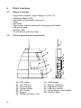
Kontaktebelegung RS485-Anschluss
Die RS485-Anschlussbuchse der HomeMatic Zentrale (vgl. Abbildung in Kapitel 4.2
der Schnellstartanleitung zur HomeMatic Zentrale: (G) Anschluss RS485‑Bus) ist als
8-polige RJ-Buchse ausgeführt. Für diese Buchse gilt folgendes Anschlussbild:
8 ...
... 1
Abbildung 1: Anschlussbild der RS485-Buchse der HomeMatic Zentrale.
Ansicht von vorne (in die Buchse), Riegel oben liegend.
Die oben gezeichnete Anschlussbuchse ist in der HomeMatic Zentrale wie folgt
belegt:
Pin
Belegung
1
RS485 - A
2
RS485 - B
3-8
nicht belegt
Schirmung
Masse - GND
12
10.2
Hinweise zum Anschluss des RS485-Bus
Für den Anschluss der HomeMatic Zentrale an die Geräte der HomeMatic Wired
Familie sind folgende Verbindungen herzustellen:
1. RS485-Signalleitungen (RS485 – A und RS485 – B)
2. Abschirmung bzw. Masseverbindung
Die Verbindung muss mit Hilfe eines abgeschirmten Twisted-Pair-Kabels erfolgen
(z. B. über ein handelsübliches Cat-5-Kabel oder Cat-6-Kabel), wie es aus der PCNetzwerktechnik bekannt ist.
Eine bereits konfektionierte Anschlussleitungen (ein sogenanntes. Patchkabel) bzw.
ein zugehöriger RJ-45 Stecker besitzt dementsprechend folgende Pinanordnung:
1 ...
... 8
Abbildung 2: Anschlussbild 8-poliger Modularstecker.
Ansicht von vorne (auf die Steckkontakte), Riegel oben liegend.
Stellen Sie folgende zeilenweise aufgelisteten Verbindungen her, um die HomeMatic
Zentrale mit den HomeMatic Wired Geräten zu verbinden:
Ader der
Anschlussleitung bzw.
Steckerpin
1
Funktion
Anschluss an
HomeMatic Wired Gerät
Signalleitung RS485 - A
RS485 - A
RS485 - B
2
Signalleitung RS485 - B
3-8
nicht belegt
Schirmung
Masse
GND
Die Verbindung der Abschirmung zum GND-Anschluss der HomeMatic
Wired Geräte ist wichtig, da es sonst aufgrund von Potentialverschiebungen
zu Fehlfunktionen kommen kann.
13
Entsorgungshinweis:
Gerät nicht im Hausmüll entsorgen! Elektronische Geräte sind entsprechend
der Richtlinie über Elektro- und Elektronik-Altgeräte über die örtlichen Sammelstellen für Elektronik-Altgeräte zu entsorgen.
Das CE-Zeichen ist ein Freiverkehrszeichen, das sich ausschließlich an die
Behörden wendet und keine Zusicherung von Eigenschaften beinhaltet.
14
15
Table of Contents
1
Information concerning these instructions . . . . . . . . . . . . . . . . . . . . . . . . . . . 17
2
General system information on HomeMatic . . . . . . . . . . . . . . . . . . . . . . . . . . 17
3
General information on radio operation . . . . . . . . . . . . . . . . . . . . . . . . . . . . . . 17
4
Short overview . . . . . . . . . . . . . . . . . . . . . . . . . . . . . . . . . . . . . . . . . . . . . . . . . 18
4.1
Scope of delivery . . . . . . . . . . . . . . . . . . . . . . . . . . . . . . . . . . . . . . . . . . . . . . . 18
4.2
Control elements and connections . . . . . . . . . . . . . . . . . . . . . . . . . . . . . . . . . 18
4.3
Connecting the power supply and inserting the batteries . . . . . . . . . . . . . . . 19
4.4
Requirements on the computer used for operating the Central . . . . . . . . . . . 19
5
Installation . . . . . . . . . . . . . . . . . . . . . . . . . . . . . . . . . . . . . . . . . . . . . . . . . . . . . 20
5.1
As a standing unit . . . . . . . . . . . . . . . . . . . . . . . . . . . . . . . . . . . . . . . . . . . . . . . 20
5.2
Wall mount . . . . . . . . . . . . . . . . . . . . . . . . . . . . . . . . . . . . . . . . . . . . . . . . . . . . . 20
6
Simple operating functions on the device . . . . . . . . . . . . . . . . . . . . . . . . . . . . 21
6.1
Device settings . . . . . . . . . . . . . . . . . . . . . . . . . . . . . . . . . . . . . . . . . . . . . . . . . 21
6.2
Teaching . . . . . . . . . . . . . . . . . . . . . . . . . . . . . . . . . . . . . . . . . . . . . . . . . . . . . . 22
7
Connection and basic settings . . . . . . . . . . . . . . . . . . . . . . . . . . . . . . . . . . . . . 22
7.1
Content of the provided CD . . . . . . . . . . . . . . . . . . . . . . . . . . . . . . . . . . . . . . . 22
7.2
Operation on the USB port . . . . . . . . . . . . . . . . . . . . . . . . . . . . . . . . . . . . . . . . 23
7.3
Access via a network . . . . . . . . . . . . . . . . . . . . . . . . . . . . . . . . . . . . . . . . . . . . 23
7.3.1 IP address assignment via DHCP . . . . . . . . . . . . . . . . . . . . . . . . . . . . . . . . . . 23
7.3.2 Access with a permanent IP address . . . . . . . . . . . . . . . . . . . . . . . . . . . . . . . 24
7.3.3 UpnP . . . . . . . . . . . . . . . . . . . . . . . . . . . . . . . . . . . . . . . . . . . . . . . . . . . . . . . . . 24
7.4
Access via the WebUI of the Central . . . . . . . . . . . . . . . . . . . . . . . . . . . . . . . . 24
8
Maintenance and cleaning . . . . . . . . . . . . . . . . . . . . . . . . . . . . . . . . . . . . . . . . 24
9
Technical specifications . . . . . . . . . . . . . . . . . . . . . . . . . . . . . . . . . . . . . . . . . . 24
10
RS485 connections . . . . . . . . . . . . . . . . . . . . . . . . . . . . . . . . . . . . . . . . . . . . . . 25
10.1 Pin-outs for the RS485 connection . . . . . . . . . . . . . . . . . . . . . . . . . . . . . . . . . 25
10.2 Information on connecting the RS485 bus . . . . . . . . . . . . . . . . . . . . . . . . . . . 26
16
1
Information concerning these instructions
Read these instructions carefully before beginning operation with your HomeMatic
components.
Keep the instructions handy for later consultation!
Please hand-over the operating manual as well when you hand-over the device to
other persons for use.
Symbols used:
Attention! This indicates a hazard.
Note. This section contains additional important information!
2
General system information on HomeMatic
This device is a part of the HomeMatic home control system and works with the
bidirectional BidCoS® wireless protocol.
All devices are delivered in a standard configuration. The functionality of the device
can also be configured with a programming device and software. Further resulting
functionality and the additional functions provided in the HomeMatic system combined with other components are described in the separate Configuration Instructions and in the HomeMatic System Manual.
All current technical documents and updates are provided under www.HomeMatic.com.
3
General information on radio operation
The radio transmission is on a non-exclusive transmission path which
means that there is a possibility of interference occurring.
Other interfering sources can be caused by switching operations, electrical
motors or defective electrical devices.
The range of transmission within buildings can greatly deviate from open air dis
tances. Besides the transmitting power and the reception characteristics of the
receiver, environmental influences such as humidity in the vicinity and local
structures also play an important role.
Note on ErP directive:
The device must not be put in an Off or Standby condition, because this is
not compatible with its intended use.
Hereby eQ-3 Entwicklung GmbH, declares that this device conforms with the essential requirements and other relevant regulations of Directive 1999/5/EC.
The full declaration of conformity is provided under www.HomeMatic.com.
17
4
Short overview
4.1
Scope of delivery
•
•
•
•
•
•
•
•
•
4.2
18
Plug-in mains adapter (Output voltage 7.5 V DC, 1 A)
4 Batteries Mignon (LR6)
Side-plate for covering the connections
Stand
Wall holder
Three screws and three dowels for fastening the wall holder
USB device cable
Ethernet cable
CD with drivers and instructions
Control elements and connections
(A) – LED "Alarm"
(B) – LED "Service"
(C) – Device display (D) – Control buttons
(E) – LED “Power” (F) – Antenna
(G) – RS485 connection – Bus
(H) – Reset button
(I) – Ethernet connection
(J) – USB device socket
(K) – USB-Host sockets
(L) – Socket plug-in mains adapter
(M) - Battery cabinet
4.3
Connecting the power supply and inserting the batteries
Insert the provided batteries into the Central with proper polarity.
The batteries only serve in buffering the Central if the mains power fails. The
Central is not suitable for continued battery operation.
Connect the provided plug-in adapter to the Central (socket for DC-plug on the side
of the Central (L)).
The green LED "Power" is permanently illuminated if the Central is provided
with power via the plug-in adapter. This LED will flash green if the batteries are supplying the power to the Central. If the Central is operating on
the plug-in adapter without any batteries installed, the yellow "Service" LED will be
illuminated.
As soon as the Central is supplied with power (after inserting the batteries), the Central begins with the boot process. This takes approx. 45 seconds. During the boot
procedure, the yellow LED "Service" flashes.
Caution! Danger of explosion if battery is replaced improperly.
Used batteries are not to be disposed of with the house-hold waste!
Please dispose them at your local battery collection point!
4.4
Requirements on the computer used for operating the
Central
Installing the "HomeMatic WebUI" software is not required. This Web application is
installed on the HomeMatic Central and runs there, independent of the connected
PC. Only the display and access to the operating functions is does via the Internet
Browser that is normally already installed on the user PC (e.g. Microsoft® Internet
Explorer 7 (or higher), Mozilla Firefox® 2 (or higher)).
If there is no Browser installed on your PC, please install the Web-Browser Mozilla
Firefox® from the CD provided according to the instructions in the WebUI operating
instructions.
The HomeMatic WebUI asks for minimum system requirements and offers recommendations for the configuration depending on the system so that the user interface
can be used optimally.
19
1. Recommended screen resolution
a. with PC usage:
i. User screens:
1024 x 768
ii. Guest screens
1024 x 768
iii. Administrator screens:1280 x 1024
b. for PDA use:
i. User screens:
240 x 320
2. Web browser
a. Mozilla Firefox® 2 (or higher) or
b. Microsoft® Internet Explorer 7 (or higher)
3. Data connection
a. Ethernet or
b. USB
i. USB 1.1 (or higher)
ii. Microsoft® Windows® 2000 / XP /Vista™
The same system requirements apply for using the provided CD.
5
Installation
5.1
As a standing unit
In order to use the Central as a standing unit, mount the provided stand on the
underside of the Central. This requires pushing the stand fully into the groove on the
underside of the Central, from the rear, until it rests against the stop.
5.2
Wall mount
Use the provided screws to fasten the provided wall holder at a height on the wall
that you find suitable (the side with only one hole and a tab to the top).
20
6
Simple operating functions on the device
6.1
Device settings
Use the three control buttons on the Central to make the Central device settings
• Network settings
• Time and date settings
• Settings for the Central display
Three control buttons are provided for navigating in the control menu of the Central.
They are assigned as follows:
• Arrow buttons: Navigation in a menu level and for changing value entries (+/-)
• "MENU/OK": Confirming an entry and moving to a sub-menu
Each menu level has a menu point "Back" to jump back one level from the current
sub-menu.
The following overview shows the control menu of the Central in the lower portion of
the device display:
Navigation
MENU
OK
+
-
21
6.2
Teaching
When teaching, make sure that the device is situated at least 50 cm from the
Central.
To add devices (teach) to the Central, you can set the Central to Teach mode directly
through the control buttons. This requires holding one of the two arrow buttons
down for at least 5 seconds. The Central then switches to teach mode for 60 seconds. The remaining teach time is counted down on the display of the Central. You
can end teach mode at any time by pressing the "MENU/OK" button.
Teach mode is completed by indicating the number of newly added devices on the
display ("# new devices"). Devices that have been added in this way can now be
configured using the Central software (documentation on the provided CD).
7
Connection and basic settings
Controlling the HomeMatic Central is done comfortably from a PC with access to the
Central Web-server via your Internet browser. All settings and control functions are
available on the Web-interface of the Central. More information can be found in the
documentation on the CD.
The provided CD contains short guidelines on connecting the Central with a computer and for integration in a network.
In order to interact with the software on a HomeMatic Central, a connection must first be
made with the Central. This can be done in two different ways:
• USB connection
• Network connection
If you haven't installed a computer network (router, switch), the connection via USB
is recommended.
The required connection cables are provided with the Central for both installation types.
7.1
Content of the provided CD
The following data that provides you with an interactive menu is found on the CD:
• HomeMatic System presentation
• HomeMatic documentation (on the system components, the user interface
and the system manual)
• USB driver (Interactive installation)
• "Step by step" USB installation
• "Step by step" LAN installation (DHCP)
• License conditions
• Installation of Mozilla Firefox
• Installation of the Adobe Acrobat Reader
22
After inserting the CD, the following dialog automatically appears on the screen.
If the warning message "Unknown publisher" appears, acknowledge the message by
pressing the "Execute" button.
When installing the USB driver, a warning concerning unsigned drivers is given. Select
"Continue installation" and continue with the driver installation.
If the CD does not start automatically, start it manually using setup.exe from the root
directory of the CD.
7.2
Operation on the USB port
Follow the "Step by step" instructions on the CD for connecting the Central using
the USB!
7.3
Access via a network
7.3.1 IP address assignment via DHCP
Many DSL routers have an integrated switch (for connecting other network-capable
devices) and an integrated DHCP server. The DHCP server handles the address-assignment for the network participants. As end user, you will not notice any of this!
The assignment is made automatically.
Follow the "Step by step" instructions on the CD for connecting the Central to a
network using the DHCP server!
23
7.3.2 Access with a permanent IP address
If no DHCP server is available or if a permanent IP address should be assigned, this
can be done through the "Network" menu point from the Central menu.
When setting the IP address, pay attention to the setting for the subnet
mask and the standard gateway as well.
7.3.3 UpnP
The Central behaves as a UpnP "Basic Device". It does not offer a service, it only
answers UpnP Recovery queries. If the UpnP service is installed on your PC and the
Central has a valid IP address, the Central is recognized as a "HomeMatic Central"
and is shown in the network environment as a symbol. A double click on the Central
symbol opens the start screen for the user interface.
7.4
Access via the WebUI of the Central
After assigning the address, you can call up the interface of the HomeMatic Central
through a Browser. This is done by entering the IP address of the Central in the address
line.
At first, the login screen appears. For information on how to proceed further, please
read the instructions on the WebUI on the CD.
8
Maintenance and cleaning
The product is maintenance-free besides possibly requiring a battery change. Maintenance or repairs are only to be done by trained professionals. Clean the product using a
soft, clean, dry and lint-free cloth.
To remote heavier contamination, make the cloth damp with lukewarm water. Cleaning
agents that contain solvents are not to be used because it can harm the plastic housing
and the labels.
9
Technical specifications
Radio frequency: Typ. outdoor range: Power supply:
Emergency backup supply:
868.3MHz
100-300m (depending on the partner)
Plug-in mains adapter 7.5V DC, 1A
4x LR6 (Mignon)
Protection type:
Housing:
Housing color:
Display:
Dimensions:
IP20
ABS
Pure white, silver faceplate, black faceplate
LC display 60 x 38 mm (backlit)
210 x 135 x 38 mm (H x B x T)
(without antenna/stand/wall holder)
Weight:
430g (without batteries)
24
10
RS485 connections
HomeMatic Central communication with the devices of the HomeMatic Wired family
(HMW) is all done via the RS485 interface.
The connecting lines must be constructed in accordance with the information provided in the following sections "10.1 Pin-outs for the RS485 connection" and "Information on connecting the RS485 bus".
10.1
Pin-outs for the RS485 connection
The RS485 socket connector for the HomeMatic Central (see figure in chapter 4.2 of
the Quick-start instructions for the HomeMatic Central: (G) RS485 bus connection) is
an 8 pin RJ-socket. The following connection diagram applies for this socket:
Figure 1: Connection diagram for the HomeMatic Central RS485 socket.
View from front (into the socket), catch above.
The pin-outs of the connection socket above are assigned as follows in the HomeMatic Central:
Pin
Assignment
1
RS485 - A
2
RS485 - B
3-8
not connected
Shielding
Ground - GND
25
10.2
Information on connecting the RS485 bus
The following connections are to be made for connecting the HomeMatic Central to
devices of the HomeMatic Wired family:
1. RS485 signal lines (RS485 – A and RS485 – B)
2. Shielding or ground connection
The connection requires a shielded twisted-pair cable (e.g. either standard Cat-5
cable or Cat-6 cable), such as is normally used for PC networks.
A prefabricated connecting cable (a so-called patch cable) or a respective RJ-45
plug has the following pin assignments respectively:
1 ...
... 8
Figure 2: 8-pin modular plug connection diagram
View from front (into the plug contacts), catch above.
Make the following connections, as listed, to connect the HomeMatic Central with
the HomeMatic Wired devices.
Wires of the Connection
cable or plug pins
1
Funktion
Connection to the
HomeMatic Wired device
Signal line RS485 - A
RS485 - A
RS485 - B
2
Signal line RS485 - B
3-8
not connected
Shielding
Ground
GND
The connection of the shielding to the GND connection of the HomeMatic
Wired device is important because faulty functionality can be caused by
potential shifting otherwise.
26
Instructions for disposal:
Do not dispose off the device as part of household garbage! Electronic devices
are to be disposed of in accordance with the guidelines concerning electrical
and electronic devices via the local collecting point for old electronic devices.
The CE sign is a free trade sign addressed exclusively to the authorities and
does not include any warranty of any properties.
27
eQ-3 AG
Maiburger Straße 29
D-26789 Leer
www.eQ-3.com