1
General-Purpose AC Servo
J3 Series
Built-in Positioning Function
MODEL
MODEL
CODE
HEAD OFFICE : TOKYO BLDG MARUNOUCHI TOKYO 100-8310
SH (NA) 030058-E (0806) MEE
Printed in Japan
This Instruction Manual uses recycled paper.
Specifications subject to change without notice.
J3 Series MR-J3- T Servo Amplifier Instruction Manual (CC-Link) E
MODEL
MR-J3- T
SERVO AMPLIFIER
INSTRUCTION MANUAL
(CC-Link)
E
Safety Instructions
(Always read these instructions before using the equipment.)
Do not attempt to install, operate, maintain or inspect the servo amplifier and servo motor until you have read
through this Instruction Manual, Installation guide, Servo motor Instruction Manual (Vol.2) and appended
documents carefully and can use the equipment correctly. Do not use the servo amplifier and servo motor until
you have a full knowledge of the equipment, safety information and instructions.
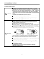
In this Instruction Manual, the safety instruction levels are classified into "WARNING" and "CAUTION".
WARNING
Indicates that incorrect handling may cause hazardous conditions,
resulting in death or severe injury.
CAUTION
Indicates that incorrect handling may cause hazardous conditions,
resulting in medium or slight injury to personnel or may cause physical
damage.
Note that the CAUTION level may lead to a serious consequence according to conditions. Please follow the
instructions of both levels because they are important to personnel safety.
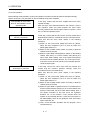
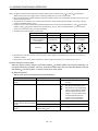
What must not be done and what must be done are indicated by the following diagrammatic symbols.
: Indicates what must not be done. For example, "No Fire" is indicated by
: Indicates what must be done. For example, grounding is indicated by
.
.
In this Instruction Manual, instructions at a lower level than the above, instructions for other functions, and so
on are classified into "POINT".
After reading this installation guide, always keep it accessible to the operator.
A- 1
1. To prevent electric shock, note the following
WARNING
Before wiring or inspection, turn off the power and wait for 15 minutes or more until the charge lamp turns
off. Then, confirm that the voltage between P( ) and N( ) is safe with a voltage tester and others.
Otherwise, an electric shock may occur. In addition, always confirm from the front of the servo amplifier,
whether the charge lamp is off or not.
Connect the servo amplifier and servo motor to ground.
Any person who is involved in wiring and inspection should be fully competent to do the work.
Do not attempt to wire the servo amplifier and servo motor until they have been installed. Otherwise, you
may get an electric shock.
Operate the switches with dry hand to prevent an electric shock.
The cables should not be damaged, stressed, loaded, or pinched. Otherwise, you may get an electric
shock.
During power-on or operation, do not open the front cover of the servo amplifier. You may get an electric
shock.
Do not operate the servo amplifier with the front cover removed. High-voltage terminals and charging area
are exposed and you may get an electric shock.
Except for wiring or periodic inspection, do not remove the front cover even of the servo amplifier if the
power is off. The servo amplifier is charged and you may get an electric shock.
2. To prevent fire, note the following
CAUTION
Install the servo amplifier, servo motor and regenerative resistor on incombustible material. Installing them
directly or close to combustibles will lead to a fire.
Always connect a magnetic contactor (MC) between the main circuit power supply and L1, L2, and L3 of
the servo amplifier, and configure the wiring to be able to shut down the power supply on the side of the
servo amplifier’s power supply. If a magnetic contactor (MC) is not connected, continuous flow of a large
current may cause a fire when the servo amplifier malfunctions.
When a regenerative resistor is used, use an alarm signal to switch main power off. Otherwise, a
regenerative transistor fault or the like may overheat the regenerative resistor, causing a fire.
3. To prevent injury, note the follow
CAUTION
Only the voltage specified in the Instruction Manual should be applied to each terminal, Otherwise, a
burst, damage, etc. may occur.
Connect the terminals correctly to prevent a burst, damage, etc.
Ensure that polarity (
,
) is correct. Otherwise, a burst, damage, etc. may occur.
Take safety measures, e.g. provide covers, to prevent accidental contact of hands and parts (cables, etc.)
with the servo amplifier heat sink, regenerative resistor, servo motor, etc. since they may be hot while
power is on or for some time after power-off. Their temperatures may be high and you may get burnt or a
parts may damaged.
During operation, never touch the rotating parts of the servo motor. Doing so can cause injury.
A- 2
4. Additional instructions
The following instructions should also be fully noted. Incorrect handling may cause a fault, injury, electric shock,
etc.
(1) Transportation and installation
CAUTION
Transport the products correctly according to their weights.
Stacking in excess of the specified number of products is not allowed.
Do not carry the servo motor by the cables, shaft or encoder.
Do not hold the front cover to transport the servo amplifier. The servo amplifier may drop.
Install the servo amplifier in a load-bearing place in accordance with the Instruction Manual.
Do not climb or stand on servo equipment. Do not put heavy objects on equipment.
The servo amplifier and servo motor must be installed in the specified direction.
Leave specified clearances between the servo amplifier and control enclosure walls or other equipment.
Do not install or operate the servo amplifier and servo motor which has been damaged or has any parts
missing.
Provide adequate protection to prevent screws and other conductive matter, oil and other combustible
matter from entering the servo amplifier and servo motor.
Do not drop or strike servo amplifier or servo motor. Isolate from all impact loads.
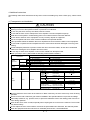
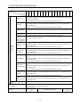
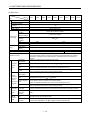
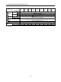
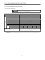
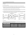
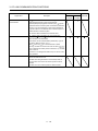
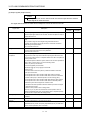
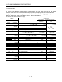
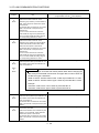
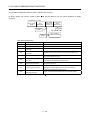
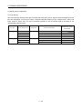
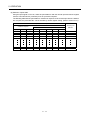
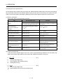
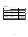
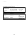
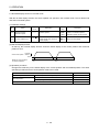
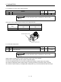
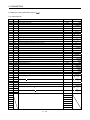
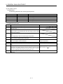
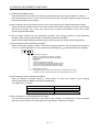
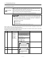
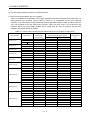
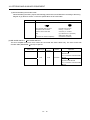
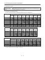
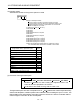
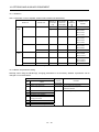
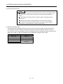
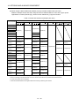
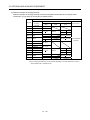
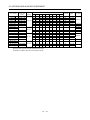
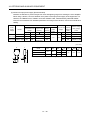
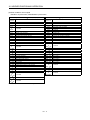
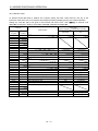
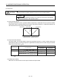
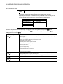
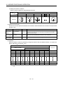
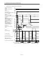
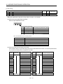
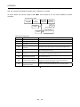
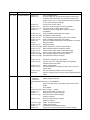
When you keep or use it, please fulfill the following environmental conditions.
Conditions
Environment
Ambient
temperature
Ambient
humidity
In operation
In storage
Servo amplifier
Servo motor
[
]
0 to 55 (non-freezing)
0 to 40 (non-freezing)
[
]
32 to 131 (non-freezing)
32 to 104 (non-freezing)
[
]
20 to 65 (non-freezing)
[
]
4 to 149 (non-freezing)
15 to 70 (non-freezing)
5 to 158 (non-freezing)
In operation
90%RH or less (non-condensing)
In storage
90%RH or less (non-condensing)
80%RH or less (non-condensing)
Ambience
Indoors (no direct sunlight) Free from corrosive gas, flammable gas, oil mist, dust and dirt
Altitude
Max. 1000m (3280 ft) above sea level
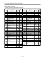
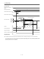
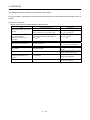
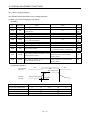
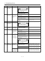
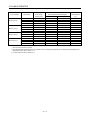
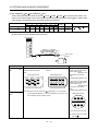
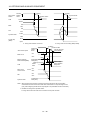
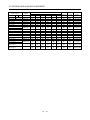
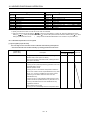
HF-MP series
HF-KP series
HF-SP51 81
HF-SP52 to 152
HF-SP524 to 1524
HC-RP Series
HC-UP72 152
HF-SP202 352
HF-SP121 201
HC-UP202 to 502
HF-SP2024 3524
HF-SP301 421
HF-SP502 702
HF-SP5024 7024
5.9 or less
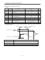
HC-LP52 to 152
HC-LP202 to 302
HA-LP601 to 12K1
HA-LP701M to 15K1M
HA-LP502 to 22K2
HA-LP6014 to 12K14
HA-LP701M4 to 15K1M4 HA-LP11K24 to 22K24
HA-LP15K1 to 25K1
HA-LP37K1M
HA-LP15K14 to 20K14
HA-LP22K1M4
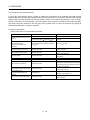
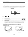
(Note)
Vibration
2
[m/s ]
X Y: 49
X Y: 24.5
X: 24.5 Y: 49
X: 24.5 Y: 29.4
X: 9.8 Y: 24.5
X: 19.6 Y: 49
X: 11.7 Y: 29.4
X Y: 9.8
Note. Except the servo motor with a reduction gear.
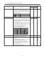
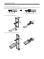
Securely attach the servo motor to the machine. If attach insecurely, the servo motor may come off during
operation.
The servo motor with a reduction gear must be installed in the specified direction to prevent oil leakage.
Take safety measures, e.g. provide covers, to prevent accidental access to the rotating parts of the servo
motor during operation.
Never hit the servo motor or shaft, especially when coupling the servo motor to the machine. The encoder
may become faulty.
Do not subject the servo motor shaft to more than the permissible load. Otherwise, the shaft may break.
When the equipment has been stored for an extended period of time, consult Mitsubishi.
A- 3
(2) Wiring
CAUTION
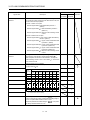
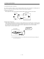
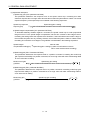
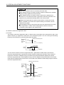
Wire the equipment correctly and securely. Otherwise, the servo motor may operate unexpectedly.
Do not install a power capacitor, surge absorber or radio noise filter (FR-BIF-(H) option) between the
servo motor and servo amplifier.
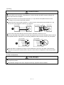
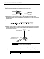
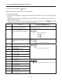
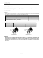
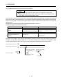
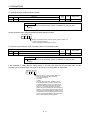
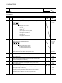
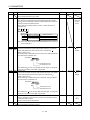
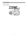
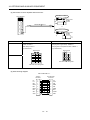
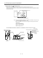
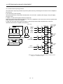
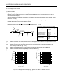
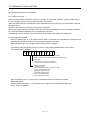
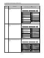
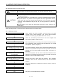
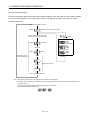
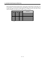
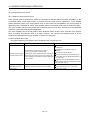
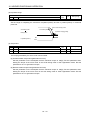
Connect the wires to the correct phase terminals (U, V, W) of the servo amplifier and servo motor.
Not doing so may cause unexpected operation.
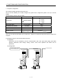
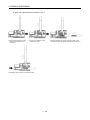
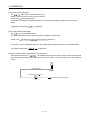
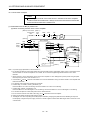
Connect the servo motor power terminal (U, V, W) to the servo motor power input terminal (U, V, W)
directly. Do not let a magnetic contactor, etc. intervene.
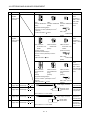
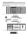
Servo amplifier
U
U
Servo motor
Servo motor
V
V
M
W
W
U
U
V
V
Servo amplifier
M
W
W
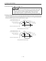
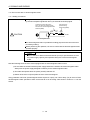
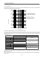
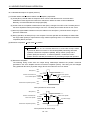
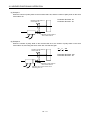
Do not connect AC power directly to the servo motor. Otherwise, a fault may occur.
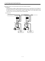
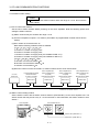
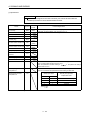
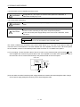
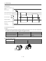
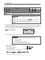
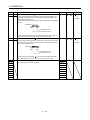
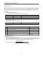
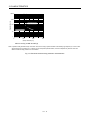
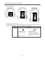
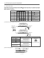
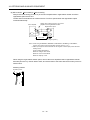
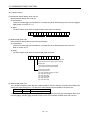
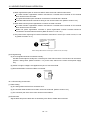
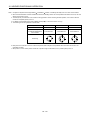
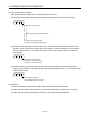
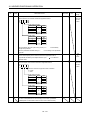
The surge absorbing diode installed on the DC output signal relay of the servo amplifier must be wired in
the specified direction. Otherwise, the forced stop (EMG) and other protective circuits may not operate.
Servo amplifier
Servo amplifier
24VDC
24VDC
DOCOM
DOCOM
DICOM
DICOM
Control
output
signal
Control
output
signal
RA
RA
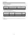
When the cable is not tightened enough to the terminal block (connector), the cable or terminal block
(connector) may generate heat because of the poor contact. Be sure to tighten the cable with specified
torque.
(3) Test run adjustment
CAUTION
Before operation, check the parameter settings. Improper settings may cause some machines to perform
unexpected operation.
The parameter settings must not be changed excessively. Operation will be insatiable.
A- 4
(4) Usage
CAUTION
Provide an external emergency stop circuit to ensure that operation can be stopped and power switched
off immediately.
Any person who is involved in disassembly and repair should be fully competent to do the work.
Before resetting an alarm, make sure that the run signal of the servo amplifier is off to prevent an
accident. A sudden restart is made if an alarm is reset with the run signal on.
Do not modify the equipment.
Use a noise filter, etc. to minimize the influence of electromagnetic interference, which may be caused by
electronic equipment used near the servo amplifier.
Burning or breaking a servo amplifier may cause a toxic gas. Do not burn or break a servo amplifier.
Use the servo amplifier with the specified servo motor.
The electromagnetic brake on the servo motor is designed to hold the motor shaft and should not be used
for ordinary braking.
For such reasons as service life and mechanical structure (e.g. where a ball screw and the servo motor
are coupled via a timing belt), the electromagnetic brake may not hold the motor shaft. To ensure safety,
install a stopper on the machine side.
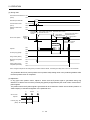
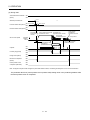
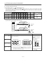
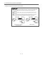
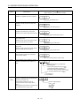
(5) Corrective actions
CAUTION
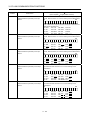
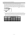
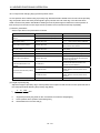
When it is assumed that a hazardous condition may take place at the occur due to a power failure or a
product fault, use a servo motor with an electromagnetic brake or an external brake mechanism for the
purpose of prevention.
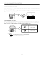
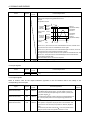
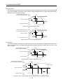
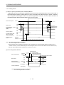
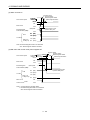
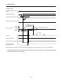
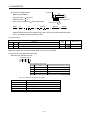
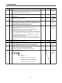
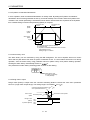
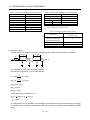
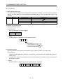
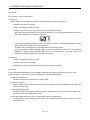
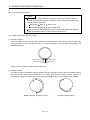
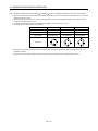
Configure the electromagnetic brake circuit so that it is activated not only by the servo amplifier signals
but also by an external forced stop (EMG).
Contacts must be open when
servo-off, when an trouble (ALM)
and when an electromagnetic brake
interlock (MBR).
SON
Circuit must be
opened during
forced stop (EMG).
RA
EMG
24VDC
Electromagnetic brake
When any alarm has occurred, eliminate its cause, ensure safety, and deactivate the alarm before
restarting operation.
When power is restored after an instantaneous power failure, keep away from the machine because the
machine may be restarted suddenly (design the machine so that it is secured against hazard if restarted).
(6) Maintenance, inspection and parts replacement
CAUTION
With age, the electrolytic capacitor of the servo amplifier will deteriorate. To prevent a secondary accident
due to a fault, it is recommended to replace the electrolytic capacitor every 10 years when used in general
environment. Please consult our sales representative.
A- 5
(7) General instruction
To illustrate details, the equipment in the diagrams of this Specifications and Instruction Manual may have
been drawn without covers and safety guards. When the equipment is operated, the covers and safety
guards must be installed as specified. Operation must be performed in accordance with this
Specifications and Instruction Manual.
About processing of waste
When you discard servo amplifier, a battery (primary battery), and other option articles, please follow the law of
each country (area).
FOR MAXIMUM SAFETY
These products have been manufactured as a general-purpose part for general industries, and have not
been designed or manufactured to be incorporated in a device or system used in purposes related to
human life.
Before using the products for special purposes such as nuclear power, electric power, aerospace,
medicine, passenger movement vehicles or under water relays, contact Mitsubishi.
These products have been manufactured under strict quality control. However, when installing the product
where major accidents or losses could occur if the product fails, install appropriate backup or failsafe
functions in the system.
EEP-ROM life
The number of write times to the EEP-ROM, which stores parameter settings, etc., is limited to 100,000. If
the total number of the following operations exceeds 100,000, the servo amplifier and/or converter unit may
fail when the EEP-ROM reaches the end of its useful life.
Write to the EEP-ROM due to parameter setting changes
Home position setting in the absolute position detection system
Write to the EEP-ROM due to device changes
Write to the EEP-ROM due to point table changes
Precautions for Choosing the Products
Mitsubishi will not be held liable for damage caused by factors found not to be the cause of Mitsubishi;
machine damage or lost profits caused by faults in the Mitsubishi products; damage, secondary damage,
accident compensation caused by special factors unpredictable by Mitsubishi; damages to products other
than Mitsubishi products; and to other duties.
A- 6
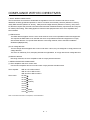
COMPLIANCE WITH EC DIRECTIVES
1. WHAT ARE EC DIRECTIVES?
The EC directives were issued to standardize the regulations of the EU countries and ensure smooth
distribution of safety-guaranteed products. In the EU countries, the machinery directive (effective in January,
1995), EMC directive (effective in January, 1996) and low voltage directive (effective in January, 1997) of the
EC directives require that products to be sold should meet their fundamental safety requirements and carry the
CE marks (CE marking). CE marking applies to machines and equipment into which servo amplifiers have
been installed.
(1) EMC directive
The EMC directive applies not to the servo units alone but to servo-incorporated machines and equipment.
This requires the EMC filters to be used with the servo-incorporated machines and equipment to comply
with the EMC directive. For specific EMC directive conforming methods, refer to the EMC Installation
Guidelines (IB(NA)67310).
(2) Low voltage directive
The low voltage directive applies also to servo units alone. Hence, they are designed to comply with the low
voltage directive.
This servo is certified by TUV, third-party assessment organization, to comply with the low voltage directive.
(3) Machine directive
Not being machines, the servo amplifiers need not comply with this directive.
2. PRECAUTIONS FOR COMPLIANCE
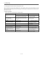
(1) Servo amplifiers and servo motors used
Use the servo amplifiers and servo motors which comply with the standard model.
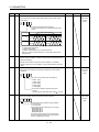
Servo amplifier
Servo motor
:MR-J3-10T to MR-J3-22KT
MR-J3-10T1 to MR-J3-40T1
MR-J3-60T4 to MR-J3-22KT4
:HF-MP
HF-KP
HF-SP (Note)
HF-SP 4 (Note)
HC-RP
HC-UP
HC-LP
HA-LP (Note)
HA-LP 4 (Note)
Note. For the latest information of compliance, contact Mitsubishi.
A- 7
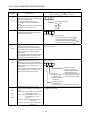
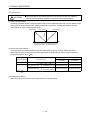
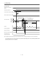
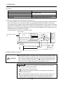
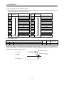
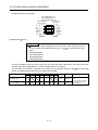
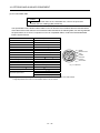
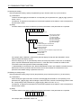
(2) Configuration
The control circuit provide safe separation to the main circuit in the servo amplifier.
Control box
Reinforced
insulating type
No-fuse
breaker
Magnetic
contactor
NFB
MC
24VDC
power
supply
Servo
amplifier
Servo
motor
M
(3) Environment
Operate the servo amplifier at or above the contamination level 2 set forth in IEC60664-1. For this purpose,
install the servo amplifier in a control box which is protected against water, oil, carbon, dust, dirt, etc. (IP54).
(4) Power supply
(a) This servo amplifier can be supplied from star-connected supply with earthed neutral point of
overvoltage category III set forth in IEC60664-1. However, when using the neutral point of 400V class
for single-phase supply, a reinforced insulating transformer is required in the power input section.
(b) When supplying interface power from external, use a 24VDC power supply which has been insulationreinforced in I/O.
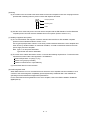
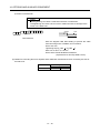
(5) Grounding
(a) To prevent an electric shock, always connect the protective earth (PE) terminals (marked
servo amplifier to the protective earth (PE) of the control box.
(b) Do not connect two ground cables to the same protective earth (PE) terminal (marked
connect the cables to the terminals one-to-one.
) of the
). Always
PE terminals
PE terminals
(c) If a leakage current breaker is used to prevent an electric shock, the protective earth (PE) terminals
(marked ) of the servo amplifier must be connected to the corresponding earth terminals.
A- 8
(6) Wiring
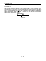
(a) The cables to be connected to the terminal block of the servo amplifier must have crimping terminals
provided with insulating tubes to prevent contact with adjacent terminals.
Crimping terminal
Insulating tube
Cable
(b) Use the servo motor side power connector which complies with the EN Standard. The EN Standard
compliant power connector sets are available from us as options. (Refer to section 14.1)
(7) Auxiliary equipment and options
(a) The no-fuse breaker and magnetic contactor used should be the EN or IEC standard-compliant
products of the models described in section 14.10.
Use a type B (Note) breaker. When it is not used, provide insulation between the servo amplifier and
other device by double insulation or reinforced insulation, or install a transformer between the main
power supply and servo amplifier.
Note. Type A: AC and pulse detectable
Type B: Both AC and DC detectable
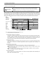
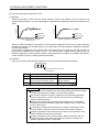
(b) The sizes of the cables described in section 14.9 meet the following requirements. To meet the other
requirements, follow Table 5 and Appendix C in EN60204-1.
Ambient temperature: 40 (104) [°C (°F)]
Sheath: PVC (polyvinyl chloride)
Installed on wall surface or open table tray
(c) Use the EMC filter for noise reduction.
(8) Performing EMC tests
When EMC tests are run on a machine/device into which the servo amplifier has been installed, it must
conform to the electromagnetic compatibility (immunity/emission) standards after it has satisfied the
operating environment/electrical equipment specifications.
For the other EMC directive guidelines on the servo amplifier, refer to the EMC Installation Guidelines
(IB(NA)67310).
A- 9
CONFORMANCE WITH UL/C-UL STANDARD
(1) Servo amplifiers and servo motors used
Use the servo amplifiers and servo motors which comply with the standard model.
Servo amplifier
:MR-J3-10T to MR-J3-22KT
MR-J3-10T1 to MR-J3-40T1
MR-J3-60T4 to MR-J3-22KT4
:HF-MP
HF-KP
HF-SP (Note)
HF-SP 4 (Note)
HC-RP
HC-UP
HC-LP
HA-LP (Note)
HA-LP 4 (Note)
Servo motor
Note. For the latest information of compliance, contact Mitsubishi.
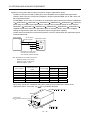
(2) Installation
3
Install a fan of 100CFM (2.8m /min) air flow 4[in] (10.16[cm]) above the servo amplifier or provide cooling
of at least equivalent capability to ensure that the ambient temperature conforms to the environment
conditions (55 or less).
(3) Short circuit rating (SCCR: Short Circuit Current Rating)
Suitable For Use In A Circuit Capable Of Delivering Not More Than 100 kA rms Symmetrical Amperes, 500
Volts Maximum.
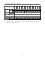
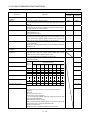
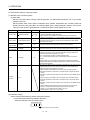
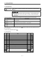
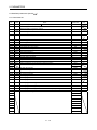
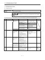
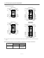
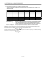
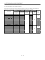
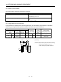
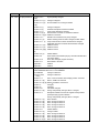
(4) Capacitor discharge time
The capacitor discharge time is as listed below. To ensure safety, do not touch the charging section for 15
minutes after power-off.
Discharge time
Servo amplifier
MR-J3-10T
MR-J3-40T
60T(4)
[min]
20T
1
10T1
20T1
2
MR-J3-70T
3
MR-J3-40T1
4
MR-J3-100T(4)
5
MR-J3-200T(4)
MR-J3-350T4
350T
500T(4)
700T(4)
9
10
MR-J3-11KT(4)
4
MR-J3-15KT(4)
6
MR-J3-22KT(4)
8
A - 10
(5) Options and auxiliary equipment
Use UL/C-UL standard-compliant products.
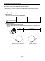
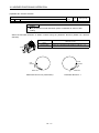
(6) Attachment of a servo motor
For the flange size of the machine side where the servo motor is installed, refer to “CONFORMANCE WITH
UL/C-UL STANDARD” in the Servo Motor Instruction Manual (Vol.2).
(7) About wiring protection
For installation in United States, branch circuit protection must be provided, in accordance with the National
Electrical Code and any applicable local codes.
For installation in Canada, branch circuit protection must be provided, in accordance with the Canada
Electrical Code and any applicable provincial codes.
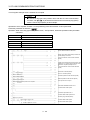
<<About the manuals>>
This Instruction Manual and the MELSERVO Servo Motor Instruction Manual (Vol.2) are required if you use
the General-Purpose AC servo MR-J3-T for the first time. Always purchase them and use the MR-J3-T
safely.
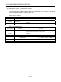
Relevant manuals
Manual name
Manual No.
MELSERVO-J3 Series Instructions and Cautions for Safe Use of AC Servos
IB(NA)0300077
MELSERVO Servo Motor Instruction Manual (Vol.2)
SH(NA)030041
EMC Installation Guidelines
IB(NA)67310
<<About the wires used for wiring>>
Wiring wires mentioned in this instruction manual are selected based on the ambient temperature of 40°C
(104 ).
A - 11
MEMO
A - 12
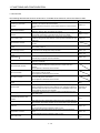
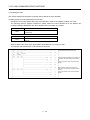
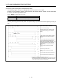
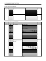
CONTENTS
1. FUNCTIONS AND CONFIGURATION
1 - 1 to 1 -36
1.1 Introduction............................................................................................................................................... 1 - 1
1.1.1 Features of CC-Link communication functions ................................................................................ 1 - 1
1.1.2 Function block diagram..................................................................................................................... 1 - 2
1.1.3 System configuration......................................................................................................................... 1 - 5
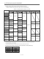
1.2 Servo amplifier standard specifications................................................................................................... 1 - 7
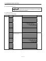
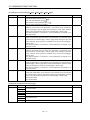
1.3 Function list ............................................................................................................................................. 1 -13
1.4 Model code definition .............................................................................................................................. 1 -15
1.5 Combination with servo motor ................................................................................................................ 1 -16
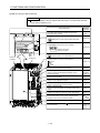
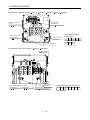
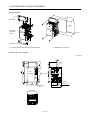
1.6 Structure .................................................................................................................................................. 1 -17
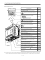
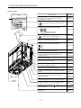
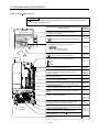
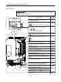
1.6.1 Parts identification ............................................................................................................................ 1 -17
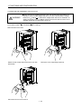
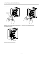
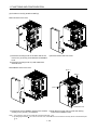
1.6.2 Removal and reinstallation of the front cover.................................................................................. 1 -23
1.7 Configuration including auxiliary equipment .......................................................................................... 1 -26
1.8 Selection of operation method................................................................................................................ 1 -34
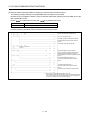
2. INSTALLATION
2 - 1 to 2 - 4
2.1 Installation direction and clearances ....................................................................................................... 2 - 1
2.2 Keep out foreign materials....................................................................................................................... 2 - 3
2.3 Cable stress ............................................................................................................................................. 2 - 3
2.4 Inspection items ....................................................................................................................................... 2 - 4
2.5 Parts having service lives ........................................................................................................................ 2 - 4
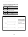
3. CC-LINK COMMUNICATION FUNCTIONS
3 - 1 to 3 -60
3.1 Communication specifications ................................................................................................................. 3 - 1
3.2 System configuration ............................................................................................................................... 3 - 2
3.2.1 Configuration example ...................................................................................................................... 3 - 2
3.2.2 Wiring method ................................................................................................................................... 3 - 3
3.2.3 Station number setting ...................................................................................................................... 3 - 5
3.2.4 Communication baud rate setting..................................................................................................... 3 - 6
3.2.5 Occupied station count setting.......................................................................................................... 3 - 6
3.3 Functions .................................................................................................................................................. 3 - 7
3.3.1 Function block diagram..................................................................................................................... 3 - 7
3.3.2 Functions ........................................................................................................................................... 3 - 7
3.4 Servo amplifier setting ............................................................................................................................. 3 - 8
3.5 I/O signals (I/O devices) transferred to/from the programmable controller CPU ................................... 3 - 9
3.5.1 I/O signals (I/O devices).................................................................................................................... 3 - 9
3.5.2 Detailed explanation of I/O signals .................................................................................................. 3 -12
3.5.3 Monitor codes ................................................................................................................................... 3 -22
3.5.4 Instruction codes (RWwn+2 RWwn+3) ......................................................................................... 3 -23
3.5.5 Respond codes (RWrn+2) ............................................................................................................... 3 -31
3.5.6 Setting the CN6 external input signals ............................................................................................ 3 -32
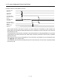
3.6 Data communication timing charts ......................................................................................................... 3 -34
3.6.1 Monitor codes ................................................................................................................................... 3 -34
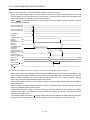
3.6.2 Instruction codes .............................................................................................................................. 3 -36
1
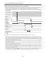
3.6.3 Remote register-based position/speed setting................................................................................ 3 -38
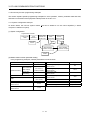
3.7 Function-by-function programming examples........................................................................................ 3 -41
3.7.1 System configuration example......................................................................................................... 3 -41
3.7.2 Reading the servo amplifier status .................................................................................................. 3 -44
3.7.3 Writing the operation commands..................................................................................................... 3 -45
3.7.4 Reading the data .............................................................................................................................. 3 -46
3.7.5 Writing the data ................................................................................................................................ 3 -49
3.7.6 Operation .......................................................................................................................................... 3 -52
3.8 Continuous operation program example................................................................................................ 3 -55
3.8.1 System configuration example when 1 station is occupied ............................................................ 3 -55
3.8.2 Program example when 1 station is occupied ................................................................................ 3 -56
3.8.3 System configuration example when 2 stations are occupied........................................................ 3 -58
3.8.4 Program example when 2 stations are occupied............................................................................ 3 -59
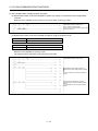
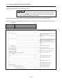
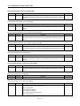
4. SIGNALS AND WIRING
4 - 1 to 4 -54
4.1 Input power supply circuit ........................................................................................................................ 4 - 2
4.2 I/O signal connection diagram ................................................................................................................ 4 -10
4.3 Explanation of power supply system ...................................................................................................... 4 -11
4.3.1 Signal explanations .......................................................................................................................... 4 -11
4.3.2 Power-on sequence ......................................................................................................................... 4 -12
4.3.3 CNP1, CNP2, CNP3 wiring method ................................................................................................ 4 -14
4.4 Connectors and signal arrangements .................................................................................................... 4 -22
4.5 Signal (device) explanation..................................................................................................................... 4 -23
4.5.1 I/O devices........................................................................................................................................ 4 -23
4.5.2 Input signals ..................................................................................................................................... 4 -26
4.5.3 Output signals................................................................................................................................... 4 -26
4.5.4 Power supply.................................................................................................................................... 4 -27
4.6 Detailed description of signals (devices) ................................................................................................ 4 -27
4.6.1 Forward rotation start reverse rotation start temporary stop/restart........................................... 4 -27
4.6.2 Movement completion rough match in position .......................................................................... 4 -28
4.6.3 Torque limit....................................................................................................................................... 4 -30
4.7 Alarm occurrence timing chart................................................................................................................ 4 -31
4.8 Interface................................................................................................................................................... 4 -32
4.8.1 Internal connection diagram ............................................................................................................ 4 -32
4.8.2 Detailed description of interfaces..................................................................................................... 4 -33
4.8.3 Source I/O interfaces ....................................................................................................................... 4 -35
4.9 Treatment of cable shield external conductor ........................................................................................ 4 -36
4.10 Connection of servo amplifier and servo motor ................................................................................... 4 -37
4.10.1 Connection instructions.................................................................................................................. 4 -37
4.10.2 Power supply cable wiring diagrams ............................................................................................. 4 -38
4.11 Servo motor with an electromagnetic brake......................................................................................... 4 -48
4.11.1 Safety precautions ......................................................................................................................... 4 -48
4.11.2 Timing charts .................................................................................................................................. 4 -49
4.11.3 Wiring diagrams (HF-MP series HF-KP series servo motor) ..................................................... 4 -52
4.12 Grounding.............................................................................................................................................. 4 -53
2
5. OPERATION
5 - 1 to 5 -60
5.1 Switching power on for the first time ....................................................................................................... 5 - 1
5.1.1 Startup procedure.............................................................................................................................. 5 - 1
5.1.2 Wiring check ...................................................................................................................................... 5 - 2
5.1.3 Surrounding environment.................................................................................................................. 5 - 3
5.2 Startup ...................................................................................................................................................... 5 - 4
5.2.1 Power on and off procedures............................................................................................................ 5 - 4
5.2.2 Stop.................................................................................................................................................... 5 - 4
5.2.3 Test operation.................................................................................................................................... 5 - 5
5.2.4 Parameter setting .............................................................................................................................. 5 - 6
5.2.5 Point table setting.............................................................................................................................. 5 - 7
5.2.6 Actual operation ................................................................................................................................ 5 - 7
5.3 Servo amplifier display............................................................................................................................. 5 - 8
5.4 Automatic operation mode...................................................................................................................... 5 -10
5.4.1 What is automatic operation mode?................................................................................................ 5 -10
5.4.2 Automatic operation using point table ............................................................................................. 5 -12
5.4.3 Remote register-based position/speed setting................................................................................ 5 -22
5.5 Manual operation mode .......................................................................................................................... 5 -28
5.5.1 JOG operation .................................................................................................................................. 5 -28
5.5.2 Manual pulse generator ................................................................................................................... 5 -29
5.6 Manual home position return mode........................................................................................................ 5 -31
5.6.1 Outline of home position return........................................................................................................ 5 -31
5.6.2 Dog type home position return......................................................................................................... 5 -34
5.6.3 Count type home position return ..................................................................................................... 5 -36
5.6.4 Data setting type home position return............................................................................................ 5 -38
5.6.5 Stopper type home position return .................................................................................................. 5 -39
5.6.6 Home position ignorance (servo-on position defined as home position) ....................................... 5 -41
5.6.7 Dog type rear end reference home position return ......................................................................... 5 -42
5.6.8 Count type front end reference home position return ..................................................................... 5 -44
5.6.9 Dog cradle type home position return ............................................................................................. 5 -46
5.6.10 Dog type first Z-phase reference home position return ................................................................ 5 -48
5.6.11 Dog type front end reference home position return method......................................................... 5 -50
5.6.12 Dogless Z-phase reference home position return method ........................................................... 5 -52
5.6.13 Home position return automatic return function ............................................................................ 5 -54
5.6.14 Automatic positioning function to the home position..................................................................... 5 -55
5.7 Roll feed display function in roll feed mode............................................................................................ 5 -56
5.8 Absolute position detection system ........................................................................................................ 5 -57
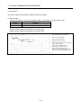
6. PARAMETERS
6 - 1 to 6 -40
6.1 Basic setting parameters (No.PA
)................................................................................................... 6 - 1
6.1.1 Parameter list .................................................................................................................................... 6 - 1
6.1.2 Parameter write inhibit ...................................................................................................................... 6 - 2
6.1.3 Selection of command system.......................................................................................................... 6 - 3
6.1.4 Selection of regenerative option ....................................................................................................... 6 - 3
6.1.5 Using absolute position detection system ........................................................................................ 6 - 4
6.1.6 Follow-up for absolute value command system in incremental system.......................................... 6 - 4
6.1.7 Feeding function selection ................................................................................................................ 6 - 5
3
6.1.8 Electronic gear................................................................................................................................... 6 - 6
6.1.9 Auto tuning ........................................................................................................................................ 6 - 7
6.1.10 In-position range.............................................................................................................................. 6 - 8
6.1.11 Torque limit...................................................................................................................................... 6 - 9
6.1.12 Selection of servo motor rotation direction.................................................................................... 6 -10
6.1.13 Encoder output pulse ..................................................................................................................... 6 -10
6.2 Gain/filter parameters (No. PB
)...................................................................................................... 6 -12
6.2.1 Parameter list ................................................................................................................................... 6 -12
6.2.2 Detail list ........................................................................................................................................... 6 -13
6.3 Extension setting parameters (No. PC
) ......................................................................................... 6 -20
6.3.1 Parameter list ................................................................................................................................... 6 -20
6.3.2 Detail list ........................................................................................................................................... 6 -21
6.3.3 S-pattern acceleration/deceleration................................................................................................. 6 -27
6.3.4 Alarm history clear............................................................................................................................ 6 -27
6.3.5 Rough match output......................................................................................................................... 6 -27
6.3.6 Software limit .................................................................................................................................... 6 -28
6.4 I/O setting parameters (No. PD
)..................................................................................................... 6 -29
6.4.1 Parameter list ................................................................................................................................... 6 -29
6.4.2 Detail list ........................................................................................................................................... 6 -30
6.4.3 Stopping method when the forward stroke end (LSP) or reverse stroke end (LSN) is valid......... 6 -38
6.4.4 Stopping method when a software limit is detected........................................................................ 6 -39
7. MR Configurator
7 - 1 to 7 -26
7.1 Specifications ........................................................................................................................................... 7 - 1
7.2 System configuration ............................................................................................................................... 7 - 2
7.3 Station selection ....................................................................................................................................... 7 - 4
7.4 Parameters ............................................................................................................................................... 7 - 5
7.5 Point table................................................................................................................................................. 7 - 7
7.6 Device assignment method ..................................................................................................................... 7 - 9
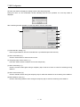
7.7 Test operation ......................................................................................................................................... 7 -13
7.7.1 Jog operation.................................................................................................................................... 7 -13
7.7.2 Positioning operation........................................................................................................................ 7 -15
7.7.3 Motor-less operation ........................................................................................................................ 7 -18
7.7.4 Output signal (DO) forced output..................................................................................................... 7 -19
7.7.5 Single-step feed ............................................................................................................................... 7 -20
7.8 Alarm ....................................................................................................................................................... 7 -23
7.8.1 Alarm display .................................................................................................................................... 7 -23
7.8.2 Batch display of data at alarm occurrence ...................................................................................... 7 -24
7.8.3 Alarm history..................................................................................................................................... 7 -26
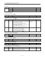
8. PARAMETER UNIT (MR-PRU03)
8 - 1 to 8 -20
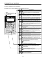
8.1 External appearance and key explanations ............................................................................................ 8 - 2
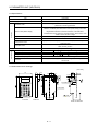
8.2 Specifications ........................................................................................................................................... 8 - 3
8.3 Outline dimension drawings..................................................................................................................... 8 - 3
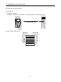
8.4 Connection with servo amplifier............................................................................................................... 8 - 4
8.4.1 Single axis ......................................................................................................................................... 8 - 4
8.4.2 Multidrop connection ......................................................................................................................... 8 - 5
4
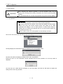
8.5 Display...................................................................................................................................................... 8 - 7
8.5.1 Outline of screen transition ............................................................................................................... 8 - 7
8.5.2 MR-PRU03 parameter unit setting ................................................................................................... 8 - 8
8.5.3 Monitor mode (status display)........................................................................................................... 8 - 9
8.5.4 Alarm/diagnostic mode .................................................................................................................... 8 -11
8.5.5 Parameter mode............................................................................................................................... 8 -13
8.5.6 Point table mode .............................................................................................................................. 8 -14
8.5.7 Test operation mode ........................................................................................................................ 8 -15
8.6 Error message list ................................................................................................................................... 8 -19
9. GENERAL GAIN ADJUSTMENT
9 - 1 to 9 -12
9.1 Different adjustment methods.................................................................................................................. 9 - 1
9.1.1 Adjustment on a single servo amplifier............................................................................................. 9 - 1
9.1.2 Adjustment using MR Configurator................................................................................................... 9 - 2
9.2 Auto tuning ............................................................................................................................................... 9 - 3
9.2.1 Auto tuning mode .............................................................................................................................. 9 - 3
9.2.2 Auto tuning mode operation.............................................................................................................. 9 - 4
9.2.3 Adjustment procedure by auto tuning............................................................................................... 9 - 5
9.2.4 Response level setting in auto tuning mode .................................................................................... 9 - 6
9.3 Manual mode 1 (simple manual adjustment) .......................................................................................... 9 - 7
9.4 Interpolation mode .................................................................................................................................. 9 -11
9.5 Differences between MELSERVO-J2-Super and MELSERVO-J3 in auto tuning................................ 9 -12
10. SPECIAL ADJUSTMENT FUNCTIONS
10- 1 to 10-16
10.1 Function block diagram......................................................................................................................... 10- 1
10.2 Adaptive filter ...................................................................................................................................... 10- 1
10.3 Machine resonance suppression filter.................................................................................................. 10- 4
10.4 Advanced vibration suppression control .............................................................................................. 10- 6
10.5 Low-pass filter ...................................................................................................................................... 10-10
10.6 Gain changing function ........................................................................................................................ 10-10
10.6.1 Applications ................................................................................................................................... 10-10
10.6.2 Function block diagram................................................................................................................. 10-11
10.6.3 Parameters .................................................................................................................................... 10-12
10.6.4 Gain changing operation............................................................................................................... 10-14
11. TROUBLESHOOTING
11- 1 to 11-14
11.1 Trouble at start-up................................................................................................................................. 11- 1
11.2 Operation at error occurrence .............................................................................................................. 11- 2
11.3 CC-Link communication error............................................................................................................... 11- 2
11.4 When alarm or warning has occurred .................................................................................................. 11- 3
11.4.1 Alarms and warning list.................................................................................................................. 11- 3
11.4.2 Remedies for alarms...................................................................................................................... 11- 4
11.4.3 Remedies for warnings ................................................................................................................. 11-11
11.5 Point table error.................................................................................................................................... 11-13
5
12. OUTLINE DRAWINGS
12- 1 to 12-12
12.1 Servo amplifier ...................................................................................................................................... 12- 1
12.2 Connector ............................................................................................................................................. 12-10
13. CHARACTERISTICS
13- 1 to 13-10
13.1 Overload protection characteristics ...................................................................................................... 13- 1
13.2 Power supply equipment capacity and generated loss ....................................................................... 13- 3
13.3 Dynamic brake characteristics.............................................................................................................. 13- 6
13.3.1 Dynamic brake operation............................................................................................................... 13- 6
13.3.2 The dynamic brake at the load inertia moment............................................................................. 13- 9
13.4 Cable flexing life................................................................................................................................... 13-10
13.5 Inrush currents at power-on of main circuit and control circuit ........................................................... 13-10
14. OPTIONS AND AUXILIARY EQUIPMENT
14- 1 to 14-90
14.1 Cable/connector sets ............................................................................................................................ 14- 1
14.1.1 Combinations of cable/connector sets .......................................................................................... 14- 2
14.1.2 Encoder cable/connector sets ....................................................................................................... 14- 8
14.1.3 Motor power supply cables ........................................................................................................... 14-17
14.1.4 Motor brake cables........................................................................................................................ 14-18
14.2 Regenerative options ........................................................................................................................... 14-19
14.3 FR-BU2-(H) brake unit ......................................................................................................................... 14-32
14.3.1 Selection ........................................................................................................................................ 14-33
14.3.2 Brake unit parameter setting......................................................................................................... 14-33
14.3.3 Connection example ..................................................................................................................... 14-34
14.3.4 Outline dimension drawings.......................................................................................................... 14-41
14.4 Power regeneration converter ............................................................................................................. 14-43
14.5 Power regeneration common converter.............................................................................................. 14-46
14.6 External dynamic brake ....................................................................................................................... 14-54
14.7 Battery MR-J3BAT ............................................................................................................................... 14-59
14.8 Heat sink outside mounting attachment (MR-J3ACN)........................................................................ 14-60
14.9 Selection example of wires .................................................................................................................. 14-62
14.10 No-fuse breakers, fuses, magnetic contactors ................................................................................. 14-68
14.11 Power factor improving DC reactor ................................................................................................... 14-69
14.12 Power factor improving reactors........................................................................................................ 14-71
14.13 Relays (recommended) ..................................................................................................................... 14-73
14.14 Surge absorbers (recommended) ..................................................................................................... 14-73
14.15 Noise reduction techniques ............................................................................................................... 14-74
14.16 Leakage current breaker.................................................................................................................... 14-81
14.17 EMC filter (recommended) ................................................................................................................ 14-83
14.18 MR-HDP01 manual pulse generator ................................................................................................. 14-88
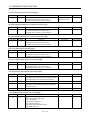
15. COMMUNICATION FUNCTION
15- 1 to 15-46
15.1 Configuration ......................................................................................................................................... 15- 1
15.2 Communication specifications .............................................................................................................. 15- 3
15.2.1 Communication overview............................................................................................................... 15- 3
15.2.2 Parameter setting........................................................................................................................... 15- 4
6
15.3 Protocol ................................................................................................................................................. 15- 5
15.3.1 Transmission data configuration.................................................................................................... 15- 5
15.3.2 Character codes ............................................................................................................................. 15- 6
15.3.3 Error codes ..................................................................................................................................... 15- 7
15.3.4 Checksum....................................................................................................................................... 15- 7
15.3.5 Time-out operation ......................................................................................................................... 15- 8
15.3.6 Retry operation............................................................................................................................... 15- 8
15.3.7 Initialization..................................................................................................................................... 15- 9
15.3.8 Communication procedure example.............................................................................................. 15- 9
15.4 Command and data No. list ................................................................................................................. 15-10
15.4.1 Read commands ........................................................................................................................... 15-10
15.4.2 Write commands ........................................................................................................................... 15-14
15.5 Detailed explanations of commands ................................................................................................... 15-17
15.5.1 Data processing ............................................................................................................................ 15-17
15.5.2 Status display ................................................................................................................................ 15-19
15.5.3 Parameters .................................................................................................................................... 15-20
15.5.4 External I/O signal statuses (DIO diagnosis) ............................................................................... 15-23
15.5.5 Device ON/OFF............................................................................................................................. 15-28
15.5.6 Disable/enable of I/O devices (DIO) ............................................................................................. 15-29
15.5.7 Input devices ON/OFF (test operation) ........................................................................................ 15-30
15.5.8 Test operation mode ..................................................................................................................... 15-31
15.5.9 Alarm history.................................................................................................................................. 15-37
15.5.10 Current alarm .............................................................................................................................. 15-38
15.5.11 Point table.................................................................................................................................... 15-39
15.5.12 Servo amplifier group designation .............................................................................................. 15-45
15.5.13 Other commands......................................................................................................................... 15-46
16. INDEXER POSITIONING OPERATION
16- 1 to 16-112
16.1 Function................................................................................................................................................. 16- 1
16.1.1 Overview......................................................................................................................................... 16- 1
16.1.2 Servo amplifier standard specifications (functions only)............................................................... 16- 1
16.1.3 Function list .................................................................................................................................... 16- 2
16.2 I/O signals (I/O devices) transferred to/from the programmable controller CPU................................ 16- 3
16.2.1 I/O signals (I/O devices)................................................................................................................. 16- 3
16.2.2 Detailed explanation of I/O signals ................................................................................................ 16- 5
16.2.3 Monitor codes................................................................................................................................ 16-14
16.2.4 Instruction codes (RWwn 2 RWwn 3) ................................................................................... 16-15
16.2.5 Respond codes (RWrn 2) .......................................................................................................... 16-22
16.3 Signal.................................................................................................................................................... 16-23
16.3.1 Signal (device) explanation........................................................................................................... 16-23
16.3.2 Detailed description of signals (devices) ...................................................................................... 16-26
16.4 Switching power on for the first time ................................................................................................... 16-29
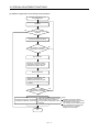
16.4.1 Startup procedure ......................................................................................................................... 16-29
16.4.2 Wiring check .................................................................................................................................. 16-30
16.4.3 Surrounding environment ............................................................................................................. 16-31
16.5 Startup .................................................................................................................................................. 16-32
16.5.1 Power on and off procedures........................................................................................................ 16-32
16.5.2 Stop................................................................................................................................................ 16-32
7
16.5.3 Test operation ............................................................................................................................... 16-33
16.5.4 Parameter setting.......................................................................................................................... 16-34
16.5.5 Point table setting.......................................................................................................................... 16-35
16.5.6 Actual operation ............................................................................................................................ 16-35
16.6 Servo amplifier display......................................................................................................................... 16-36
16.7 Automatic operation mode................................................................................................................... 16-38
16.7.1 What is automatic operation mode?............................................................................................. 16-38
16.7.2 Automatic operation mode 1 (Rotation direction specifying indexer).......................................... 16-39
16.7.3 Automatic operation mode 2 (Shortest rotating indexer) ............................................................. 16-49
16.8 Manual operation mode ....................................................................................................................... 16-58
16.8.1 Indexer JOG operation.................................................................................................................. 16-58
16.8.2 JOG operation ............................................................................................................................... 16-60
16.9 Home position return mode ................................................................................................................. 16-61
16.9.1 Outline of home position return..................................................................................................... 16-61
16.9.2 Torque limit changing dog type home position return.................................................................. 16-63
16.9.3 Torque limit changing data setting type home position return..................................................... 16-65
16.9.4 Home position return automatic return function ........................................................................... 16-66
16.10 Absolute position detection system ................................................................................................... 16-67
16.11 Parameters......................................................................................................................................... 16-70
16.11.1 Basic setting parameters (No.PA
)....................................................................................... 16-70
)............................................................................................ 16-79
16.11.2 Gain/filter parameters (No.PB
16.11.3 Extension setting parameters (No.PC
) ............................................................................... 16-87
16.11.4 I/O setting parameters (No.PD
)....................................................................................... 16-93
16.12 TROUBLESHOOTING ...................................................................................................................... 16-98
16.12.1 Trouble at start-up....................................................................................................................... 16-98
16.12.2 Operation at error occurrence..................................................................................................... 16-99
16.12.3 CC-Link communication error..................................................................................................... 16-99
16.12.4 When alarm or warning has occurred ...................................................................................... 16-100
16.12.5 Point table error......................................................................................................................... 16-112
APPENDIX
App.- 1 to App.-30
App. 1 Parameter list..................................................................................................................................App.- 1
App. 2 Signal layout recording paper ........................................................................................................App.- 3
App. 3 Twin type connector: outline drawing for 721-2105/026-000(WAGO) .........................................App.- 4
App. 4 Change of connector sets to the RoHS compatible products.......................................................App.- 5
App. 5 MR-J3-200T-RT servo amplifier.....................................................................................................App.- 6
App. 6 Selection example of servo motor power cable ...........................................................................App.-10
App. 7 Parameter list.................................................................................................................................App.-11
App. 8 Program example with MELSEC-A series programmable controllers
(point table positioning operation).................App.-13
8
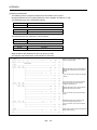
1. FUNCTIONS AND CONFIGURATION
1. FUNCTIONS AND CONFIGURATION
1.1 Introduction
The MR-J3- T CC-Link compatible servo amplifier can support the CC-Link communication functions. Up to 42
axes of servo amplifiers can be controlled/monitored from the programmable controller side.
As the servo, it has the function to perform positioning operation by merely setting the position data (target
positions), servo motor speeds, acceleration and deceleration time constants, etc. to point tables as if setting
them in parameters. The servo amplifier is the most appropriate to configure a program-free, simple positioning
system or to simplify a system, for example.
There are 31 points of point tables to be used when 1 station is occupied and 255 points when 2 stations are
occupied.
All servo motors are equipped with an absolute position encoder as standard. An absolute position detection
system can be configured by merely adding a battery to the servo amplifier. Once the home position has been
set, home position return is not required at power on, alarm occurrence, etc.
The MR-J3-T is made easier to use and higher in function by using it with the MR Configurator.
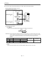
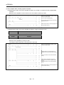
1.1.1 Features of CC-Link communication functions
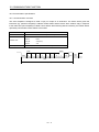
(1) Fast communication
Fast communication can be made by cyclic transmission of not only bit data but also word data.
(a) The highest communication speed is 10Mbps.
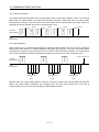
(b) The broadcast polling system ensures as high as 3.9ms to 6.7ms even at the maximum link scan
(10Mbps).
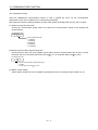
(2) Variable communication speed/distance system
Selection of speed/distance allows use in a wide range of areas from a system requiring high speed to a
system requiring long distance.
(3) System fault prevention (station separating function)
Because of connection in the bus system, any remote or local station that has become faulty due to poweroff or the like does not affect communications with normal remote and local stations.
In addition, use of the two-piece terminal block allows the unit to be changed during data link.
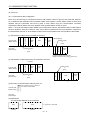
(4) Factory Automation compatible
As the remote device stations of CC-Link, the servo amplifiers share a link system and can be
controlled/monitored with programmable controller user programs.
From the programmable controller side, the running speed, acceleration/deceleration time constant and
other settings of servo motors can be changed/checked and the servo motors started and stopped.
1- 1
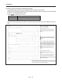
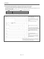
1. FUNCTIONS AND CONFIGURATION
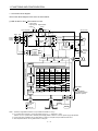
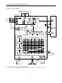
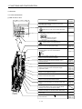
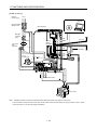
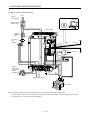
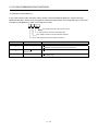
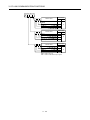
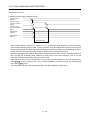
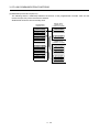
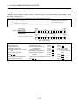
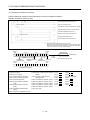
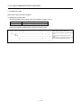
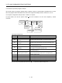
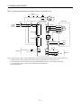
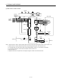
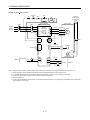
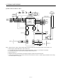
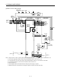
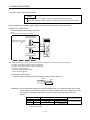
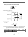
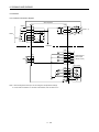
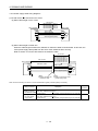
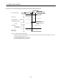
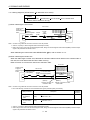
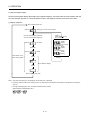
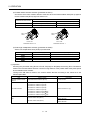
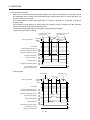
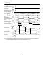
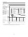
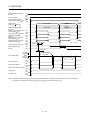
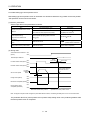
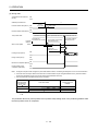
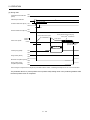
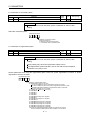
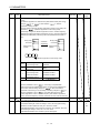
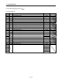
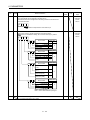
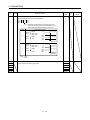
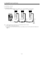
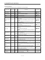
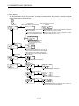
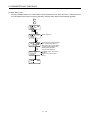
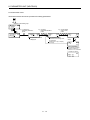
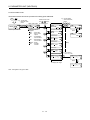
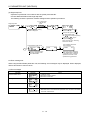
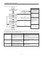
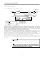
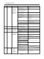
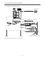
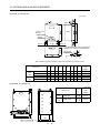
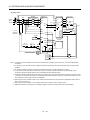
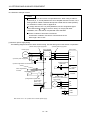
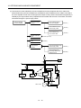
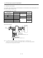
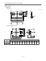
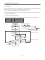
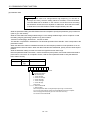
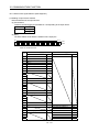
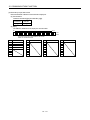
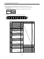
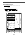
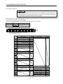
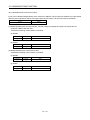
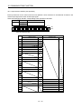
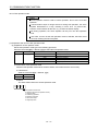
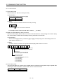
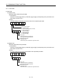
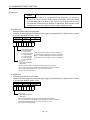
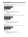
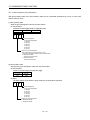
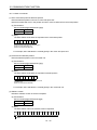
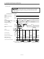
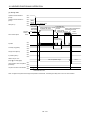
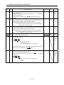
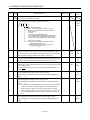
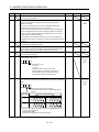
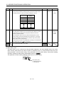
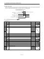
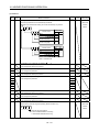
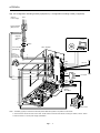
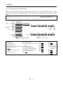
1.1.2 Function block diagram
The function block diagram of this servo is shown below.
(1) MR-J3-350T or less MR-J3-200T4 or less
Power factor
improving DC Regenerative
reactor
option
Servo amplifier P1
(Note 2)
Power
supply
MC
D N( )
Diode
stack Relay
Servo motor
(Note 1)
L1
L2
CHARGE
lamp
L3
Current
detector
Regenerative
TR
V
V
W
W
24VDC
Electromagnetic
brake
B1
B2
Base
amplifier
Voltage
detection
Current
detection
Overcurrent
protection
M
RA
Control
circuit
power
supply
L21
U
Dynamic
brake
(Note 4) Cooling fan
L11
U
CN2
NFB
P( ) C
P2
Encoder
Current
control
Speed
control
Position
control
(Note 3)
Position
command
creation
CN6
1
1000
1000
80
80
0
0
2
2000
2000
100
100
0
0
3
4000
2000
70
60
500
1
1
4
500
2000
60
70
1000
5
1000
2000
80
80
0
0
6
2000
1000
80
80
0
0
7
1000
1000
80
80
0
0
8
1000
1000
100
100
0
0
1000
1000
100
100
0
0
255 2000
2000
80
80
0
0
CN1
DI/O Control
Servo on
Start
Failure, etc
Personal
computer
USB
CC-Link
MR-J3BAT
CN4
Model adaptive control
Point table
Acceleration Deceleration
No. Position
Speed time
Dwell Auxiliary
time
data
constant
constant
USB
RS-422
CN5
CN3
Optional battery
(for absolute position
detection system)
Controller
RS-422
Note 1. The built-in regenerative resistor is not provided for the MR-J3-10T (1).
2. For 1-phase 200 to 230VAC, connect the power supply to L1, L2 and leave L3 open.
There is no L3 for 1-phase 100 to 120VAC power supply. Refer to section 1.2 for the power supply specification.
3. For the case when 2 stations are occupied. When 1 station is occupied, the point table ends at No.31.
4. Servo amplifiers MR-J3-70T or greater have a cooling fan.
1- 2
1. FUNCTIONS AND CONFIGURATION
(2) MR-J3-350T4 MR-J3-500T(4) MR-J3-700T(4)
Power factor
improving DC Regenerative
reactor
option
Servo amplifier P1
(Note 1)
Power
supply
MC
Servo motor
Diode
stack Relay
L1
L2
CHARGE
lamp
L3
Current
detector
Regenerative
TR
V
V
W
W
24VDC
Electromagnetic
brake
B1
B2
Base
amplifier
Voltage
detection
Current
detection
Overcurrent
protection
M
RA
Control
circuit
power
supply
L21
U
Dynamic
brake
Cooling fan
L11
U
CN2
NFB
C N
P
P2
Encoder
Current
control
Speed
control
Position
control
(Note 2)
Position
command
creation
CN6
1
1000
1000
80
80
0
0
2
2000
2000
100
3
4000
2000
70
100
0
0
60
500
4
500
2000
1
60
70
1000
5
1000
1
2000
80
80
0
6
0
2000
1000
80
80
0
0
7
1000
1000
80
80
0
0
8
1000
1000
100
100
0
0
1000
1000
100
100
0
0
255 2000
2000
80
80
0
0
CN1
DI/O Control
Servo on
Start
Failure, etc
Personal
computer
USB
CC-Link
MR-J3BAT
CN4
Model adaptive control
Point table
Acceleration Deceleration
No. Position
Speed time
Dwell Auxiliary
time
data
constant
constant
USB
RS-422
CN5
CN3
Controller
RS-422
Note 1. Refer to section 1.2 for the power supply specification.
2. For the case when 2 stations are occupied. When 1 station is occupied, the point table ends at No.31.
1- 3
Optional battery
(for absolute position
detection system)
1. FUNCTIONS AND CONFIGURATION
(3) MR-J3-11KT(4) to 22KT(4)
Power factor
improving DC Regenerative
reactor
option
Servo amplifier
NFB
(Note 1)
Power
supply
MC
C N
P
P1
Servo motor
Diode Thyristor
stack
L1
L2
CHARGE
lamp
L3
Current
detector
Regenerative
TR
U
U
V
V
W
W
M
Cooling fan
RA
L11
Control
circuit
power
supply
Electromagnetic
brake
B1
B2
Base
amplifier
Voltage
detection
Current
detection
Overcurrent
protection
CN2
L21
24VDC
Encoder
Current
control
Speed
control
Position
control
(Note 2)
Position
command
creation
CN6
1
1000
1000
80
80
0
0
2
2000
2000
100
3
4000
2000
70
100
0
0
60
500
4
500
2000
1
60
70
1000
5
1000
1
2000
80
80
0
6
0
2000
1000
80
80
0
0
7
1000
1000
80
80
0
0
8
1000
1000
100
100
0
0
1000
1000
100
100
0
0
255 2000
2000
80
80
0
0
CN1
DI/O Control
Servo on
Start
Failure, etc
Personal
computer
USB
CC-Link
MR-J3BAT
CN4
Model adaptive control
Point table
Acceleration Deceleration
No. Position
Speed time
Dwell Auxiliary
time
data
constant
constant
USB
RS-422
CN5
CN3
Controller
RS-422
Note 1. Refer to section 1.2 for the power supply specification.
2. For the case when 2 stations are occupied. When 1 station is occupied, the point table ends at No.31.
1- 4
Optional battery
(for absolute position
detection system)
1. FUNCTIONS AND CONFIGURATION
1.1.3 System configuration
This section provides operations using this servo.
Use of CC-Link enables you to freely configure any system from a single-axis system to an up to 42-axis
system.
Set the following values to the point table.
Name
Setting range
Unit
0.001[mm]
Position data
0.01[mm]
999999 to 999999
0.1[mm]
1[mm]
Servo motor speed
0 to max. speed
[r/min]
Acceleration time constant
0 to 20000
[ms]
Deceleration time constant
0 to 20000
[ms]
Dwell
0 to 20000
[ms]
0 to 3
Auxiliary function
(Refer to section 4.2)
There are 31 points of point tables to be used when 1 station is occupied and 255 points when 2 stations are
occupied.
(1) Operation using CC-Link communication functions
(a) Operation
All devices can be controlled by CC-Link communication. Also, each point table setting, point table
selection, parameter value change, setting, monitor, servo motor operation and others can be
performed.
(b) Configuration
Programmable controller
CC-Link master unit
To the next axis
Servo amplifier
(Axis 1)
Servo amplifier
(Axis 2)
CN1
CN1
CN6
CNP3
CN6
CNP3
CN2
CN2
1- 5
1. FUNCTIONS AND CONFIGURATION
(2) Operation using CC-Link communication functions and external input signals
(a) Operation
Using parameter No.PD06 to PD08 and parameter No.PD12, PD14, input devices can be assigned to
the external input devices of CN1A and CN1B. The signals assigned to the external input signals cannot
be used with the CC-Link communication functions. Output devices can be used with the CN6
connectors and CC-Link communication functions simultaneously.
(b) Configuration
Programmable controller
CC-Link master unit
To the next axis
Servo amplifier
(Axis 1)
Servo amplifier
(Axis 2)
CN1
CN1
CN6
CNP3
CN6
CNP3
CN2
CN2
External I/O
signal
1- 6
External I/O
signal
1. FUNCTIONS AND CONFIGURATION
1.2 Servo amplifier standard specifications
(1) 200V class, 100V class
Servo amplifier
10T 20T 40T 60T 70T 100T 200T 350T 500T 700T 11KT 15KT 22KT 10T1 20T1 40T1
MR-J3Item
Power supply
Voltage/frequency
Permissible voltage fluctuation
Permissible frequency
fluctuation
Power supply capacity
Inrush current
Voltage,
frequency
Permissible
voltage fluctuation
Control circuit
Permissible
power supply
frequency
fluctuation
Input
Inrush current
Voltage
Interface power
Power supply
supply
capacity
Control System
Dynamic brake
Operation mode
Command system
Protective functions
3-phase or 1-phase 200 to
230VAC, 50/60Hz
3-phase or 1-phase 200 to
230VAC: 170 to 253VAC
3-phase 200 to 230VAC, 50/60Hz
3-phase 170 to 253VAC
1-phase 100V to
120VAC, 50/60Hz
1-phase 85 to
132VAC
Within 5%
Refer to section 13.2
Refer to section 13.5
1-phase 100 to
120VAC, 50/60Hz
1-phase 85 to
132VAC
1-phase 200 to 230VAC, 50/60Hz
1-phase 170 to 253VAC
Within 5%
30W
45W
30W
Refer to section 13.5
24VDC 10%
(Note 1) 150mA
Sine-wave PWM control, current control system
Built-in
External option
Built-in
Overcurrent shut-off, regenerative overvoltage shut-off, overload shut-off (electronic thermal relay),
servo motor overheat protection, encoder error protection, regenerative brake error protection,
undervoltage, instantaneous power failure protection, overspeed protection, excessive error
protection
Positioning by specifying the point table No. (255 points)
Operational
specifications
Position command Set in point table. 1-point feed length setting range: 1[ m] to 999.999[mm]
Point table
input
number
Speed command Set in point table. Acceleration/deceleration time is set in point table.
input
input
S-pattern acceleration/deceleration time constant is set in parameter No.PC13.
Signed absolute value command system, incremental value command system, signed absolute
System
value command/incremental value command specifying system
Operational
Remote register setting is used for positioning.
specifications
Position
Position command Remote register is used to set position command data.
command
input
Feed length input setting range: 1 m to 999.999m
data input
Remote register is used to make selection from point table.
(when 2
Speed command
Remote register is used to set speed command data (speed).
stations are input
S-pattern acceleration/deceleration time constant is set in parameter No.PC13.
occupied)
Signed absolute value command system, incremental value command system, signed absolute
System
value command/incremental value command specifying system
Point table number input, position data input system
Point table
Positioning operation is performed once in accordance with the position and speed commands.
Automatic
operation
Automatic
Varied speed operation (2 to 255 speeds), automatic continuous positioning operation (2 to 255
mode
continuous
points)
operation
Jog operation is performed in accordance with the parameter-set speed command by contact input
Manual
Jog
or through CC-Link communication function.
operation
Manual pulse
Manual feed is made by manual pulse generator.
mode
generator
Command pulse multiplication: 1, 10 or 100 is selected using parameter.
1- 7
1. FUNCTIONS AND CONFIGURATION
Servo amplifier
MR-J310T 20T 40T 60T 70T 100T 200T 350T 500T 700T 11KT 15KT 22KT 10T1 20T1 40T1
Item
Dog type
Home position return is made starting with Z-phase pulse after passage of proximity dog.
Home position address may be set. Home position shift distance may be set. Home position return
direction may be selected.
Automatic at-dog home position return return/automatic stroke return function.
Count type
Home position return is made by counting encoder pulses after contact with proximity dog.
Home position address may be set. Home position shift value may be set. Home position return
direction may be set.
Automatic at-dog home position return return/automatic stroke return function.
Data setting type
Home position return is made without dog.
Home position may be set at any position by manual operation, etc. Home position address may be
set.
Stopper type
Home position return is made by pressing machine part against stroke end.
Home position address may be set. Home position return direction may be set.
Operation mode
Position where servo-on (RYn0) is switched on is defined as home position.
Home position
Home position address may be set.
ignorance
(Servo-on position
as home position)
Home
position
return
mode
Dog type rear end
reference
Home position return is made with respect to the rear end of a proximity dog.
Home position address may be set. Home position shift value may be set. Home position return
direction may be set.
Automatic at-dog home position return return/automatic stroke return function.
Count type front
end reference
Home position return is made with respect to the front end of a proximity dog.
Home position address may be set. Home position shift value may be set. Home position return
direction may be set.
Automatic at-dog home position return return/automatic stroke return function.
Dog cradle type
Home position return is made with respect to the front end of a proximity dog by the first Z-phase
pulse.
Home position address may be set. Home position shift value may be set. Home position return
direction may be set.
Automatic at-dog home position return return/automatic stroke return function.
Home position return is made with respect to the front end of a proximity dog by the last Z-phase
pulse.
Dog type last
Home position address may be set. Home position shift value may be set. Home position return
Z-phase reference
direction may be set.
Automatic at-dog home position return return/automatic stroke return function.
Home position return is made to the dog front end with respect to the front end of a proximity dog.
Dog type front end Home position address may be set. Home position shift value may be set. Home position return
direction may be set.
reference
Automatic at-dog home position return return/automatic stroke return function.
Home position return is made with respect to the first Z-phase to the Z-phase.
Dogless
Home position address may be set. Home position shift value may be set. Home position return
Z-phase reference
direction may be set.
Automatic positioning to home
position
Other functions
Structure
High-speed automatic return to a defined home position.
Absolute position detection, backlash function
Overtravel prevention using external limit switch
Software stroke limit
Self-cooled, open
(IP00)
Force-cooling, open (IP00)
1- 8
Self-cooled, open
(IP00)
1. FUNCTIONS AND CONFIGURATION
Servo amplifier
MR-J310T 20T 40T 60T 70T 100T 200T 350T 500T 700T 11KT 15KT 22KT 10T1 20T1 40T1
Item
Environment
Ambient
temperature
Ambient
humidity
In operation
In storage
[ ]
(Note 2) 0 to 55 (non-freezing)
[ ]
(Note 2) 32 to 131 (non-freezing)
[ ]
20 to 65 (non-freezing)
[ ]
4 to 149 (non-freezing)
In operation
90%RH or less (non-condensing)
In storage
Ambient
Indoors (no direct sunlight)
Free from corrosive gas, flammable gas, oil mist, dust and dirt
Altitude
Max. 1000m above sea level
Vibration
5.9 [m/s2] or less
Mass
[kg]
0.8
0.8
0.8
1.0
[lb]
1.76 1.76 2.21 2.21 3.09 3.09 4.63 5.07 10.1 13.7 39.7 39.7 41.9 1.76
0.8
1.0
1.0
1.4
1.4
2.1
2.3
4.6
6.2
18
18
19
1.76
2.21
Note 1. 150mA is the value applicable when all I/O signals are used. The current capacity can be decreased by reducing the number of
I/O points.
2. When closely mounting the servo amplifier of 3.5kW or less, operate them at the ambient temperatures of 0 to 45 (32 to
113 ) or at 75% or smaller effective load ratio.
1- 9
1. FUNCTIONS AND CONFIGURATION
(2) 400V class
Servo amplifier
MR-J3-
60T4
100T4
200T4
350T4
500T4
700T4
11KT4
15KT4
22KT4
Item
3-phase 380 to 480VAC, 50/60Hz
3-phase 323 to 528VAC
Power supply
Voltage/frequency
Permissible voltage fluctuation
Permissible frequency
fluctuation
Power supply capacity
Inrush current
Voltage,
frequency
Permissible
voltage fluctuation
Control circuit
Permissible
power supply
frequency
fluctuation
Input
Inrush current
Voltage
Interface power
Power supply
supply
capacity
Control System
Dynamic brake
Operation mode
Command system
Protective functions
Within 5%
Refer to section 13.2
Refer to section 13.5
1-phase 380 to 480VAC, 50/60Hz
1-phase 323 to 528VAC
Within 5%
30W
45W
Refer to section 13.5
24VDC 10%
(Note) 150mA
Sine-wave PWM control, current control system
Built-in
External option
Overcurrent shut-off, regenerative overvoltage shut-off, overload shut-off (electronic thermal relay),
servo motor overheat protection, encoder error protection, regenerative brake error protection,
undervoltage, instantaneous power failure protection, overspeed protection, excessive error
protection
Positioning by specifying the point table No. (255 points)
Operational
specifications
Position command Set in point table. 1-point feed length setting range: 1[ m] to 999.999[mm]
Point table
input
number
Speed command Set in point table. Acceleration/deceleration time is set in point table.
input
input
S-pattern acceleration/deceleration time constant is set in parameter No.PC13.
Signed absolute value command system, incremental value command system, signed absolute
System
value command/incremental value command specifying system
Operational
Remote register setting is used for positioning.
specifications
Position
Position command Remote register is used to set position command data.
command
input
Feed length input setting range: 1 m to 999.999m
data input
Remote register is used to make selection from point table.
(when 2
Speed command
Remote register is used to set speed command data (speed).
stations are input
S-pattern acceleration/deceleration time constant is set in parameter No.PC13.
occupied)
Signed absolute value command system, incremental value command system, signed absolute
System
value command/incremental value command specifying system
Point table number input, position data input system
Point table
Positioning operation is performed once in accordance with the position and speed commands.
Automatic
operation
Automatic
Varied speed operation (2 to 255 speeds), automatic continuous positioning operation (2 to 255
mode
continuous
points)
operation
Jog operation is performed in accordance with the parameter-set speed command by contact input
Manual
Jog
or through CC-Link communication function.
operation
Manual pulse
Manual feed is made by manual pulse generator.
mode
generator
Command pulse multiplication: 1, 10 or 100 is selected using parameter.
1 - 10
1. FUNCTIONS AND CONFIGURATION
Servo amplifier
MR-J3-
60T4
100T4
200T4
350T4
500T4
700T4
11KT4
15KT4
22KT4
Item
Dog type
Count type
Data setting type
Stopper type
Home position
ignorance
(Servo-on position
as home position)
Home position return is made starting with Z-phase pulse after passage of proximity dog.
Home position address may be set. Home position shift distance may be set. Home position return
direction may be selected.
Automatic at-dog home position return return/automatic stroke return function.
Home position return is made by counting encoder pulses after contact with proximity dog.
Home position address may be set. Home position shift value may be set. Home position return
direction may be set.
Automatic at-dog home position return return/automatic stroke return function.
Home position return is made without dog.
Home position may be set at any position by manual operation, etc. Home position address may be
set.
Home position return is made by pressing machine part against stroke end.
Home position address may be set. Home position return direction may be set.
Position where servo-on (RYn0) is switched on is defined as home position.
Home position address may be set.
Operation mode
Home position return is made with respect to the rear end of a proximity dog.
Home position address may be set. Home position shift value may be set. Home position return
Home
direction may be set.
position
Automatic at-dog home position return return/automatic stroke return function.
return
Home position return is made with respect to the front end of a proximity dog.
mode
Home position address may be set. Home position shift value may be set. Home position return
Count type front
direction may be set.
end reference
Automatic at-dog home position return return/automatic stroke return function.
Home position return is made with respect to the front end of a proximity dog by the first Z-phase
pulse.
Dog cradle type
Home position address may be set. Home position shift value may be set. Home position return
direction may be set.
Automatic at-dog home position return return/automatic stroke return function.
Home position return is made with respect to the front end of a proximity dog by the last Z-phase
pulse.
Dog type last
Home position address may be set. Home position shift value may be set. Home position return
Z-phase reference
direction may be set.
Automatic at-dog home position return return/automatic stroke return function.
Home position return is made to the dog front end with respect to the front end of a proximity dog.
Dog type front end Home position address may be set. Home position shift value may be set. Home position return
direction may be set.
reference
Automatic at-dog home position return return/automatic stroke return function.
Home position return is made with respect to the first Z-phase to the Z-phase.
Dogless
Home position address may be set. Home position shift value may be set. Home position return
Z-phase reference
direction may be set.
Automatic positioning to home
High-speed automatic return to a defined home position.
position
Absolute position detection, backlash function
Other functions
Overtravel prevention using external limit switch
Software stroke limit
Self-cooled, open
Force-cooling, open (IP00)
Structure
(IP00)
Dog type rear end
reference
1 - 11
1. FUNCTIONS AND CONFIGURATION
Servo amplifier
MR-J3-
60T4
100T4
200T4
350T4
500T4
700T4
11KT4
15KT4
22KT4
Item
Environment
Ambient
temperature
Ambient
humidity
In operation
In storage
In operation
In storage
[
[
[
[
]
]
]
]
0 to 55 (non-freezing)
32 to 131 (non-freezing)
20 to 65 (non-freezing)
4 to 149 (non-freezing)
90%RH or less (non-condensing)
Indoors (no direct sunlight)
Free from corrosive gas, flammable gas, oil mist, dust and dirt
Altitude
Max. 1000m above sea level
Vibration
5.9 [m/s2] or less
[kg]
1.7
1.7
2.1
4.6
4.6
6.2
18
18
19
Mass
[lb]
3.75
3.75
4.63
10.1
10.1
13.7
39.7
39.7
41.9
Note. 150mA is the value applicable when all I/O signals are used. The current capacity can be decreased by reducing the number of
I/O points.
Ambient
1 - 12
1. FUNCTIONS AND CONFIGURATION
1.3 Function list
The following table lists the functions of this servo. For details of the functions, refer to the reference field.
Function
Positioning by automatic
operation
Varied speed operation
Automatic continuous positioning
operation
Home position return
High-resolution encoder
Absolute position detection
system
Gain changing function
Advanced vibration suppression
control
Adaptive filter
Low-pass filter
Machine analyzer function
Machine simulation
Gain search function
Slight vibration suppression
control
Electronic gear
Auto tuning
S-pattern
acceleration/deceleration time
constant
Regenerative option
Brake unit
Regeneration converter
Alarm history clear
Description
Select the required ones from among 31 preset point tables and perform
operation in accordance with the set values.
Use the external input signal or communication function to choose the point
tables.
Servo motor speed can be varied continuously until the preset moving
distance is reached. (Max. set speeds: 255 speeds)
By merely choosing one point table and starting operation, positioning can
be executed continuously in accordance with several point tables.
Dog type, count type, data setting type, stopper type, home position
ignorance, dog type rear end reference, count type front end reference, dog
cradle type
High-resolution encoder of 262144 pulses/rev is used as a servo motor
encoder.
By merely setting the home position once, home position return need not be
done at each power on.
You can switch between gains during rotation and gains during stop or use
an input device to change gains during operation.
This function suppresses vibration at the arm end or residual vibration.
Servo amplifier detects mechanical resonance and sets filter characteristics
automatically to suppress mechanical vibration.
Suppresses high-frequency resonance which occurs as servo system
response is increased.
Analyzes the frequency characteristic of the mechanical system by simply
connecting a MR Configurator installed personal computer and servo
amplifier.
MR Configurator is necessary for this function.
Can simulate machine motions on a personal computer screen on the basis
of the machine analyzer results.
MR Configurator is necessary for this function.
Personal computer changes gains automatically and searches for
overshoot-free gains in a short time.
MR Configurator is necessary for this function.
Suppresses vibration of 1 pulse produced at a servo motor stop.
The electronic gear is used to make adjustment so that the servo amplifier
setting matches the machine moving distance. Also, changing the electronic
gear value allows the machine to be moved at any multiplication ratio to the
moving distance using the servo amplifier.
Automatically adjusts the gain to optimum value if load applied to the servo
motor shaft varies.
Acceleration/deceleration can be made smoothly.
Used when the built-in regenerative resistor of the servo amplifier does not
have sufficient regenerative capability for the regenerative power generated.
Used when the regenerative option cannot provide enough regenerative
power.
Can be used with the servo amplifier of 5kW or more.
Used when the regenerative option cannot provide enough regenerative
power.
Can be used with the servo amplifier of 5kW or more.
Alarm history is cleared.
1 - 13
Reference
Section 5.4
Section 5.4.2
(4)(b)
Section 5.4.2 (4)
Section 5.6
Section 5.7
Section 10.6
Section 10.4
Section 10.2
Section 10.5
Parameters No.
PB24
Parameter No.
PA06, PA07
Section 9.2
Parameters No.
PC13
Section 14.2
Section 14.3
Section 14.4
Parameter No.
PC18
1. FUNCTIONS AND CONFIGURATION
Function
I/O signal selection (Device
setting)
Torque limit
Output signal (DO) forced output
Test operation mode
Limit switch
Software limit
Description
Reference
Any input device such as servo-on (SON) can be assigned to any pin of CN6 Parameter No.
connector.
PD06 to PD08
PD12 PD14
Servo motor-torque is limited.
Section 4.6.3
Section 6.1.11
Output signal can be forced on/off independently of the servo status.
Section 7.7.4
Use this function for output signal wiring check, etc.
Section 8.5.7(4)
JOG operation positioning operation DO forced output single - step
Section 7.7
feed.
Section 8.5.7
MR Configurator is necessary for this function.
The servo motor travel region can be limited using the forward rotation
stroke end (LSP)/reverse rotation stroke end (LSN).
The travel region is limited using parameters in terms of address.
Section 6.3.6
The function similar to that of a limit switch is limited by parameter.
1 - 14
1. FUNCTIONS AND CONFIGURATION
1.4 Model code definition
(1) Rating plate
MITSUBISHI
MODELMR-J3-10T
AC SERVO
Model
Capacity
POWER : 100W
INPUT : 0.9A 3PH+1PH200-230V 50Hz
3PH+1PH200-230V 60Hz
1.3A 1PH 200-230V 50/60Hz
OUTPUT : 170V 0-360Hz 1.1A
SERIAL : A34230001
Applicable power supply
Rated output current
Serial number
PASSED
MITSUBISHI ELECTRIC CORPORATION
MADE IN JAPAN
(2) Model
MR-J3-100T(4) or less
MR-J3-200T(4)
With no regenerative resistor
Series
Symbol
Description
-PX
Indicates a servo
amplifier of 11k to 22kW
that does not use a
regenerative resistor as
standard accessory.
Power supply
Symbol
(Note 1)
None
(Note 2)
1
4
Description
3-phase or 1-phase 200
to 230VAC
Rating plate
Rating plate
1-phase 100 to 120VAC
3-phase 380 to 480VAC
MR-J3-350T
MR-J3-350T4 500T(4)
Note 1. 1-phase 200V to 230V is
supported by 750W or less.
2. 1-phase 100V to 120V is
supported by 400W or less.
Built-in positioning function
Rated output
Symbol Rated
output [kW]
10
0.1
20
0.2
40
0.4
60
0.6
70
0.75
100
1
200
2
350
3.5
500
5
700
7
11K
11
15K
15
22K
22
Rating plate
Rating plate
MR-J3-700T(4)
Rating plate
1 - 15
MR-J3-11KT(4) to 22KT(4)
Rating plate
1. FUNCTIONS AND CONFIGURATION
1.5 Combination with servo motor
The following table lists combinations of servo amplifiers and servo motors. The same combinations apply to
the servo motors with an electromagnetic brakes and the servo motors with a reduction gear.
Servo motors
Servo amplifier
MR-J3-10T (1)
HF-MP
HF-KP
053
053
13
1000r/min
2000r/min
51
52
23
23
MR-J3-40T (1)
43
43
73
73
MR-J3-60T
81
MR-J3-200T
121
201
202
301
352
MR-J3-500T
421
502
MR-J3-700T
702
MR-J3-11KT
MR-J3-15KT
MR-J3-22KT
Servo motors
HA-LP
1000r/min
1500r/min
2000r/min
601
701M
702
MR-J3-500T
MR-J3-11KT
MR-J3-15KT
502
MR-J3-22KT
801
12K1
15K1
20K1
25K1
11K1M
11K2
15K1M
15K2
22K1M
22K2
Servo motors
Servo amplifier
HF-SP
MR-J3-60T4
524
MR-J3-100T4
1024
MR-J3-200T4
MR-J3-350T4
1524
1500r/min
2000r/min
2024
5024
MR-J3-700T4
7024
MR-J3-11KT4
HA-LP
1000r/min
3524
MR-J3-500T4
6014
8014
HC-LP
52
102
152
MR-J3-350T
MR-J3-700T
HC-UP
72
MR-J3-100T
Servo amplifier
HC-RP
13
MR-J3-20T (1)
MR-J3-70T
HF-SP
12K14
701M4
11K1M4
11K24
MR-J3-15KT4
15K14
15K1M4
15K24
MR-J3-22KT4
20K14
22K1M4
22K24
1 - 16
102
103
153
203
353
503
152
152
202
202
352
502
302
1. FUNCTIONS AND CONFIGURATION
1.6 Structure
1.6.1 Parts identification
(1) MR-J3-100T or less
Name/Application
Display
The 3-digit, seven-segment LED shows the servo
status and alarm number.
2 3
0 1
2 3
5 6
2 3
9
5 6
7 8
9
0 1
7 8
2 3
4
0 1
4
MODE
Select the CC-Link communication baud rate.
7 8
5 6
Baud rate switch (MODE)
5 6
7 8
4
Section 5.3
Chapter 11
Section 3.2.4
9
4
Detailed
explanation
Station number switches (STATION NO.)
Set the station number of the servo amplifier.
9
0 1
X10 STATION NO. X1
5 6
Section 3.2.3
7 8
2 3
4
7 8
2 3
5 6
9
4
Set the one place.
Set the ten place.
0 1
9
0 1
Occupied station count switch (SW1)
SW1
Set the number of occupied stations.
Main circuit power supply connector (CNP1)
Used to connect the input power supply.
Communication alarm display section
Indicates alarms in CC-Link communication.
L.RUN
SD
RD
L.ERR
Section 3.2.5
Section 4.1
Section 4.3
Section 12.1
Section 11.3
USB communication connector (CN5)
Used to connect the personal computer.
Chapter 7
RS-422 communication connector (CN3)
Used to connect the MR-PRU03 parameter unit or
personal computer.
Chapter 7
Chapter 8
Chapter 15
CC-Link connector (CN1)
Wire the CC-Link cable.
Section 3.2.2
Control circuit connector (CNP2)
Used to connect the control circuit power supply/
regenerative option.
Section 4.1
Section 4.3
Section 12.1
Section 14.2
I/O signal connector (CN6)
Used to connect digital I/O signals.
Section 4.2
Section 4.4
Servo motor power connector (CNP3)
Used to connect the servo motor.
Section 4.1
Section 4.3
Section 12.1
Encoder connector (CN2)
Used to connect the servo motor encoder.
Section 4.10
Section 14.1
Battery connector (CN4)
Used to connect the battery for absolute position data
backup.
Section 5.8
Section 14.7
Charge lamp
Lit to indicate that the main circuit is charged. While
this lamp is lit, do not reconnect the cables.
Fixed part
(2 places)
Battery holder
Contains the battery for absolute position data backup.
Section 5.8
Rating plate
Section 1.4
Protective earth (PE) terminal (
Ground terminal.
1 - 17
)
Section 4.1
Section 4.3
Section 12.1
1. FUNCTIONS AND CONFIGURATION
(2) MR-J3-200T(4) or less
Name/Application
Display
The 3-digit, seven-segment LED shows the servo
status and alarm number.
0
4
Select the CC-Link communication baud rate.
2 3
7 8
0 1
7 8
2 3
5 6
Section 3.2.4
9
2 3
7 8
MODE
5
0
7 8
2 3
Section 5.3
Chapter 11
Baud rate switch (MODE)
5
5
Detailed
explanation
Station number switches (STATION NO.)
Set the station number of the servo amplifier.
0
X10 STATION NO. X1
5 6
Section 3.2.3
7 8
2 3
4
7 8
2 3
5 6
9
4
Set the one place.
Set the ten place.
0 1
9
0 1
Occupied station count switch (SW1)
SW1
Set the number of occupied stations.
Main circuit power supply connector (CNP1)
Used to connect the input power supply.
Communication alarm display section
Indicates alarms in CC-Link communication.
L.RUN
SD
RD
L.ERR
(Note)
Section 11.3
Chapter 7
RS-422 communication connector (CN3)
Used to connect the MR-PRU03 parameter unit or
personal computer.
Chapter 7
Chapter 8
Chapter 15
Section 3.2.2
I/O signal connector (CN6)
Used to connect digital I/O signals.
Section 4.2
Section 4.4
Encoder connector (CN2)
Used to connect the servo motor encoder.
Section 4.10
Section 14.1
Battery connector (CN4)
Used to connect the battery for absolute position data
backup.
Section 5.8
Section 14.7
Control circuit connector (CNP2)
Used to connect the control circuit power supply/
regenerative option.
Section 4.1
Section 4.3
Section 12.1
Section 14.2
Servo motor power connector (CNP3)
Used to connect the servo motor.
Section 4.1
Section 4.3
Section 12.1
Battery holder
Contains the battery for absolute position data backup.
Fixed part
(3 places)
Section 4.1
Section 4.3
Section 12.1
USB communication connector (CN5)
Used to connect the personal computer.
CC-Link connector (CN1)
Wire the CC-Link cable.
Cooling fan
Section 3.2.5
Section 5.8
Charge lamp
Lit to indicate that the main circuit is charged. While
this lamp is lit, do not reconnect the cables.
Protective earth (PE) terminal (
Ground terminal.
Rating plate
)
Section 4.1
Section 4.3
Section 12.1
Section 1.4
Note. Connectors (CNP1, CNP2, and CNP3) and appearance of MR-J3-200T servo amplifier have been changed from January 2008
production. Model name of the existing servo amplifier is changed to MR-J3-200T-RT. For MR-J3-200T-RT, refer to appendix 5.
1 - 18
1. FUNCTIONS AND CONFIGURATION
(3) MR-J3-350T
Name/Application
Display
The 3-digit, seven-segment LED shows the servo
status and alarm number.
7 8
MODE
9
4
5 6
0 1
2 3
0 1
2 3
7 8
9
0 1
7 8
2 3
Section 3.2.4
9
5 6
4
Select the CC-Link communication baud rate.
7 8
5 6
4
Section 5.3
Chapter 11
Baud rate switch (MODE)
5 6
2 3
4
Detailed
explanation
Station number switches (STATION NO.)
Set the station number of the servo amplifier.
9
0 1
X10 STATION NO. X1
5 6
4
Section 3.2.3
2 3
7 8
7 8
0 1
2 3
5 6
9
4
Set the one place.
Set the ten place.
9
0 1
Occupied station count switch (SW1)
SW1
Set the number of occupied stations.
Main circuit power supply connector (CNP1)
Used to connect the input power supply.
Communication alarm display section
Indicates alarms in CC-Link communication.
L.RUN
SD
RD
L.ERR
Fixed part
(3 places)
Section 4.1
Section 4.3
Section 12.1
Section 11.3
USB communication connector (CN5)
Used to connect the personal computer.
Chapter 7
RS-422 communication connector (CN3)
Used to connect the MR-PRU03 parameter unit or
personal computer.
Chapter 7
Chapter 8
Chapter 15
CC-Link connector (CN1)
Wire the CC-Link cable.
Cooling fan
Section 3.2.5
Section 3.2.2
Servo motor power connector (CNP3)
Used to connect the servo motor.
Section 4.1
Section 4.3
Section 12.1
I/O signal connector (CN6)
Used to connect digital I/O signals.
Section 4.2
Section 4.4
Encoder connector (CN2)
Used to connect the servo motor encoder.
Section 4.10
Section 14.1
Battery connector (CN4)
Used to connect the battery for absolute position data
backup.
Section 5.8
Section 14.7
Control circuit connector (CNP2)
Used to connect the control circuit power supply/
regenerative option.
Battery holder
Contains the battery for absolute position data backup.
Section 4.1
Section 4.3
Section 12.1
Section 14.2
Section 5.8
Charge lamp
Lit to indicate that the main circuit is charged. While
this lamp is lit, do not reconnect the cables.
Protective earth (PE) terminal (
Ground terminal.
Rating plate
1 - 19
)
Section 4.1
Section 4.3
Section 12.1
Section 1.4
1. FUNCTIONS AND CONFIGURATION
(4) MR-J3-350T4 MR-J3-500T(4)
POINT
The servo amplifier is shown without the front cover. For removal of the front
cover, refer to section 1.6.2.
Name/Application
Display
The 3-digit, seven-segment LED shows the servo
status and alarm number.
Detailed
explanation
Section 5.3
Chapter 11
Baud rate switch (MODE)
2 3
X10 STATION NO. X1
9
0 1
9
0 1
4
5 6
4
Section 3.2.3
7 8
7 8
2 3
5 6
2 3
2 3
2 3
7 8
7 8
2 3
Section 3.2.4
Station number switches (STATION NO.)
Set the station number of the servo amplifier.
0 1
0 1
5 6
Select the CC-Link communication baud rate.
9
9
4
5 6
0 1
5 6
4
7 8
7 8
4
MODE
5 6
9
4
Set the one place.
Set the ten place.
9
0 1
Occupied station count switch (SW1)
SW1
Set the number of occupied stations.
Communication alarm display section
Indicates alarms in CC-Link communication.
L.RUN
SD
RD
L.ERR
Cooling fan
Section 3.2.5
Section 11.3
USB communication connector (CN5)
Used to connect the personal computer.
Chapter 7
RS-422 communication connector (CN3)
Used to connect the MR-PRU03 parameter unit or
personal computer.
Chapter 7
Chapter 8
Chapter 15
CC-Link connector (CN1)
Wire the CC-Link cable.
Section 3.2.2
I/O signal connector (CN6)
Used to connect digital I/O signals.
Section 4.2
Section 4.4
Battery holder
Contains the battery for absolute position data backup.
Section 5.8
Encoder connector (CN2)
Used to connect the servo motor encoder.
Section 4.10
Section 14.1
Battery connector (CN4)
Used to connect the battery for absolute position data
backup.
Section 5.8
Section 14.7
Section 4.1
Section 4.3
Section 12.1
Section 14.11
DC reactor terminal block (TE3)
Used to connect the DC reactor.
Charge lamp
Lit to indicate that the main circuit is charged. While
this lamp is lit, do not reconnect the cables.
Fixed part
(4 places)
Main circuit terminal block (TE1)
Used to connect the input power supply and servo motor.
Control circuit terminal block (TE2)
Used to connect the control circuit power supply.
Protective earth (PE) terminal (
Ground terminal.
Rating plate
1 - 20
Section 4.1
Section 4.3
Section 12.1
)
Section 1.4
1. FUNCTIONS AND CONFIGURATION
(5) MR-J3-700T(4)
POINT
The servo amplifier is shown without the front cover. For removal of the front
cover, refer to section 1.6.2.
Name/Application
Display
The 3-digit, seven-segment LED shows the servo
status and alarm number.
Detailed
explanation
Section 5.3
Chapter 11
Baud rate switch (MODE)
2 3
9
X10 STATION NO. X1
0 1
9
0 1
4
5 6
4
Section 3.2.3
7 8
7 8
2 3
5 6
2 3
2 3
Section 3.2.4
Station number switches (STATION NO.)
Set the station number of the servo amplifier.
0 1
2 3
Select the CC-Link communication baud rate.
9
0 1
5 6
7 8
7 8
2 3
9
0 1
4
5 6
7 8
5 6
4
7 8
4
MODE
5 6
9
4
Set the one place.
Set the ten place.
9
0 1
Occupied station count switch (SW1)
SW1
Set the number of occupied stations.
Cooling fan
Communication alarm display section
Indicates alarms in CC-Link communication.
L.RUN
SD
RD
L.ERR
Section 3.2.5
Section 11.3
USB communication connector (CN5)
Used to connect the personal computer.
Chapter 7
RS-422 communication connector (CN3)
Used to connect the MR-PRU03 parameter unit or
personal computer.
Chapter 7
Chapter 8
Chapter 15
CC-Link connector (CN1)
Wire the CC-Link cable.
Section 3.2.2
I/O signal connector (CN6)
Used to connect digital I/O signals.
Section 4.2
Section 4.4
Battery holder
Contains the battery for absolute position data backup.
Section 5.8
Encoder connector (CN2)
Used to connect the servo motor encoder.
Section 4.10
Section 14.1
Battery connector (CN4)
Used to connect the battery for absolute position data
backup.
Section 5.8
Section 14.7
DC reactor terminal block (TE3)
Used to connect the DC reactor.
Section 4.1
Section 4.3
Section 12.1
Section 14.11
Charge lamp
Lit to indicate that the main circuit is charged. While
this lamp is lit, do not reconnect the cables.
Fixed part
(4 places)
Control circuit terminal block (TE2)
Used to connect the control circuit power supply.
Section 4.1
Main circuit terminal block (TE1)
Section 4.3
Used to connect the input power supply and servo motor.
Section 12.1
Protective earth (PE) terminal ( )
Ground terminal.
Rating plate
1 - 21
Section 1.4
1. FUNCTIONS AND CONFIGURATION
(6) MR-J3-11KT(4) to MR-J3-22KT(4)
POINT
The servo amplifier is shown without the front cover. For removal of the front
cover, refer to section 1.6.2.
Name/Application
Display
The 3-digit, seven-segment LED shows the servo
status and alarm number.
Detailed
explanation
Section 5.3
Chapter 11
Baud rate switch (MODE)
MODE
4
5 6
2 3
7 8
0 1
Station number switches (STATION NO.)
Set the station number of the servo amplifier.
5 6
X10 STATION NO. X1
5 6
2 3
2 3
2 3
0 1
7 8
9
0 1
7 8
2 3
0 1
5 6
9
4
5 6
Section 3.2.3
7 8
7 8
5 6
4
0 1
9
4
9
2 3
7 8
4
Section 3.2.4
9
4
Select the CC-Link communication baud rate.
Set the one place.
Set the ten place.
9
0 1
Occupied station count switch (SW1)
SW1
Set the number of occupied stations.
Fixed part
(4 places)
Cooling fan
Communication alarm display section
Indicates alarms in CC-Link communication.
L.RUN
SD
RD
L.ERR
Section 3.2.5
Section 11.3
USB communication connector (CN5)
Used to connect the personal computer.
Chapter 7
RS-422 communication connector (CN3)
Used to connect the MR-PRU03 parameter unit or
personal computer.
Chapter 7
Chapter 8
Chapter 15
CC-Link connector (CN1)
Wire the CC-Link cable.
Section 3.2.2
I/O signal connector (CN6)
Used to connect digital I/O signals.
Section 4.2
Section 4.4
Encoder connector (CN2)
Used to connect the servo motor encoder.
Section 4.10
Section 14.1
Battery connector (CN4)
Used to connect the battery for absolute position data
backup.
Section 5.8
Section 14.7
Battery holder
Contains the battery for absolute position data backup.
Section 5.8
Charge lamp
Lit to indicate that the main circuit is charged. While
this lamp is lit, do not reconnect the cables.
Section 1.4
Rating plate
Protective earth (PE) terminal (
Ground terminal.
1 - 22
)
Section 4.1
Section 4.3
Section 12.1
Section 14.11
1. FUNCTIONS AND CONFIGURATION
1.6.2 Removal and reinstallation of the front cover
WARNING
Before removing or installing the front cover, turn off the power and wait for 15
minutes or more until the charge lamp turns off. Then, confirm that the voltage
between P( ) and N( ) is safe with a voltage tester and others. Otherwise, an
electric shock may occur. In addition, always confirm from the front of the servo
amplifier whether the charge lamp is off or not.
(1) For MR-J3-350T4 MR-J3-500T(4) MR-J3-700T(4)
Removal of the front cover
a)
a)
Hold the ends of lower side of the front cover with
both hands.
Pull up the cover, supporting at point a).
Pull out the front cover to remove.
1 - 23
1. FUNCTIONS AND CONFIGURATION
Reinstallation of the front cover
Front cover
setting tab
a)
a)
Insert the front cover setting tabs into the sockets of
servo amplifier (2 places).
Pull up the cover, supporting at point a).
Setting tab
Push the setting tabs until they click.
1 - 24
1. FUNCTIONS AND CONFIGURATION
(2) For MR-J3-11KT(4) to MR-J3-22KT(4)
Removal of the front cover
c)
b)
a)
1) Press the removing knob on the lower side of the
front cover ( a) and b) ) and release the installation
hook.
2) Press the removing knob of c) and release the
external hook.
3) Pull it to remove the front cover.
Reinstallation of the front cover
(Note 1)
(Note 1)
d)
c)
(Note 2)
b)
a)
Installation hook
1) Fit the front cover installation hooks on the sockets
of body cover ( a) to d) ) to reinstall it.
2) Push the front cover until you hear the clicking
noise of the installation hook.
Note 1. The cooling fan cover can be locked with enclosed screws (M4
40).
2. By drilling approximately 4 of a hole on the front cover, the front cover can be locked on the body with an enclosed screw (M4
14).
1 - 25
1. FUNCTIONS AND CONFIGURATION
1.7 Configuration including auxiliary equipment
POINT
Equipment other than the servo amplifier and servo motor are optional or
recommended products.
(1) MR-J3-100T or less
(a) For 3-phase or 1-phase 200V to 230VAC
RST
(Note 3)
Power supply
MR Configurator
Personal
computer
No-fuse breaker
(NFB) or fuse
Servo amplifier
Magnetic
contactor
(MC)
(Note 2)
CN5
CC-Link
CN3
Line noise
filter
(FR-BSF01)
CN1
CN6
U
V
W
L1
L2
L3
(Note 2)
Power factor
improving DC
reactor
(FR-BEL)
I/O signal
CN2
CN4
P1
(Note 1)
Battery
MR-J3BAT
P2
P
C
Servo motor
Regenerative option
Note 1. The battery (option) is used for the absolute position detection system in the position control mode.
2. The AC reactor can also be used. In this case, the DC reactor cannot be used. When not using DC reactor, short P1 and P2.
3. A 1-phase 200V to 230VAC power supply may be used with the servo amplifier of MR-J3-70T or less.
For 1-phase 200V to 230VAC, connect the power supply to L1
L2 and leave L3 open. Refer to section 1.2 for the power supply
specification.
1 - 26
1. FUNCTIONS AND CONFIGURATION
(b) For 1-phase 100V to 120VAC
(Note 3)
Power supply
R S
MR Configurator
Personal
computer
No-fuse breaker
(NFB) or fuse
Servo amplifier
Magnetic
contactor
(MC)
Power factor
improving DC
reactor
(FR-BEL)
CN5
(Note 2)
Line noise
filter
(FR-BSF01)
CC-Link
CN3
CN1
CN6
U
V
W
L1
L2
I/O signal
CN2
CN4
(Note 1)
Battery
MR-J3BAT
P
C
Servo motor
Regenerative option
Note 1. The battery (option) is used for the absolute position detection system in the position control mode.
2. The power factor improving DC reactor cannot be used.
3. Refer to section 1.2 for the power supply specification.
1 - 27
1. FUNCTIONS AND CONFIGURATION
(2) MR-J3-60T4 MR-J3-100T4
RST
(Note 3)
Power supply
MR Configurator
No-fuse breaker
(NFB) or fuse
Magnetic
contactor
(MC)
Personal
computer
Servo amplifier
(Note 2)
CN5
CN3
Line noise
filter
(FR-BSF01)
CC-Link
CN1
(Note 2)
Power factor
improving DC
reactor
(FR-BEL-H)
L1
L2
L3
CN6
I/O signal
CN2
CN4
P1
P2
(Note 1)
Battery
MR-J3BAT
Servo motor
P
C
U V W
Regenerative option
L11
L21
Note 1. The battery (option) is used for the absolute position detection system in the position control mode.
2. The AC reactor can also be used. In this case, the DC reactor cannot be used. When not using DC reactor, short P1 and P2.
3. Refer to section 1.2 for the power supply specification.
1 - 28
1. FUNCTIONS AND CONFIGURATION
(3) MR-J3-200T(4)
RST
(Note 3)
Power supply
No-fuse breaker
(NFB) or fuse
MR Configurator
Magnetic
contactor
(MC)
Personal
computer
(Note 2)
Line noise filter
(FR-BSF01)
Servo amplifier
(Note 2)
Power factor
improving
DC reactor
(FR-BEL/
FR-BEL-H)
L1
L2
L3
CN5
CN3
P1
CC-Link
(Note 4)
P2
Regenerative P
option
C
L11
CN1
L22
CN6
I/O signal
CN2
CN4
(Note 1)
Battery
MR-J3BAT
U V W
Servo motor
Note 1. The battery (option) is used for the absolute position detection system in the position control mode.
2. The AC reactor can also be used. In this case, the DC reactor cannot be used. When not using DC reactor, short P1 and P2.
3. Refer to section 1.2 for the power supply specification.
4. Connectors (CNP1, CNP2, and CNP3) and appearance of MR-J3-200T servo amplifier have been changed from January 2008
production. Model name of the existing servo amplifier is changed to MR-J3-200T-RT. For MR-J3-200T-RT, refer to appendix 5.
1 - 29
1. FUNCTIONS AND CONFIGURATION
(4) MR-J3-350T
(Note 3)
Power supply
RST
No-fuse breaker
(NFB) or fuse
Magnetic
contactor
(MC)
MR Configurator
Personal
computer
(Note 2)
Servo amplifier
Line noise filter
(FR-BLF)
(Note 2)
Power factor
improving DC
reactor(FR-BEL)
L1
L2
L3
P1
CN5
CN3
P2
CC-Link
CN1
Regenerative option P
C
L11
CN6
L21
I/O signal
CN2
CN4
(Note 1)
Battery
MR-J3BAT
U V W
U
Servo motor
Note 1. The battery (option) is used for the absolute position detection system in the position control mode.
2. The AC reactor can also be used. In this case, the DC reactor cannot be used. When not using DC reactor, short P1 and P2.
3. Refer to section 1.2 for the power supply specification.
1 - 30
1. FUNCTIONS AND CONFIGURATION
(5) MR-J3-350T4 MR-J3-500T(4)
(Note 3)
Power supply
RST
MR Configurator
Personal
computer
No-fuse breaker
(NFB) or fuse
Servo amplifier
Magnetic
contactor
(MC)
CN5
CC-Link
CN3
Line noise
filter
(FR-BLF)
(Note 2)
(Note 1)
Battery
MR-J3BAT
CN1
CN6
I/O signal
CN2
CN4
L11 L21
P1
P2
L3
(Note 2)
Power factor
improving DC
reactor
(FR-BEL-(H))
L2
L1
P C
Regenerative option
U V W
Servo motor
Note 1. The battery (option) is used for the absolute position detection system in the position control mode.
2. The AC reactor can also be used. In this case, the DC reactor cannot be used. When not using DC reactor, short P1 and P2.
3. Refer to section 1.2 for the power supply specification.
1 - 31
1. FUNCTIONS AND CONFIGURATION
(6) MR-J3-700T(4)
(Note 3)
Power supply
RST
MR Configurator
No-fuse breaker
(NFB) or fuse
Personal
computer
Servo amplifier
Magnetic
contactor
(MC)
CN5
(Note 2)
Line noise
filter
(FR-BLF)
(Note 1)
Battery
MR-J3BAT
L11 L21
CC-Link
CN3
CN6
(Note 2)
Power factor
improving DC
reactor
(FR-BEL-(H))
I/O signal
CN2
CN4
P2
P1
L3
L2
L1
P C
U V W
Regenerative option
Servo motor
Note 1. The battery (option) is used for the absolute position detection system in the position control mode.
2. The AC reactor can also be used. In this case, the DC reactor cannot be used. When not using DC reactor, short P1 and P2.
3. Refer to section 1.2 for the power supply specification.
1 - 32
1. FUNCTIONS AND CONFIGURATION
(7) MR-J3-11KT(4) to MR-J3-22KT(4)
RST
(Note 3)
Power supply
MR Configurator
Personal
computer
No-fuse breaker
(NFB) or fuse
L21
Servo amplifier
L11
Magnetic
contactor
(MC)
(Note 2)
Line noise
filter
(FR-BLF)
(Note 1)
Battery
MR-J3BAT
CN5
CN3
CN6
CC-Link
I/O signal
CN2
CN4
L3
L2
L1
(Note 2)
Power factor
improving DC
reactor
(FR-BEL-(H))
P1
P
W V U
P
C
Regenerative option
Servo motor
Note 1. The battery (option) is used for the absolute position detection system in the position control mode.
2. The AC reactor can also be used. In this case, the DC reactor cannot be used. When not using DC reactor, short P1 and P.
3. Refer to section 1.2 for the power supply specification.
1 - 33
1. FUNCTIONS AND CONFIGURATION
1.8 Selection of operation method
Using the CC-Link communication functions, this servo enables a wide variety of operation methods. The
operation method changes depending on the input device, parameter and point table setting.
The flow of the operation method that changes depending on the device and parameter setting status is shown
in the chart for your reference.
Remote input-based point
table No. setting auxiliary
function valid
(Refer to section 5.4)
1 station
occupied
MR-J3-T occupied
station count setting
switch SW1
OFF OFF
Servo amplifier
MR-J3-T
OFF ON
(Refer to section 3.2.5)
Remote input position/speed
specifying system selection
(RY(n+2)A)
OFF
2 stations
occupied
ON
Remote register-based
point table No. setting
auxiliary function invalid
Parameter No.PA30
0
1
2
Remote register-based
position data setting/point
table No. (speed) setting
auxiliary function invalid
Remote register-based
position data/speed data
setting auxiliary function
invalid
1 - 34
1. FUNCTIONS AND CONFIGURATION
Reference
Point table
auxiliary function
0
1
Absolute value
command
specifying system
2
Parameter No.PA01
3
0
1
Point table
auxiliary function
Incremental value
command
specifying system
Parameter No.PA01
0
1
Parameter No.PA01
0
1
Parameter No.PA01
0
1
0
1
Main description
Positioning operation is
executed once with
position data handled
as absolute value.
Section 3.8.2 Positioning is started by
making the start signal
Section
valid after selection of
5.4.2 (1)
Continuous positioning
operation is executed with
position data handled as
absolute values.
Section 3.8.2 remote input. Using the
auxiliary function,
Section
5.4.2 (4)(b)1) automatic continuous
Positioning operation is
executed once with
position data handled
as incremental value.
Section 3.8.2 performed with multiple
point tables.
Section
5.4.2 (2)
Continuous positioning
operation is executed with
position data handled as
incremental values.
Section 3.8.2
Section
5.4.2 (4)(b)1)
Positioning operation is
executed once in
incremental value
command system.
Continuous positioning
operation is executed
in incremental value
command system.
Section 3.8.2
Section
5.4.2 (1)
Remote input absolute
value/incremental value
selection (RY(n+2)B)
Positioning operation is
executed once with
OFF
position data handled
Absolute value
as absolute value.
command
Positioning operation is
ON
specifying system
executed once with
position data handled
as incremental value.
Positioning operation is
Incremental value
executed once in
command
incremental value
specifying system
Remote input absolute command system.
value/incremental value
Positioning operation is
selection (RY(n+2)B)
executed once with
position data handled
OFF
as absolute value.
Absolute value
command
Positioning operation is
ON
specifying system
executed once with
position data handled
as incremental value.
Positioning operation is
Incremental value
executed once in
command
incremental value
specifying system
command system.
1 - 35
the point table with the
operation can be
Section 3.8.2
Section
5.2.2 (4)(b)2)
Section
3.6.3 (1)
Section
3.7.6 (3)
Section
3.6.3 (2)
Section 3.6.3(3)
Section 3.8.4
Section 5.4.3(1)
Section
3.6.3 (3)
Section
5.4.3 (2)
Section 3.6.3(3)
Section 3.7.6(2)
Section 5.4.3(3)
Positioning is started by
making the start signal
valid after selection of
the point table with the
remote register. The
auxiliary function cannot
be used.
Set the position data
directly with the remote
register, and use the
settings of the point table
selected with the remote
register as the servo
motor speed and
acceleration/deceleration
time constants.
Positioning is started by
making the start signal
valid. The auxiliary
function cannot be used.
Set the position data and
servo motor speed
directly with the remote
register.
Use the settings of the
point table No.1 as the
acceleration/deceleration
time constants.
Positioning is started by
making the start signal
valid. The auxiliary
function cannot be used.
1. FUNCTIONS AND CONFIGURATION
MEMO
1 - 36
2. INSTALLATION
2. INSTALLATION
Stacking in excess of the limited number of products is not allowed.
Install the equipment on incombustible material. Installing them directly or close to
combustibles will lead to a fire.
Install the equipment in a load-bearing place in accordance with this Instruction
Manual.
Do not get on or put heavy load on the equipment to prevent injury.
Use the equipment within the specified environmental condition range. (For the
environmental conditions, refer to section 1.2.)
CAUTION
Provide an adequate protection to prevent screws, metallic detritus and other
conductive matter or oil and other combustible matter from entering the servo
amplifier.
Do not block the intake/exhaust ports of the servo amplifier. Otherwise, a fault may
occur.
Do not subject the servo amplifier to drop impact or shock loads as they are
precision equipment.
Do not install or operate a faulty servo amplifier.
When the product has been stored for an extended period of time, consult
Mitsubishi.
When treating the servo amplifier, be careful about the edged parts such as the
corners of the servo amplifier.
2.1 Installation direction and clearances
CAUTION
The equipment must be installed in the specified direction. Otherwise, a fault may
occur.
Leave specified clearances between the servo amplifier and control box inside
walls or other equipment.
(1) 7kW or less
(a) Installation of one servo amplifier
Control box
Control box
40mm
or more
Wiring allowance
Servo amplifier
80mm
or more
Top
10mm
or more
10mm
or more
Bottom
40mm
or more
2- 1
2. INSTALLATION
(b) Installation of two or more servo amplifiers
POINT
Close mounting is available for the servo amplifier of under 3.5kW for 200V
class and 400W for 100V class.
Leave a large clearance between the top of the servo amplifier and the internal surface of the control
box, and install a cooling fan to prevent the internal temperature of the control box from exceeding the
environmental conditions.
When installing the servo amplifiers closely, leave a clearance of 1mm between the adjacent servo
amplifiers in consideration of mounting tolerances.
In this case, bring the ambient temperature within 0 to 45 (32 to 113 ), or use it at 75% or a smaller
effective load ratio.
Control box
Control box
100mm
or more 10mm
or more
100mm
or more
1mm
1mm
Top
30mm
or more
30mm
or more
30mm
or more
30mm
or more
Bottom
40mm or more
40mm or more
Mounting closely
Leaving clearance
(2) 11k to 22kW
(a) Installation of one servo amplifier
Control box
Control box
40mm or more
Servo amplifier
Wiring allowance
80mm
10mm
or more
Top
10mm
or more
Bottom
120mm
or more
2- 2
2. INSTALLATION
(b) Installation of two or more servo amplifiers
Leave a large clearance between the top of the servo amplifier and the internal surface of the control
box, and install a cooling fan to prevent the internal temperature of the control box from exceeding the
environmental conditions.
Control box
100mm
or more
10mm or more
Top
30mm
or more
30mm
or more
Bottom
120mm or more
(3) Others
When using heat generating equipment such as the regenerative option, install them with full consideration
of heat generation so that the servo amplifier is not affected.
Install the servo amplifier on a perpendicular wall in the correct vertical direction.
2.2 Keep out foreign materials
(1) When installing the unit in a control box, prevent drill chips and wire fragments from entering the servo
amplifier.
(2) Prevent oil, water, metallic dust, etc. from entering the servo amplifier through openings in the control box
or a cooling fan installed on the ceiling.
(3) When installing the control box in a place where there are much toxic gas, dirt and dust, conduct an air
purge (force clean air into the control box from outside to make the internal pressure higher than the
external pressure) to prevent such materials from entering the control box.
2.3 Cable stress
(1) The way of clamping the cable must be fully examined so that flexing stress and cable's own weight stress
are not applied to the cable connection.
(2) For use in any application where the servo motor moves, fix the cables (encoder, power supply, brake) with
having some slack from the connector connection part of the servo motor to avoid putting stress on the
connector connection part. Use the optional encoder cable within the flexing life range. Use the power
supply and brake wiring cables within the flexing life of the cables.
(3) Avoid any probability that the cable sheath might be cut by sharp chips, rubbed by a machine corner or
stamped by workers or vehicles.
(4) For installation on a machine where the servo motor will move, the flexing radius should be made as large
as possible. Refer to section 10.4 for the flexing life.
2- 3
2. INSTALLATION
2.4 Inspection items
WARNING
Before starting maintenance and/or inspection, turn off the power and wait for 15
minutes or more until the charge lamp turns off. Then, confirm that the voltage
between P( ) and N( ) is safe with a voltage tester and others. Otherwise, an
electric shock may occur. In addition, always confirm from the front of the servo
amplifier whether the charge lamp is off or not.
Any person who is involved in inspection should be fully competent to do the work.
Otherwise, you may get an electric shock. For repair and parts replacement,
contact your safes representative.
POINT
Do not test the servo amplifier with a megger (measure insulation resistance),
or it may become faulty.
Do not disassemble and/or repair the equipment on customer side.
It is recommended to make the following checks periodically.
(1) Check for loose terminal block screws. Retighten any loose screws.
(2) Check the cables and the like for scratches and cracks. Perform periodic inspection according to operating
conditions.
2.5 Parts having service lives
The following parts must be changed periodically as listed below. If any part is found faulty, it must be changed
immediately even when it has not yet reached the end of its life, which depends on the operating method and
environmental conditions. For parts replacement, please contact your sales representative.
Part name
Life guideline
Smoothing capacitor
Servo amplifier
Relay
Cooling fan
Absolute position battery
10 years
Number of power-on and number of emergency stop
times : 100,000 times
10,000 to 30,000hours (2 to 3 years)
Refer to section 5.8
(1) Smoothing capacitor
Affected by ripple currents, etc. and deteriorates in characteristic. The life of the capacitor greatly depends
on ambient temperature and operating conditions. The capacitor will reach the end of its life in 10 years of
continuous operation in normal air-conditioned environment.
(2) Relays
Their contacts will wear due to switching currents and contact faults occur. Relays reach the end of their life
when the cumulative number of power-on and emergency stop times is 100,000, which depends on the
power supply capacity.
(3) Servo amplifier cooling fan
The cooling fan bearings reach the end of their life in 10,000 to 30,000 hours. Normally, therefore, the
cooling fan must be changed in a few years of continuous operation as a guideline.
It must also be changed if unusual noise or vibration is found during inspection.
2- 4
3. CC-LINK COMMUNICATION FUNCTIONS
3. CC-LINK COMMUNICATION FUNCTIONS
3.1 Communication specifications
POINT
This servo is equivalent to a remote device station.
For details of the programmable controller side specifications, refer to the CC-Link system master unit manual.
Item
Specifications
Power supply
5VDC supplied from servo amplifier
Applicable CC-Link version
Ver.1.10
Communication speed
10M/5M/2.5M/625k/156kbps
Communication system
Broadcast polling system
Synchronization system
Frame synchronization system
CC-Link
Encoding system
MRZI
Transmission path format
Bus format (conforming to EIA RS485)
CRC (X16+X12+X5+1)
Error control system
Connection cable
CC-Link Ver.1.10-compliant cable (Shielded 3-core twisted pair cable)
Transmission format
Conforming to HDLC
Remote station number
(Note)
Communication speed
Cable
Maximum overall cable length
length
Inter-station cable length
Number of servo amplifiers connected
1 to 64
156Kbps
625Kbps
2.5Mbps
5Mbps
10Mbps
1200m
900m
400m
160m
100m
0.2m or more
Max. 42 (when 1 station is occupied by 1 servo amplifier), (max. 32 when 2
stations are occupied by 1 servo amplifier), when there are only remote
device stations. Can be used with other equipment.
Note. If the system comprises of both CC-Link Ver.1.00- and Ver.1.10-compliant cables, Ver.1.00 specifications are applied to the
overall cable length and the cable length between stations. For more information, refer to the CC-Link system master/local unit
user's manual.
3- 1
3. CC-LINK COMMUNICATION FUNCTIONS
3.2 System configuration
3.2.1 Configuration example
(1) Programmable controller side
Fit "Type QJ61BT11N", "Type A1SJ61BT11" or "Type A1SJ61QBT11" "Control & Communication Link
system master/local module" to the main or extension base unit which is loaded with the programmable
controller CPU used as the master station.
(2) Wiring
Connect the programmable controller CC-Link unit master station and the servo amplifier by a twisted pair
cable (3-wire type).
Programmable controller
CC-Link unit
CC-Link Ver.1.10-compliant cable
3- 2
3. CC-LINK COMMUNICATION FUNCTIONS
3.2.2 Wiring method
(1) Communication connector
The pin layout of the communication connector CN10 on the servo amplifier unit is shown below.
Servo amplifier
DA DB DG SLD FG
CN1
CN1
(2) Connection example
The servo amplifier and programmable controller CC-Link master unit are wired as shown below. Refer to
section 14.9 (3) for the CC-Link Ver.1.10-compliant cable used for connection.
Programmable controller
CC-Link master unit
Servo amplifier
CN1
FG
FG
SLD
SLD
DG
DG
DB
DB
DA
DA
(3) Example of connecting multiple servo units
As the remote I/O stations of CC-Link, servo amplifiers share the link system and can be
controlled/monitored using programmable controller user programs.
SLD
DG
Termination register
DB
MR-J3- T option unit
CC-Link connector (CN1)
DA DB DG SLD FG
FG
MR-J3- T option unit
CC-Link connector (CN1)
DA DB DG SLD FG
Programmable controller
CC-Link master unit
(Note 1)
Termination register
DA
(Note 2) CC-Link Ver.1.10-compliant cable
Note 1. Use the termination resistor supplied with the programmable controller. The resistance of the termination resistor depends on
the cable used. For details, refer to the open field network CC-Link catalog (L(NA)74108143).
2. Refer to (4) in this section.
3- 3
3. CC-LINK COMMUNICATION FUNCTIONS
(4) How to wire the CC-Link connector (CN1)
(a) Strip the sheath of the cable and separate the internal wires and braided shield.
(b) Strip the sheaths of the braided shield and internal wires and twist the cores.
Braided shield
Approx. 10mm
3-core twisted pair cable
(c) Match and twist the wires and braided shield of the cable connected to the preceding axis or
programmable controller and the corresponding wires and braided shield of the cable connected to the
subsequent axis.
(d) For the last axis, work the termination resistor supplied to the CC-Link master unit as shown below.
Termination register
(10mm) (10mm)
Cut
Remove sheath
Remove sheath
Fold lead wire
Cut
(e) Insert the core of the cable into the opening and tighten it with a flat-blade screwdriver so that it will not
come off. (Tightening torque: 0.5 to 0.6N m) When inserting the wire into the opening, make sure that
the terminal screw is fully loose.
To the next
station
To the preceding station or
programmable controller
Loosen
Tighten
CC-Link connector (CN1)
Flat blade screwdriver
Tip thickness 0.4 to 0.6mm
Full wide 2.5 to 3.5mm
POINT
Do not solder the cores as it may cause a contact fault.
Use of a flat-blade torque screwdriver is recommended to manage the screw tightening torque. The
following table indicates the recommended products of the torque screwdriver for tightening torque
management and the flat-blade bit for torque screwdriver. When managing torque with a Phillips bit, please
consult us.
Product
Torque screwdriver
Bit for torque screwdriver
Model
N6L TDK
B-30, flat-blade, H3.5 X 73L
3- 4
Manufacturer/Representative
Nakamura Seisakusho
Shiro Sangyo
3. CC-LINK COMMUNICATION FUNCTIONS
3.2.3 Station number setting
POINT
Be sure to set the station numbers within the range of 1 to 64. Do not set the
other values.
(1) How to number the stations
Set the servo station numbers before powering on the servo amplifiers. Note the following points when
setting the station numbers.
(a) Station numbers may be set within the range 1 to 64.
(b) One servo amplifier occupies 1 or 2 stations. (One station of programmable controller remote device
station)
(c) Max. number of connected units: 42
Note that the following conditions must be satisfied.
{(1 a) (2 b) (3 c) (4 d)} 64
a: Number of 1-station occupying units
b: Number of 2-station occupying units
c: Number of 3-station occupying units (not available for MR-J3-T)
d: Number of 4-station occupying units (not available for MR-J3-T)
{(16 A) (54 B) (88 C)} 2304
A: Number of remote I/O stations 64
B: Number of remote device stations 42
C: Number of local stations 26
(d) When the number of units connected is 4, station numbers can be set as shown below.
CC-Link
master unit
Programmable controller
remote I/O station
(1 station occupied)
Servo amplifier No.1
(When 2 stations are
occupied)
Remote device station
Servo amplifier No.2
(When 2 stations are
occupied)
Remote device station
Servo amplifier No.3
(When 2 stations are
occupied)
Remote device station
Station No.1
Station No.2
Station No.4
Station No.6
Number of connected units is 4.
(2) Station number setting method
Set the station number with the station number switches (STATION NO.) on the servo amplifier front. The
station number that may be set is any of 1 to 64 in decimal. In the initial status, the station number is set to
station 1.
X10 STATION No. X1
5 6
5 6
7
8
8
2 3
4
7
2 3
4
9 0 1
Servo amplifier
9 0 1
Set the units. (initial value: 1)
Set the tens. (initial value: 0)
3- 5
3. CC-LINK COMMUNICATION FUNCTIONS
3.2.4 Communication baud rate setting
Set the transfer baud rate of CC-Link with the transfer baud rate switch (MODE) on the servo amplifier front.
The initial value is set to 156kbps.
The overall distance of the system changes with the transfer speed setting. For details, refer to the CC-Link
system master/local unit user's manual.
Servo amplifier
MODE
No.
0
5
0 1
5
9
5
7 8
2 3
5 6
4
Baud rate
0 (initial value)
1
2
3
4
5 to 9
156kbps
625kbps
2.5Mbps
5Mbps
10Mbps
Not used
0
0
3.2.5 Occupied station count setting
Set the number of occupied stations with the occupied station count switch (SW1) on the servo amplifier front.
The usable I/O device and the number of connectable units change with the set number of occupied stations.
Refer to section 3.2.3. In the initial status, the number of stations occupied is set to 1.
SW1 setting
Servo amplifier
Number of occupied stations
Initial value
1 station occupied
5
0
5
0
Note.
5
2 station occupied
0
(Note)
SW1
This switch hidden under the cover is for manufacturer setting.
Do not change this setting by any means.
3- 6
3. CC-LINK COMMUNICATION FUNCTIONS
3.3 Functions
3.3.1 Function block diagram
This section explains the transfer of I/O data to/from the servo amplifier in CC-Link, using function blocks.
(1) Between the master station and servo amplifier in the CC-Link system, link refresh is normally performed at
intervals of 3.5 to 18ms (512 points). The link scan time of link refresh changes with the communication
speed. For details, refer to the CC-Link system master/local unit user's manual.
(2) The I/O refresh and master station sequence program are executed asynchronously. Some programmable
controllers allow link scans to be synchronized with programmable controller scans.
(3) The FROM instruction from the buffer memory of the CC-Link system master/local unit is used to read data
from the servo amplifier, and the TO instruction is used to write data. Some programmable controllers allow
automatic refresh to be set to omit the FROM and TO instructions.
Buffer
memory
3) CC-Link
Ver.1.10compliant
cable
CC-Link interface
CPU
CC-Link interface
2) Buffer memory access
Interface with
programmable controller
Programmable controller
CPU
1) QJ61B11N
I/O signal
Input
Output
Servo amplifier CPU
Servo amplifier
Programmable controller
CC-Link unit
3.3.2 Functions
The following table lists the functions that may be performed from the programmable controller in the CC-Link
system in the CC-Link operation mode or test operation mode.
Item
Operation mode
CC-Link operation mode
Monitor
Operation
Parameter write
Parameter read
Point table data write
Point table data read
3- 7
Test operation mode
3. CC-LINK COMMUNICATION FUNCTIONS
3.4 Servo amplifier setting
(1) Servo amplifier side operation modes
This servo amplifier has the following operation modes.
Operation mode
Test operation mode
CC-Link operation mode
Description
Parameter unit or personal computer in which MR Configurator is installed is used to run the
servo motor.
CC-Link communication functions are used to operate the servo with the programmable
controller programs.
(2) Operation mode changing
(a) Operation mode changing conditions
Change the operation mode after making sure that.
1) The servo motor is at a stop.
2) The forward rotation start (RYn1) or reverse rotation start (RYn2) is OFF.
(b) Operation mode changing method
When changing from test operation to CC-Link operation, deselect test operation by switching power
OFF/ON.
CC-Link
operation mode
Test operation mode is selected using a parameter unit
or a personal computer in which MR Configurator is
installed.
Test operation mode
Deselect test operation mode by switching power
OFF/ON.
3- 8
3. CC-LINK COMMUNICATION FUNCTIONS
3.5 I/O signals (I/O devices) transferred to/from the programmable controller CPU
3.5.1 I/O signals (I/O devices)
The input signals (input devices) may be used as either the CC-Link or CN6 external input signals. Make
selection in parameter No.PD06 to PD11, PD12 and PD14. The output signals (output devices) can be used as
both the CC-Link CN6 external output signals.
POINT
In the factory-shipped status, the forward rotation stroke end (LSP), reverse
rotation stroke end (LSN) and proximity dog (DOG) are valid as the CN6
external input signals.
(1) When 1 station is occupied
RYn/RXn: 32 points each, RWrn/RWwn: 4 points each
Programmable controller
(Note)
Device No.
Servo amplifier (RYn)
Servo amplifier
CN6
Signal
connector
abbreviation
pin No.
Signal name
(Note)
Device No.
Programmable controller (RXn)
CN6
Signal
connector
abbreviation
pin No.
Signal name
RYn0
Servo-on
SON
RXn0
Ready
RD
RYn1
Forward rotation start
ST1
RXn1
In position
INP
RYn2
Reverse rotation start
ST2
RXn2
Rough match
CPO
RYn3
Proximity dog
DOG
2
RXn3
Home position return completion
RYn4
Forward rotation stroke end
LSP
3
RXn4
Limiting torque
RYn5
Reverse rotation stroke end
LSN
4
RXn5
Reserved
RYn6
Automatic/manual selection
MDO
RXn6
Electromagnetic brake interlock
RYn7
Temporary stop/Restart
TSTP
RXn7
Temporary stop
PUS
RYn8
Monitor output execution demand
MOR
RXn8
Monitoring
MOF
RYn9
Instruction code execution demand
COR
RYnA
Point table No. selection 1
RXn9
Instruction code execution
completion
COF
DI0
ZP
MBR
RYnB
Point table No. selection 2
DI1
RXnA
Warning
Point table No. selection 3
DI2
RXnB
Battery warning
BWNG
RYnD
Point table No. selection 4
DI3
RXnC
Movement completion
MEND
RYnE
Point table No. selection 5
DI4
RXnD
Dynamic brake interlock
RYnF
Clear
CR
RXnE
Position range output
RXnF
Reserved
1)0
to
Reserved
RY(n
1)9
RY(n
1)A Reset
RY(n
1)B
to
RY(n
RX(n
Reserved
1)F
Reserved
1)9
RX(n
1)A Trouble
ALM
RX(n
Remote station communication
1)B
ready
CRD
RX(n
1)C
RX(n
Programmable controller
RWwn
Reserved
1)F
Servo amplifier (RWwn)
Signal name
DB
POT
RX(n
to
Address No.
WNG
1)1
to
RES
Servo amplifier
Address No.
Monitor 1
RWrn
1
Monitor 2
RWrn
1
RWwn
2
Instruction code
RWrn
2
Respond code
RWwn
3
Writing data
RWrn
3
Reading data
3- 9
Programmable controller (RWrn)
Signal name
Monitor 1 data
RWwn
Note. "n" depends on the station number setting.
16
TLC
RYnC
RY(n
14
Monitor 2 data
15
3. CC-LINK COMMUNICATION FUNCTIONS
(2) When 2 stations are occupied
RXn/RYn: 64 points each, RWrn/RWwn: 8 points each
Programmable controller
(Note 1)
Device No.
Servo amplifier (RYn)
Signal name
Servo amplifier
CN6
Signal
connector
abbreviation pin No.
(Note 1)
Device No.
Programmable controller (RXn)
Signal name
CN6
Signal
connector
abbreviation pin No.
RYn0
Servo-on
SON
RXn0
Ready
RD
RYn1
Forward rotation start
ST1
RXn1
In position
INP
RYn2
Reverse rotation start
ST2
RXn2
Rough match
CPO
RYn3
Proximity dog
DOG
2
RXn3
Home position return completion
RYn4
Forward rotation stroke end
LSP
3
RXn4
Limiting torque
RYn5
Reverse rotation stroke end
LSN
4
RXn5
Reserved
RYn6
Automatic/manual selection
MDO
RXn6
Electromagnetic brake interlock
RYn7
Temporary stop/Restart
TSTP
RXn7
Temporary stop
PUS
RYn8
Monitor output execution demand
MOR
RXn8
Monitoring
MOF
RYn9
Instruction code execution
demand
COR
RXn9
Instruction code execution
completion
COF
RYnA
Point table No. selection 1
DI0
RXnA
Warning
RYnB
Point table No. selection 2
DI1
RXnB
Battery warning
BWNG
RYnC
Point table No. selection 3
DI2
RXnC
Movement completion
MEND
RYnD
Point table No. selection 4
DI3
RXnD
Dynamic brake interlock
RYnE
Point table No. selection 5
DI4
RXnE
Position range output
RYnF
Clear
CR
RXnF
RY(n 1)0
to
Reserved
RY(n
1)F
RY(n
Position instruction execution
2)0
demand (Note)
RY(n
Speed instruction execution
2)1
demand (Note)
RY(n
2)2 Reserved
RY(n
2)3 Point table No. selection 6
RY(n
ZP
MBR
WNG
DB
POT
to
Reserved
RX(n 1)F
2)0
Position instruction execution
completion
RX(n
2)1
Speed instruction execution
completion
RX(n
2)2 Point table No. output 1
PT0
RX(n
2)3 Point table No. output 2
PT1
DI5
RX(n
2)4 Point table No. output 3
PT2
2)4 Point table No. selection 7
DI6
RX(n
2)5 Point table No. output 4
PT3
RY(n
2)5 Point table No. selection 8
DI7
RX(n
2)6 Point table No. output 5
PT4
RY(n
2)6 Internal torque limit selection
TL1
RX(n
2)7 Point table No. output 6
PT5
RY(n
2)7 Proportion control
PC
RX(n
2)8 Point table No. output 7
PT6
RY(n
2)8 Gain changing
CDP
RX(n
2)9 Point table No. output 8
PT7
RY(n
2)9 Reserved
RX(n
2)A
RY(n
2)A
Position/speed specifying system
selection
RY(n
2)B
Absolute value/incremental value
selection
RY(n
2)C
to
RY(n
3)0
to
3)9
RY(n
3)A Reset
RY(n
3)B
to
Reserved
RX(n
2)F
RX(n
3)0
to
Reserved
RY(n
RY(n
to
Reserved
2)F
16
TLC
RX(n
RY(n
14
Reserved
RX(n
3)9
RX(n
3)A Trouble
ALM
RX(n
Remote station communication
3)B
ready
CRD
RX(n
3)C
to
RES
RX(n
Reserved
3)F
Note. "n" depends on the station number setting.
3 - 10
Reserved
3)F
15
3. CC-LINK COMMUNICATION FUNCTIONS
Programmable controller
(Note 1)
Address No.
RWwn
Servo amplifier (RWwn)
Servo amplifier
(Note 1)
Address No.
Signal name
(Note 2) Monitor 1
RWrn
Programmable controller (RWrn)
Signal name
Monitor 1 data lower 16 bit
RWwn
1
(Note 2) Monitor 2
RWwn
1
RWwn
2
Instruction code
RWwn
2
Monitor 1 data upper 16 bit
Respond code
RWwn
3
Writing data
RWwn
3
Reading data
RWwn
4
(Note 3) Position command data lower 16 bit/Point table No.
RWwn
4
RWwn
5
Position command data upper 16 bit
RWwn
5
Monitor 2 data lower 16 bit
RWwn
6
(Note 4) Speed command data/Point table No.
RWwn
6
Monitor 2 data upper 16 bit
RWwn
7
Reserved
RWwn
7
Reserved
Note 1. "n" depends on the station number setting.
2. Specify the code of the lower 16 bit as the monitor code of 32-bit data.
3. When the parameter No.PC30 setting is "
0", specify the point table No. in RWwn 4. When the parameter No.PC30
setting is "
1" or "
2", specify the position data in RWwn 4/RWwn 5 and turn ON Position instruction execution
demand (RY(n 2)0).
4. When the parameter No.PC30 setting is "
1", specify the point table No. in RWwn 6. When the parameter No.PC30
setting is "
2", specify the speed data in RWwn 6, and turn ON Speed instruction execution demand (RY(n 2)1). When
setting the parameter No.PC30 to "
2", always set the acceleration/deceleration time constant in the point table No.1.
When the parameter No.PC30 setting is "
0", the RWwn 6 value is not used.
3 - 11
3. CC-LINK COMMUNICATION FUNCTIONS
3.5.2 Detailed explanation of I/O signals
(1) Input signals (Input devices)
The note signs in the remarks column indicates the following descriptions.
1: Can be used as external input signals of CN6 connector by setting parameters No.PD06 to PD08 and
parameter No.PD12 PD14.
2: Can be automatic turned ON internally by setting parameters No.PD01 PD04.
The device whose Device No. field has an oblique line cannot be used in CC-Link.
Signal name
(Device name)
Device No.
Description
1 station
occupied
2 stations
occupied
Remarks
Servo-on
Turning RYn0 ON powers on the base circuit, making
operation ready to start. (Servo on status)
Turning it OFF powers off the base circuit, coasting the servo
motor. (Servo off status)
RYn0
RYn0
1
Forward rotation start
1. In absolute value command system
Turning RYn1 ON for automatic operation executes
positioning once on the basis of the position data set to the
point table.
Turning RYn1 ON for a home position return immediately
starts a home position return.
Keeping RYn1 ON for JOG operation performs rotation in
the forward rotation direction.
Forward rotation indicates the address increasing direction.
2. In incremental value command system
Turning RYn1 ON for automatic operation executes
positioning once in the forward rotation direction on the basis
of the position data set to the point table.
Turning RYn1 ON for a home position return immediately
starts a home position return.
Keeping RYn1 ON for JOG operation performs rotation in
the forward rotation direction.
Forward rotation indicates the address increasing direction.
RYn1
RYn1
1
Reverse rotation start
Use this device in the incremental value command system.
Turning RYn2 ON for automatic operation executes positioning
once in the reverse rotation direction on the basis of the
position data set to the point table.
Keeping RYn2 ON for JOG operation performs rotation in the
reverse rotation direction.
Reverse rotation indicates the address decreasing direction.
Reverse rotation start (RYn2) is also used as the start signal of
the high-speed automatic positioning function to the home
position.
RYn2
RYn2
1
3 - 12
3. CC-LINK COMMUNICATION FUNCTIONS
Device No.
Signal name
Proximity dog
1 station
occupied
2 stations
occupied
In the shipment status, the proximity dog external input signal
(CN6-2) is valid. For use in CC-Link, make it usable in
parameter No.PD14. When RYn3 is turned OFF, the proximity
dog is detected. The polarity of dog detection can be changed
using parameter No.PD16.
RYn3
RYn3
1
RYn4
RYn4
RYn5
RYn5
1
2
1
Parameter No.PD16
0
Proximity dog (RYn3) detection polarity
(initial value)
OFF
1
Forward rotation stroke end
Reverse rotation stroke end
Remarks
Description
ON
In the factory-shipped status, the forward rotation stroke end is
valid as the external input signal (CN6-3) and the reverse
rotation stroke end is valid as the external input signal (CN6-4).
Before operation, short between CN6-3 and DOCOM, and
between CN6-4 and DOCOM. Opening them causes a sudden
stop, resulting in servo lock.
For use in CC-Link, make it usable in parameter No.PD12.
When starting operation, turn RYn4/RYn5 to ON. Turning it to
OFF causes a sudden stop, resulting in servo lock. A stopping
method can be changed in parameter No.PD20.
When not using the forward/reverse rotation stroke end, set
"Automatic ON" in parameter No.PD01.
(Note) Input signal
RYn4
RYn5
1
1
0
1
1
0
0
0
Operation
CCW direction CW direction
Note. 0: OFF 1: ON
Automatic/manual selection
Turning RYn6 ON selects the automatic operation mode, and
turning it OFF selects the manual operation mode.
RYn6
RYn6
Temporary stop/Restart
Turning RYn7 ON during automatic operation makes a
temporary stop.
Turning RYn7 ON again makes a restart.
Forward rotation start (RYn1) or Reverse rotation start (RYn2)
is ignored if it is turned ON during a temporary stop.
When the automatic operation mode is changed to the manual
operation mode during a temporary stop, the movement
remaining distance is erased.
During a home position return or during JOG operation,
Temporary stop/Restart input is ignored.
RYn7
RYn7
3 - 13
3. CC-LINK COMMUNICATION FUNCTIONS
Device No.
Signal name
Description
1 station
occupied
2 stations
occupied
Monitor output execution
demand
When RYn8 is turned ON, the following data and signals are
set. At the same time, RXn8 turns ON. While RYn8 is ON, the
monitor values are kept updated.
1) When 1 station is occupied
Remote register RWrn: Data demanded by Monitor 1
(RWwn)
Remote register RWrn 1: Data demanded by Monitor 2
(RWwn+1)
Remote register RWrn 2: Respond code indicating normal
or error
2) When 2 stations are occupied
Remote register RWrn: Lower 16 bits of data demanded by
Monitor 1 (RWwn)
Remote register RWrn 1: Upper 16 bits of data demanded
by Monitor 1 (RWwn)
Remote register RWrn 5: Lower 16 bits of data demanded
by Monitor 2 (RWwn+2)
Remote register RWrn 6: Upper 16 bits of data demanded
by Monitor 2 (RWwn+2)
Remote register RWrn 2: Respond code indicating normal
or error
RYn8
RYn8
Instruction code execution
demand
Turning RYn9 ON executes the processing corresponding to
the instruction code stored in remote register RWwn 2.
After completion of instruction code execution, the respond
code indicating normal or error is set to RWrn 2. At the same
time, RXn9 turns ON.
Refer to section 16.2.4 for details.
RYn9
RYn9
Point table No. selection 1
The point table No. and the home position return are selected
by RYnA to RY(n 2)5.
RYnA
RYnA
RYnB
RYnB
RYnC
RYnC
RYnD
RYnD
RYnE
RYnE
Point table No. selection 2
Point table No. selection 3
(Note 1) Remote input
Point
table No.
(Note 2)
Point table No. selection 4
Point table No. selection 5
RY
RY
RY
RYnE RYnD RYnC RYnB RYnA
(n+2)5 (n+2)4 (n+2)3
0
0
0
0
0
0
0
1
0
0
0
0
0
0
0
1
2
0
0
0
0
0
0
1
0
3
0
0
0
0
0
0
1
1
4
0
0
0
0
0
1
0
0
Point table No. selection 8
Clear
1
2
0
Point table No. selection 6
Point table No. selection 7
Remarks
RY(n 2)3
254
1
1
1
1
1
1
1
0
255
1
1
1
1
1
1
1
1
RY(n 2)4
Note 1. 0: OFF 1: ON
2. Home position return is a setting
When the parameter No.PD22 setting is "
1", the position
control counter droop pulses is cleared at the leading edge of
RYnF. The pulse width should be 10ms or more.
When the parameter No.PD22 setting is "
2", the pulses
are always cleared while RYnF is on.
3 - 14
RY(n 2)5
RYnF
RYnF
1
2
3. CC-LINK COMMUNICATION FUNCTIONS
Device No.
Signal name
Description
1 station
occupied
2 stations
occupied
Remarks
Position instruction demand
When RY(n 2)0 is turned ON, the point table No. or position
command data set to remote register RWwn 4/RWwn 5 is
set.
When it is set to the servo amplifier, the respond code
indicating normal or error is set to RWrn 2. At the same time,
RX(n 2)0 turns ON.
Refer to section 3.6.3 for details.
RY(n 2)0
Speed instruction demand
When RY(n 2)1 is turned ON, the point table No. or speed
command data set to remote register RWwn 6 is set.
When it is set to the servo amplifier, the respond code
indicating normal or error is set to RWrn 2. At the same time,
RX(n 2)1 turns ON.
Refer to section 3.6.3 for details.
RY(n 2)1
Internal torque limit selection
Turning RY(n 2)6 OFF makes the torque limit value of
parameter No.PA11 (forward rotation torque limit) parameter
No.PA12 (reverse rotation torque limit) valid, and turning it ON
makes that of parameter No.PC35 (internal torque limit). (Refer
to section 4.6.3)
RY(n 2)6
1
Proportion control
When RY(n 2)7 is turned ON, the speed amplifier is switched
from the proportional integral type to the proportional type.
If the servo motor at a stop is rotated even one pulse by an
external factor, it develops torque in an attempt to compensate
for a position shift. When the shaft is locked mechanically after
Movement completion (RXnC) is turned OFF, for example,
turning Proportion control (RY(n 2)7) ON as soon as
Movement completion (RXnC) turns OFF allows control of
unnecessary torque developed in an attempt to compensate for
a position shift.
When the shaft is to be locked for an extended period of time,
turn Internal torque limit selection (RY(n 2)6) ON
simultaneously with Proportion control (RY(n 2)7) to make the
torque not more than the rated torque using Internal torque
limit (parameter No.PC35).
RY(n 2)7
1
2
Gain changing
When RY(n 2)8 is turned ON, the load inertia moment ratio
and the corresponding gain values change to the values of
parameter No.PB29 to PB32. To change the gain using
RY(n 2)8, make the auto tuning invalid.
RY(n+2)8
1
Position/speed specifying
system selection
Select how to give a position command/speed command.
(Refer to section 3.6.3.)
OFF: Remote input-based position/speed specifying system
Specifying the point table No. with Point table No.
selection (RYnA to RYnE) gives a position
command/speed command.
ON : Remote register-based position/speed specifying system
Setting the instruction code to the remote register
(RWwn 4 to RWwn 6) gives a position
command/speed command.
Set the parameter No.PC30 (direct specification
selection) to "
2".
RY(n 2)A
3 - 15
3. CC-LINK COMMUNICATION FUNCTIONS
Device No.
Signal name
Description
Absolute value/incremental
value selection
RY(n 2)B is made valid when the remote register-based
position/speed specifying system is selected with
Position/speed specifying system selection (RY(n 2)A) and
the absolute value command system is selected in parameter
No.PD10. Turn RY(n 2)B OFF or ON to select whether the
set position data is in the absolute value command system or
incremental value command system.
OFF: Position data is handled as an absolute value.
ON : Position data is handled as an incremental value.
Reset
Keeping RY(n 1)A or RY(n 3)A ON for 50ms or longer
allows an alarm to be deactivated.
Some alarms cannot be deactivated by Reset RY(n 1)A or
RY(n 3)A. (Refer to section 11.4.1.)
If RY(n 1)A or RY(n 3)A is turned ON with no alarm
occurring, the base circuit will not be shut off. When "
1 "
is set in parameter No.PD20 (function selection D-1), the base
circuit is shut off.
This device is not designed to make a stop. Do not turn it ON
during operation.
Forced stop
This device is exclusively used as a CN6 external input signal.
It cannot be used for CC-Link.
Turn EMG off to bring the motor to an forced stop state, in
which the base circuit is shut off and the dynamic brake is
operated.
Turn EMG on in the forced stop state to reset that state.
3 - 16
1 station
occupied
2 stations
occupied
Remarks
RY(n 2)B
RY(n 1)A
RY(n 3)A
1
3. CC-LINK COMMUNICATION FUNCTIONS
(2) Output signals (Output device)
POINT
The output devices can be used for both the remote output and the external
output signals of CN6 connector.
The signal whose Device No. field has an oblique line cannot be used in CC-Link.
Device No.
Signal name
Description
1 station
occupied
2 stations
occupied
Ready
In the factory-shipped status, a ready is assigned to the CN6-14 pin as an
external output signal. RXn0 turns ON when the servo amplifier is ready to
operate after servo-on.
RXn0
RXn0
In position
RXn1 turns ON when the droop pulse value is within the preset in-position
range.
The in-position range can be changed using parameter No.PA10.
Increasing the in-position range may result in a continuous conduction
status during low-speed rotation.
RXn1 turns ON at servo-on.
RXn1
RXn1
Rough match
RXn2 turns ON when the command remaining distance becomes less than
the rough match output range set in the parameter.
RXn2 turns ON at servo-on.
RXn2
RXn2
Home position return
completion
In the factory-shipped status, the home position return completion is
assigned to the CN6-16 pin as an external output signal. RXn3 turns ON
when a home position return is completed. RXn3 turns ON at completion of
a home position return.
In an absolute position detection system, RXn3 turns ON when operation is
ready to start, but turns OFF in any of the following cases.
1) Servo-on (RYn0) is turned OFF.
2) Forced stop (EMG) is turned OFF.
3) Reset (RY(n 1)A or RY(n 3)A) is turned ON.
4) Alarm occurs.
5) Forward rotation stroke end (RYn4) or Reverse rotation stroke end
(RYn5) is turned OFF.
6) Home position return has not been made after product purchase.
7) Home position return has not been made after occurrence of Absolute
position erase (A25) or Absolute position counter warning (AE3).
8) Home position return has not been made after electronic gear change.
9) Home position return has not been made after the absolute position
detection system was changed from invalid to valid.
10) Parameter No.PA14 (Rotation direction selection) has been changed.
11) Software limit is valid.
12) While a home position return is being made.
When any of 1) to 12) has not occurred and a home position return is
already completed at least once, Home position return completion (RXn3)
turns to the same output status as Ready (RXn0).
RXn3
RXn3
Limiting torque
RXn4 turns ON when the torque is reached at the time of torque
generation.
RXn4
RXn4
Electromagnetic brake
interlock
RXn6 turns OFF at servo-off or alarm occurrence. At alarm occurrence, it
turns OFF independently of the base circuit status.
RXn6
RXn6
Temporary stop
RXn7 turns ON when deceleration is started to make a stop by Temporary
stop/Restart (RYn7). When Temporary stop/Restart (RYn7) is made valid
again to resume operation, RXn7 turns OFF.
RXn7
RXn7
Monitoring
Refer to Monitor output execution demand (RYn8).
RXn8
RXn8
3 - 17
3. CC-LINK COMMUNICATION FUNCTIONS
Signal name
Instruction code execution
completion
Warning
Battery warning
Movement completion
Dynamic brake interlock
Position range
Position instruction execution
completion
Speed instruction execution
completion
Point table No. output 1
Refer to Instruction code execution demand (RYn9).
RXn9
RXn9
RXnA turns ON when a warning occurs.
When no warning has occurred, RXnA turns OFF within about 1s after
power-on.
RXnB turns ON when Open battery cable warning (A92) or Battery
warning (A9F) occurs. When no battery warning has occurred, RXnB
turns OFF within about 1s after power-on.
RXnC turns ON when In position (RXn1) turns ON and the command
remaining distance is "0".
RXnC turns ON at servo-on.
RXnD turns off simultaneously when the dynamic brake is operated.
When using the external dynamic brake on the servo amplifier of 11 kW
or more, this device is required. (Refer to section 14.6.) For the servo
amplifier of 7kw or less, it is not necessary to use this device.
RXnE turns ON when the actual current position falls within the range
set in the parameter.
It is OFF when a home position return is not yet completed or while the
base circuit is off.
Refer to Speed instruction execution demand (RY(n+2)0).
RXnA
RXnA
RXnB
RXnB
RXnC
RXnC
RXnD
RXnD
RXnE
RXnE
Refer to Position instruction execution demand (RY(n+2)1). This device
is required when using the external dynamic brake with a servo
amplifier of 11kW or more. (Refer to section 14.6.)
This is not required with servo amplifiers of 7kW or less.
As soon as Movement completion (RXnC) turns ON, the point table No.
is output in 8-bit code.
Point table No. output 2
Point table No. output 3
RX
RX
RX
RX
RX
RX
RX
RX
(n+2)9 (n+2)8 (n+2)7 (n+2)6 (n+2)5 (n+2)4 (n+2)3 (n+2)2
1
0
0
0
0
0
0
0
1
2
0
0
0
0
0
0
1
0
3
0
0
0
0
0
0
1
1
4
0
0
0
0
0
1
0
0
Point table No. output 5
RX(n+2)1
RX(n+2)2
RX(n+2)4
RX(n+2)5
RX(n+2)6
Point table No. output 6
Point table No. output 7
RX(n+2)0
RX(n+2)3
(Note) Remote output
Point
table No.
Point table No. output 4
Device No.
1 station
2 stations
occupied
occupied
Description
RX(n+2)7
254
1
1
1
1
1
1
1
0
255
1
1
1
1
1
1
1
1
RX(n+2)8
Note. 0: OFF 1: ON
Point table No. output 8
RX(n+2)2 to RX(n+2)9 turn OFF in any of the following statuses.
Power on
Servo off
During home position return
Home position return completion
In any of the following statuses, RX(n+2)2 to RX(n+2)9 maintain their
pre-change status (ON/OFF).
When operation mode is changed
When Automatic/manual selection (RYn6) is turned from OFF to ON
or from ON to OFF to change the operation mode.
During manual operation
During execution of automatic positioning to home position
3 - 18
RX(n+2)9
3. CC-LINK COMMUNICATION FUNCTIONS
Device No.
Signal name
Description
1 station
occupied
2 stations
occupied
Trouble
A trouble is assigned to the CN6-15 pin as an external output signal.
RX(n 1)A or RX(n 3)A turns ON when the protective circuit is
activated to shut off the base circuit.
When no alarm has occurred, RX(n 1)A or RX(n 3)A turns OFF within
about 1.5s after power is switched ON.
RX(n 1)A
RX(n 3)A
Remote station
communication ready
This signal turns ON at power-on and turns off at a trouble occurrence
or in the reset (RY(n 1)A or RY(n 3)A) ON status.
RX(n 1)B
RX(n 3)B
(3) Remote registers
The signal whose Remote Register field has an oblique line cannot be used.
(a) Input (Programmable controller
Servo amplifier)
Remote register
Signal name
Description
Setting range
1 station
occupied
2 stations
occupied
RWwn
RWwn
Monitor 1
Demands the status indication data of the servo amplifier.
1) When 1 station is occupied
Setting the monitor code of the status indication item to
be monitored to RWwn and turning RYn8 to ON sets data
to RWrn. RXn8 turns on at the same time.
2) When 2 stations are occupied
Setting the monitor code of the status indication item to
be monitored to RWwn and turning RYn8 to ON sets data
to RWrn. RXn8 turns on at the same time.
When demanding 32-bit data, specifying the lower 16-bit
code No. and turning RYn8 to ON sets the lower 16-bit
data to RWwn and the upper 16-bit data to RWrn. Data is
stored in the RXn8. RXn8 turns on at the same time.
Refer to section 3.5.3 for the item of the monitor code of
the status indication.
Refer to section
3.5.3.
RWwn 1
RWwn 1
Monitor 2
Demands the status indication data of the servo amplifier.
1) When 1 station is occupied
Setting the monitor code of the status indication item to
be monitored to RWwn 1 and turning RYn8 to ON sets
data to RWrn 1. RXn8 turns on at the same time.
2) When 2 stations are occupied
Setting the monitor code of the status indication item to
be monitored to RWwn 1 and turning RYn8 to ON sets
data to RWrn 5. RXn8 turns on at the same time.
When demanding 32-bit data, specifying the lower 16-bit
code No. and turning RYn8 to ON sets the lower 16-bit
data to RWwn 5 and the upper 16-bit data to RWrn 6.
Data is stored in the RXn8. RXn8 turns on at the same
time.
Refer to section 3.5.3 for the item of the monitor code of
the status indication.
Refer to section
3.5.3.
3 - 19
3. CC-LINK COMMUNICATION FUNCTIONS
Remote register
1 station
occupied
2 stations
occupied
Signal name
Description
RWwn+2
RWwn+2
Instruction code
Sets the instruction code used to perform parameter or
point table data read and write, alarm reference or the like.
Setting the instruction code No. to RWwn+2 and turning
RYn9 to ON executes the instruction. RXn9 turns to ON on
completion of instruction execution.
Refer to section 3.5.4 (1) for instruction code No. definitions.
Refer to section
3.5.4 (1).
RWwn+3
RWwn+3
Writing data
Sets the written data used to perform parameter or point
table data write, alarm history clear or the like.
Setting the written data to RWwn+3 and turning RYn9 to ON
writes the data to the servo amplifier. RXn9 turns to ON on
completion of write.
Refer to section 3.5.4 (2) for written data definitions.
Refer to section
3.5.4 (2).
RWwn+4
Point table
No./Position
command data
lower 16 bit
Point table No.:
0 to 255
Absolute value
command: Position
command data:
999999 to 999999
Incremental value
command: Position
command data:
0 to 999999
RWwn+5
Position command
data upper 16 bit
Set the point table No. to be executed in the automatic
operation mode when 2 stations are occupied.
When the point table No. is set to RWwn+4 and RY(n+2)0 is
turned ON, the point table No. is set to the servo amplifier.
On completion of setting, RX(n+2)0 turns ON.
When the point table is not used, set the position command
data.
When the lower 16 bits are set to RWwn+4 and the upper
16 bits to RWwn+5, and RY(n+2)0 is turned ON, the
position command data in the upper and lower 16 bits are
written. On complete of write, RX(n+2)0 turns ON.
Use parameter No.PC30 to select whether point table No.
setting or position command data setting will be made.
Refer to section 3.6.3 for details of Point table No./Position
command data.
RWwn+6
Point table
No./Speed
command data
When the point table is not used, set the point table No. to
be executed or the speed command data (servo motor
speed [r/min]).
When the point table No. is set to RWwn+6 and RY(n+2)1 is
turned ON, the point table No. or speed command data is
set to the servo amplifier. On completion of setting,
RX(n+2)1 turns ON.
Use parameter No.PC30 to select whether point table No.
setting or speed command data setting will be made.
Refer to section 3.6.3 for details of Point table No./Speed
command data.
When setting the servo motor speed in this remote register,
always set the acceleration/deceleration time constant in
the point table No.1.
Point table No.:
0 to 255
Speed command
data:
0 to permissible
speed
3 - 20
Setting range
3. CC-LINK COMMUNICATION FUNCTIONS
(b) Output (Servo amplifier Programmable controller)
Note that the data set to RWrn and RWrn+1 depends on whether 1 station or 2 stations are occupied.
If you set inappropriate code No. or data to the remote register input, the error code is set to respond
code (RWrn+2). Refer to section 3.5.5 for the error code.
When 1 station is occupied
Remote register
Signal name
Description
RWrn
Monitor 1 data
The data of the monitor code set to RWwn is set.
RWrn+1
Monitor 2 data
The data of the monitor code set to RWwn+1 is set.
RWrn+2
Respond code
"0000" is set when the codes set to RWwn to RWwn+3 are executed
normally.
RWrn+3
Reading data
Data corresponding to the read code set to RWwn+2 is set.
When 2 stations are occupied
Remote register
RWrn
RWrn+1
RWrn+2
RWrn+3
Signal name
Description
Monitor 1 data lower 16bit
The lower 16 bits of the data of the monitor code set to RWwn are set.
Monitor 1 data upper 16bit
The upper 16 bits of the data of the monitor code set to RWwn are set. A
sign is set if there are no data in the upper 16 bits.
Respond code
"0000" is set when the codes set to RWwn to RWwn+6 are executed
normally.
Reading data
Data corresponding to the read code set to RWwn+2 is set.
Monitor 2 data lower 16bit
The lower 16 bits of the data of the monitor code set to RWwn+1 are set.
Monitor 2 data upper 16bit
The upper 16 bits of the data of the monitor code set to RWwn+1 are set. A
sign is set if there are no data in the upper 16 bits.
RWrn+4
RWrn+5
RWrn+6
RWrn+7
3 - 21
3. CC-LINK COMMUNICATION FUNCTIONS
3.5.3 Monitor codes
To demand 32-bit data when 2 stations are occupied, specify the lower 16-bit code No. Use any of the
instruction codes 0101 to 011C to read the decimal point position (multiplying factor) of the status indication.
Setting any code No. that is not given in this section will set the error code (
1 ) to respond code
(RWrn+2). At this time, "0000" is set to RWrn, RWrn+1, RWrn+5 and RWrn+6.
For monitor data, refer to section 8.5.3 (2).
Code No.
1 station
occupied
Monitored item
2 stations
occupied
(Servo amplifier
Data length
0000h
0000h
0001h
0001h
Current position lower 16bit
16bit
Current position upper 16bit
16bit
0003h
Command position lower 16bit
16bit
Command position upper 16bit
16bit
0005h
Command remaining distance lower 16bit
16bit
Command remaining distance upper 16bit
16bit
0002h
0003h
0004h
0005h
0006h
Answer data
Programmable controller)
Unit
STM
10
[mm] or
STM
10
[inch]
0007h
0007h
0008h
0008h
Point table No.
16bit
[No.]
000Ah
Feedback pulse value lower 16bit
16bit
[pulse]
Feedback pulse value upper 16bit
16bit
[pulse]
0009h
000Ah
000Bh
000Ch
000Dh
000Eh
000Eh
000Fh
Droop pulse value lower 16bit
16bit
[pulse]
Droop pulse value upper 16bit
16bit
[pulse]
0010h
0010h
0011h
0011h
Regenerative load factor
16bit
[%]
0012h
0012h
Effective load factor
16bit
[%]
0013h
0013h
Peak load factor
16bit
[%]
Instantaneously occurring torque
16bit
[%]
[rev]
0014h
0015h
0015h
ABS counter
16bit
0016h
0016h
Motor speed lower 16bit
16bit
0.1[rev/min]
Motor speed upper 16bit
16bit
0.1[rev/min]
0018h
0018h
Bus voltage
16bit
[V]
0019h
0019h
ABS position lower 16bit
16bit
[pulse]
ABS position middle 16bit
16bit
[pulse]
001Bh
001Bh
ABS position upper 16bit
16bit
[pulse]
001Ch
001Ch
Within one-revolution position lower 16bit
16bit
[pulse]
Within one-revolution position upper 16bit
16bit
[pulse]
0017h
001Ah
001Dh
3 - 22
3. CC-LINK COMMUNICATION FUNCTIONS
3.5.4 Instruction codes (RWwn+2 RWwn+3)
Refer to section 3.6.2 for the instruction code timing charts.
(1) Read instruction codes
The word data requested to be read with the instruction code 0000h to 0AFFh is read by Read code
(RWrn+3).
Set the command code No. corresponding to the item to RWrn+2. The codes and answer data are all 4digit hexadecimal numbers.
Setting any command code No. that is not given in this section will set the error code (
1 ) to respond
code (RWrn+2). At this time, "0000" is set to Reading data (RWrn+3).
Code No.
Reading data (RWrn 3) contents
(Servo amplifier
Programmable controller)
Item/Function
0000h
Operation mode
Reads the current operation mode.
0002h
Travel multiplying factor
Reads the multiplying factor of the position
data in the point table set in parameter No.
PA05.
0000: CC-Link operation mode
0001: Test operation mode
Travel multiplying factor
0300:
0200:
0100:
0000:
0010h
Current alarm (warning) reading
Reads the alarm No. or warning No. occurring
currently.
1000
100
10
1
0 0
Occurring alarm No./warning No.
0020h
Alarm number in alarm history
(most recent alarm)
0021h
Alarm number in alarm history
(first recent alarm)
0022h
Alarm number in alarm history
(second recent alarm)
0023h
Alarm number in alarm history
(third recent alarm)
0024h
Alarm number in alarm history
(fourth recent alarm)
0025h
Alarm number in alarm history
(fifth recent alarm)
0030h
Alarm occurrence time in alarm history
(most recent alarm)
0031h
Alarm occurrence time in alarm history
(first recent alarm)
0032h
Alarm occurrence time in alarm history
(second recent alarm)
0033h
Alarm occurrence time in alarm history
(third recent alarm)
0034h
Alarm occurrence time in alarm history
(fourth recent alarm)
0035h
Alarm occurrence time in alarm history
(fifth recent alarm)
0 0
Alarm No. that occurred in past
Occurrence time of alarm that occurred in past
3 - 23
3. CC-LINK COMMUNICATION FUNCTIONS
Code No.
0040h
Reading data (RWrn 3) contents
(Servo amplifier
Programmable controller)
Item/Function
Input device status 0
Reads the statuses (OFF/ON) of the input
devices.
bit 0 to bit F indicate the OFF/ON statuses of the corresponding input
devices. Refer to section 3.5.1 for the meanings of the abbreviations.
bitF
bit0
When 2 stations are occupied, DI0, DI1 and DI2 do not function and
therefore they are always "0".
bit0: SON
bit4: LSP
bit8: MOR
bitC: DI2
bit1: ST1
bit5: LSN
bit9: COR
bitD: DI3
bit2: ST2
bit6: MDO bitA: DI0
bitE: DI4
bit3: DOG
bit7: TSTP bitB: DI1
bitF:
0041h
Input device status 1
Reads the statuses (OFF/ON) of the input
devices.
bit 0 to bit F indicate the OFF/ON statuses of the corresponding input
devices. Refer to section 3.5.1 for the meanings of the abbreviations.
bitF
bit0: PSR
bit1: SPR
bit2:
bit3: DI5
0042h
Input device status 2
Reads the statuses (OFF/ON) of the input
devices.
Output device status 0
Reads the statuses (OFF/ON) of the Output
devices.
bit4: DI6
bit5: DI7
bit6: TL1
bit7: PC
bit8: CDP
bit9:
bitA: CSL
bitB: INC
bitC:
bitD:
bitE:
bitF:
bit 0 to bit F indicate the OFF/ON statuses of the corresponding input
devices. Refer to section 3.5.1 for the meanings of the abbreviations.
bitF
bit0:
bit1:
bit2:
bit3:
0050h
bit0
bit0
bit4:
bit5:
bit6:
bit7:
bit8:
bit9:
bitA: RES
bitB:
bitC:
bitD:
bitE:
bitF:
bit 0 to bit F indicate the OFF/ON statuses of the corresponding
output devices. Refer to section 3.5.1 for the meanings of the
abbreviations.
bitF
bit0: RD
bit1: INP
bit2: CPO
bit3: ZP
0051h
Output device status 1
Reads the statuses (OFF/ON) of the Output
devices.
bit0
bit4: TLC
bit5:
bit6: MBR
bit7: PUS
bit8: MOF
bit9: COF
bitA: WNG
bitB: BWNG
bitC: MEND
bitD:
bitE: POT
bitF:
bit 0 to bit F indicate the OFF/ON statuses of the corresponding
output devices. Refer to section 3.5.1 for the meanings of the
abbreviations.
bitF
bit0: PSF
bit1: SPF
bit2: PT0
bit3: PT1
3 - 24
bit0
bit4: PT2
bit5: PT3
bit6: PT4
bit7: PT5
bit8: PT6
bit9: PT7
bitA:
bitB:
bitC:
bitD:
bitE:
bitF:
3. CC-LINK COMMUNICATION FUNCTIONS
Code No.
0052h
Reading data (RWrn 3) contents
(Servo amplifier
Programmable controller)
Item/Function
Output device status 2
Reads the statuses (OFF/ON) of the Output
devices.
bit 0 to bit F indicate the OFF/ON statuses of the corresponding
output devices. Refer to section 3.5.1 for the meanings of the
abbreviations.
bitF
bit0:
bit1:
bit2:
bit3:
0081h
Energization time
Reads the energization time from shipment.
bit0
bit4:
bit5:
bit6:
bit7:
bit8:
bit9:
bitA: ALM
bitB: CRD
bitC:
bitD:
bitE:
bitF:
Returns the energization time [h].
Energization time
0082h
Power ON frequency
Reads the number of power-on times from
shipment.
Returns the number of power-on times.
Power ON frequency
00A0h
Ratio of load inertia moment
Reads the estimated ratio of load inertia
moment to servo motor shaft inertia moment.
Return unit [times].
Ratio of load inertia moment
00B0h
00B1h
00B2h
Home position within-1-revolution position
lower 16bit (CYC0)
Reads the lower 16 bits of the cycle counter
value of the absolute home position.
Return unit [pulses].
Home position within-1-revolution position
upper 16bit
Reads the upper 16 bits of the cycle counter
value of the absolute home position.
Return unit [pulses].
Home position Multi-revolution data (ABS0)
Multi-revolution counter value of absolute
home position reading.
Return unit [rev].
Cycle counter value
Cycle counter value
Multi-revolution counter value
00C0h
Error parameter No./Point data No. reading
Reads the parameter No./point table No. in
error.
Parameter No. or point table No.
Parameter group
0: Basic setting parameters (No.PA
)
1: Gain/filter parameters (No.PB
)
2: Extension setting parameters (No.PC
3: I/O setting parameters (No.PD
)
Type
1: Parameter No.
2: Point table No.
3 - 25
)
3. CC-LINK COMMUNICATION FUNCTIONS
Code No.
Item/Function
0100h
to
011Dh
Monitor multiplying factor
Reads the multiplying factor of the data to be
read with the monitor code.
The instruction codes 0100 to 011D
correspond to the monitor codes 0000 to
001D.
0000 applies to the instruction code that does
not correspond to the monitor code.
0200h
Parameter group reading
Reads the parameter group to be read with
code No.8200h to be written.
Reading data (RWrn 3) contents
(Servo amplifier
Programmable controller)
Monitor multiplying factor
0003:
0002:
0001:
0000:
1000
100
10
1
0 0 0
Parameter group
0: Basic setting parameters (No.PA
)
1: Gain/filter parameters (No.PB
)
2: Extension setting parameters (No.PC
3: I/O setting parameters (No.PD
)
0201h
to
02FFh
0301h
to
03FFh
Parameter data reading
Reads the set value of each No. of the
parameter group read with code No.0200h.
The decimal value converted from the 2 lower
digits of the code No. corresponds to the
parameter No.
If the instruction code is set outside the range
set in parameter No.PA19, an error code is
returned and the data cannot be read.
Data form of parameter
Reads the data format of each No. of the
parameter group read with code No.0200h.
The decimal value converted from the 2 lower
digits of the code No. corresponds to the
parameter No.
If the instruction code is set outside the range
set in parameter No.PA19, an error code is
returned and the data cannot be read.
)
The value set in the parameter No. corresponding to the requested
group name is stored.
The value set in the parameter No. corresponding to the requested
group name is stored.
0
Data format
0: Used unchanged
as hexadecimal
1: Must be converted
into decimal
Decimal point position
0: Without decimal point
1: First least significant digit
(without decimal point)
2: Second least significant digit
3: Third least significant digit
4: Fourth least significant digit
Parameter write type
0: Valid after write
1: Valid when power is switched on again after write
0401h
to
04FFh
0501h
to
05FFh
The position data (upper 16 bits or lower 16 bits) set in the requested
Position data of point table No.1 to 255
Reads the point table data of point table No.1 point table No. is returned.
to 255.
0400 to 04FF: Position data in lower 16 bits of
point table No.1 to 255
0500 to 05FF: Position data in upper 16 bits
of point table No.1 to 255
Example
Instruction code 0413: Lower 16 bits of point
table No.19
Instruction code 0513: Upper 16 bits of point
table No.19
3 - 26
3. CC-LINK COMMUNICATION FUNCTIONS
Code No.
0601h
to
06FFh
Reading data (RWrn 3) contents
(Servo amplifier
Programmable controller)
Item/Function
Servo motor speed of point table No.1 to 255 The servo motor speed set to the requested point table No. is
The decimal value converted from the 2 lower returned.
digits of the code No. corresponds to the point
table No.
Servo motor speed
0701h
to
07FFh
0801h
to
08FFh
0901h
to
09FFh
0A01h
to
0AFFh
Acceleration time constant of point table No.1
to 255
The decimal value converted from the 2 lower
digits of the code No. corresponds to the point
table No.
Deceleration time constant of point table No.1
to 255
The decimal value converted from the 2 lower
digits of the code No. corresponds to the point
table No.
Dwell of point table No.1 to 255
The decimal value converted from the 2 lower
digits of the code No. corresponds to the point
table No.
Auxiliary function of point table No.1 to 255
The decimal value converted from the 2 lower
digits of the code No. corresponds to the point
table No.
The acceleration time constant set to the requested point table No. is
returned.
The deceleration time constant set to the requested point table No. is
returned.
The dwell set to the requested point table No. is returned.
The Auxiliary function set to the requested point table No. is returned.
(2) Write instruction codes
Set the data, which was requested to be written with the instruction code 8010h to 91FFh.
Set the instruction code No. corresponding to the item to Instruction code (RWwn+2) and the written data to
Writing data (RWwn+3). The codes and answer data are all 4-digit hexadecimal numbers.
When the instruction code which has not been described in this section is set, the error code (
1 ) is
stored in respond code (RWrn+2).
Code No.
Item
8010h
Alarm reset command
Deactivates the alarm that occurred.
Feedback pulse value display data is clear
Resets the display data of the status
indication "feedback pulse value" to 0.
Parameter group write command
Writes the group of parameters that are
written to with codes No.8201h to 82FFh and
8301h to 83FFh.
Writes the group of parameters that are read
with codes No.0201h to 02FFh and 0301h to
03FFh.
8101h
8200h
Writing data (RWwn 3) contents
(Programmable controller
Servo amplifier)
1EA5
1EA5
0 0 0
Parameter group
0: Basic setting parameters (No.PA
)
1: Gain/filter parameters (No.PB
)
2: Extension setting parameters (No.PC
3: I/O setting parameters (No.PD
)
3 - 27
)
3. CC-LINK COMMUNICATION FUNCTIONS
Code No.
Item
8201h
to
82FFh
Data RAM instruction of parameter
Writes the set value of each No. of the
parameter group written by code No.8200h to
RAM. These values are cleared when power
is switched off.
The decimal value converted from the 2 lower
digits of the code No. corresponds to the
parameter No.
An error code is returned if an instruction
code outside the range set in parameter No.
PA19 or a value outside the setting range of
the corresponding parameter is written.
Data EEP-ROM instruction of parameter
Writes the set value of each No. of the
parameter group written with code No.8200h
to EEP-ROM. Written to EEP-ROM, these
values are held if power is switched off.
The decimal value converted from the 2 lower
digits of the code No. corresponds to the
parameter No.
An error code is returned if an instruction
code outside the range set in parameter No.
PA19 or a value outside the setting range of
the corresponding parameter is written.
Position data RAM command of point table
Writes the position data of point table No. 1 to
255 to RAM. These values are cleared when
power is switched off.
8301h
to
83FFh
8401h
to
84FFh
8501h
to
85FFh
Writing data (RWwn+3) contents
(Programmable controller
Servo amplifier)
Convert the decimal values into hexadecimal before setting.
Convert the decimal values into hexadecimal before setting.
Convert the values into hexadecimal before setting.
Point
A set of the upper and lower bits makes position data. When changing the
data, always set the data of both lower and upper bits in order of lower 16bit data and upper 16-bit data.
8400h to 84FFh: Position data in lower 16 bits of point table No.1 to 255
8500h to 85FFh: Position data in upper 16 bits of point table No.1 to 255
Example
Instruction code 8413h: Lower 16 bits of point table No.19
Instruction code 8513h: Upper 16 bits of point table No.19
8601h
to
86FFh
8701h
to
87FFh
Motor speed of point table
Convert the values into hexadecimal before setting.
Writes the motor speeds of point table No.1 to
255 to RAM. These values are cleared when
power is switched off.
The decimal value converted from the 2 lower
digits of the code No. corresponds to the point
table No.
Acceleration time constant data RAM
Convert the values into hexadecimal before setting.
command of point table
Writes the acceleration time constants of point
table No.1 to 255 to RAM. These values are
cleared when power is switched off.
The decimal value converted from the 2 lower
digits of the code No. corresponds to the point
table No.
3 - 28
3. CC-LINK COMMUNICATION FUNCTIONS
Code No.
Item
8801h
to
88FFh
Deceleration time constant data RAM
command of point table
Writes the deceleration time constants of
point table No.1 to 255 to RAM. These values
are cleared when power is switched off.
The decimal value converted from the 2 lower
digits of the code No. corresponds to the point
table No.
Dwell data RAM command of point table
Writes the dwell data of point table No.0 to
255 to RAM. These values are cleared when
power is switched off.
The decimal value converted from the 2 lower
digits of the code No. corresponds to the point
table No.
Auxiliary function data RAM command of
point table
Writes the auxiliary function data of point table
No.0 to 31 to RAM. These values are cleared
when power is switched off.
The decimal value converted from the 2 lower
digits of the code No. corresponds to the point
table No.
Position data EEP-ROM command of point
table
Writes the position data of point table No.1 to
255 to EEP-ROM. Written to EEP-ROM,
these values are held if power is switched off.
8901h
to
89FFh
8A01h
to
8AFFh
8B01h
to
8BFFh
8C01h
to
8CFFh
Writing data (RWwn 3) contents
(Programmable controller
Servo amplifier)
Convert the values into hexadecimal before setting.
Convert the values into hexadecimal before setting.
Convert the values into hexadecimal before setting.
Convert the values into hexadecimal before setting.
Point
A set of the upper and lower bits makes position data. When changing the
data, always set the data of both lower and upper bits in order of lower 16bit data and upper 16-bit data.
8B01h to 8BFFh: Position data in lower 16 bits of point table No.1 to 255
8C01h to 8CFFh: Position data in upper 16 bits of point table No.1 to 255
Example
Instruction code 8B13h: Lower 16 bits of point table No.19
Instruction code 8C13h: Upper 16 bits of point table No.19
8D01h
to
8DFFh
Servo motor speed data EEP-ROM command Convert the values into hexadecimal before setting.
of point table
Writes the servo motor speeds of point table
No.1 to 255 to EEP-ROM. Written to EEPROM, these values are held if power is
switched off.
The decimal value converted from the 2 lower
digits of the code No. corresponds to the point
table No.
3 - 29
3. CC-LINK COMMUNICATION FUNCTIONS
Code No.
Item
8E01h
to
8EFFh
Acceleration time constant data EEP-ROM
command of point table
Writes the acceleration time constants of point
table No.1 to 255 to EEP-ROM. Written to
EEP-ROM, these values are held if power is
switched off.
The decimal value converted from the 2 lower
digits of the code No. corresponds to the point
table No.
Deceleration time constant data EEP-ROM
command of point table
Writes the deceleration time constants of
point table No.1 to 255 to EEP-ROM. Written
to EEP-ROM, these values are held if power
is switched off.
The decimal value converted from the 2 lower
digits of the code No. corresponds to the point
table No.
Dwell data EEP-ROM command of point table
Writes the dwell data of point table No.1 to
255 to EEP-ROM. Written to EEP-ROM,
these values are held if power is switched off.
The decimal value converted from the 2 lower
digits of the code No. corresponds to the point
table No.
Auxiliary function data EEP-ROM command
of point table
Writes the auxiliary function data of point table
No.1 to 255 to EEP-ROM. Written to EEPROM, these values are held if power is
switched off.
The decimal value converted from the 2 lower
digits of the code No. corresponds to the point
table No.
8F01h
to
8FFFh
9001h
to
90FFh
9101h
to
91FFh
Writing data (RWwn+3) contents
(Programmable controller
Servo amplifier)
Convert the values into hexadecimal before setting.
Convert the values into hexadecimal before setting.
Convert the values into hexadecimal before setting.
Convert the values into hexadecimal before setting.
3 - 30
3. CC-LINK COMMUNICATION FUNCTIONS
3.5.5 Respond codes (RWrn+2)
If any of the monitor codes, instruction codes, position command data/point table Nos., speed command
data/point table Nos. set to the remote register is outside the setting range, the corresponding error code is set
to respond code (RWwn+2). "0000" is set if they are normal.
Error related to Monitor code 1/Monitor code 2
Error related to Instruction code/Writing data
Error related to Position instruction data/Point table No.
Error related to Speed instruction data/Point table No.
Code No.
0
1
2
3
Error
Normal answer
Details
Instruction was completed normally.
Code error
The monitor code not in the specifications was set.
Read/write of the point table of No.255 or later was set.
Parameter point table
selection error
The parameter No. disabled for reference was set.
Write range error
An attempt was made to write the parameter or point table data outside
the setting range.
3 - 31
3. CC-LINK COMMUNICATION FUNCTIONS
3.5.6 Setting the CN6 external input signals
Using parameter No.PD06 to PD08, PD12 and PD14, you can assign the input devices as the CN6 external
input signals. The signals assigned as the CN6 external input devices cannot be used in CC-Link. Refer to
section 4.5.1 for the pins to which signals can be assigned.
In the initial status, the forward rotation stroke end, reverse rotation stroke end and proximity dog are preset to
be usable as the CN6 external input signals.
Parameter No.PD12
Device name
Servo-on (SON)
Reset (RES)
Device name
Proportion control (PC)
Clear (CR)
Forward rotation start (ST1)
Device name
Reverse rotation start (ST2)
Initial value
BIN
HEX
0
0
0
0
0
Initial value
BIN
HEX
0
0
0
0
0
Initial value
BIN
HEX
0
Internal torque limit
selection (TL1)
0
Forward rotation stroke end
(LSP)
1
Reverse rotation stroke end
(LSN)
1
Device name
Gain changing (CDP)
C
Initial value
BIN
HEX
0
0
0
0
0
BIN 0: Used in CC-Link
BIN 1: Used as CN6 external input signal
3 - 32
3. CC-LINK COMMUNICATION FUNCTIONS
Parameter No.PD14
0
Device name
Automatic/manual selection
(MD0)
Initial value
BIN
HEX
0
0
0
0
0
Device name
Temporary stop/Restart
(TSTP)
Device name
Proximity dog (DOG)
Initial value
BIN
HEX
0
0
0
0
0
Initial value
BIN
HEX
0
0
8
0
1
BIN 0: Used in CC-Link
BIN 1: Used as CN6 external input signal
3 - 33
3. CC-LINK COMMUNICATION FUNCTIONS
3.6 Data communication timing charts
3.6.1 Monitor codes
(1) When 1 station is occupied
Monitor 1
(RWwn)
Monitor 2
(RWwn+1)
Monitor execution
demand (RYn8)
Monitoring
(RXn8)
ON
OFF
ON
OFF
Monitor 1 data
(RWrn)
Monitor 2 data
(RWrn+1)
Respond code
(RWrn+2)
Data HOLD
Set the monitor codes (refer to section 3.5.3) to Monitor 1 (RWwn) and Monitor 2 (RWwn+1) and turn Monitor
output execution demand (RYn8) to ON. Turning Monitor execution demand (RYn8) to ON sets the next data.
Data are all hexadecimal numbers. At this time, Monitoring (RXn8) turns to ON at the same time.
Monitor data 1 (RWrn): Data demanded by Monitor 1 (RWwn)
Monitor data 2 (RWrn+1): Data demanded by Monitor 2 (RWwn+1)
For 32-bit data, set the lower 16 bits of the monitor code to Monitor 1 (RWwn) and the upper 16 bits to Monitor
2 (RWwn+1) and read them simultaneously.
The monitor data set to the remote register are always updated while Monitor execution demand (RYn8) is ON.
When Monitoring (RXn8) turns to OFF, the data set to Monitor data RWrn, RWrn+1 are held. If the monitor
code not in the specifications is set to either Monitor 1 (RWwn) or Monitor 2 (RWwn+1), the corresponding
error code (
1) is set to respond code.
3 - 34
3. CC-LINK COMMUNICATION FUNCTIONS
(2) When 2 stations are occupied
Monitor 1
(RWwn)
Monitor 2
(RWwn+1)
Monitor execution ON
demand (RYn8) OFF
Monitoring
(RXn8)
ON
OFF
Monitor 1 data
Lower 16bit (RWrn)
Monitor 1 data
Upper 16bit (RWrn+1)
Monitor 2 data
Lower 16bit (RWrn+5)
Monitor 2 data
Upper 16bit (RWrn+6)
Respond code
(RWrn+2)
Data HOLD
Set the monitor codes (refer to section 3.5.3) to Monitor 1 (RWwn) and Monitor 2 (RWwn+1) and turn Monitor
output execution demand (RYn8) to ON. Turning Monitor execution demand (RYn8) to ON sets the next data.
32-bit data are all divided into the upper 16 bits and lower 16 bits, and set to the remote register. Data are all
hexadecimal numbers. At this time, Monitoring (RXn8) turns to ON at the same time.
Monitor data 1 lower 16 bit (RWrn): Lower 16 bits of data demanded by Monitor 1 (RWwn)
Monitor data 1 upper 16 bit (RWrn+1): Upper 16 bits of data demanded by Monitor 1 (RWwn)
Monitor data 2 lower 16 bit (RWrn+5): Lower 16 bits of data demanded by Monitor 2 (RWwn+1)
Monitor data 2 upper 16 bit (RWrn+6): Upper 16 bits of data demanded by Monitor 2 (RWwn+1)
A sign is set if data does not exist in RWrn+1 RWrn+6. A " " sign is indicated by "0000", and " " by "FFFF".
The monitor data set to the remote register are always updated while Monitoring (RXn8) is ON.
When Monitoring (RXn8) turns to OFF, the data set to Monitor data RWrn, RWrn+1, RWrn+5, RWrn+6 are
held.
If the monitor code not in the specifications is set to either Monitor 1 (RWwn) or Monitor 2 (RWwn+1), the
corresponding error code (
1) is set to respond code.
3 - 35
3. CC-LINK COMMUNICATION FUNCTIONS
3.6.2 Instruction codes
(1) Read instruction codes (0000h to 0A1Fh)
Instruction code
(RWwn+2)
Instruction code
execution demand
(RYn9)
Instruction code
execution completion
(RXn9)
Reading data
(RWrn+3)
Respond code
(RWrn+2)
Data read period
Set the read instruction code (refer to section 3.5.4 (1)) to Instruction code (RWwn+2) and turn Instruction
code execution demand (RYn9) to ON. Turning Instruction code execution demand (RYn9) to ON sets the
data corresponding to the preset read code to Reading data (RWrn+3). Data are all hexadecimal numbers.
At this time, Instruction code execution completion (RXn9) turns to ON at the same time.
Read the read data set to Reading data (RWrn+3) while Instruction code execution completion (RXn9) is
ON. The data set to Reading data (RWrn+3) is held until the next read instruction code is set and
Instruction code execution demand (RYn9) is turned to ON.
If the instruction code not in the specifications is set to Instruction code (RWwn+2), the corresponding error
code (
1 ) is set to respond code. If any unusable parameter, point table is read, the corresponding
error code (
2 ) is set.
Turn Instruction code execution demand (RYn9) to OFF after completion of data read.
3 - 36
3. CC-LINK COMMUNICATION FUNCTIONS
(2) Write instruction codes (8000h to 911Fh)
Instruction code
(RWwn+2)
Writing data
(RWwn+3)
Instruction code
execution demand
(RYn9)
Instruction code
processing
Write in execution
Instruction code
execution completion
(RXn9)
Respond code
(RWrn+2)
Set the write instruction code (refer to section 3.5.4 (2)) to Instruction code (RWwn+2) and the data to be
written (data to be executed) to Writing data (RWwn+3) in hexadecimal, and turn Instruction code execution
demand (RYn9) to ON.
Turning instruction code execution completion to ON sets the data set in Wiring data (RWwn+3) to the item
corresponding to the write instruction code. When write is executed, Instruction code execution completion
(RXn9) turns to ON.
If the instruction code not in the specifications is set to Instruction code (RWwn+2), the corresponding error
code (
1 ) is set to respond code.
Turn Instruction code execution demand (RYn9) to OFF after Instruction code execution completion (RXn9)
has turned to ON.
3 - 37
3. CC-LINK COMMUNICATION FUNCTIONS
3.6.3 Remote register-based position/speed setting
The functions in this section are usable when Position/speed specifying system selection (RY(n+2)A) is ON
(remote register-based position/speed specifying system is selected) with 2 stations occupied.
The position command/speed command necessary for positioning can be selected by parameter No.PC30
setting as indicated below.
Parameter No.PC30
Set value
0
1
2
Speed command
Position command
Specify the point table No.
Specify the point table No.
Set the position data.
Set the servo motor speed.
(1) When setting the point table No.
Specify the point table No. stored in the servo amplifier and execute positioning.
Preset "
0" (initial value) in parameter No.PC30 to enable point table No.-setting operation.
Point table No.
(RWwn+4)
Position instruction ON
demand
OFF
(RY(n+2)0)
Point table No.
designation
Position instruction
ON
execution
completion
OFF
(RX(n+2)0)
(Note) Data reserved
Respond code
(RWrn+2)
Forward/reverse
rotation start
(RYn1 RYn2)
6ms
ON
OFF
Note. This data is stored into RAM of the servo amplifier. Hence, the data is cleared when power is switched off.
Set the point table No. to point table No. (RWwn+4) and turn Position instruction demand (RY(n+2)0) to
ON.
Turning RY(n+2)0 to ON stores the position block No. into RAM of the servo amplifier.
When the data is stored, Position instruction execution completion (RX(n+2)0) turns to ON.
If data outside the setting range is set to Position block No. (RWwn+4), the error code (refer to section
3.5.5) is set to respond code.
Turn Forward rotation start (RYn1)/Reverse rotation start (RYn2) to ON after Position instruction execution
completion (RX(n+2)0) has turned to ON.
3 - 38
3. CC-LINK COMMUNICATION FUNCTIONS
(2) When setting the position command data/point table No. (speed command)
Specify the position address with the remote register, and specify the speed command data by specifying
the point table No. to use the preset servo motor speed, acceleration time constant and deceleration time
constant the speed command data, and execute positioning.
Preset "
1" in parameter No.PC30 to enable position command data-set and point table No. (speed
instruction)-setting operation.
Position instruction data
Lower 16bit (RWwn+4)
Position instruction data
Upper 16bit (RWwn+5)
Point table No.
(RWwn+6)
Position instruction ON
demand
OFF
(RY(n+2)0)
Speed instruction ON
demand
OFF
(RY(n+2)1)
Position data setting
Point table No.
designation
Position instruction ON
execution completion
OFF
(RX(n+2)0)
(Note) Data reserved
Speed instruction ON
execution completion
OFF
(RX(n+2)1)
Respond code
(RWrn+2)
Forward rotation
Reverse rotation
start
(RYn1 RYn2)
6ms
ON
OFF
Note. This data is stored into RAM of the servo amplifier. Hence, the data is cleared when power is switched off.
Set the lower 16 bits of the position instruction data to Position instruction data lower 16 bit (RWwn+4), the
upper 16 bits of the position instruction data to Position instruction data upper 16 bit (RWwn+5), and point
table for speed command No. to point table No. (RWwn+6), and turn Position instruction demand
(RY(n+2)0) and Speed instruction demand (RY(n+2)1) to ON.
Turning RY(n+2)0 and RY(n+2)1 to ON stores the position command data and point table No. into RAM of
the servo amplifier.
When the data are stored, Position instruction execution completion (RX(n+2)0) and Speed instruction
execution completion (RX(n+2)1) turn to ON.
If data outside the setting range is set to any of Position instruction data lower 16 bit (RWwn+4), Position
instruction data upper 16 bit (RWwn+5) and point table No. (RWwn+6), the error code (refer to section
3.5.5) is set to respond code.
Turn Forward rotation start (RYn1) Reverse rotation start (RYn2) to ON after Position instruction execution
completion (RX(n+2)0) and Speed instruction execution completion (RX(n+2)1) have turned to ON.
3 - 39
3. CC-LINK COMMUNICATION FUNCTIONS
(3) When setting the position command data and speed command data
Specify the position address and servo motor speed with the remote register, and execute positioning. At
this time, use the acceleration time constant and deceleration time constant set in point table No.1.
Preset "
2" in parameter No.PC30 to enable position command data- and speed command data-set
operation.
Position instruction data
Lower 16bit (RWwn+4)
Position instruction data
Upper 16bit (RWwn+5)
Speed instruction data
(RWwn+6)
Position instruction
demand
(RY(n+2)0)
Speed instruction
demand
(RY(n+2)1)
ON
OFF
ON
OFF
Position speed
data setting
(Note) Data reserved
Position instruction ON
execution completion
OFF
(RX(n+2)0)
Speed instruction
ON
execution completion
OFF
(RX(n+2)1)
Respond code
(RWrn+2)
Forward rotation
Reverse rotation
start
(RYn1 RYn2)
6ms
ON
OFF
Note. This data is stored into RAM of the servo amplifier. Hence, the data is cleared when power is switched off.
Set the lower 16 bits of the position instruction data to Position instruction data lower 16 bit (RWwn+4), the
upper 16 bits of the position instruction data to Position instruction data upper 16 bit (RWwn+5), and speed
instruction data to Speed instruction data (RWwn+6), and turn Position instruction demand (RY(n+2)0) and
Speed instruction demand (RY(n+2)1) to ON.
Turning RY(n+2)0 and RY(n+2)1 to ON stores the position command data and speed command data into
RAM of the servo amplifier.
When the data are stored, Position instruction execution completion (RX(n+2)0) and Speed instruction
execution completion (RX(n+2)1) turn to ON.
If data outside the setting range is set to any of Position instruction data lower 16 bit (RWwn+4), Position
instruction data upper 16 bit (RWwn+5) and Speed command data (RWwn+6), the error code (refer to
section 3.5.5) is set to respond code.
Turn Forward rotation start (RYn1) Reverse rotation start (RYn2) to ON after Position instruction execution
completion (RX(n+2)0) and Speed instruction execution completion (RX(n+2)1) have turned to ON.
3 - 40
3. CC-LINK COMMUNICATION FUNCTIONS
3.7 Function-by-function programming examples
This section explains specific programming examples for servo operation, monitor, parameter read and write,
and others on the basis of the equipment makeup shown in section 3.7.1.
3.7.1 System configuration example
As shown below, the CC-Link system master local unit is loaded to run two servo amplifiers (1 station
occupied / 2 stations occupied).
(1) System configuration
Programmable controller
Power supply
Q62P
CPU
Q02HCPU
Input module Output module
QX40
QY40P
(X20 to X2F) (Y30 to Y3F)
Master station
QJ61BT11N
(X/Y00 to 1F)
X20 to
Terminating
resistor
Y30
Station No.1
Station No.2
Servo amplifier
(1 station occupied)
Servo amplifier
(2 stations occupied)
Terminating
resistor
(2) Master station network parameter setting
In the programming examples, network parameters are set as below.
Item
Start I/O No.
Operational setting
Data link disorder
station settings
Case of CPU
STOP setting
Type
Mode
All connect count
Remote input (RX)
Refresh device
Remote output (RY)
Refresh device
Setting condition
Item
0000
Remote register (RWr)
Clear
Refresh device
(No check on
"Hold input data")
Special relay (SB)
Refresh
Refresh device
Master station
Remote net
(Ver.1 mode)
2
X1000
Remote register (RWw)
Refresh device
Special relay (SW)
Refresh device
Setting condition
W0
W100
SB0
SW0
Retry count
3
Automatic reconnection station count
1
CPU down select
Scan mode setting
Y1000
3 - 41
Stop
Asynchronous
3. CC-LINK COMMUNICATION FUNCTIONS
(3) Relationship of remote I/O (RX, RY)
The following shows a relationship between the devices of the programmable controller CPU and the
remote I/Os (RX, RY) of the remote device stations.
Shaded area shows the devices actually used.
Remote device
(Station No.1)
(1 station occupied)
Programmable
controller CPU
X100F to X1000
X101F to X1010
X102F to X1020
X103F to X1030
X104F to X1040
X105F to X1050
X106F to X1060
X107F to X1070
RX0F to RX00
RX1F to RX10
RY0F to RY00
RY1F to RY10
Remote device
(Station No.2)
(2 stations occupied)
Y100F to Y1000
Y101F to Y1010
Y102F to Y1020
Y103F to Y1030
Y104F to Y1040
Y105F to Y1050
Y106F to Y1060
Y107F to Y1070
RX0F to RX00
RX1F to RX10
RX2F to RX20
RX3F to RX30
RY0F to RY00
RY1F to RY10
RY2F to RY20
RY3F to RY30
3 - 42
3. CC-LINK COMMUNICATION FUNCTIONS
(4) Relationship of remote register (RWw, RWr)
The following shows a relationship between the devices of the programmable controller CPU and the
remote registers (RWw, RWr) of the remote device stations.
Shaded area shows the devices actually used.
Remote device
(Station No.1)
(1 station occupied)
Programmable
controller CPU
For writing
W100
W101
W102
W103
W104
W105
W106
W107
W108
W109
W10A
W10B
W10C
W10D
W10E
W10F
For reading
W000
W001
W002
W003
W004
W005
W006
W007
W008
W009
W00A
W00B
W00C
W00D
W00E
W00F
RWw0
RWw1
RWw2
RWw3
RWr0
RWr1
RWr2
RWr3
Remote device
(Station No.2)
(2 stations occupied)
RWw0
RWw1
RWw2
RWw3
RWw4
RWw5
RWw6
RWw7
RWr0
RWr1
RWr2
RWr3
RWr4
RWr5
RWr6
RWr7
3 - 43
3. CC-LINK COMMUNICATION FUNCTIONS
3.7.2 Reading the servo amplifier status
When the servo amplifier on station number 1 becomes ready for the remote station communication, Y30 of
the output module turns on.
The program is for turning on Y30 when CC-Link communication is normal.
Checks data link status of station No.1.
Turns on output module (Y30).
Remote station communication ready
1 station
X100F
b15
Remote input
RX0F to RX00
RX1F to RX10
*
b10
0
0
0
0
0
X1000
b0
b5
0
0
0
0
*
0
0
0
0
0
[Servo amplifier status]
*: Set 0 or 1 as the bit is not used.
X101F
b15
*
b10
*
*
*
0
0
X1010
b0
b5
*
*
*
*
*
*
*
*
*
*
[Servo amplifier status]
Servo amplifier status (1 station occupied)
X1000: Ready (RD)
X1001: In position (INP)
X1002: Rough match (CPO)
X1003: Home position return completion
(ZP)
X1004: Limiting torque (TLC)
X1005:
X1006: Electromagnetic brake interlock
(MBR)
X1007: Temporary stop (PUS)
X1008: Monitoring (MOF)
X1009: Instruction code execution
completion (COF)
X100A: Warning (WNG)
X100B: Battery warning (BWNG)
X100C: Movement completion
(MEND)
X100D: Dynamic brake interlock (DB)
X100E: Position range (POT)
X100F:
3 - 44
X1010:
X1011:
X1012:
X1013:
X1014:
X1015:
X1016:
X1017:
X1018:
X1019:
X101A: Trouble (ALM)
X101B: Remote station
communication ready
(CRD)
X101C:
X101D:
X101E:
X101F:
3. CC-LINK COMMUNICATION FUNCTIONS
3.7.3 Writing the operation commands
Perform positioning operation of point table No.2 for the servo amplifier of station 2.
Start the operation by turning on X20.
Checks data link status of station No.1.
Servo-on command (RY00)
Servo-on command
Point table No. selection command (bit1) (RY0B)
Automatic/manual selection command (RY06)
Point table establishment time 4ms *1
Forward rotation start command (RY01)
Operation command
Command demand time 6ms *1
Forward rotation start command reset
*1: This is when the high-speed timer limit is set to 1ms.
Setting time for the timer should be larger than the command processing
time or twice the link scan time whichever larger. When the setting time
is short, the command cannot be received properly.
Y100F
b15
0
b10
0
0
0
0
1
0
0
0
1
1
[Operation command]
Point table
Automatic/manual
selection (bit1)
selection
Y101F
b15
*
b10
*
*
*
*
0
Y1000
b0
b5
b5
*
*
*
*
*
1
0
0
1
1
1: ON
0: OFF
Servo-on
Forward
rotation start
Y1010
b0
*
*
*
*
Remote input
RY0F to RY00
RY1F to RY10
Station No.1
*: Set 0 as the bit is not used.
*
[Operation command]
Operation commands
(1 station occupied)
Y1000: Servo-on (SON)
Y1001: Forward rotation start (ST1)
Y1002: Reverse rotation start (ST2)
Y1003: Proximity dog (DOG)
Y1004: Forward rotation stroke end
(LSP)
Y1005: Reverse rotation stroke end
(LSN)
Y1006: Automatic/manual selection
(MDO)
Y1007: Temporary stop/Restart (TSTP)
Y1008: Monitor output execution demand
(MOR)
Y1009: Instruction code execution
demand (COR)
Y100A: Point table No. selection 1 (DI0)
Y100B: Point table No. selection 2 (DI1)
Y100C: Point table No. selection 3 (DI2)
Y100D: Point table No. selection 4 (DI3)
Y100E: Point table No. selection 5 (DI4)
Y100F: Clear (CR)
3 - 45
Y1010:
Y1011:
Y1012:
Y1013:
Y1014:
Y1015:
Y1016:
Y1017:
Y1018:
Y1019:
Y101A: Reset (RES)
Y101B:
Y101C:
Y101D:
Y101E:
Y101F:
3. CC-LINK COMMUNICATION FUNCTIONS
3.7.4 Reading the data
Read various data of the servo amplifier.
(1) Reading the monitor value
Read the (feedback pulse value) of the servo amplifier of station 2 to D1.
Data No.
H000A
Description
Cumulative feedback pulse data (hexadecimal)
Read the cumulative feedback pulse monitor by turning on X20.
Checks data link status of station No.2.
Sets monitor code (H000A) of feedback pulse in
RWw4.
Turns on Monitor output execution demand
(RY28).
Reads feedback pulse (RWr4, RWr5) to D10
and D11 when monitoring (RX28) turns on.
Read
command
3 - 46
3. CC-LINK COMMUNICATION FUNCTIONS
(2) Reading the parameter
Read parameter No.PA04 "Function selection A-1" of the servo amplifier of station 2 to D1.
Data No.
Description
H8200
Parameter group selection
H2024
Parameter No.PA04 setting (hexadecimal)
Read the parameter No.PA04 by turning on X20.
The respond code at instruction code execution is set to D2.
Checks data link status of station No.2.
Read command
Writes parameter group No. write (H8200) to
RWw6 and parameter group PA (H0000) to
RWw7.
Turns on instruction code execution demand
(RY29).
Turns off instruction code execution demand
(RY29) when instruction code execution
completion (RX29) turns on.
Writes parameter No.PA04 read (H0204) to
RWw6.
Turns on instruction code execution demand
(RY29).
Reads function selection A-1 (RWr7) and
respond code (RWr6) to D1 and D2 when
instruction code execution demand (RX29)
turns on.
Turns off instruction code execution demand
(RY29).
3 - 47
3. CC-LINK COMMUNICATION FUNCTIONS
(3) Reading the alarm definition
Read the alarm definition of the servo amplifier of station 2 to D1.
Data No.
H0010
Description
Occurring alarm/warning No. (hexadecimal)
Read current alarms by turning on X20.
The respond code at instruction code execution is set to D2.
Checks data link status of station No.2.
Read command
Writes current alarm read (H0010) to RWw6.
Turns on instruction code execution demand
(RY29).
Reads current alarm (RWr7) and respond code
(RWr6) to D1 and D2 when instruction code
execution demand (RX29) turns on.
Turns off instruction code execution demand
(RY29).
3 - 48
3. CC-LINK COMMUNICATION FUNCTIONS
3.7.5 Writing the data
This section explains the programs for writing various data to the servo amplifier.
(1) Writing the servo motor speed data of point table
Change the servo motor speed data in the point table No.1 of the servo amplifier of station 2 to "100".
The following shows a program example for writing data to the servo amplifier when two stations are
occupied. Writing is disabled for the servo amplifier when one station is occupied.
Code No.
H8D01
Description
Write of servo motor speed data of point table No.1
(hexadecimal)
Set data
K100
Description
Servo motor speed data of point table No.1
(decimal)
Write the data to the servo motor speed data of point table No.1 by turning on X20.
The respond code at instruction code execution is set to D2.
Checks data link status of station No.2.
Write
In position
command
Writes speed data (H8D01) of point table No.1
to RWw6, and speed data (K100) to RWw7.
Turns on instruction code execution demand
(RY29).
Reads respond code (RWr6) to D2 when
instruction code execution completion (RX29)
turns on.
Turns off instruction code execution demand
(RY29).
3 - 49
3. CC-LINK COMMUNICATION FUNCTIONS
(2) Writing the parameter
The following shows a program example when two stations are occupied.
Change parameter No.PC12 (JOG speed) of the servo amplifier of station 2 to "100".
The parameter group PC is specified as follows.
Code No.
8200h
Description
Parameter group selection
Set data
H0002
Description
Set data (hexadecimal)
The parameter No.12 is changed to "100" as follows.
Code No.
H820C
Description
Parameter No.PC12 write (hexadecimal)
Set data
K100
Description
Set data (decimal)
Write the data to the parameter No.PC12 by turning on X20.
The respond code at instruction code execution is set to D2.
Checks data link status of station No.2.
Write command
Writes parameter group No. write (H8200) to
RWw6 and parameter group PC (H0002) to
RWw7.
Turns on instruction code execution demand
(RY29).
Turns off instruction code execution demand
(RY29) when instruction code execution
completion (RX29) turns on.
Writes parameter No.PC12 write (H820C) to
RWw6 and data (K100) to RWw7.
Turns on instruction code execution demand
(RY29).
Reads RWw6 to D2 when instruction code
execution completion (RX29) turns on.
Turns off instruction code execution demand
(RY29).
3 - 50
3. CC-LINK COMMUNICATION FUNCTIONS
(3) Servo amplifier alarm resetting program examples
(a) Deactivate the alarm of the servo amplifier of station 2 by issuing a command from the programmable
controller.
Reset the servo amplifier on the occurrence of a servo alarm by turning on X20.
Checks data link status of station No.2.
Turns on reset command (RY5A).
Turns off reset command (RY5A) when trouble
flag (RX5A) turns off.
Trouble Reset
flag
command
(b) Deactivate the alarm of the servo amplifier of station 2 using the instruction code.
Code No.
H8010
Set data
H1EA5
Description
Alarm reset command (hexadecimal)
Description
Execution data (hexadecimal)
Reset the servo amplifier by turning on X20.
The respond code at instruction code execution is set to D2.
Checks data link status of station No.2.
Reset command
Writes alarm reset command (H8010) to
RWw6 and execution data (H1EA5) to RWw7.
Turns on instruction code execution demand
(RY29).
Reads respond code (RWr6) to D2 when
instruction code execution completion (RX29)
turns on.
Turns off instruction code execution demand
(RY29).
3 - 51
3. CC-LINK COMMUNICATION FUNCTIONS
3.7.6 Operation
This section explains the operation programs of the servo amplifier.
(1) JOG operation
Perform JOG operation of the servo amplifier of station 1 and read the "current position" data.
Code No.
Description
H0001
Lower 16-bit data of current position (hexadecimal)
H0002
Upper 16-bit data of current position (hexadecimal)
Start the forward rotation JOG operation by turning on X22.
Start the reverse rotation JOG operation by turning on X23.
Checks data link status of station No.1.
Remote station
communication
ready
Servo-on command (RY00).
Ready Automatic/
manual
selection
Forward rotation start (RY01).
Forward rotation
JOG command
Reverse rotation start (RY02).
Reverse rotation
JOG command
Sets monitor code (H0001) of current position
(lower 16 bits) to RWw0.
Sets monitor code (H0002) of current
position (upper 16 bits) to RWw1.
Turns on monitor command (RY08).
Reads current position (RWr0, RWr1) to D10
and D11 when monitoring (RX08) turns on.
3 - 52
3. CC-LINK COMMUNICATION FUNCTIONS
(2) Remote register-based position data/speed data setting
The following program example is only applicable when two stations are occupied.
Operate the servo amplifier of station 2 after specifying the position data as "100000" and the speed data
as "1000" in the direct specification mode.
Preset "
2" in parameter No.PC30.
Set data
Description
K100000
Position command data (decimal)
K1000
Speed command data (decimal)
Execute positioning operation with position and speed settings specified in the remote register by turning on
X20.
Checks data link status of station No.2.
Servo-on command (RY20)
Automatic operation mode selection (RY26)
Position/speed specifying system selection
(RY4A)
Operation
command
In position
Writes position command data (K100000) to
RWw8, RWw9, and speed data (K1000) to
RWwA.
Turns on position instruction demand (RY40).
Turns on speed instruction demand (RY41).
Reads respond code (RWr6) to D2 when
position instruction execution completion (RX40)
and speed instruction execution completion
(RX41) turn on.
Position and speed data establishment time
4ms *1
Turns on forward rotation start command
(RY21).
Command request time 6ms *1
Turns off forward rotation start command
(RY21).
Turns off position instruction demand (RY40).
Turns off speed instruction demand (RY41).
*1: This is when the high-speed timer limit is set to 1ms.
Setting time for the timer should be larger than the command processing
time or twice the link scan time whichever larger. When the setting time
is short, the command cannot be received properly.
3 - 53
3. CC-LINK COMMUNICATION FUNCTIONS
(3) Remote register-based point table No. setting (incremental value command system)
The following program example is only applicable when two stations are occupied.
Operate the servo amplifier of station 2 with incremental values after specifying the point table No.5 in the
direct specification mode.
Preset "
0" in parameter No.PA01 and "
0" in parameter No.PA30.
Set data
K5
Description
Point table No. (decimal)
Execute positioning operation to the point table No.5 by turning on X20.
Checks data link status of station No.2.
Servo-on command (RY20)
Automatic operation mode selection (RY26)
Position/speed specifying system selection
(RY4A)
Incremental value selection (RY4B)
Operation
command
In position
Writes point table No.5 (K5) to RWw8.
Turns on position instruction demand (RY40).
Reads respond code (RWr6) to D2 when
position instruction execution completion (RX40)
turns on.
Point table establishment time 4ms *1
Turns on forward rotation start command
(RY21).
Command request time 6ms *1
Turns off forward rotation start command
(RY21).
Turns off position instruction demand (RY40).
*1: This is when the high-speed timer limit is set to 1ms.
Setting time for the timer should be larger than the command processing
time or twice the link scan time whichever larger. When the setting time
is short, the command cannot be received properly.
3 - 54
3. CC-LINK COMMUNICATION FUNCTIONS
3.8 Continuous operation program example
This section shows a program example which includes a series of communication operations from a servo
start. The program will be described on the basis of the equipment makeup shown in section 3.8.1, 3.8.3.
3.8.1 System configuration example when 1 station is occupied
As shown below, the CC-Link system master local unit is loaded to run one servo amplifier (1 station
occupied).
Programmable controller
Power supply
Q62P
CPU
Q02HCPU
Master station
QJ61BT11N
(X/Y00 to 1F)
Input module
QX40
(X20 to X2F)
X20 to X2C
Terminating
resistor
Station No.1
Terminating
resistor
Servo amplifier
(1 station occupied)
Input signal assignment
Input signal
Signal name
General operation when the input is on
X20
Reset command
Resets the servo amplifier on an occurrence of a servo alarm.
X21
Servo-on command
Turns on the servo motor. (Servo-on status)
X22
Forward rotation JOG
command
Executes a forward JOG operation in the manual operation mode.
X23
Reverse rotation JOG
command
Executes a reverse JOG operation in the manual operation mode.
X24
Automatic/manual selection
OFF: Manual operation mode
ON: Automatic operation mode
X25
Home position return
command
Executes a dog type home position return when home position return
is incomplete in the automatic operation mode.
X26
Proximity dog command
OFF: Proximity dog is on. (Note)
ON: Proximity dog is off.
X27
Positioning start command
Executes a positioning operation to the point table number specified
by X28 to X2C when home position return is incomplete in the
automatic operation mode.
X28
No. selection 1
Specifies the position for the point table No. selection 1
X29
No. selection 2
Specifies the position for the point table No. selection 2
X2A
No. selection 3
Specifies the position for the point table No. selection 3
X2B
No. selection 4
Specifies the position for the point table No. selection 4
X2C
No. selection 5
Specifies the position for the point table No. selection 5
Note. This is when the parameter No.PD16 is set to "
3 - 55
0 (initial value)" (detects the dog at off).
3. CC-LINK COMMUNICATION FUNCTIONS
3.8.2 Program example when 1 station is occupied
POINT
To execute a dog type home position return with the CC-Link communication
functions, set " 0
" in parameter No.PD14 and use Proximity dog (DOG)
with the remote input (RY03) in this example.
Operate the servo amplifier of station 1 in the positioning mode and read the "current position" data.
Operation: Alarm reset, dog type home position return, JOG operation, automatic operation under point table
command
Code No.
Description
H0001
Lower 16-bit data of current position (hexadecimal)
H0002
Upper 16-bit data of current position (hexadecimal)
Checks data link status of station No.1.
Writes current alarm read (H0010) to RWw2 at
trouble (RY1A) occurrence.
Turns on instruction code execution demand
(RY09).
Reads current alarm (RWr3) and respond code
(RWr2) to D11 and D12 when instruction code
execution completion (RX09) turns on.
Turns off instruction code execution demand
(RY09).
Alarm reset command (RY1A)
Reset command
Servo-on command (RY00)
Servo-on command
Automatic operation mode selection (RY06)
Automatic/manual selection
Manual operation mode selection (RY06)
Automatic/manual selection
Home position return request
Home position return Home position return completion
command
Point table establishment time 4ms *1
Forward rotation start request
Command request time 6ms *1
Forward rotation start request reset
Proximity dog command (RY03)
Proximity dog command
Forward rotation start request
Forward rotation JOG command
Reverse rotation start request
Reverse rotation JOG command
3 - 56
3. CC-LINK COMMUNICATION FUNCTIONS
Positioning start command
In
Rough
position match
Positioning start command
Home position
return completion
Point table establishment time 4ms *1
Forward rotation start request
Command request time 6ms *1
Forward rotation start request reset
Point table No. selection 1 (RY0A)
No.selection 1
Point table No. selection 2 (RY0B)
No.selection 2
Point table No. selection 3 (RY0C)
No.selection 3
Point table No. selection 4 (RY0D)
No.selection 4
Point table No. selection 5 (RY0E)
No.selection 5
Forward rotation start (RY01)
Reverse rotation start (RY02)
Sets monitor code (H001) of current position
(lower 16 bits) in RWw0.
Sets monitor code (H002) of current position
(upper 16 bits) in RWw1.
Turns on monitor output execution demand
(RY08).
Reads current position (Rwr0, RWr1) to D120
and D121 when monitoring (RX08) turns on.
*1: This is when the high-speed timer limit is set to 1ms.
Setting time for the timer should be larger than the command processing
time or twice the link scan time whichever larger. When the setting time
is short, the command cannot be received properly.
3 - 57
3. CC-LINK COMMUNICATION FUNCTIONS
3.8.3 System configuration example when 2 stations are occupied
As shown below, the CC-Link system master local unit is loaded to run one servo amplifiers (2 station
occupied).
Programmable controller
Power supply
Q62P
CPU
Q02HCPU
Master station
QJ61BT11N
(X/Y00 to 1F)
Input module
QX40
(X20 to X2F)
X20 to X28
Terminating
resistor
Station No.1
Terminating
resistor
Servo amplifier
(2 stations occupied)
Input signal assignment
Input signal
Signal name
General operation when the input is on
X20
Reset command
Resets the servo amplifier on an occurrence of a servo alarm.
X21
Servo-on command
Turns on the servo motor. (Servo-on status)
X22
Forward rotation JOG
command
Executes a forward JOG operation in the manual operation mode.
X23
Reverse rotation JOG
command
Executes a reverse JOG operation in the manual operation mode.
X24
Automatic/manual selection
OFF: Manual operation mode
ON: Automatic operation mode
X25
Home position return
command
Executes a dog type home position return when home position return
is incomplete in the automatic operation mode.
X26
Proximity dog command
OFF: Proximity dog is on. (Note)
ON: Proximity dog is off.
X27
Positioning start command
Executes a positioning operation with position and speed settings
specified in the remote register when home position return is
completed in the automatic operation mode.
X28
Position/speed setting system
Changes to position/speed specification by the remote register.
changing command
Note. This is when the parameter No.PD16 is set to "
3 - 58
0 (initial value)" (detects the dog at off).
3. CC-LINK COMMUNICATION FUNCTIONS
3.8.4 Program example when 2 stations are occupied
POINT
To execute a dog type home position return with the CC-Link communication
functions, set " 0
" in parameter No.PD14 and use Proximity dog (DOG)
with the remote input (RY03) in this example.
Operate the servo amplifier of station 1 in the positioning mode and read the "motor speed" data.
Preset the parameter No.PC30 to "
2".
Operation: Alarm reset, dog type home position return, JOG operation, automatic operation under point table
command
Code No.
Description
H0016
32-bit data of motor speed (hexadecimal)
Code No.
Description
K50000
Position command data (decimal)
K100
Speed command data (decimal)
Checks data link status of station No.1.
Writes current alarm read (H0010) to RWw2 at
trouble (RX3A) occurrence.
Turns on instruction code execution demand
(RY09).
Reads current alarm (RWr3) and respond code
(RWr2) to D11 and D12 when instruction code
execution completion (RX09) turns on.
Turns off instruction code execution demand
(RY09).
Alarm reset command (RY3A)
Reset command
Servo-on command (RY00)
Servo-on command
Automatic operation mode selection (RY06)
Automatic/manual selection
Manual operation mode selection (RY06)
Automatic/manual selection
Home position return request
Home position return Home position return completion
command
Point table establishment time 4ms *1
Forward rotation start request
Command request time 6ms *1
Forward rotation start request reset
Proximity dog command (RY03)
Proximity dog command
Forward rotation start request
Forward rotation JOG command
Reverse rotation start request
Reverse rotation JOG command
3 - 59
3. CC-LINK COMMUNICATION FUNCTIONS
Positioning start command
Position/speed specifying system selection
(RY2A)
Position/speed setting system changing command
In
Rough
position match
Home position
return completion
Writes position command data (K50000) to
RWw4, RWw5, and speed data (K100) to
RWw6.
Turns on position instruction demand (RY20).
Turns on speed instruction demand (RY21).
Reads respond code (RWr2) to D2 when
position instruction execution completion (RX20)
and speed instruction execution completion
(RX21) turn on.
Position and speed data establishment time
4ms *1
Positioning start command
Command request time 6ms *1
Positioning start command reset
Turns off position instruction demand (RY20).
Turns off speed instruction demand (RY21).
Forward rotation start (RY01)
Reverse rotation start (RY02)
Sets monitor code (H0016) of motor speed to
RWw0.
Turns on monitor output execution demand
(RY08).
Reads motor speed (RWr0, RWr1) to D120 and
D121 when monitoring (RX08) turns on.
*1: This is when the high-speed timer limit is set to 1ms.
Setting time for the timer should be larger than the command processing
time or twice the link scan time whichever larger. When the setting time
is short, the command cannot be received properly.
3 - 60
4. SIGNALS AND WIRING
4. SIGNALS AND WIRING
Any person who is involved in wiring should be fully competent to do the work.
WARNING
Before wiring, turn off the power and wait for 15 minutes or more until the charge
lamp turns off. Then, confirm that the voltage between P( ) and N( ) is safe with
a voltage tester and others. Otherwise, an electric shock may occur. In addition,
always confirm from the front of the servo amplifier whether the charge lamp is off
or not.
Ground the servo amplifier and the servo motor securely.
Do not attempt to wire the servo amplifier and servo motor until they have been
installed. Otherwise, you may get an electric shock.
The cables should not be damaged, stressed excessively, loaded heavily, or
pinched. Otherwise, you may get an electric shock.
Wire the equipment correctly and securely. Otherwise, the servo motor may
operate unexpectedly, resulting in injury.
Connect cables to correct terminals to prevent a burst, fault, etc.
Ensure that polarity ( ,
) is correct. Otherwise, a burst, damage, etc. may occur.
The surge absorbing diode installed to the DC relay designed for control output
should be fitted in the specified direction. Otherwise, the signal is not output due to
a fault, disabling the forced stop (EMG) and other protective circuits.
Servo amplifier
CAUTION
24VDC
Servo amplifier
DOCOM
DOCOM
DICOM
DICOM
Control output
signal
RA
Control output
signal
24VDC
RA
Use a noise filter, etc. to minimize the influence of electromagnetic interference,
which may be given to electronic equipment used near the servo amplifier.
Do not install a power capacitor, surge suppressor or radio noise filter (FR-BIF-(H)
option) with the power line of the servo motor.
When using the regenerative resistor, switch power off with the alarm signal.
Otherwise, a transistor fault or the like may overheat the regenerative resistor,
causing a fire.
Do not modify the equipment.
During power-on, do not open or close the motor power line. Otherwise, a
malfunction or faulty may occur.
4- 1
4. SIGNALS AND WIRING
4.1 Input power supply circuit
Always connect a magnetic contactor (MC) between the main circuit power supply
and L1, L2, and L3 of the servo amplifier, and configure the wiring to be able to shut
down the power supply on the side of the servo amplifier’s power supply. If a
magnetic contactor (MC) is not connected, continuous flow of a large current may
cause a fire when the servo amplifier malfunctions.
CAUTION
Use the trouble (ALM) to switch power off. Otherwise, a regenerative transistor
fault or the like may overheat the regenerative resistor, causing a fire.
Wire the power supply and main circuit as shown below so that the servo-on (RYn0) turns off as soon as alarm
occurrence is detected and power is shut off.
A no-fuse breaker (NFB) must be used with the input cables of the power supply.
(1) For 3-phase 200 to 230VAC power supply to MR-J3-10T to MR-J3-350T
RA
Forced
stop
ON
OFF
MC
MC
SK
NFB
MC
3-phase
200 to
230VAC
Servo amplifier
CNP1
L1
CNP3
U
L2
L3
N(
(Note 1)
)
Servo motor
(Note 5)
U
2
V
V
3
W
W
4
M
1
P1
P2
Motor
PE
CNP2
P( )
(Note 2)
C
D
L11
CN2
(Note 3)
Encoder cable
CN6
24VDC
Encoder
L21
(Note 4)
Forced stop
CN6
EMG
DOCOM
DOCOM
DICOM
ALM
RA
Trouble
(Note 4)
Note 1. Always connect P1 and P2. (Factory-wired.) When using the power factor improving DC reactor, refer to section 14.11.
2. Always connect P( ) and D. (Factory-wired.) When using the regenerative option, refer to section 14.2.
3. For encoder cable, use of the option cable is recommended. Refer to section 14.1 for selection of the cable.
4. For the sink I/O interface. For the source I/O interface, refer to section 4.8.3.
5. Refer to section 4.10.
4- 2
4. SIGNALS AND WIRING
(2) For 1-phase 200 to 230VAC power supply to MR-J3-10T to MR-J3-70T
RA
Forced
stop
ON
OFF
MC
MC
SK
NFB
MC
1-phase
200 to
230VAC
(Note 1)
Servo amplifier
CNP1
L1
CNP3
U
L2
Servo motor
(Note 5)
U
2
L3
V
V
3
N
W
W
4
M
1
P1
P2
Motor
PE
CNP2
P
(Note 2)
C
D
L11
CN2
(Note 3)
Encoder cable
CN6
24VDC
Encoder
L21
(Note 4)
Forced stop
CN6
EMG
DOCOM
DOCOM
DICOM
ALM
RA
Trouble
(Note 4)
Note 1. Always connect P1 and P2. (Factory-wired.) When using the power factor improving DC reactor, refer to section 14.11.
2. Always connect P and D. (Factory-wired.) When using the regenerative option, refer to section 14.2.
3. For encoder cable, use of the option cable is recommended. Refer to section 14.1 for selection of the cable.
4. For the sink I/O interface. For the source I/O interface, refer to section 4.8.3.
5. Refer to section 4.10.
4- 3
4. SIGNALS AND WIRING
(3) MR-J3-10T1 to MR-J3-40T1
RA
Forced
stop
ON
OFF
MC
MC
SK
NFB
MC
1-phase
100 to
120VAC
(Note 1)
Servo amplifier
CNP1
L1
CNP3
Blank
U
Servo motor
(Note 5)
U
2
L2
V
V
3
N
W
W
4
M
1
P1
P2
Motor
PE
P
(Note 2)
C
D
L11
CN2
(Note 3)
Encoder cable
CN6
24VDC
Encoder
L21
(Note 4)
Forced stop
CN6
EMG
DOCOM
DOCOM
DICOM
ALM
RA
Trouble
Note 1. Always connect P1 and P2. (Factory-wired.) The power factor improving DC reactor cannot be used.
2. Always connect P and D. (Factory-wired.) When using the regenerative option, refer to section 14.2.
3. For encoder cable, use of the option cable is recommended. Refer to section 14.1 for selection of the cable.
4. For the sink I/O interface. For the source I/O interface, refer to section 4.8.3.
5. Refer to section 4.10.
4- 4
(Note 4)
4. SIGNALS AND WIRING
(4) MR-J3-60T4 to MR-J3-200T4
RA
Forced
stop
ON
OFF
MC
MC
(Note 6)
Stepdown
transformer
NFB
SK
MC
3-phase
380 to
480VAC
(Note 1)
Servo amplifier
CNP1
L1
CNP3
U
L2
Servo motor
(Note 5)
U
2
L3
V
V
3
N
W
W
4
M
1
P1
P2
Motor
PE
CNP2
P
(Note 2)
C
D
L11
CN2
(Note 3)
Encoder cable
CN6
24VDC
Encoder
L21
(Note 4)
Forced stop
CN6
EMG
DOCOM
DOCOM
DICOM
ALM
RA
Trouble
(Note 4)
Note 1. Always connect P1 and P2. (Factory-wired.) When using the power factor improving DC reactor, refer to section 14.11.
2. Always connect P and D. (Factory-wired.) When using the regenerative option, refer to section 14.2.
3. For encoder cable, use of the option cable is recommended. Refer to section 14.1 for selection of the cable.
4. For the sink I/O interface. For the source I/O interface, refer to section 4.8.3.
5. Refer to section 4.10.
6. Stepdown transformer is required for coil voltage of magnetic contactor more than 200V class.
4- 5
4. SIGNALS AND WIRING
(5) MR-J3-500T MR-J3-700T
RA
Forced
stop
OFF
ON
(Note 6)
Power supply
of cooling fan
MC
MC
SK
NFB
MC
3-phase
200 to
230VAC
(Note 2)
Servo amplifier
TE1
L1
Built-in
L2
U
regenerative
resistor
V
L3
Servo motor
(Note 5)
W
P
U
2
V
3
W
4
Motor
M
1
C
TE2
L11
PE
NFB
L21
TE3
N
(Note 1)
CN2
P1
(Note 3)
Encoder cable
Encoder
P2
BU
BV
(Note 4)
Forced stop
CN6
CN6
EMG
DOCOM
DOCOM
DICOM
ALM
24VDC
RA
Cooling fan
Trouble
(Note 4)
Note 1. Always connect P1 and P2. (Factory-wired.) When using the power factor improving DC reactor, refer to section 14.11.
2. Always connect P and D. (Factory-wired.) When using the regenerative option, refer to section 14.2.
3. For encoder cable, use of the option cable is recommended. Refer to section 14.1 for selection of the cable.
4. For the sink I/O interface. For the source I/O interface, refer to section 4.8.3.
5. Refer to section 4.10.
6. A cooling fan is attached to the HA-LP601 and the HA-LP701M servo motors. For power supply specification of the cooling fan,
refer to section 4.10.2 (3) (b).
4- 6
4. SIGNALS AND WIRING
(6) MR-J3-350T4 to MR-J3-700T4
RA
Forced
stop
OFF
ON
(Note 7)
Power supply
of cooling fan
MC
(Note 6)
Stepdown
transformer
NFB
MC
SK
MC
3-phase
380 to
480VAC
(Note 2)
Servo amplifier
TE1
L1
Built-in
L2 regenerative U
resistor
V
L3
Servo motor
(Note 5)
W
P
U
2
V
3
W
4
Motor
M
1
C
TE2
L11
PE
NFB
L21
TE3
N
(Note 1)
CN2
P1
(Note 3)
Encoder cable
Encoder
P2
BU
BV
(Note 4)
Forced stop
CN6
CN6
EMG
DOCOM
DOCOM
DICOM
ALM
24VDC
RA
Cooling fan
Trouble
(Note 4)
Note 1. Always connect P1 and P2. (Factory-wired.) When using the power factor improving DC reactor, refer to section 14.11.
2. When using the regenerative option, refer to section 14.2.
3. For encoder cable, use of the option cable is recommended. Refer to section 14.1 for selection of the cable.
4. For the sink I/O interface. For the source I/O interface, refer to section 4.8.3.
5. Refer to section 4.10.
6. Stepdown transformer is required for coil voltage of magnetic contactor more than 200V class.
7. A cooling fan is attached to the HA-LP6014 and the HA-LP701M4 servo motors. For power supply specification of the cooling
fan, refer to section 4.10.2 (3) (b).
4- 7
4. SIGNALS AND WIRING
(7) MR-J3-11KT to MR-J3-22KT
Servo motor
thermal relay Trouble Forced
stop
RA2
RA1
ON
OFF
MC
MC
SK
NFB
MC
3-phase
380 to
480VAC
Regenerative
resistor
Servo amplifier
L2
U
L3
V
C
W
P
(Note 2)
Servo motor
Dynamic
break
(Option)
TE
L1
U
V
Motor
W
M
(Note 5)
(Note 1)
P1
NFB
PE
L11
L21
CN2
(Note 3)
Encoder cable
Encoder
BU
BV
Cooling fan
24VDC
power supply
OHS1
BW
(Note 6)
OHS2
Servo motor
thermal relay
RA2
(Note 4)
Forced stop
CN6
EMG
DOCOM
CN6
DOCOM
DICOM
ALM
24VDC
RA
Trouble
(Note 4)
Note 1. Always connect P1 and P2. (Factory-wired.) When using the power factor improving DC reactor, refer to section 14.11.
2. Connect the regenerative resistor. When using the regenerative option, refer to section 14.2.
3. For the encoder cable, use of the option cable is recommended. Refer to section 14.1 for selection of the cable.
4. For the sink I/O interface. For the source I/O interface, refer to section 4.8.3.
5. Refer to section 4.10.
6. Cooling fan power supply of the HA-LP11K2 servo motor is 1-phase. Power supply specification of the cooling fan is different
from that of the servo amplifier. Therefore, separate power supply is required.
4- 8
4. SIGNALS AND WIRING
(8) MR-J3-11KT4 to MR-J3-22KT4
Servo motor
thermal relay Trouble Forced
stop
RA2
RA1
ON
OFF
MC
MC
SK
(Note 7)
Stepdown
transformer
NFB
MC
3-phase
200 to
230VAC
Regenerative
resistor
Servo amplifier
L2
U
L3
V
C
W
P
(Note 2)
Servo motor
Dynamic
break
(Option)
TE
L1
U
V
Motor
W
M
(Note 5)
(Note 1)
P1
NFB
PE
L11
L21
CN2
(Note 3)
Encoder cable
Encoder
BU
BV
Cooling fan
24VDC
power supply
OHS1
BW
(Note 6)
OHS2
Servo motor
thermal relay
RA2
(Note 4)
Forced stop
CN6
CN6
EMG
DOCOM
DOCOM
DICOM
ALM
24VDC
RA1
Trouble
(Note 4)
Note 1. Always connect P1 and P2. (Factory-wired.) When using the power factor improving DC reactor, refer to section 14.11.
2. Connect the regenerative resistor. When using the regenerative option, refer to section 14.2.
3. For encoder cable, use of the option cable is recommended. Refer to section 14.1 for selection of the cable.
4. For the sink I/O interface. For the source I/O interface, refer to section 4.8.3.
5. Refer to section 4.10.
6. Servo amplifiers does not have BW when the cooling fan power supply is 1-phase.
7. Stepdown transformer is required for coil voltage of magnetic contactor more than 200V class.
4- 9
4. SIGNALS AND WIRING
4.2 I/O signal connection diagram
Servo amplifier
(Note 4)
CN6
5
17
1
2
3
4
DICOM
DOCOM
(Note 9)
EMG
DOG
LSP
LSN
(Note 3, 5) Forced stop
Proximity dog
(Note 5)
Forward rotation stroke end
Reverse rotation stroke end
RD
RA1
Ready
15
ALM
RA2
Trouble (Note 6)
16
ZP
RA3
Home position
return completion
LZ
13
26 LZR
11
LA
24 LAR
12
LB
25 LBR
LG
23
Plate SD
(Note 8)
Personal
computer
MR-J3USBCBL3M
(Option)
14
(Note 9)
10m or less
10m or less
(Note 7)
MR Configurator
(Note 2)
CN6
24VDC
power
supply
CN5
Encoder Z-phase pulse
(differential line driver)
Encoder A-phase pulse
(differential line driver)
Encoder B-phase pulse
(differential line driver)
Control common
+
CN1
(Note 1)
CC-Link
Note 1. To prevent an electric shock, always connect the protective earth (PE) terminal (terminal marked ) of the servo amplifier to
the protective earth (PE) of the control box.
2. Connect the diode in the correct direction. If it is connected reversely, the servo amplifier will be faulty and will not output
signals, disabling the emergency stop (EMG) and other protective circuits.
3. The forced stop switch (normally closed contact) must be installed.
4. Supply 24VDC 10% 150mA current for interfaces from the outside. 150mA is the value applicable when all I/O signals are
used. The current capacity can be decreased by reducing the number of I/O points. Refer to section 4.8.2 (1) that gives the
current value necessary for the interface.
5. When starting operation, always turn on forced stop (EMG) and Forward/Reverse rotation stroke end (LSP/LSN). (Normally
closed contacts)
6. Trouble (ALM) turns on in normal alarm-free condition.
7. Use MRZJW3-SETUP 211E.
8. Personal computers or parameter modules can also be connected via the CN3 connector, enabling RS-422 communication.
Note that using the USB communication function (CN5 connector) prevents the RS-422 communication function (CN3
connector) from being used, and vice versa. They cannot be used together.
Personal computer
RS-232C/RS-422 conversion cable
Recommended product: Interface cable
DSV-CABV
(Diatrend)
To RS232C connector
Servo amplifier
CN3
or
MR-PRU03
parameter module
EIA568-compliant cable (10BASE-T cable, etc.)
9. For the sink I/O interface. For the source I/O interface, refer to section 4.8.3.
4 - 10
4. SIGNALS AND WIRING
4.3 Explanation of power supply system
4.3.1 Signal explanations
POINT
For the layout of connector and terminal block, refer to outline drawings in
chapter 12.
Abbreviation
Connection target
(Application)
Description
Supply the following power to L1, L2, L3. For the 1-phase 200V to 230VAC power supply, connect
the power supply to L1, L2, and keep L3 open.
Servo amplifier
L1
L2
L3
Main circuit power
supply
Power supply
3-phase 200V to 230VAC, 50/60Hz
1-phase 200V to 230VAC, 50/60Hz
1-phase 100V to 120VAC, 50/60Hz
Servo amplifier
Power supply
3-phase 380V to 480VAC, 50/60Hz
P1
P2
Power factor
improving DC
reactor
P
C
D
Regenerative
option
L11
L21
Control circuit
power supply
N
MR-J310T1 to
40T1
L1
L2
MR-J360T4 to
22KT4
L1 L2 L3
1) MR-J3-700T(4) or less
When not using the power factor improving DC reactor, connect P1 and P2. (Factory-wired.)
When using the power factor improving DC reactor, disconnect P1 and P2, and connect the
power factor improving DC reactor to P1 and P2.
2) MR-J3-11KT(4) to 22KT(4)
MR-J3-11KT(4) to 22KT(4) do not have P2.
When not using the power factor improving reactor, connect P1 and P. (Factory-wired)
When using the power factor improving reactor, connect it to P1 and P.
Refer to section 14.11.
1) MR-J3-350T or less MR-J3-200T4 or less
When using servo amplifier built-in regenerative resistor, connect P( ) and D. (Factory-wired)
When using regenerative option, disconnect P( ) and D, and connect regenerative option to
P and C.
2) MR-J3-350T4 500T(4) 700T(4)
MR-J3-350T4 500T(4) and 700T(4) do not have D.
When using servo amplifier built-in regenerative resistor, connect P and C. (Factory-wired)
When using regenerative option, disconnect P and C, and connect regenerative option to P
and C.
3) MR-J3-11KT(4) to 22KT(4)
MR-J3-11KT(4) to 22KT(4) do not have D.
When not using the power regenerative converter and the brake unit, make sure to connect
the regenerative option to P and C.
Refer to section 14.2 to 14.5.
Supply the following power to L11 L21.
Servo amplifier
U
V
W
MR-J3MR-J310T to
100T to
70T
22KT
L1 L2 L3
L1 L2
Power supply
1-phase 200V to 230VAC, 50/60Hz
1-phase 100V to 120VAC, 50/60Hz
1-phase 380V to 480VAC, 50/60Hz
MR-J310T to
22KT
L11 L21
MR-J310T1 to
40T1
L11
MR-J360T4 to
22KT4
L21
L11
L21
Servo motor power
Connect to the servo motor power supply terminals (U, V, W). During power-on, do not open or
close the motor power line. Otherwise, a malfunction or faulty may occur.
Regenerative
converter
Brake unit
Protective earth
(PE)
When using the power regenerative converter/brake unit, connect it to P and N.
Do not connect to servo amplifier MR-J3-350T(4) or less.
For details, refer to section 14.3 to 14.5.
Connect to the earth terminal of the servo motor and to the protective earth (PE) of the control
box to perform grounding.
4 - 11
4. SIGNALS AND WIRING
4.3.2 Power-on sequence
(1) Power-on procedure
1) Always wire the power supply as shown in above section 4.1 using the magnetic contactor with the
main circuit power supply (three-phase: L1, L2, L3, single-phase: L1, L2). Configure up an external
sequence to switch off the magnetic contactor as soon as an alarm occurs.
2) Switch on the control circuit power supply L11, L21 simultaneously with the main circuit power supply
or before switching on the main circuit power supply. If the main circuit power supply is not on, the
display shows the corresponding warning. However, by switching on the main circuit power supply,
the warning disappears and the servo amplifier will operate properly.
3) The servo amplifier can accept the servo-on (RYn0) about 1 to 2s after the main circuit power supply
is switched on. Therefore, when servo-on (RYn0) is switched on simultaneously with the main circuit
power supply, the base circuit will switch on in about 1 to 2s, and the ready (RD) will switch on in
further about 5ms, making the servo amplifier ready to operate. (Refer to paragraph (2) in this
section.)
4) When the reset (RY(n+1)A or RY(n+3)A) is switched on, the base circuit is shut off and the servo
motor shaft coasts.
(2) Timing chart
Servo-on (RYn0) accepted
(2 to 2.5s)
Main circuit
Control circuit
Power supply
ON
OFF
Base circuit
ON
OFF
Servo-on
(RYn0)
ON
OFF
Reset
(RY(n+1)A
or RY(n+3)A)
ON
OFF
Ready
(RD)
ON
OFF
10ms
10ms
95ms
95ms
5ms
10ms
5ms
Power-on timing chart
4 - 12
10ms
5ms
10ms
4. SIGNALS AND WIRING
(3) Forced stop
CAUTION
Provide an external forced stop circuit to ensure that operation can be stopped and
power switched off immediately.
Make up a circuit that shuts off main circuit power as soon as EMG is turned off at a forced stop. When
EMG is turned off, the dynamic brake is operated to bring the servo motor to a sudden stop. At this time,
the display shows the servo forced stop warning (AE6).
During ordinary operation, do not use the external forced stop (EMG) to alternate stop and run.
The servo amplifier life may be shortened.
Also, if the forward rotation start (RYn1) and reverse rotation start (RYn2) are on or a pulse train is input
during a forced stop, the servo motor will rotate as soon as the warning is reset. During a forced stop,
always shut off the run command. Note also that during a forced stop, RYn1 and RYn2 must be off.
Servo amplifier
24VDC
DICOM
(Note)
DOCOM
Forced stop
EMG
Note. For the sink I/O interface. For the source I/O interface, refer to section 4.8.3.
4 - 13
4. SIGNALS AND WIRING
4.3.3 CNP1, CNP2, CNP3 wiring method
POINT
Refer to table 14.1 in section 14.9 for the wire sizes used for wiring.
MR-J3-500T to more, MR-J3-350T4 or more does not have these connectors.
Use the supplied servo amplifier power supply connectors for wiring of CNP1, CNP2 and CNP3.
(1) MR-J3-10T to MR-J3-100T
(a) Servo amplifier power supply connectors
(Note)
Servo amplifier power supply connectors
Connector for CNP1
54928-0670 (Molex)
Servo amplifier
<Applicable cable example>
Cable finish OD: to 8.8mm
Connector for CNP2
54928-0520 (Molex)
CNP1
CNP2
CNP3
Connector for CNP3
54928-0370 (Molex)
Note. These connectors are of insert type. As the crimping type, the following connectors (Molex) are recommended.
For CNP1: 51241-0600 (connector), 56125-0118 (terminal)
For CNP2: 51240-0500 (connector), 56125-0118 (terminal)
For CNP3: 51241-0300 (connector), 56125-0118 (terminal)
Crimping tool: CNP57349-5300
<Connector applicable cable example>
Cable finish OD: to 3.8mm
(b) Termination of the cables
Solid wire: After the sheath has been stripped, the cable can be used as it is.
Sheath
Core
8 to 9mm
Twisted wire: Use the cable after stripping the sheath and twisting the core. At this time, take care to avoid
a short caused by the loose wires of the core and the adjacent pole. Do not solder the core as
it may cause a contact fault. Alternatively, a bar terminal may be used to put the wires
together.
Cable size
2
Bar terminal type
[mm ]
AWG
For 1 cable (Note 1)
1.25/1.5
16
AI1.5-10BK
2/2.5
14
AI2.5-10BU
Note 1. Manufacturer: Phoenix Contact
2. Manufacturer: WAGO
4 - 14
For 2 cable
AI-TWIN2
1.5-10BK
Crimping tool (Note 2)
Variocrimp 4 206-204
4. SIGNALS AND WIRING
(c) The twin type connector for CNP2 (L11 L21): 721-2105/026-000 (WAGO)
Using this connector enables passing a wire of control circuit power supply.
Refer to appendix 3 for details of connector.
Twin type connector for CNP2
CNP2
L11
Power supply
or Front axis
L21
L11
Rear axis
L21
(2) MR-J3-200T MR-J3-60T4 to MR-J3-200T4
(a) Servo amplifier power supply connectors
Servo amplifier power supply connectors
Connector for CNP1
721-207/026-000(Plug)
(WAGO)
Servo amplifier
<Applicable cable example>
Cable finish OD: 4.1mm or less
Connector for CNP2
721-205/026-000(Plug)
(WAGO)
CNP1
CNP2
CNP3
Connector for CNP3
721-203/026-000(Plug)
(WAGO)
(b) Termination of the cables
Solid wire: After the sheath has been stripped, the cable can be used as it is.
Sheath
Core
8 to 9mm
Twisted wire: Use the cable after stripping the sheath and twisting the core. At this time, take care to avoid
a short caused by the loose wires of the core and the adjacent pole. Do not solder the core as
it may cause a contact fault. Alternatively, a bar terminal may be used to put the wires
together.
Cable size
2
Bar terminal type
[mm ]
AWG
For 1 cable (Note 1)
1.25/1.5
16
AI1.5-10BK
2/2.5
14
AI2.5-10BU
Note 1. Manufacturer: Phoenix Contact
2. Manufacturer: WAGO
4 - 15
For 2 cable
AI-TWIN2
1.5-10BK
Crimping tool (Note 2)
Variocrimp 4 206-204
4. SIGNALS AND WIRING
(c) The twin type connector for CNP2 (L11 L21): 721-2105/026-000 (WAGO)
Using this connector enables passing a wire of control circuit power supply.
Refer to appendix 3 for details of connector.
Twin type connector for CNP2
CNP2
L11
Power supply
or Front axis
L21
L11
Rear axis
L21
(3) MR-J3-350T
(a) Servo amplifier power supply connectors
Servo amplifier power supply connectors
Connector for CNP1
PC4/6-STF-7.62-CRWH
(Phoenix Contact)
Servo amplifier
<Applicable cable example>
Cable finish OD: to 5mm
Connector for CNP3
PC4/3-STF-7.62-CRWH
(Phoenix Contact)
CNP1
CNP3
CNP2
<Applicable cable example>
Cable finish OD: to 3.8mm
Connector for CNP2
54928-0520 (Molex)
(b) Termination of the cables
1) CNP1 CNP3
Solid wire: After the sheath has been stripped, the cable can be used as it is.
Sheath
Core
7mm
Twisted wire: Use the cable after stripping the sheath and twisting the core. At this time, take care to avoid
a short caused by the loose wires of the core and the adjacent pole. Do not solder the core as
it may cause a contact fault. Alternatively, a bar terminal may be used to put the wires
together.
Cable size
2
[mm ]
AWG
Bar terminal type
For 1 cable
For 2 cables
1.25/1.5
16
AI1.5-8BK
AI-TWIN2 1.5-8BK
2.0/2.5
14
AI2.5-8BU
AI-TWIN2 2.5-10BU
3.5
12
AI4-10Y
Crimping tool
CRIMPFOX-ZA3
Manufacturer
Phoenix Contact
2) CNP2
CNP2 is the same as MR-J3-100T or smaller capacities. Refer to (1) (b) in this section.
4 - 16
4. SIGNALS AND WIRING
(4) Insertion of cable into Molex and WAGO connectors
Insertion of cable into 54928-0670, 54928-0520, 54928-0370 (Molex) connectors and 721-207/026-000,
721-205/026-000 and 721-203/026-000 (WAGO) connectors are as follows.
The following explains for Molex, however use the same procedures for inserting WAGO connectors as
well.
POINT
It may be difficult for a cable to be inserted to the connector depending on
wire size or bar terminal configuration. In this case, change the wire type or
correct it in order to prevent the end of bar terminal from widening, and then
insert it.
How to connect a cable to the servo amplifier power supply connector is shown below.
(a) When using the supplied cable connection lever
1) The servo amplifier is packed with the cable connection lever.
a) 54932-0000 (Molex)
[Unit: mm]
20.6
4.9
3.4
10
6.5
Approx.7.7
Approx.
3
MXJ
54932
4.7
7.7
Approx.4.9
3.4
b) 231-131 (WAGO)
4.9
3.4
[Unit: mm]
20.3
7.6
6.5
3
10
1.3
1.5
16
17.5
4 - 17
4. SIGNALS AND WIRING
2) Cable connection procedure
Cable connection lever
1) Attach the cable connection lever to the housing.
(Detachable)
2) Push the cable connection lever in the direction
of arrow.
3) Hold down the cable connection lever and insert
the cable in the direction of arrow.
4) Release the cable connection lever.
4 - 18
4. SIGNALS AND WIRING
(b) Inserting the cable into the connector
1) Applicable flat-blade screwdriver dimensions
Always use the screwdriver shown here to do the work.
[Unit: mm]
Approx.22
3
0.6
Approx.R0.3
3 to 3.5
Approx.R0.3
2) When using the flat-blade screwdriver - part 1
1) Insert the screwdriver into the square hole.
Insert it along the top of the square hole to insert it smoothly.
2) If inserted properly, the screwdriver is held.
3) With the screwdriver held, insert the cable in the direction
of arrow. (Insert the cable as far as it will go.)
4) Releasing the screwdriver connects the cable.
4 - 19
4. SIGNALS AND WIRING
3) When using the flat-blade screwdriver - part 2
1) Insert the screwdriver into the
square window at top of the
connector.
2) Push the screwdriver in the
direction of arrow.
4) Releasing the screwdriver connects the cable.
4 - 20
3) With the screwdriver pushed, insert the cable in the
direction of arrow. (Insert the cable as far as it will go.)
4. SIGNALS AND WIRING
(5) How to insert the cable into Phoenix Contact connector
POINT
Do not use a precision driver because the cable cannot be tightened with
enough torque.
Insertion of cables into Phoenix Contact connector PC4/6-STF-7.62-CRWH or PC4/3-STF-7.62-CRWH is
shown as follows.
Before inserting the cable into the opening, make sure that the screw of the terminal is fully loose. Insert the
core of the cable into the opening and tighten the screw with a flat-blade screwdriver. When the cable is not
tightened enough to the connector, the cable or connector may generate heat because of the poor contact.
2
(When using a cable of 1.5mm or less, two cables may be inserted into one opening.)
Secure the connector to the servo amplifier by tightening the connector screw.
For securing the cable and the connector, use a flat-blade driver with 0.6mm blade edge thickness and
3.5mm diameter (Recommended flat-blade screwdriver: Phoenix Contact SZS 0.6 3.5). Apply 0.5 to 0.6
N m torque to screw.
[Unit: mm]
180
To tighten
Wire
(35)
100
3.5
To loosen
0.6
Flat-blade
screwdriver
Opening
Recommended flat-blade screwdriver dimensions
Connector screw
Servo amplifier power
supply connector
To loosen
To tighten
Flat-blade
screwdriver
4 - 21
4. SIGNALS AND WIRING
4.4 Connectors and signal arrangements
POINT
The pin configurations of the connectors are as viewed from the cable
connector wiring section.
The servo amplifier front view shown is that of the MR-J3-20T or less. Refer to chapter 12 Outline Drawings for
the appearances and connector layouts of the other servo amplifiers.
CN5 (USB connector)
Personal computer
CN6
CN3
MR-PRU03
parameter module
CN1
CC-Link
communication
1
2
DOG
4
LSN
6
PP
EMG
3
LSP
5
DICOM
7
8
14
15
ALM
17
DOCOM
19
NP
9
2
LG
4
6
MRR
1
P5
3
MR
8
12
MDR
5
7
MD
LB
9
BAT
The 3M make connector is shown.
When using any other connector,
refer to section 14.1.2.
The frames of the CN1 and CN6
connectors are connected to the
PE (earth) terminal ( ) in the amplifier.
4 - 22
ZP
18
OPC
20
22
23
11
10
16
21
10
CN2
RD
LA
13
LZ
LG
25
LBR
24
LAR
26
LZR
4. SIGNALS AND WIRING
4.5 Signal (device) explanation
4.5.1 I/O devices
The CN6 connector provides three pins for inputs and three other pins for outputs. Devices assigned to these
pins are changeable. To make this change, configure parameter settings of Nos. PD06 to PD11, PD12, and
PD14. Refer to section 4.8.2 for the I/O interfaces (symbols in the I/O Division field in the table) of the
corresponding connector pins.
Pin type
Input-only pins
Output-only pins
CN6 connector pin No.
I/O division
1
DI-1
Device in initial status
Parameter of change
target device
Forced stop (EMG)
2
Proximity dog (DOG)
No.PD06
3
Forward rotation stroke end (LSP)
No.PD07
4
Reverse rotation stroke end (LSN)
No.PD08
14
Ready (RD)
No.PD09
15
DO-1
Trouble (ALM)
No.PD10
16
Home position return completion (ZP)
No.PD11
4 - 23
4. SIGNALS AND WIRING
(1) Input device
POINT
Input devices assigned to the CN6 connector pins cannot be used with the
remote input of the CC-Link communication function.
Symbol
Connector
pin No.
Functions/Applications
Forced stop
EMG
CN6-1
Forced stop (EMG) is fixed at CN6-1. Assigning this device to any other pin is
not allowed. For device details, refer to section 3.5.1 (1).
Servo-on
SON
Forward rotation start
ST1
Reverse rotation start
ST2
Proximity dog
DOG
CN6-2
(Note)
Forward rotation stroke end
LSP
CN6-3
(Note)
Reverse rotation stroke end
LSN
CN6-4
(Note)
Device
Automatic/manual selection
MD0
Temporary stop/Restart
TSTP
Internal torque limit
selection
Proportion control
For device details, refer to section 3.5.1 (1).
TL1
PC
Gain changing
CDP
Reset
RES
Clear
CR
Turn CR on to clear the position control counter droop pulses on its leading
edge. The pulse width should be 10ms or more.
When the parameter No.PD22 setting is "
1", the pulses are always
cleared while CR is on.
Manual pulse generator
multiplication 1
TP0
Used to select the multiplication factor of the manual pulse generator.
When it is not selected, the parameter No.PA05 setting is made valid.
Manual pulse generator
multiplication 2
TP1
(Note) Input device
Manual pulse generator
multiplication factor
TP1
TP0
0
0
0
1
1 time
1
0
10 times
1
1
100 times
Note. 0: OFF
1: ON
Note. These are pin Nos. assigned at default.
4 - 24
Parameter No.PA05 setting
4. SIGNALS AND WIRING
(2) Output device
POINT
Output devices assigned to the CN6 connector pins can be used with the
remote output of the CC-Link communication function.
Device
Ready
Trouble
Symbol
Connector
pin No.
RD
CN6-14
(Note)
For device details, refer to section 3.5.1 (2).
CN6-15
(Note)
ALM turns off when power is switched off or the protective circuit is activated to
shut off the base circuit. Without alarm occurring, ALM turns on within 1.5s after
power-on.
The significance of this device is opposite of that of remote output (RX (n 1)A
or RX (n 3)A).
CN6-16
(Note)
For device details, refer to section 3.5.1 (2).
ALM
Home position return
completion
ZP
In position
INP
Rough match
CPO
Limiting torque
TLC
Electromagnetic brake
interlock
MBR
Temporary stop
PUS
Warning
WNG
Battery warning
BWNG
Movement completion
MEND
dynamic brake interlock
Functions/Applications
DB
Position range
POT
Point table No. output 1
PT0
Point table No. output 2
PT1
Point table No. output 3
PT2
Point table No. output 4
PT3
Point table No. output 5
PT4
Point table No. output 6
PT5
Point table No. output 7
PT6
Point table No. output 8
PT7
Speed command reached
SA
SA turns on when servo-on (SON) is on and the commanded speed is at the
target speed.
SA always turns on when servo-on (SON) is on and the commanded speed is
0r/min.
SA turns off when servo-on (SON) is off or the commanded speed is in
acceleration/deceleration.
4 - 25
4. SIGNALS AND WIRING
Device
Zero speed
Symbol
Connector
pin No.
ZSP
Functions/Applications
ZSP turns on when the servo motor speed is zero speed (50r/min) or less. Zero
speed can be changed using parameter No.PC17.
Example
Zero speed is 50r/min
Forward
rotation
direction
OFF level
70r/min
ON level
50r/min
Servo motor
speed
0r/min
1)
2)
20r/min
(Hysteresis width)
3)
Parameter
No.PC17
Parameter
No.PC17
Reverse ON level
rotation 50r/min
direction OFF level
70r/min
zero speed ON
(ZSP)
OFF
4)
20r/min
(Hysteresis width)
ZSP turns on 1) when the servo motor is decelerated to 50r/min, and ZSP turns
off 2) when the servo motor is accelerated to 70r/min again.
ZSP turns on 3) when the servo motor is decelerated again to 50r/min, and turns
off 4) when the servo motor speed has reached -70r/min.
The range from the point when the servo motor speed has reached ON level, and
ZSP turns on, to the point when it is accelerated again and has reached OFF
level is called hysteresis width.
Hysteresis width is 20r/min for this servo amplifier.
Variable gain selection
CDPS
CDPS is on during gain changing.
Note. These are pin Nos. assigned at default.
4.5.2 Input signals
Device
Manual pulse generator
Symbol
Connector
pin No.
PP
CN6-6
NP
CN6-19
Functions/Applications
Used to connect the manual pulse generator (MR-HDP01). (Refer to section
14.18.)
4.5.3 Output signals
Refer to section 4.8.2 for the output interfaces (symbols in the I/O Division field in the table) of the
corresponding connector pins.
Symbol
Connector
pin No.
Encoder A-phase pulse
(differential line driver)
LA
LAR
CN6-11
CN6-24
Encoder B-phase pulse
(differential line driver)
LB
LBR
CN6-12
CN6-25
Encoder Z-phase pulse
(differential line driver)
LZ
LZR
CN6-13
CN6-26
Signal
Functions/Applications
I/O
division
Outputs pulses per servo motor revolution set in parameter No.PA15
in the differential line driver system. In CCW rotation of the servo
motor, the encoder B-phase pulse lags the encoder A-phase pulse
by a phase angle of /2.
The relationships between rotation direction and phase difference of
the A- and B-phase pulses can be changed using parameter No.
PC19.
DO-2
Outputs the zero-point signal of the encoder in the differential line
driver system. One pulse is output per servo motor revolution. This
signal turns on when the zero-point position is reached. (Negative
logic)
The minimum pulse width is about 400 s. For home position return
using this pulse, set the creep speed to 100r/min. or less.
DO-2
4 - 26
4. SIGNALS AND WIRING
4.5.4 Power supply
Symbol
Connector
pin No.
Digital I/F power supply
input
DICOM
CN6-5
Digital I/F common
DOCOM
CN6-17
OPC
CN6-18
Control common
LG
CN6-23
Shield
SD
Plate
Signal
Open collector power input
Functions/Applications
I/O
division
Used to input 24VDC (24VDC 10% 150mA) for I/O interface. The
power supply capacity changes depending on the number of I/O
interface points to be used.
Connect the plus of 24VDC terminal external power supply for the
sink interface.
Common terminal for input signals such as DOG and EMG. Pins are
connected internally. Separated from LG.
Connect the plus of 24VDC terminal external power supply for the
source interface.
When using the MR-HDP01 manual pulse generator, connect OPC
and DICOMD, and supply OPC with the positive ( ) voltage of
24VDC.
Common terminal for the differential line driver of the encoder pulses
(LA LAR LB LBR LZ LZR).
Connect the external conductor of the shield cable.
4.6 Detailed description of signals (devices)
4.6.1 Forward rotation start reverse rotation start temporary stop/restart
(1) A forward rotation start (RYn1) or a reverse rotation start (RYn2) should make the sequence which can be
used after the main circuit has been established. These signals are invalid if it is switched on before the
main circuit is established.
Normally, it is interlocked with the ready signal (RD).
(2) A start in the servo amplifier is made when a forward rotation start (RYn1) or a reverse rotation start (RYn2)
changes from OFF to ON. The delay time of the servo amplifier's internal processing is max. 3ms. The
delay time of other devices is max. 10ms.
3ms or less
3ms or less
Forward
rotation
Servo motor speed
0r/min
10ms
or less
Forward rotation start (RYn1)
or reverse rotation start (RYn2)
Temporary stop/Restart (RYn7)
6ms or more
(3) When a programmable controller is used, the ON time of a forward rotation start (RYn1), a reverse rotation
start (RYn2) or temporary start/stop (RYn7) signal should be 6ms or longer to prevent a malfunction.
(4) During operation, the forward rotation start (RYn1) or reverse rotation start (RYn2) is not accepted. The
next operation should always be started after the rough match (RXn2) is output with the rough match output
range set to “0” or after the movement completion (RXnC) is output.
4 - 27
4. SIGNALS AND WIRING
4.6.2 Movement completion rough match in position
POINT
If an alarm cause, etc. are removed and servo-on occurs after a stop is made
by servo-off, alarm occurrence or Forced stop (EMG) ON during automatic
operation, Movement completion (MEND), Rough-match, (CPO) and In
position (INP) are turned on. To resume operation, confirm the current
position and the selected point table No. for preventing unexpected operation.
(1) Movement completion
The following timing charts show the output timing relationships between the position command generated
in the servo amplifier and the movement completion (RYnC). This timing can be changed using parameter
No.PA10 (in-position range). RYnC turns ON in the servo-on status.
Forward rotation start (RYn1) ON
or reverse rotation start (RYn2) OFF
3ms or less
Position command and
servo motor speed
Position command
Servo motor speed
Forward
rotation
In-position range
0r/min
Movement completion (RXnC)
ON
OFF
When parameter No.PA10 is small
Forward rotation start (RYn1)
or reverse rotation start (RYn2)
Position command and
servo motor speed
ON
OFF
3ms or less
Position command
Forward
rotation
In-position range
0r/min
Movement completion (RXnC)
Servo motor speed
ON
OFF
When parameter No.PA10 is large
4 - 28
4. SIGNALS AND WIRING
(2) Rough match
The following timing charts show the relationships between the signal and the position command generated
in the servo amplifier. This timing can be changed using parameter No.PC11 (rough match output range).
RXn2 turns ON in the servo-on status.
Forward rotation start (RYn1) ON
or reverse rotation start (RYn2)
OFF
3ms or less
Forward
Position command rotation
0r/min
Rough match (RXn2)
ON
OFF
When "0" is set in parameter No.PC11
ON
Forward rotation start (RYn1)
or reverse rotation start (RYn2)
Position command
OFF
3ms or less
Rough match output range
Forward
rotation
0r/min
Rough match (RXn2)
ON
OFF
When more than "0" is set in parameter No.PC11
(3) In position
The following timing chart shows the relationship between the signal and the feedback pulse of the servo
motor. This timing can be changed using parameter No.PA10 (in-position range). turns on RYn1 in the
servo-on status.
ON
Forward rotation start (RYn1)
or reverse rotation start (RYn2) OFF
3ms or less
Servo motor speed
Forward
rotation
In-position range
0r/min
In position (RXn1)
ON
OFF
When positioning operation is performed once
Forward rotation start (RYn1) ON
or reverse rotation start (RYn2)
OFF
3ms or less
In-position range
Forward
rotation
Servo motor speed
0 r/min
Reverse
rotation
In position (RXn1)
ON
OFF
When servo motor reverses rotation direction during automatic continuous operation
4 - 29
4. SIGNALS AND WIRING
4.6.3 Torque limit
CAUTION
If the torque limit is canceled during servo lock, the servo motor may suddenly
rotate according to position deviation in respect to the command position.
(1) Torque limit and torque
By setting parameter No.PA11 (forward rotation torque limit) or parameter No.PA12 (reverse rotation torque
limit), torque is always limited to the maximum value during operation. A relationship between the limit
value and servo motor torque is shown below.
Max. torque
CCW direction
Torque
CW direction
100
0
100 [%]
Torque limit value in Torque limit value in
parameter No.PA12 parameter No.PA11
(2) Torque limit value selection
As shown below, the forward rotation torque limit (parameter No.PA11), reverse rotation torque limit
(parameter No.PA12) or internal torque limit 2 (parameter No.PC35) can be chosen using the external
torque limit selection (RY(n 2)6).
(Note) RY(n 2) 6
Limit value status
0
Parameter No.PC35
1
Parameter No.PC35
Parameter No.PA11
Parameter No.PA12
Parameter No.PA11
Parameter No.PA12
Torque limit to be enabled
CCW driving/CW
CW driving/CCW
regeneration
regeneration
Parameter No.PA11
Parameter No.PA12
Parameter No.PA11
Parameter No.PA12
Parameter No.PC35
Parameter No.PC35
Note. 0: OFF
1: ON
(3) Limiting torque (RXn4)
RXn4 turns on when the servo motor torque reaches the torque limited.
4 - 30
4. SIGNALS AND WIRING
4.7 Alarm occurrence timing chart
When an alarm has occurred, remove its cause, make sure that the operation
signal is not being input, ensure safety, and reset the alarm before restarting
operation.
CAUTION
As soon as an alarm occurs, turn off Servo-on (RYn0) and power off.
When an alarm occurs in the servo amplifier, the base circuit is shut off and the servo motor is coated to a
stop. Switch off the main circuit power supply in the external sequence. To reset the alarm, switch the control
circuit power supply from off to on, press the "SET" button on the current alarm screen, or turn the reset
(RY(n 1)A or RY(n 3)A) from off to on. However, the alarm cannot be reset unless its cause is removed.
(Note 1)
Main circuit
control circuit
power supply
ON
OFF
Base circuit
ON
OFF
Valid
Dynamic brake
Invalid
Servo-on
(RYn0)
Ready
(RD)
Trouble
(ALM)
Reset
(RY(n+1)A
or RY(n+3)A)
ON
OFF
ON
OFF
ON
OFF
ON
OFF
Power off
Brake operation
Power on
Brake operation
1.5s
50ms or more
Alarm occurs.
15 to 60ms (Note 2)
Remove cause of trouble.
Note 1. Shut off the main circuit power as soon as an alarm occurs.
2. Changes depending on the operating status.
(1) Overcurrent, overload 1 or overload 2
If operation is repeated by switching control circuit power off, then on to reset the overcurrent (A32),
overload 1 (A50) or overload 2 (A51) alarm after its occurrence, without removing its cause, the
servo amplifier and servo motor may become faulty due to temperature rise. Securely remove the
cause of the alarm and also allow about 30 minutes for cooling before resuming operation.
(2) Regenerative alarm
If operation is repeated by switching control circuit power off, then on to reset the regenerative (A30)
alarm after its occurrence, the external regenerative resistor will generate heat, resulting in an
accident.
(3) Instantaneous power failure
Undervoltage (A10) occurs when the input power is in either of the following statuses.
A power failure of the control circuit power supply continues for 60ms or longer and the control
circuit is not completely off.
The bus voltage dropped to 200VDC or less for the MR-J3- T, to 158VDC or less for the MR-J3T1, or to 380VDC or less for the MR-J3- T4.
(4) Incremental system
When an alarm occurs, the home position is lost. When resuming operation after deactivating the
alarm, make a home position return.
4 - 31
4. SIGNALS AND WIRING
4.8 Interface
4.8.1 Internal connection diagram
Servo amplifier
CN6
CN6
DICOM
5
14
RD
DOCOM
17
15
ALM
16
ZP
CN6
13
26
11
24
12
25
23
LZ
LZR
LA
LAR
LB
LBR
LG
24VDC
Forced stop
Note 2
Note 1
EMG
1
DOG
2
LSP
3
LSN
4
Approx.5.6k
RA
(Note 1, 2)
RA
Approx.5.6k
<Isolated>
CN5
1
2
D
3
D
GND 5
VBUS
USB
Differential line
driver output
(35mA or less)
Servo motor
CN2
7
8
3
4
2
Encoder
MD
MDR
MR
MRR
LG
E
Note 1. Devices assigned to these pins can be changed in the parameter settings.
2. For this sink I/O interface. For the source I/O interface, refer to section 4.8.3.
4 - 32
M
4. SIGNALS AND WIRING
4.8.2 Detailed description of interfaces
This section provides the details of the I/O signal interfaces (refer to the I/O division in the table) given in
section 4.5.1. Refer to this section and make connection with the external equipment.
(1) Digital input interface DI-1
Give a signal with a relay or open collector transistor. Refer to section 4.8.3 for the source input.
Servo amplifier
For transistor
EMG,
5.6k
etc.
Approx. 5mA
Switch
TR
DICOM
VCES 1.0V
ICEO 100 A
24VDC 10%
150mA
(2) Digital output interface DO-1
A lamp, relay or photocoupler can be driven. Install a diode (D) for an inductive load, or install an inrush
current suppressing resistor (R) for a lamp load. (Rated current: 40mA or less, maximum current: 50mA or
less, inrush current: 100mA or less) A maximum of 2.6V voltage drop occurs in the servo amplifier.
Refer to section 4.8.3 for the source output.
If polarity of diode is
reversed, servo
amplifier will fail.
Servo amplifier
ALM,
etc.
DOCOM
Load
(Note) 24VDC 10%
150mA
Note. If the voltage drop (maximum of 2.6V) interferes with the relay operation, apply high voltage (up to
26.4V) from external source.
4 - 33
4. SIGNALS AND WIRING
(3) Encoder output pulse DO-2 (Differential line driver system)
(a) Interface
Max. output current: 35mA
Servo amplifier
Servo amplifier
LA
(LB, LZ)
Am26LS32 or equivalent
LA
(LB, LZ)
100
150
LAR
(LBR, LZR)
LAR
(LBR, LZR)
LG
SD
SD
(b) Output pulse
Servo motor CCW rotation
LA
LAR
Time cycle (T) is determined by the settings
of parameter No.PA15 and PC19.
T
LB
LBR
LZ
LZR
/2
400 s or more
OP
4 - 34
High-speed photocoupler
4. SIGNALS AND WIRING
4.8.3 Source I/O interfaces
In this servo amplifier, source type I/O interfaces can be used. In this case, all DI-1 input signals and DO-1
output signals are of source type. Perform wiring according to the following interfaces.
(1) Digital input interface DI-1
Servo amplifier
EMG,
etc. Approx. 5.6k
Switch
DICOM
Approx. 5mA
VCES 1.0V
ICEO 100 A
24VDC 10%
150mA
(2) Digital output interface DO-1
A maximum of 2.6V voltage drop occurs in the servo amplifier.
If polarity of diode is
reversed, servo
amplifier will fail.
Servo amplifier
ALM,
etc.
DOCOM
Load
(Note) 24VDC 10%
150mA
Note. If the voltage drop (maximum of 2.6V) interferes with the relay operation, apply high voltage (up to
26.4V) from external source.
4 - 35
4. SIGNALS AND WIRING
4.9 Treatment of cable shield external conductor
In the case of the CN2 and CN6 connectors, securely connect the shielded external conductor of the cable to
the ground plate as shown in this section and fix it to the connector shell.
External conductor
Sheath
Core
Sheath
External conductor
Pull back the external conductor to cover the sheath.
Strip the sheath.
(1) For CN6 connector (3M connector)
Screw
Cable
Screw
Ground plate
(2) For CN2 connector (3M or Molex connector)
Cable
Ground plate
Screw
4 - 36
4. SIGNALS AND WIRING
4.10 Connection of servo amplifier and servo motor
WARNING
During power-on, do not open or close the motor power line. Otherwise, a
malfunction or faulty may occur.
4.10.1 Connection instructions
WARNING
CAUTION
Insulate the connections of the power supply terminals to prevent an electric
shock.
Connect the wires to the correct phase terminals (U, V, W) of the servo amplifier
and servo motor. Not doing so may cause unexpected operation.
Do not connect AC power supply directly to the servo motor. Otherwise, a fault
may occur.
POINT
Refer to section 14.1 for the selection of the encoder cable.
This section indicates the connection of the servo motor power (U, V, W). Use of the optional cable and
connector set is recommended for connection between the servo amplifier and servo motor. When the options
are not available, use the recommended products. Refer to section 14.1 for details of the options.
(1) For grounding, connect the earth cable of the servo motor to the protective earth (PE) terminal ( ) of the
servo amplifier and connect the ground cable of the servo amplifier to the earth via the protective earth of
the control box. Do not connect them directly to the protective earth of the control panel.
Control box
Servo
amplifier
Servo motor
PE terminal
(2) Do not share the 24VDC interface power supply between the interface and electromagnetic brake. Always
use the power supply designed exclusively for the electromagnetic brake.
4 - 37
4. SIGNALS AND WIRING
4.10.2 Power supply cable wiring diagrams
(1) HF-MP service HF-KP series servo motor
(a) When cable length is 10m or less
Servo amplifier
CNP3
U
V
W
10m or less
MR-PWS1CBL M-A1-L
MR-PWS1CBL M-A2-L
MR-PWS1CBL M-A1-H
MR-PWS1CBL M-A2-H
AWG 19(red)
AWG 19(white)
AWG 19(black)
AWG 19(green/yellow)
Servo motor
U
V
W
M
(b) When cable length exceeds 10m
When the cable length exceeds 10m, fabricate an extension cable as shown below. In this case, the
motor power supply cable pulled from the servo motor should be within 2m long.
Refer to section 14.9 for the wire used for the extension cable.
2m or less
MR-PWS1CBL2M-A1-L
MR-PWS1CBL2M-A2-L
MR-PWS1CBL2M-A1-H
MR-PWS1CBL2M-A2-H
MR-PWS2CBL03M-A1-L
MR-PWS2CBL03M-A2-L Servo motor
50m or less
Servo amplifier
CNP3
U
V
W
Extension cable
(Note)
a) Relay connector for
extension cable
AWG 19(red)
AWG 19(white)
AWG 19(black)
AWG 19(green/yellow)
U
V
W
M
(Note)
b) Relay connector for motor
power supply cable
Note. Use of the following connectors is recommended when ingress protection (IP65) is necessary.
Relay connector
Description
Protective
structure
Connector: RM15WTPZ-4P(71)
IP65
a) Relay connector
Cord clamp: RM15WTP-CP(5)(71)
for extension cable
(Hirose Electric)
Numeral changes depending on the cable OD.
Connector: RM15WTJA-4S(71)
b) Relay connector
IP65
Cord clamp: RM15WTP-CP(8)(71)
for motor power
Numeral changes depending on the cable OD
(Hirose Electric)
supply cable
4 - 38
4. SIGNALS AND WIRING
(2) HF-SP series HC-RP series HC-UP series HC-LP series servo motor
POINT
B Insert a contact in the direction shown in the figure. If inserted in the wrong
direction, the contact is damaged and falls off.
Soldered part
or crimping part
facing up
Pin No.1
Soldered part or
crimping part
facing down
For CM10-SP10S-
Pin No.1
For CM10-SP2S-
(a) Wiring diagrams
Refer to section 14.9 for the cables used for wiring.
1) When the power supply connector and the electromagnetic brake connector are separately supplied.
50m or less
Servo amplifier
Servo motor
U
V
W
CN3
U
V
W
M
24VDC
DOCOM
DICOM
ALM
RA1
(Note 2) MBR
RA2
24VDC power
supply for
electromagnetic
brake
Electromagnetic
brake interlock Trouble Forced
stop
(MBR) (ALM)
(EMG)
RA2
RA1
B1
B2
(Note 1)
Note 1. There is no polarity in electromagnetic brake terminals B1 and B2.
2. When using a servo motor with an electromagnetic brake, assign the electromagnetic brake interlock (MBR) to
external output signal in the parameters No.PD09 to PD11.
4 - 39
4. SIGNALS AND WIRING
2) When the power supply connector and the electromagnetic brake connector are shared.
50m or less
Servo amplifier
Servo motor
U
V
W
CN3
U
V
W
M
24VDC
DOCOM
DICOM
ALM
RA1
(Note 2) MBR
RA2
24VDC power
supply for
electromagnetic
brake
Electromagnetic
brake interlock Trouble Forced
stop
(MBR) (ALM)
(EMG)
RA2
RA1
B1
B2
(Note 1)
Note 1. There is no polarity in electromagnetic brake terminals B1 and B2.
2. When using a servo motor with an electromagnetic brake, assign the electromagnetic brake interlock (MBR) to
external output signal in the parameters No.PD09 to PD11.
(b) Connector and signal allotment
The connector fitting the servo motor is prepared as optional equipment. Refer to section 14.1. For
types other than those prepared as optional equipment, refer to chapter 3 in Servo Motor Instruction
Manual (Vol.2), to select.
Servo motor side connectors
Servo motor
a
c
b
Encoder
HF-SP52(4) to 152(4)
HF-SP51 81
HF-SP202(4) to 502(4)
HF-SP121 to 301
HF-SP421 702(4)
HC-RP103 to 203
HC-RP353 503
HC-UP72 152
HC-UP202 to 502
Power supply
MS3102A18-10P
MS3102A22-22P
CM10-R10P
(DDK)
CE05-2A32-17PD-B
CE05-2A22-23PD-B
CE05-2A24-10PD-B
CE05-2A22-23PD-B
CE05-2A24-10PD-B
HC-LP52 to 152
CE05-2A22-23PD-B
HC-LP202
CE05-2A24-10PD-B
302
4 - 40
Electromagnetic
brake
CM10-R2P
(DDK)
The connector for
power is shared
MS3102A10SL-4P
The connector for
power is shared
MS3102A10SL-4P
4. SIGNALS AND WIRING
Encoder connector signal allotment
CM10-R10P
7
10
6
9
5
8
4
3
Terminal
No.
2
1
MR
1
2
MRR
Power supply connector signal allotment
MS3102A18-10P
MS3102A22-22P
CE05-2A32-17PD-B
Signal
C
D
B
A
3
View a
4
BAT
5
LG
View b
Terminal
No.
Signal
A
U
B
V
C
W
D
Power supply connector signal allotment
CE05-2A22-23PD-B
G
F
A
H
B
E
C
D
View b
(earth)
Terminal
No.
Signal
A
U
B
V
C
W
D
6
E
7
F
8
P5
G
9
10
SHD
H
(earth)
B2
(Note)
B1
(Note)
Note. For the motor with
an electromagnetic
brake, supply
electromagnetic
brake power
(24VDC). There is
no polarity.
Power supply connector signal allotment
CE05-2A24-10PD-B
A
F
E
G
D
B
C
View b
Terminal
No.
Signal
A
U
B
V
C
W
D
Brake connector signal allotment
CM10-R2P
Terminal
No.
2
1
View c
(earth)
E
B1
(Note)
F
B2
(Note)
G
Note. For the motor with
an electromagnetic
brake, supply
electromagnetic
brake power
(24VDC). There is
no polarity.
1
2
Terminal
No.
Signal
B1
A
B
(Note)
B2
(Note)
Note. For the motor with
an electromagnetic
brake, supply
electromagnetic
brake power
(24VDC). There is
no polarity.
4 - 41
Brake connector signal allotment
MS3102A10SL-4P
View c
A
B
Signal
B1
(Note)
B2
(Note)
Note. For the motor with
an electromagnetic
brake, supply
electromagnetic
brake power
(24VDC). There is
no polarity.
4. SIGNALS AND WIRING
(3) HA-LP series servo motor
(a) Wiring diagrams
Refer to section 14.9 for the cables used for wiring.
1) 200V class
NFB
50m or less
Servo amplifier
MC
L1
L2
L3
Servo motor
TE
U
V
W
CN3
U
V
W
M
BU
BV
BW
24VDC
Cooling fan
(Note 2)
DOCOM
DICOM
ALM
RA1
(Note 4) MBR
RA2
24VDC power
supply for
electromagnetic
brake
Electromagnetic
brake interlock Trouble Forced
stop
(MBR) (ALM)
(EMG)
RA1
RA2
B1
B2
OHS1
24VDC
(Note 3)
power supply
(Note 1)
OHS2 Servo motor
thermal relay
RA3
Note 1. There is no polarity in electromagnetic brake terminals B1 and B2.
2. There is no BW when the power supply of the cooling fan is a 1-phase.
3. Configure the power supply circuit which turns off the magnetic contactor after detection of servo motor thermal.
4. When using a servo motor with an electromagnetic brake, assign the electromagnetic brake interlock (MBR) to external
output signal in the parameters No.PD09 to PD11.
4 - 42
4. SIGNALS AND WIRING
2) 400V class
(Note4)
Cooling fan power supply
50m or less
Servo amplifier
MC
L1
L2
L3
Servo motor
TE
U
V
W
CN3
U
V
W
NFB
M
BU
BV
BW
24VDC
Cooling fan
(Note 2)
DOCOM
DICOM
ALM
RA1
(Note 5) MBR
RA2
24VDC power
supply for
electromagnetic
brake
Electromagnetic
brake interlock Trouble Forced
stop
(MBR) (ALM)
(EMG)
RA1
RA2
B1
B2
OHS1
24VDC
(Note 3)
power supply
(Note 1)
OHS2 Servo motor
thermal relay
RA3
Note 1. There is no polarity in electromagnetic brake terminals B1 and B2.
2. There is no BW when the power supply of the cooling fan is a 1-phase.
3. Configure the power supply circuit which turns off the magnetic contactor after detection of servo motor thermal.
4. For the cooling fan power supply, refer to (3) (b) in this section.
5. When using a servo motor with an electromagnetic brake, assign the electromagnetic brake interlock (MBR) to external
output signal in the parameters No.PD09 to PD11.
4 - 43
4. SIGNALS AND WIRING
(b) Servo motor terminals
Encoder connector
CM10-R10P
Brake connector
MS3102A10SL-4P
Terminal box
Encoder connector signal
allotment
CM10-R10P
10
9
8
7
6
5
4
3
2
1
Terminal
No.
Signal
1
MR
2
MRR
Brake connector signal
allotment
MS3102A10SL-4P
Terminal
No.
Signal
1
B1
(Note)
1
2
B2
(Note)
3
4
BAT
5
LG
2
6
7
8
P5
9
10
Terminal box inside (HA-LP601(4)
Note. For the motor with an
electromagnetic brake,
supply electromagnetic
brake power (24VDC).
There is no polarity.
SHD
701M(4)
11K2(4))
Thermal sensor
terminal block
(OHS1 OHS2) M4 screw
Motor power supply
terminal block
(U V W) M6 screw
Earth terminal
M6 screw
Cooling fan
terminal block
(BU BV) M4 screw
Terminal block signal
arrangement
Encoder connector
CM10-R10P
OHS1 OHS2
U
4 - 44
V
W
BU
BV
4. SIGNALS AND WIRING
Terminal box inside (HA-LP801(4) 12K1(4) 11K1M(4) 15K1M(4) 15K2(4) 22K2(4))
Cooling fan terminal
block
(BU BV BW) M4 screw
Thermal sensor
terminal block
(OHS1 OHS2) M4 screw
Terminal block signal
arrangement
Motor power supply
terminal block
(U V W) M8 screw
Encoder connector
CM10-R10P
Earth terminal M6 screw
BU
BV
U
V
BW OHS1OHS2
W
Terminal box inside (HA-LP15K1(4) 20K1(4) 22K1M(4))
Encoder connector
CM10-R10P
U
V
W
Earth terminal
M6 screw
Motor power supply Cooling fan
Thermal sensor terminal block
terminal block
terminal block
(U V W) M8 screw (BU BV BW) M4 screw (OHS1 OHS2) M4 screw
4 - 45
Terminal block signal arrangement
U
V
W
BU
BV
BW OHS1 OHS2
4. SIGNALS AND WIRING
Terminal box inside (HA-LP25K1)
Motor power supply
terminal block
(U
V
Encoder connector
CM10-R10P
W) M10 screw
U
V
W
BU
BV
BW OHS1OHS2
Thermal sensor terminal
block
(OHS1 OHS2) M4 screw
Cooling fan terminal block
(BU BV BW) M4 screw
Earth terminal( )
M6 screw
Terminal block signal arrangement
U
4 - 46
V
W
BU
BV
BW OHS1 OHS2
4. SIGNALS AND WIRING
Signal name
Power supply
Abbreviation
U
V
W
Description
Connect to the motor output terminals (U, V, W) of the servo amplifier. During power-on, do
not open or close the motor power line. Otherwise, a malfunction or faulty may occur.
Supply power which satisfies the following specifications.
Voltage
division
Servo motor
BW
62(50Hz)
3-phase 200 to 230VAC
50Hz/60Hz 76(60Hz)
0.18(50Hz)
0.17(60Hz)
HA-LP15K1, 20K1,
22K1M
65(50Hz)
85(60Hz)
0.20(50Hz)
0.22(60Hz)
HA-LP25K1
120(50Hz)
175(60Hz)
0.65(50Hz)
0.80(60Hz)
42(50Hz)
1-phase 200 to 220VAC
50Hz 54(60hz)
1-phase 200 to 230VAC
60Hz
0.21(50Hz)
0.25(60Hz)
HA-LP8014, 12K14,
11K1M4, 15K1M4,
15K24, 22K24
62(50Hz)
3-phase 380 to 440VAC
50Hz 76(60Hz)
3-phase 380 to 480VAC
60Hz
0.14(50Hz)
0.11(60Hz)
HA-LP15K14,
20K14, 22K1M4
3-phase 380 to 460VAC
50Hz
3-phase 380 to 480VAC
60Hz
65(50Hz)
85(60Hz)
0.12(50Hz)
0.14(60Hz)
110(50Hz)
150(60Hz)
0.20(50Hz)
0.22(60Hz)
HA-LP6014,
701M4, 11K24
400V
class
HA-LP25K14
Motor thermal relay
Earth terminal
OHS1
OHS2
Rated
current
[A]
0.21(50Hz)
0.25(60Hz)
200V
class
HA-LP801, 12K1,
11K1M, 15K1M,
15K2, 22K2
(Note)
BU BV
Power
consumption
[W]
42(50Hz)
1-phase 200 to 220VAC
50Hz 54(60Hz)
1-phase 200 to 230VAC
60Hz
HA-LP601, 701M,
11K2
Cooling fan
Voltage/
frequency
OHS1 OHS2 are opened when heat is generated to an abnormal temperature.
Maximum rating: 125VAC/DC, 3A or 250VAC/DC, 2A
Minimum rating: 6VAC/DC, 0.15A
For grounding, connect to the earth of the control box via the earth terminal of the servo
amplifier.
Note. There is no BW when the power supply of the cooling fan is a 1-phase.
4 - 47
4. SIGNALS AND WIRING
4.11 Servo motor with an electromagnetic brake
4.11.1 Safety precautions
Configure the electromagnetic brake operation circuit so that it is activated not only
by the servo amplifier signals but also by an external forced stop signal.
Contacts must be open when
servo-off, when an trouble (ALM)
and when an electromagnetic brake
interlock (MBR).
SON
Circuit must be
opened during
forced stop (EMG).
RA
CAUTION
EMG
24VDC
Electromagnetic brake
The electromagnetic brake is provided for holding purpose and must not be used
for ordinary braking.
Before performing the operation, be sure to confirm that the electromagnetic brake
operates properly.
POINT
Refer to the Servo Motor Instruction Manual (Vol.2) for specifications such as
the power supply capacity and operation delay time of the electromagnetic
brake.
Note the following when the servo motor equipped with an electromagnetic brake is used.
1) Do not share the 24VDC interface power supply between the interface and electromagnetic brake.
Always use the power supply designed exclusively for the electromagnetic brake.
2) The brake will operate when the power (24VDC) switches off.
3) Switch off the servo-on (RYn0) after the servo motor has stopped.
Using parameter No.PC16 (electromagnetic brake sequence output), set a time delay (Tb) at servo-off from
electromagnetic brake operation to base circuit shut-off as in the timing chart shown in section 4.11.2 in this
section.
4 - 48
4. SIGNALS AND WIRING
4.11.2 Timing charts
(1) Servo-on (RYn0) command (from controller) ON/OFF
Tb [ms] after the servo-on (RYn0) is switched off, the servo lock is released and the servo motor coasts. If
the electromagnetic brake is made valid in the servo lock status, the brake life may be shorter. Therefore,
when using the electromagnetic brake in a vertical lift application or the like, set Tb to about the same as
the electromagnetic brake operation delay time to prevent a drop.
Coasting
Servo motor speed
0 r/min
(95ms)
Tb
ON
Base circuit
OFF
Electromagnetic
brake interlock
(MBR)
Electromagnetic
brake operation
delay time
OFF
ON
Servo-on(RYn0)
OFF
Forward rotation start
(RYn1) or reverse
rotation start (RYn2)
Electromagnetic
brake
(95ms)
(Note 1) ON
(Note 3)
ON
OFF
Release
Activate
Release delay time and external relay (Note 2)
Note 1. ON: Electromagnetic brake is not activated.
OFF: Electromagnetic brake is activated.
2. Electromagnetic brake is released after delaying for the release delay time of electromagnetic brake and operation time of
external circuit relay. For the release delay time of electromagnetic brake, refer to the Servo Motor Instruction Manual (Vol.2).
3. After the electromagnetic brake is released, turn ON the RYn1 or RYn2.
(2) Forced stop (EMG) ON/OFF
Dynamic brake
Servo motor speed
Base circuit
Electromagnetic
brake interlock (MBR)
Forced stop (EMG)
Forward
rotation
0r/min
Dynamic brake
Electromagnetic brake
Electromagnetic brake
Electromagnetic brake release
(210ms)
(10ms)
ON
OFF
(210ms)
(Note) ON
Electromagnetic brake
operation delay time
OFF
Invalid (ON)
Valid (OFF)
Note. ON: Electromagnetic brake is not activated.
OFF: Electromagnetic brake is activated.
4 - 49
4. SIGNALS AND WIRING
(3) Alarm occurrence
Forward
rotation
0r/min
Servo motor speed
Dynamic brake
Dynamic brake
Electromagnetic brake
Electromagnetic brake
(10ms)
ON
Base circuit
OFF
Electromagnetic brake
operation delay time
(Note) ON
Electromagnetic
brake interlock (MBR)
OFF
No (ON)
ALM
Yes (OFF)
Trouble
RX(n+1)A
or RX(n+3)
Yes (ON)
No (OFF)
Note. ON: Electromagnetic brake is not activated.
OFF: Electromagnetic brake is activated.
(4) Both main and control circuit power supplies off
(10ms)
Servo motor speed
ON
Base circuit
OFF
Electromagnetic
brake interlock (MBR)
ALM
Trouble
Forward (Note 1)
rotation
15 to 60ms
0r/min
10ms
(Note 2) ON
OFF
Electromagnetic brake
operation delay time
No (ON)
Yes (OFF)
Yes (ON)
RX(n+1)A
or RX(n+3)A No (OFF)
Main circuit
Control circuit
Dynamic brake
Dynamic brake
Electromagnetic brake
Electromagnetic brake
power
ON
OFF
Note 1. Changes with the operating status.
2. ON: Electromagnetic brake is not activated.
OFF: Electromagnetic brake is activated.
4 - 50
4. SIGNALS AND WIRING
(5) Only main circuit power supply off (control circuit power supply remains on)
Servo motor speed
Base circuit
Electromagnetic
brake interlock (MBR)
ALM
Trouble
Forward
rotation
0r/min
(10ms)
(Note 1)
15ms or more
Dynamic brake
Dynamic brake
Electromagnetic brake
Electromagnetic brake
ON
OFF
(Note 3) ON
OFF
Electromagnetic brake
operation delay time
(Note 2)
No (ON)
Yes (OFF)
Yes (ON)
RX(n+1)A
or RX(n+3)A No (OFF)
Main circuit
power supply
ON
OFF
Note 1. Changes with the operating status.
2. When the main circuit power supply is off in a motor stop status, the main circuit off warning (AE9) occurs and
the trouble (ALM) does not turn off.
3. ON: Electromagnetic brake is not activated.
OFF: Electromagnetic brake is activated.
4 - 51
4. SIGNALS AND WIRING
4.11.3 Wiring diagrams (HF-MP series HF-KP series servo motor)
POINT
For HF-SP series HC-RP series HC-UP series HC-LP series servo
motors, refer to section 4.10.2 (2).
(1) When cable length is 10m or less
24VDC power
supply for
electromagnetic
brake
10m or less
MR-BKS1CBL
MR-BKS1CBL
MR-BKS1CBL
MR-BKS1CBL
Forced
stop
(EMG)
(Note 3)
Electromagnetic Trouble
brake (MBR)
(ALM)
+
M-A1-L
M-A2-L
M-A1-H Servo motor
M-A2-H
(Note 2)
AWG20
B1
(Note 1)
-
AWG20
B2
Note 1. Connect a surge absorber as close to the servo motor as possible.
2. There is no polarity in electromagnetic brake terminals (B1 and B2).
3. When using a servo motor with an electromagnetic brake, assign the electromagnetic brake interlock (MBR) to external output
signal in the parameters No.PD09 to PD11.
When fabricating the motor brake cable MR-BKS1CBL- M-H, refer to section 14.1.4.
(2) When cable length exceeds 10m
When the cable length exceeds 10m, fabricate an extension cable as shown below on the customer side. In
this case, the motor brake cable should be within 2m long.
Refer to section 14.9 for the wire used for the extension cable.
2m or less
24VDC power
supply for
electromagnetic
brake
50m or less
(Note 4)
Electromagnetic
brake (MBR)
Extension cable
Trouble (To be fabricated)
(ALM) Forced stop (EMG)
+
(Note 1)
-
(Note 2)
a) Relay connector for
extension cable
MR-BKS1CBL2M-A1-L
MR-BKS1CBL2M-A2-L
MR-BKS1CBL2M-A1-H
MR-BKS1CBL2M-A2-H
MR-BKS2CBL03M-A1-L Servo motor
MR-BKS2CBL03M-A2-L
(Note 3)
AWG20
B1
AWG20
B2
(Note 2)
b) Relay connector for motor
brake cable
Note 1. Connect a surge absorber as close to the servo motor as possible.
2. Use of the following connectors is recommended when ingress protection (IP65) is necessary.
Relay connector
a) Relay connector
for extension
cable
b) Relay connector
for motor brake
cable
Description
CM10-CR2P(DDK)
IP65
Wire size: S, M, L
CM10-SP2S(DDK)
Protective
structure
IP65
Wire size: S, M, L
3. There is no polarity in electromagnetic brake terminals (B1 and B2).
4. When using a servo motor with an electromagnetic brake, assign the electromagnetic brake interlock (MBR) to external output
signal in the parameters No.PD09 to PD11.
4 - 52
4. SIGNALS AND WIRING
4.12 Grounding
Ground the servo amplifier and servo motor securely.
WARNING
To prevent an electric shock, always connect the protective earth (PE) terminal
(terminal marked ) of the servo amplifier with the protective earth (PE) of the
control box.
The servo amplifier switches the power transistor on-off to supply power to the servo motor. Depending on the
wiring and ground cable routing, the servo amplifier may be affected by the switching noise (due to di/dt and
dv/dt) of the transistor. To prevent such a fault, refer to the following diagram and always ground.
To conform to the EMC Directive, refer to the EMC Installation Guidelines (IB(NA)67310).
Control box
Servo amplifier
NFB
L1
Line filter
(Note)
Power supply
Servo motor
CN2
MC
Encoder
L2
L3
L11
L21
U
U
V
V
W
W
M
Programmable
controller
CN3
Ensure to connect it to PE
terminal of the servo amplifier.
Do not connect it directly to
the protective earth of
the control panel.
Protective earth(PE)
Outer
box
Note. For 1-phase 200 to 230VAC or 1-phase 100 to 120VAC, connect the power supply to L1 L2 and leave L3 open.
There is no L3 for 1-phase 100 to 120VAC power supply. Refer to section 1.2 for the power supply specification.
4 - 53
4. SIGNALS AND WIRING
MEMO
4 - 54
5. OPERATION
5. OPERATION
WARNING
Do not operate the switches with wet hands. You may get an electric shock.
Before starting operation, check the parameters. Some machines may perform
unexpected operation.
CAUTION
Take safety measures, e.g. provide covers, to prevent accidental contact of hands
and parts (cables, etc.) with the servo amplifier heat sink, regenerative resistor,
servo motor, etc. since they may be hot while power is on or for some time after
power-off. Their temperatures may be high and you may get burnt or a parts may
damaged.
During operation, never touch the rotating parts of the servo motor. Doing so can
cause injury.
5.1 Switching power on for the first time
When switching power on for the first time, follow this section to make a startup.
5.1.1 Startup procedure
Wiring check
Check whether the servo amplifier and servo motor are wired
correctly using visual inspection, DO forced output function
(Section 7.7.4, 8.5.7 (4)), etc. (Refer to section 5.1.2.)
Surrounding environment check
Check the surrounding environment of the servo amplifier and
servo motor. (Refer to section 5.1.3.)
Parameter setting
Set the parameters as necessary, such as the used control
mode and regenerative option selection with the parameter unit
or MR Configurator. (Refer to chapter 6.)
Test operation of servo motor
alone in test operation mode
For the test operation, with the servo motor disconnected from
the machine and operated at the speed as low as possible, and
check whether the servo motor rotates correctly. (Refer to
sections 7.7 and 8.5.7.)
For the test operation with the servo motor disconnected from
the machine and operated at the speed as low as possible, and
check whether the servo motor rotates correctly.
Test operation of servo motor
alone by commands
Test operation with servo motor
and machine connected
Connect the servo motor with the machine, give operation
commands from the host command device, and check machine
motions.
Gain adjustment
Make gain adjustment to optimize the machine motions. (Refer
to chapter 9.)
Actual operation
Stop
Stop giving commands and stop operation.
5- 1
5. OPERATION
5.1.2 Wiring check
(1) Power supply system wiring
Before switching on the main circuit and control circuit power supplies, check the following items.
(a) Power supply system wiring
The power supplied to the power input terminals (L1, L2, L3, L11, L21) of the servo amplifier should satisfy
the defined specifications. (Refer to section 1.2.)
(b) Connection of servo amplifier and servo motor
1) The servo motor power supply terminals (U, V, W) of the servo amplifier match in phase with the
power input terminals (U, V, W) of the servo motor.
Servo amplifier
U
U
V
V
Servo motor
M
W
W
2) The power supplied to the servo amplifier should not be connected to the servo motor power supply
terminals (U, V, W). To do so will fail the connected servo amplifier and servo motor.
Servo amplifier
Servo motor
M
U
V
W
U
V
W
3) The earth terminal of the servo motor is connected to the PE terminal of the servo amplifier.
Servo amplifier
Servo motor
M
4) P1-P2 (For 11kW or more, P1-P) should be connected.
Servo amplifier
P1
P2
(c) When option and auxiliary equipment are used
1) When regenerative option is used under 3.5kW for 200V class and 2kW for 400V class
The lead between P terminal and D terminal of CNP2 connector should not be connected.
The generative brake option should be connected to P terminal and C terminal.
A twisted cable should be used. (Refer to section 14.2.)
5- 2
5. OPERATION
2) When regenerative option is used over 5kW for 200V class and 3.5kW for 400V class
The lead of built-in regenerative resistor connected to P terminal and C terminal of TE1 terminal
block should not be connected.
The generative brake option should be connected to P terminal and C terminal.
A twisted cable should be used when wiring is over 5m and under 10m. (Refer to section 14.2.)
3) When brake unit and power regenerative converter are used over 5kW
The lead of built-in regenerative resistor connected to P terminal and C terminal of TE1 terminal
block should not be connected.
Brake unit, power regenerative converter or power regeneration common converter should be
connected to P terminal and N terminal. (Refer to section 14.3 to 14.5.)
4) The power factor improving DC reactor should be connected P1 and P2 (For 11kW or more, P1 and
P). (Refer to section 14.11.)
Power factor Servo amplifier
improving DC
reactor
P1
(Note)
P2
Note. Always disconnect P1 and P2 (For 11kW or more, P1 and P).
(2) I/O signal wiring
(a) The I/O signals should be connected correctly.
Use DO forced output to forcibly turn on/off the pins of the CN6 connector. This function can be used to
perform a wiring check. (Refer to section 7.7.4.) In this case, switch on the control circuit power supply
only.
(b) 24VDC or higher voltage is not applied to the pins of connectors CN6.
(c) SD and DOCOM of connector CN6 is not shorted.
Servo amplifier
CN6
DOCOM
SD
5.1.3 Surrounding environment
(1) Cable routing
(a) The wiring cables are free from excessive force.
(b) The encoder cable should not be used in excess of its flex life. (Refer to section 13.4.)
(c) The connector part of the servo motor should not be strained.
(2) Environment
Signal cables and power cables are not shorted by wire offcuts, metallic dust or the like.
5- 3
5. OPERATION
5.2 Startup
5.2.1 Power on and off procedures
(1) Power-on
Switch power on in the following procedure. Always follow this procedure at power-on.
1) Switch off the servo-on (RYn0).
2) Make sure that the Forward rotation start (RYn1) and Reverse rotation start (RYn2) are off.
3) Switch on the main circuit power supply and control circuit power supply.
When main circuit power/control circuit power is switched on, the servo amplifier display shows
"b01" (if the servo amplifier has the station number of 1).
In the absolute position detection system, first power-on results in the absolute position lost (A25)
alarm and the servo system cannot be switched on.
The alarm can be deactivated then switching power off once and on again.
Also in the absolute position detection system, if power is switched on at the servo motor speed of
3000r/min or higher, position mismatch may occur due to external force or the like. Power must
therefore be switched on when the servo motor is at a stop.
(2) Power-off
1) Make sure that the Forward rotation start (RYn1) and Reverse rotation start (RYn2) are off.
2) Switch off the Servo-on (RYn0).
3) Switch off the main circuit power supply and control circuit power supply.
5.2.2 Stop
In any of the following statuses, the servo amplifier interrupts and stops the operation of the servo motor.
Refer to section 4.11 for the servo motor equipped with an electromagnetic brake.
(a) Servo-on (RYn0) OFF
The base circuit is shut off and the servo motor coasts.
(b) Alarm occurrence
When an alarm occurs, the base circuit is shut off and the dynamic brake is operated to bring the servo
motor to a sudden stop.
(c) Forced stop (EMG) OFF
The base circuit is shut off and the dynamic brake is operated to bring the servo motor to a sudden stop.
The servo forced stop warning (AE6) occurs.
(d) Forward rotation stroke end (LSP), reverse rotation stroke end (LSN) OFF
The droop pulse value is erased and the servo motor is stopped and servo-locked. It can be run in the
opposite direction.
5- 4
5. OPERATION
5.2.3 Test operation
Before starting actual operation, perform test operation to make sure that the machine operates normally.
Refer to section 5.2.1 for the power on and off methods of the servo amplifier.
Test operation of servo motor
alone in JOG operation of test
operation mode
In this step, confirm that the servo amplifier and servo motor
operate normally.
With the servo motor disconnected from the machine, use the
test operation mode and check whether the servo motor
correctly rotates at the slowest speed. Refer to section 7.7 and
8.5.7 for the test operation mode.
Test operation of servo motor
alone by commands
In this step, confirm that the servo motor correctly rotates at the
slowest speed under the commands from the command device.
Make sure that the servo motor rotates in the following
procedure.
1) Switch on the Forced stop (EMG) and Servo-on (RYn0).
When the servo amplifier is put in a servo-on status, the
Ready (RD) switches on.
2) Switch on the Forward rotation stroke end (LSP) or Reverse
rotation stroke end (LSN).
3) When the point table is designated to switch on the forward
rotation start (RYn1) or reverse rotation start (RYn2), the
servo motor starts rotating. Give a low speed command at
first and check the rotation direction, etc. of the servo motor.
If the servo motor does not operate in the intended direction,
check the input signal.
Test operation with servo motor
and machine connected
In this step, connect the servo motor with the machine and
confirm that the machine operates normally under the
commands from the command device.
Make sure that the servo motor rotates in the following
procedure.
1) Switch on the Forced stop (EMG) and Servo-on (RYn0).
When the servo amplifier is put in a servo-on status, the
Ready (RD) switches on.
2) Switch on the Forward rotation stroke end (LSP) or Reverse
rotation stroke end (LSN).
3) When the point table is specified from the command device
and the forward rotation start (RYn1) or reverse rotation start
(RYn2) is turned ON, the servo motor starts rotating. Give a
low speed command at first and check the operation
direction, etc. of the machine. If the machine does not
operate in the intended direction, check the input signal. In
the status display, check for any problems of the servo motor
speed, load ratio, etc.
4) Then, check automatic operation with the program of the
command device.
5- 5
5. OPERATION
5.2.4 Parameter setting
POINT
The encoder cable MR-EKCBL M-L/H for the HF-MP series HF-KP series
servo motor requires the parameter No.PC22 setting to be changed
depending on its length. Check whether the parameter is set correctly. If it is
not set correctly, the encoder error 1 (A16) will occur at power-on.
Encoder cable
MR-EKCBL20M-L/H
Parameter No.PC22 setting
0
(initial value)
MR-EKCBL30M-H
MR-EKCBL40M-H
1
MR-EKCBL50M-H
) mainly.
The servo amplifier can be used by merely changing the basic setting parameters (No.PA
As necessary, set the gain filter parameters (No.PB
), extension setting parameters (No.PC
) and I/O
).
setting parameters (No.PD
Parameter group
Main description
Basic setting parameter
(No.PA
)
Set the basic setting parameters first. Generally, operation can be performed by merely setting this
parameter group.
In this parameter group, set the following items.
Control mode selection (select the position control mode)
Regenerative option selection
Absolute position detection system selection
Setting of command input pulses per revolution
Electronic gear setting
Auto tuning selection and adjustment
In-position range setting
Torque limit setting
Command pulse input form selection
Servo motor rotation direction selection
Encoder output pulse setting
Gain filter parameter
(No.PB
)
If satisfactory operation cannot be achieved by the gain adjustment made by auto tuning, execute indepth gain adjustment using this parameter group.
This parameter group must also be set when the gain changing function is used.
Extension setting parameter
(No.PC
)
This parameter group is unique to MR-J3- T servo amplifier.
I/O setting parameter
(No.PD
)
Used when changing the I/O devices of the servo amplifier.
5- 6
5. OPERATION
5.2.5 Point table setting
Set necessary items to the point table before starting operation. The following table indicates the items that
must be set.
Name
Description
Position data
Set the position data for movement.
Servo motor speed
Set the command speed of the servo motor for execution of positioning.
Acceleration time constant
Set the acceleration time constant.
Deceleration time constant
Set the deceleration time constant.
Dwell
Set the waiting time when performing automatic continuous operation.
Auxiliary function
Set when performing automatic continuous operation.
Refer to section 5.4.2 for details of the point table.
5.2.6 Actual operation
Start actual operation after confirmation of normal operation by test operation and completion of the
corresponding parameter settings. Perform a home position return as necessary.
5- 7
5. OPERATION
5.3 Servo amplifier display
On the servo amplifier display (three-digit, seven-segment display), check the status of communication with the
CC-Link controller at power-on, check the station number, and diagnose a fault at occurrence of an alarm.
(1) Display sequence
Servo amplifier power ON
(Note 3)
Waiting for CC-Link communication
(Note 1)
When alarm warning
No. is displayed
CC-Link master module power ON
CC-Link communication beginning
At occurrence of overload
(Note 3)
Flicker
display
Not ready
At occurrence of overload
warning (Note 2)
Flicker
display
Servo ON
(Note 3)
When alarm occurs,
alarm code appears.
During forced stop
Flicker
display
Ready
Alarm reset or
warning
2s later
Point table No. display
2s later
Servo amplifier power OFF
Note 1. Only alarm and warning No. are displayed, but no station No. is displayed.
2. If warning other than AE6 occurs during the servo on, flickering the second place of decimal point indicates that it is during the
servo on.
3. The right-hand segments of b01, c02 and d16 indicate the axis number.
(Below example indicates Station No.1)
Station Station
No.1 No.2
Station
No.64
5- 8
5. OPERATION
(2) Indication list
Indication
Status
b # # Waiting for CC-Link
communication
(Note 1)
$ $ $ Ready for operation
(Note 3) A
(Note 4)
Warning
The servo amplifier is being initialized or an alarm has occurred.
Two seconds have passed after the servo amplifier is ready to operate by turning ON the
servo-on (RYn1).
The alarm No./warning No. that occurred is displayed. (Refer to section 11.4.)
8 8 8 CPU error
CPU watchdog error has occurred.
b 0 0.
JOG operation
step feed
d # #.
(Note 1)
Alarm
Power of the CC-Link master module was switched on at the condition that the power of
CC-Link master module is OFF.
The CC-Link master module is faulty.
The servo was switched on after completion of initialization and the servo amplifier is ready
to operate. (This is indicated for 2 seconds.)
d # # Ready
(Note 1) C # # Not ready
(Note 2)
Description
C # #.
(Note 4)
Test operation mode
positioning operation
programmed operation
Motor-less operation
Note 1. ## denotes any of numerals 00 to 16 and what it means is listed below.
##
Description
00
Set to the test operation mode.
01
Station number 1
02
Station number 2
03
Station number 3
:
:
:
:
62
Station number 62
63
Station number 63
64
Station number 64
Note 2. $$$ indicates numbers from 0 to 255, and the number indicates the executing point table number.
3.
indicates the warning/alarm No.
4. Requires MR Configurator or MR-PRU03 parameter module.
5- 9
DO forced output
single-
5. OPERATION
5.4 Automatic operation mode
5.4.1 What is automatic operation mode?
(1) Command system
After selection of preset point tables using the input signals or communication, operation is started by the
forward rotation start (RYn1) or reverse rotation start (RYn2). Automatic operation has the absolute value
command system, incremental value command system.
(a) Absolute value command system
As position data, set the target address to be reached.
STM
Setting range: 999999 to 999999 [ 10
m] (STM feed length multiplication parameter No.PA05)
999999
999999
Position data setting range
STM
[ 10 m]
(b) Incremental value command system
As position data, set the moving distance from the current address to the target address.
STM
Setting range: 0 to 999999 [ 10
m] (STM feed length multiplication parameter No.PA05)
Current address
Position data
Target address
|target address - current address|
(2) Point table
(a) Point table setting
Up to 255 point tables may be set.
Set the point tables using the MR Configurator Software, the MR-PRU03 parameter unit or CC-Link write
instruction code.
The following table lists what to set: Refer to section 5.4.2 for details of the settings.
Name
Description
Position data
Set the position data for movement.
Servo motor speed
Set the command speed of the servo motor for execution of positioning.
Acceleration time constant
Set the acceleration time constant.
Deceleration time constant
Set the deceleration time constant.
Dwell
Set the waiting time when performing automatic continuous operation.
Auxiliary function
Set when performing automatic continuous operation.
5 - 10
5. OPERATION
(b) Selection of point table
Using the input signal or CC-Link, select the point table No. with the remote input and remote register
from the command device (controller) such as a personal computer.
The following table lists the point table No. selected in response to the remote input. When 2 stations
are occupied, the point table No. can be selected by remote register setting. (Refer to section 3.6.3.)
Remote input (0: OFF 1: ON)
2 stations occupied
Selected point
table No.
1 station occupied
RY(n 2)5
RY(n 2)4
RY(n 2)3
RYnE
RYnD
RYnC
RYnB
RYnA
0
0
0
0
0
0
0
1
1
0
0
0
0
0
0
1
0
2
0
0
0
0
0
0
1
1
3
0
0
0
0
0
1
0
0
4
1
1
1
1
1
1
1
0
254
1
1
1
1
1
1
1
1
255
5 - 11
5. OPERATION
5.4.2 Automatic operation using point table
(1) Absolute value command system
(a) Point table
Set the point table values using the MR Configurator, the MR-PRU03 parameter unit or the remote
register of CC-Link.
Set the position data, motor speed, acceleration time constant, deceleration time constant, dwell and
auxiliary function to the point table. The following table gives a setting example. However, this function
cannot be used when the point table No. is selected using the remote register of CC-Link.
Name
Setting range
Unit
10STM m
Description
(1) When using this point table as absolute value command system
Set the target address (absolute value).
(2) When using this point table as incremental value command system
Set the moving distance. A "-" sign indicates a reverse rotation command.
Set the command speed of the servo motor for execution of positioning.
The setting should be equal to or less than the instantaneous permissible
speed of the servo motor.
Position data
999999 to 999999
Motor speed
0 to permissible speed
Acceleration
time constant
0 to 20000
ms
Set the time until the rated speed of the servo motor is reached.
Deceleration
time constant
0 to 20000
ms
Set the time until the servo motor running at rated speed comes to a stop.
Dwell
0 to 20000
Auxiliary
function
0 to 3
r/min
ms
This function is valid when the point table is selected using the input signal or
the remote input of CC-Link. It cannot be used when the point table No. is
selected using the remote register of CC-Link.
Set "0" in the auxiliary function to make the dwell invalid.
Set "1" in the auxiliary function and 0 in the dwell to perform continuous
operation.
When the dwell is set, the position command of the selected point table is
completed, and after the set dwell has elapsed, the position command of the
next point table is started.
This function is valid when the point table is selected using the input signal or
the remote input of CC-Link. It cannot be used when the point table No. is
selected using the remote register of CC-Link.
(1) When using this point table in the absolute value command system
0: Automatic operation is performed in accordance with a single point table
chosen.
1: Operation is performed in accordance with consecutive point tables without
a stop.
(2) When using this point table in the incremental value command system
2: Automatic operation is performed in accordance with a single point table
chosen.
3: Operation is performed in accordance with consecutive point tables without
a stop.
When a different rotation direction is set, smoothing zero (command
output) is confirmed and the rotation direction is then reversed.
Setting "1" in point table No.255 results in an error.
For full information, refer to (4) in this section.
(b) Parameter setting
Set the following parameters to perform automatic operation.
1) Command mode selection (parameter No.PA01)
Select the absolute value command system.
Parameter No.PA01
0
Absolute value command system
5 - 12
5. OPERATION
2) Rotation direction selection (parameter No.PA14)
Choose the servo motor rotation direction at the time when the forward rotation start (RYn1) is
switched on.
Parameter No.PA14 setting
Servo motor rotation direction
when forward rotation start (RYn1) is switched on
0
CCW rotation with position data
CW rotation with
position data
1
CW rotation with position data
CCW rotation with
position data
CCW
CW
3) Feed length multiplication selection (parameter No.PA05)
Set the unit multiplication factor (STM) of position data.
Parameter No.PA05 setting
Feed unit [μm]
Position data input range [mm]
0
1
999.999 to 999.999
1
10
9999.99 to 9999.99
2
100
99999.9 to 99999.9
3
1000
999999 to 999999
(c) Operation
Choosing the point table using RYnA to RYnE, RY(n 2)3 to RY(n 2)5 and turning RYn1 ON starts
positioning to the position data at the preset speed, acceleration time constant and deceleration time
constant. At this time, reverse rotation start (RYn2) is invalid.
Item
Setting method
Description
Automatic operation mode selection
Automatic/manual selection (RYn6)
Turn RYn6 ON.
Point table selection
Point table No. selection 1 (RYnA)
Point table No. selection 2 (RYnB)
Point table No. selection 3 (RYnC)
Point table No. selection 4 (RYnD)
Point table No. selection 5 (RYnE)
Point table No. selection 6 (RY(n 2)3)
Point table No. selection 7 (RY(n 2)4)
Point table No. selection 8 (RY(n 2)5)
Refer to section 5.4.1(2).
Start
Forward rotation start (RYn1)
Turn RYn1 ON to start.
5 - 13
5. OPERATION
(2) Incremental value command system
(a) Point table
Set the point table values using the MR Configurator, the MR-PRU03 parameter unit or the remote
register of CC-Link.
Set the position data, motor speed, acceleration time constant, deceleration time constant, dwell and
auxiliary function to the point table. The following table gives a setting example.
Name
Setting range
Unit
Description
Position data
0 to 999999
10STM m
Set the moving distance.
The unit can be changed using feed length multiplication factor selection of
parameter No.PA05.
Servo motor
speed
0 to permissible speed
r/min
Set the command speed of the servo motor for execution of positioning.
The setting should be equal to or less than the instantaneous permissible
speed of the servo motor.
Acceleration
time constant
0 to 20000
ms
Set the time until the rated speed of the servo motor is reached.
Deceleration
time constant
0 to 20000
ms
Set the time until the servo motor running at rated speed comes to a stop.
ms
This function is valid when the point table is selected using the input signal
or the remote input of CC-Link. It cannot be used when the point table No. is
selected using the remote register of CC-Link.
Set "0" in the auxiliary function to make the dwell invalid.
Set "1" in the auxiliary function and 0 in the dwell to perform continuous
operation.
When the dwell is set, the position command of the selected point table is
completed, and after the set dwell has elapsed, the position command of the
next point table is started.
Dwell
0 to 20000
Auxiliary
function
0
1
This function is valid when the point table is selected using the input signal
or the remote input of CC-Link. It cannot be used when the point table No. is
selected using the remote register of CC-Link.
0: Automatic operation is performed in accordance with a single point table
chosen.
1: Operation is performed in accordance with consecutive point tables
without a stop.
When a different rotation direction is set, smoothing zero (command
output) is confirmed and the rotation direction is then reversed.
Setting "1" in point table No.255 results in an error.
For full information, refer to (4) in this section.
(b) Parameter setting
Set the following parameters to perform automatic operation.
1) Command mode selection (parameter No.PA01)
Select the incremental value command system.
Parameter No.PA01
1
Incremental value command system
5 - 14
5. OPERATION
2) Forward rotation direction selection (parameter No.PA14)
Choose the servo motor rotation direction at the time when the forward rotation start (RYn1) signal or
reverse rotation start (RYn2) signal is switched on.
Parameter No.PA14 setting
Servo motor rotation direction
Forward rotation start (RYn1) ON
Reverse rotation start (RYn2) ON
0
CCW rotation (address incremented)
CW rotation (address decremented)
1
CW rotation (address incremented)
CCW rotation (address decremented)
RYn1: ON
CCW
RYn2: ON
CCW
CW
RYn2: ON
CW
RYn1: ON
Parameter No.PA14: 0
Parameter No.PA14: 1
3) Feed length multiplication selection (parameter No.PA05)
Set the unit multiplication factor (STM) of position data.
Parameter No.PA05 setting
Feed unit [μm]
Position data input range [mm]
0
1
0 to 999.999
1
10
0 to 9999.99
2
100
0 to 99999.9
3
1000
0 to 999999
(c) Operation
Choosing the point table using RYnA to RYnE, RY(n 2)3 to RY(n 2)5 and turning RYn1 ON starts a
motion in the forward rotation direction over the moving distance of the position data at the preset speed
and acceleration time constant.
Turning RYn2 ON starts a motion in the reverse rotation direction according to the values set to the
selected point table.
Item
Setting method
Description
Automatic operation mode
selection
Automatic/manual selection (RYn6)
Turn RYn6 ON.
Point table selection
Point table No. selection 1 (RYnA)
Point table No. selection 2 (RYnB)
Point table No. selection 3 (RYnC)
Point table No. selection 4 (RYnD)
Point table No. selection 5 (RYnE)
Point table No. selection 6 (RY(n 2)3)
Point table No. selection 7 (RY(n 2)4)
Point table No. selection 8 (RY(n 2)5)
Refer to section 5.4.1(2).
Forward rotation start (RYn1)
Turn RYn1 ON to start motion in forward
rotation direction.
Reverse rotation start (RYn2)
Turn RYn2 ON to start motion in reverse
rotation direction.
Start
5 - 15
5. OPERATION
(3) Automatic operation timing chart
The timing chart is shown below.
ON
OFF
ON
OFF
Automatic/manual
selection (RYn6)
Servo-on (RYn0)
Point table No.
1
Forward rotation start
(RYn1)
Reverse rotation start
(RYn2) (Note 1)
ON
OFF
ON
OFF
2
(Note 2)
4ms or more
(Note 2) 4ms or more
6ms or more
3ms or less
Servo motor speed
Forward
rotation
0r/min
Reverse
rotation
In position (RXn1)
Rough match (RXn2)
Movement completion
(RXnC)
Point table No.1
Point table No.2
ON
OFF
ON
OFF
ON
OFF
Point table No. output
(RX(n+2)2 to RX(n+2)9)
Ready (RXn0)
Trouble (ALM)
6ms or more
1
2
ON
OFF
ON
OFF
Note 1. Reverse rotation start (RYn2) is invalid in the absolute value command system.
2. Configure a sequence that changes the point table selection earlier, considering the delay time of CC-Link communication.
5 - 16
5. OPERATION
(4) Automatic continuous operation
POINT
This function is valid when the point table is selected using the input signal or
the remote input of CC-Link. It cannot be used when the point table No. is
selected using the remote register of CC-Link.
(a) What is automatic continuous operation?
By merely choosing one point table and making a start (RYn1 or RYn2), operation can be performed in
accordance with the point tables having consecutive numbers.
Automatic operation is available in two types: varied speed operation and automatic continuous
positioning operation.
Either type may be selected as follows.
1) In absolute value command specifying system
Point table setting
Auxiliary function
Dwell
Automatic continuous
operation
Speed changing operation
Automatic continuous
positioning operation
When position data is
When position data is
absolute value
incremental value
0
1
3
1 or more
1
3
2) In incremental value command system
Point table setting
Automatic continuous
operation
Speed changing operation
Automatic continuous
positioning operation
Dwell
Auxiliary function
0
1
1 or more
1
(b) Varied speed operation
Speed during positioning operation can be changed by setting the auxiliary function of the point table.
Use the number of point tables equal to the number of speeds to be set.
By setting "1" to the auxiliary function, operation is performed at the speed set in the next point table
during positioning. The position data valid at this time is the data selected at start and the acceleration
and deceleration time constants of the subsequent point tables are made invalid.
By setting "1" to the auxiliary function of up to point table No.254, operation can be performed at a
maximum of 255 speeds. Set "0" to the auxiliary function of the last point table.
When performing varied speed operation, always set "0" to the dwell. If "1" or more is set, automatic
continuous positioning operation is made valid.
The following table gives a setting example.
Point table No.
Dwell [ms] (Note 1)
Auxiliary function
1
0
1
2
0
1
3
0
0 (Note 2)
4
0
1
5
0
1
6
0
1
7
0
0 (Note 2)
Variable speed operation
Consecutive point table data
Consecutive point table data
Note 1. Always set "0".
2. Always set "0" or "2" to the auxiliary function of the last point table among the consecutive point tables.
5 - 17
5. OPERATION
1) Absolute value command specifying system
This system is an auxiliary function for point tables to perform automatic operation by specifying the
absolute value command or incremental value command.
Positioning in single direction
The operation example given below assumes that the set values are as indicated in the following
table. Here, the point table No.1 uses the absolute value command system, the point table No.2 the
incremental value command system, the point table No.3 the absolute value system, and the point
table No.4 the incremental value command system.
Point table
No.
Position data
[ 10STM m]
Servo motor
speed [r/min]
Acceleration time constant
[ms]
Deceleration time constant
[ms]
Dwell [ms]
(Note 1)
Auxiliary
function
1
5.00
3000
100
150
0
1
2
3.00
2000
Invalid
Invalid
0
3
3
10.00
1000
Invalid
Invalid
0
1
4
6.00
500
Invalid
Invalid
0
0 (Note 2)
Note 1. Always set "0".
2. Always set "0" or "2" to the auxiliary function of the last point table among the consecutive point tables.
0: When point table is used in absolute value command system
1: When point table is used in incremental value command system
Acceleration time constant of
point table No.1 (100)
Servo motor speed
Forward
rotation
Deceleration time constant
of point table No.1 (150)
Speed
(1000)
Speed
(3000)
Speed
(2000)
Speed (500)
0r/min
3.00
Position address
0
5.00
8.00
10.00
16.00
1
Selected point table No.
Forward rotation start
(RYn1)
6.00
ON
OFF
Point table No. out put
(RX(n+2)2 to RX(n+2)9)
1
5 - 18
5. OPERATION
Positioning that reverses the direction midway
The operation example given below assumes that the set values are as indicated in the following
table. Here, the point table No.1 uses the absolute value command system, the point table No.2 the
incremental value command system, and the point table No.3 the absolute value system.
Point table
No.
Position data
[ 10STM m]
Servo motor
speed [r/min]
Acceleration time constant
[ms]
Deceleration time constant
[ms]
Dwell [ms]
(Note 1)
Auxiliary
function
1
1
5.00
3000
100
150
0
2
7.00
2000
Invalid
Invalid
0
1
3
8.00
1000
Invalid
Invalid
0
0 (Note 2)
Note 1. Always set "0".
2. Always set "0" or "2" to the auxiliary function of the last point table among the consecutive point tables.
0: When point table is used in absolute value command system
1: When point table is used in incremental value command system
Acceleration time constant
of point table No.1 (100)
Deceleration time constant
of point table No.1 (150)
Speed
(3000)
Forward
rotation
0r/min
Servo motor speed
Reverse
rotation
Speed
(2000)
Speed (1000)
Acceleration time constant
of point table No.1 (100)
7.00
Position address
0
5.00
Selected point table No.
Forward rotation start
(RYn1)
12.00
8.00
1
ON
OFF
Point table No. out put
(RX(n+2)2 to RX(n+2)9)
1
5 - 19
5. OPERATION
2) Incremental value command system
The position data of the incremental value command system is the sum of the position data of the
consecutive point tables.
The operation example given below assumes that the set values are as indicated in the following
table.
Point table
No.
Position data
[ 10STM m]
Servo motor
speed [r/min]
Acceleration time constant
[ms]
Deceleration time constant
[ms]
Dwell [ms]
(Note 1)
Auxiliary
function
1
5.00
3000
100
150
0
1
2
6.00
2000
Invalid
Invalid
0
1
3
3.00
1000
Invalid
Invalid
0
0 (Note 2)
Note 1. Always set "0".
2. Always set "0" to the auxiliary function of the last point table among the consecutive point tables.
Acceleration time constant
of point table No.1 (100)
Servo motor speed
Forward
rotation
Deceleration time constant
of point table No.1 (150)
Speed
(3000)
Speed
(2000)
Speed
(1000)
0r/min
5.00
Position address
0
6.00
5.00
Selected point table No.
3.00
11.00
14.00
1
(Note)
ON
Forward rotation start (RYn1)
OFF
Point table No. out put
(RX(n+2)2 to RX(n+2)9)
1
Note. Turning on Reverse rotation start (RYn2) starts positioning in the reverse rotation direction.
5 - 20
5. OPERATION
(c) Temporary stop/restart
When RYn7 is turned ON during automatic operation, the motor is decelerated to a temporary stop at
the deceleration time constant in the point table being executed. When RYn7 is turned ON again, the
remaining distance is executed.
If the forward/reverse rotation start signal (RYn1 or RYn2) is ignored if it is switched on during a
temporary stop.
The remaining moving distance is cleared when the operation mode is changed from the automatic
mode to the manual mode during a temporary stop.
The temporary stop/restart input is ignored during zeroing and jog operation.
1) When the servo motor is rotating
Acceleration time constant
of point table No.n
Servo motor speed
Deceleration time constant
of point table No.n
Forward
rotation
0r/min
Remaining
distance
No.n
Point table
Forward rotation start (RYn1)
or reverse rotation start (RYn2)
Temporary stop/Restart (RYn7)
Temporary stop (RXn7)
Rough match (RXn2)
In position (RXn1)
Movement completion (RXnC)
ON
OFF
ON
OFF
ON
OFF
ON
OFF
ON
OFF
ON
OFF
Point table No. out put
(RX(n+2)2 to RX(n+2)9)
No.n
2) During dwell
Point table No.n 1
Point table No.n
Dwell
Servo motor speed
Forward
rotation
0r/min
Temporary stop/Restart (RYn7)
Temporary stop (RXn7)
Rough match (RXn2)
In position (RXn1)
Movement completion (RXnC)
tb
No.n
Point table
Forward rotation start (RYn1)
or reverse rotation start (RYn2)
ta tb
ta
ON
OFF
ON
OFF
ON
OFF
ON
OFF
ON
OFF
ON
OFF
Point table No. out put
(RX(n+2)2 to RX(n+2)9)
No.n
5 - 21
5. OPERATION
5.4.3 Remote register-based position/speed setting
This operation can be used when 2 stations are occupied. This section explains operation to be performed
when the remote register is used to specify the position command data/speed command data.
(1) Absolute value command positioning in absolute value command system
The position data set in the absolute value command system are used as absolute values in positioning.
Set the input devices and parameters as indicated below.
Item
Used device/parameter
Description
Automatic operation mode
Automatic/manual selection (RYn6)
Turn RYn6 ON.
Remote register-based position/speed
setting
Position/speed specifying system selection
(RY(n 2)A)
Turn RY(n 2)A ON.
Command system
Parameter No.PA01
0 : Absolute value command
system is selected.
Parameter No.PC30
2 : Remote register-based
position/speed specifying
system is selected. In the
case, always set an
acceleration/deceleration
time constant in the point
table No.1.
Remote register-based position/speed
specifying system selection
Position data
Servo motor speed
Position command data upper 16 bit
(RWwn 5)
Set the lower 16 bits of position data
to RWwn 4, and the upper 16 bits
to RWwn 5.
Setting range: 999999 to 999999
Speed command data (RWwn 6)
Set the servo motor speed.
Position command data lower 16 bit
(RWwn 4)
Set the position data to RWwn 4/RWwn 5, and the speed command data to RWwn 6, and store them
into the servo amplifier.
In the absolute value command system, Absolute value/incremental value selection (RY(n 2)B) can be
used to select whether the values set to the position data are absolute values or incremental values. The
position data set to RWwn 4/RWwn 5 are handled as absolute values when RY(n 2)B is turned OFF or
as incremental values when it is turned ON. During operation, how the position data will be handled
(absolute values or incremental values) depends on the status of RY(n 2)B when Forward rotation start
(RYn1) is turned ON.
Here, RY(n 2)B is turned OFF since the position data are handled as absolute values.
5 - 22
5. OPERATION
Automatic/manual selection
(RYn6)
Servo-on (RYn0)
Position/speed specifying
system selection (RY(n 2)A)
Incremental value/absolute
value selection (RY(n 2)B)
ON
OFF
ON
OFF
ON
OFF
ON
OFF
Position data
(RWwn 4 RWwn 5)
Position data 1
Position data 2
Speed data (RWwn 6)
Speed data 1
Speed data 2
(Note 2)
Position instruction execution
demand (RY(n 2)0)
Position instruction execution
completion (RX(n 2)0)
(Note 2)
Speed instruction execution
demand (RY(n 2)1)
Speed instruction execution
completion (RX(n 2)1)
Forward rotation start (RYn1)
Servo motor speed
ON
OFF
ON
OFF
ON
OFF
ON
OFF
ON
OFF
Forward
rotation
0r/min
Reverse
rotation
(Note 1)
6ms or more
(Note 1)
6ms or more
3ms or less
Incremental
value data 1
Incremental
value data 2
ON
OFF
ON
Rough match (RXn2)
OFF
ON
Movement completion (RXnC)
OFF
ON
Ready (RD)
OFF
ON
Trouble (ALM)
OFF
In position (RXn1)
Note 1. Configure a sequence that changes the point table selection earlier, considering the delay time of CC-Link communication.
2. For details of the operation timing of RY(n 2)0 and RY(n 2)1, refer to the section 3.6.2 (3).
5 - 23
5. OPERATION
(2) Incremental value command positioning in absolute value command system
The position data set in the absolute value command system are used as incremental values in positioning.
Set the input devices and parameters as indicated below.
Item
Used device/parameter
Description
Automatic operation mode
Automatic/manual selection (RYn6)
Turn RYn6 ON.
Remote register-based position/speed
setting
Position/speed specifying system selection
(RY(n 2)A)
Turn RY(n 2)A ON.
Command system
Parameter No.PA01
0 : Absolute value command
system is selected.
Remote register-based position/speed
specifying system selection
Parameter No.PC30
2 : Remote register-based
position/speed specifying
system is selected.
Position data
Servo motor speed
Position command data upper 16 bit
(RWwn 5)
Set the lower 16 bits of position data
to RWwn 4, and the upper 16 bits to
RWwn 5.
Setting range: 999999 to 999999
Speed command data (RWwn 6)
Set the servo motor speed.
Position command data lower 16 bit
(RWwn 4)
Here, Absolute value/incremental value selection RY(n 2)B is turned ON since the position data are
handled as incremental values.
5 - 24
5. OPERATION
ON
OFF
ON
Servo-on (RYn0)
OFF
ON
Position/speed specifying
system selection (RY(n 2)A) OFF
ON
Incremental value/absolute
value selection (RY(n 2)B)
OFF
Automatic/manual selection
(RYn6)
Position data
(RWwn 4 RWwn 5)
Position data 1
Position data 2
Speed data (RWwn 6)
Speed data 1
Speed data 2
(Note 2)
Position instruction execution
demand (RY(n 2)0)
Position instruction execution
completion (RX(n 2)0)
(Note 2)
Speed instruction execution
demand (RY(n 2)1)
Speed instruction execution
completion (RX(n 2)1)
Forward rotation start
(RYn1)
Servo motor speed
ON
OFF
ON
OFF
ON
OFF
ON
OFF
ON
OFF
Forward
rotation
0r/min
Reverse
rotation
(Note 1)
6ms or more
(Note 1)
6ms or more
3ms or less
Incremental
value data 1
Incremental
value data 2
ON
OFF
ON
Rough match (RXn2)
OFF
ON
Movement completion (RXnC)
OFF
ON
Ready (RD)
OFF
ON
Trouble (ALM)
OFF
In position (RXn1)
Note 1. Configure a sequence that changes the point table selection earlier, considering the delay time of CC-Link communication.
2. For details of the operation timing of RY(n 2)0 and RY(n 2)1, refer to the section 3.6.2 (3).
5 - 25
5. OPERATION
(3) Positioning in incremental value command system
Execute positioning in the incremental value command system. Set the input signals and parameters as
indicated below.
Item
Used device/parameter
Description
Automatic operation mode
Automatic/manual selection (RYn6)
Turn RYn6 ON.
Remote register-based position/speed
setting
Position/speed specifying system selection
(RY(n 2)A)
Turn RY(n 2)A ON.
Command system
Parameter No.PA01
1 : Incremental value
command system is
selected.
Parameter No.PC30
2 : Remote register-based
position/speed specifying
system is selected. In the
case, always set an
acceleration/deceleration
time constant in the point
table No.1.
Remote register-based position/speed
specifying system selection
Position data
Servo motor speed
Position command data upper 16 bit
(RWwn 5)
Set the lower 16 bits of position data
to RWwn 4, and the upper 16 bits to
RWwn 5.
Setting range: 0 to 999999
Speed command data (RWwn 6)
Set the servo motor speed.
Position command data lower 16 bit
(RWwn 4)
1" in parameter No.PA01 to select the incremental value command system. In the incremental
Set "
value command system, the position data are handled as incremental values. Hence, Absolute
value/incremental value selection (RY(n 2)B) is invalid.
5 - 26
5. OPERATION
Automatic/manual selection
(RYn6)
Servo-on (RYn0)
Position/speed specifying
system selection (RY(n 2)A)
ON
OFF
ON
OFF
ON
OFF
Position data
(RWwn 4 RWwn 5)
Position data 1
Position data 2
Speed data (RWwn 6)
Speed data 1
Speed data 2
(Note 2)
Position instruction execution
demand (RY(n 2)0)
Position instruction execution
completion (RX(n 2)0)
(Note 2)
Speed instruction execution
demand (RY(n 2)1)
Speed instruction execution
completion (RX(n 2)1)
Forward rotation start (RYn1)
Reverse rotation start
(RYn2)
ON
OFF
ON
OFF
ON
OFF
ON
OFF
ON
OFF
ON
OFF
(Note 1)
6ms or more
(Note 1)
6ms or more
3ms or less
Servo motor speed
Forward
rotation
0r/min
Reverse
rotation
Incremental
value data 1
Incremental
value data 2
ON
OFF
ON
Rough match (RXn2)
OFF
ON
Movement completion (RXnC)
OFF
ON
Ready (RD)
OFF
ON
Trouble (ALM)
OFF
In position (RXn1)
Note 1. Configure a sequence that changes the point table selection earlier, considering the delay time of CC-Link communication.
2. For details of the operation timing of RY(n 2)0 and RY(n 2)1, refer to the section 3.6.2 (3).
5 - 27
5. OPERATION
5.5 Manual operation mode
For machine adjustment, home position matching, etc., jog operation or a manual pulse generator may be
used to make a motion to any position.
5.5.1 JOG operation
(1) Setting
Set the input device and parameters as follows according to the purpose of use. In this case, the point table
No. selection 1 to 8 (RYnA to RYnE, RY(n 2)3 to RY(n 2)5) are invalid.
Item
Used device/parameter
Description
Manual operation mode selection
Automatic/manual selection (RYn6)
Turn RYn6 OFF.
Servo motor rotation direction
Parameter No.PA14
Refer to (2) in this section.
Jog speed
Parameter No.PC12
Set the speed of the servo motor.
Acceleration/deceleration time constant
Point table No.1
Use the acceleration/deceleration
time constants in point table No.1.
(2) Servo motor rotation direction
Parameter No.PA14 setting
Servo motor rotation direction
Forward rotation start (RYn1) ON
Reverse rotation start (RYn2) ON
0
CCW rotation
CW rotation
1
CW rotation
CCW rotation
RYn1: ON
CCW
RYn2: ON
CCW
CW
RYn2: ON
CW
RYn1: ON
Parameter No.PA14: 0
Parameter No.PA14: 1
(3) Operation
By turning RYn1 ON, operation is performed under the conditions of the jog speed set in the parameter and
the acceleration and deceleration time constants in set point table No.1. For the rotation direction, refer to
(2) in this section. By turning RYn2 ON, the servo motor rotates in the reverse direction to forward rotation
start (RYn1).
5 - 28
5. OPERATION
(4) Timing chart
Automatic/manual selection
(RYn6)
Servo-on (RYn0)
ON
OFF
ON
OFF
100ms
ON
OFF
ON
Reverse rotation start (RYn2)
OFF
Forward rotation start (RYn1)
Forward rotation jog
Reverse rotation jog
Forward
rotation
0r/min
Reverse
rotation
Servo motor speed
ON
OFF
ON
Movement completion (RXnC)
OFF
ON
Ready (RD)
OFF
ON
Trouble (ALM)
OFF
Rough match (RXn2)
5.5.2 Manual pulse generator
(1) Setting
Set the input signal and parameters as follows according to the purpose of use. In this case, the point table
No. selection 1 to 8 (RYnA to RYnE, RY(n 2)3 to RY(n 2)5) are invalid.
Item
Setting method
Description
Manual operation mode selection
Automatic/manual selection (RYn6)
Turn RYn6 OFF.
Manual pulse generator multiplication
Parameter No.PA05
For more information, refer to (3) in
this section.
Servo motor rotation direction
Parameter No.PA14
Refer to (2) in this section.
(2) Servo motor rotation direction
Parameter No.PA14 setting
Servo motor rotation direction
Manual pulse generator: forward rotation
Manual pulse generator: reverse rotation
0
CCW rotation
CW rotation
1
CW rotation
CCW rotation
CCW
CW
Forward rotation
5 - 29
5. OPERATION
(3) Manual pulse generator multiplication
(a) Using the parameter for setting
Use parameter No.PA05 to set the multiplication ratio of the servo motor rotation to the manual pulse
generator rotation.
Parameter No.PA05 setting
Multiplication ratio of servo motor rotation to
manual pulse generator rotation
Moving distance
0
1 time
1[ m]
1
10 times
10[ m]
2
100 times
100[ m]
(b) Using the input signals for setting (devices)
Set the pulse generator multiplication 1 (TP0) and the pulse generator multiplication 2 (TP1) to the CN6
connector pins in the parameters of Nos. PD06 to PD08.
(Note)
Pulse generator multiplication 2
(TP1)
(Note)
Pulse generator multiplication 1
(TP0)
Multiplication ratio of servo motor rotation
to manual pulse generator rotation
0
0
Parameter No.PA05 setting valid
0
1
1 time
1
0
10 times
10[ m]
1
1
100 times
100[ m]
Moving distance
1[ m]
Note. 0: OFF
1: ON
(4) Operation
Turn the manual pulse generator to rotate the servo motor. For the rotation direction of servo motor, refer to
(2) in this section.
5 - 30
5. OPERATION
5.6 Manual home position return mode
5.6.1 Outline of home position return
Home position return is performed to match the command coordinates with the machine coordinates. In the
incremental system, home position return is required every time input power is switched on. In the absolute
position detection system, once home position return is done at the time of installation, the current position is
retained if power is switched off. Hence, home position return is not required when power is switched on again.
This servo amplifier has the home position return methods given in this section. Choose the most appropriate
method for your machine structure and application.
This servo amplifier has the home position return automatic return function which executes home position
return by making an automatic return to a proper position if the machine has stopped beyond or at the
proximity dog. Manual motion by jog operation or the like is not required.
5 - 31
5. OPERATION
(1) Home position return types
Choose the optimum home position return according to the machine type, etc.
Type
Home position return method
Features
Dog type home position
return
With deceleration started at the front end of a proximity
dog, the position where the first Z-phase signal is given
past the rear end of the dog or a motion has been
made over the home position shift distance starting
from the Z-phase signal is defined as a home position.
General home position return method using a
proximity dog.
Repeatability of home position return is
excellent.
The machine is less burdened.
Used when the width of the proximity dog can
be set greater than the deceleration distance of
the servo motor.
Count type home position
return
With deceleration started at the front end of a proximity
dog, the position where the first Z-phase signal is given
after advancement over the preset moving distance
after the proximity dog or a motion has been made
over the home position shift distance starting from the
Z-phase signal is defined as a home position.
Home position return method using a proximity
dog.
Used when it is desired to minimize the length
of the proximity dog.
Data setting type home
position return
An arbitrary position is defined as a home position.
No proximity dog required.
Stopper type home
position return
The position where the machine stops when its part is
pressed against a machine stopper is defined as a
home position.
Since the machine part collides with the
machine be fully lowered.
The machine and stopper strength must be
increased.
Home position ignorance
(Servo-on position as
home position)
The position where servo is switched on is defined as
a home position.
Dog type rear end
reference
Count type front end
reference
Dog cradle type
Dog type first Z-phase
reference
The position where the axis, which had started
decelerating at the front end of a proximity dog, has
moved the after-proximity dog moving distance and
home position shift distance after it passed the rear
end is defined as a home position.
The position where the axis, which had started
decelerating at the front end of a proximity dog, has
moved the after-proximity dog moving distance and
home position shift distance is defined as a home
position.
The position where the first Z-phase signal is issued
after detection of the proximity dog front end is defined
as a home position.
After the proximity dog front end is detected, the
current position moves away from the proximity dog in
the reverse direction. In this movement, the home
position is defined to be where the first Z-phase signal
is issued or the position that is the home position shift
distance away from where the first Z-phase signal is
issued.
Dog type front end
reference
The home position is the front end of the proximity dog.
Dogless Z-phase
reference
The home position is defined to be where the first Zphase signal is issued or the position that is the home
position shift distance away from where the first Zphase signal is issued.
5 - 32
The Z-phase signal is not needed.
The Z-phase signal is not needed.
The Z-phase signal is not needed.
5. OPERATION
(2) Home position return parameter
When performing home position return, set each parameter as follows.
(a) Choose the home position return method with parameter No.PC02 (Home position return type).
Parameter No.PC02
0 0 0
Home position return method
0: Dog type
1: Count type
2: Data setting type
3: Stopper type
4: Home position ignorance (Servo-on position as home position)
5: Dog type rear end reference
6: Count type front end reference
7: Dog cradle type
8: Dog type first Z-phase reference
9: Dog type front end reference
A: Dogless Z-phase reference
(b) Choose the starting direction of home position return with parameter No.PC03 (Home position return
direction). Set "0" to start home position return in the direction in which the address is incremented from
the current position, or "1" to start home position return in the direction in which the address is
decremented.
Parameter No.PC03
0 0 0
Home position return direction
0: Address increment direction
1: Address decrement direction
(c) Choose the polarity at which the proximity dog is detected with parameter No.PD16 (Input polarity
setting). Set "0" to detect the dog when the proximity dog device (DOG) is OFF, or "1" to detect the dog
when the device is ON.
Parameter No.PD16
0 0 0
Proximity dog input polarity
0: OFF indicates detection of the dog
1: ON indicates detection of the dog
(3) Instructions
1) Before starting home position return, always make sure that the limit switch operates.
2) Confirm the home position return direction. Incorrect setting will cause the machine to run reversely.
3) Confirm the proximity dog input polarity. Not doing so may cause unexpected operation.
5 - 33
5. OPERATION
5.6.2 Dog type home position return
A home position return method using a proximity dog. With deceleration started at the front end of the proximity
dog, the position where the first Z-phase signal is given past the rear end of the dog or a motion has been
made over the home position shift distance starting from the Z-phase signal is defined as a home position.
(1) Devices, parameters
Set the input devices and parameters as follows.
Item
Device/Parameter used
Description
Automatic/manual selection (RYn6)
Turn RYn6 ON.
Point table No. selection 1 to 8
(RYnA to RYnE, RY(n 2)3 to RY(n 2)5)
RYnA to RYnE, RY(n 2)3 to RY(n 2)5
are turned off.
Remote register-based
position/speed setting
(Only when two stations are
occupied)
Position/speed specifying system selection
(RY(n 2)A)
Turn RY(n 2)A ON.
Dog type home position return
Parameter No.PC02
Home position return direction
Parameter No.PC03
Refer to section 5.6.1 (2) and choose home
position return direction.
Dog input polarity
Parameter No.PD16
Refer to section 5.6.1 (2) and choose dog
input polarity.
Home position return speed
Parameter No.PC04
Set speed until detection of dog.
Creep speed
Parameter No.PC05
Set speed after detection of dog.
Home position shift distance
Parameter No.PC06
Set when shifting the home position starting
at the first Z-phase signal after passage of
proximity dog rear end.
Home position return
acceleration/deceleration time
constants
Point table No.1
Use the acceleration/deceleration time
constants of point table No.1.
Home position return position data
Parameter No.PC07
Set the current position at home position
return completion.
Manual home position return mode
selection
0 :Dog type home position return is
selected.
(2) Length of proximity dog
To ensure that the Z-phase signal of the servo motor is generated during detection of the proximity dog
(DOG), the proximity dog should have the length which satisfies formulas (5.1) and (5.2).
L1
L1
V
td
V
60
td .............................................................................. (5.1)
2
: Proximity dog length [mm]
: Home position return speed [mm/min]
: Deceleration time [s]
L2 2 S.................................................................................... (5.2)
L2 : Proximity dog length [mm]
S : Moving distance per servo motor revolution [mm]
5 - 34
5. OPERATION
(3) Timing chart
Automatic/manual selection ON
(RYn6)
OFF
Selected point table No.
Forward rotation start
(RYn1)
Reverse rotation start
(RYn2)
Servo motor speed
0
(Note)
ON 4ms or more
6ms or more
OFF
ON
OFF
Forward
rotation
0r/min
Point table No.1
Point table No.1
deceleration time constant
acceleration time Home position return speed
parameter No.PC04
constant
Home position shift distance
parameter No.PC06
Creep speed
parameter No.PC05
Home position
3ms or less
td
Home position address
parameter No.PC07
Proximity dog
Z-phase
Proximity dog (DOG)
Rough match (RXn2)
ON
OFF
ON
OFF
ON
OFF
Movement completion
(RXnC)
ON
Home position return
completion (RXn3/ZP)
ON
OFF
OFF
Note. Configure a sequence that changes the point table selection earlier, considering the delay time of CC-Link communication.
The parameter No.PC07 (home position return position data) setting value is the positioning address after
the home position return is completed.
(4) Adjustment
In dog type home position return, adjust to ensure that the Z-phase signal is generated during dog
detection. Locate the rear end of the proximity dog (DOG) at approximately the center of two consecutive Zphase signals.
The position where the Z-phase signal is generated can be monitored in "Within one-revolution position" of
"Status display" of the MR Configurator or the parameter unit.
0
Servo motor
Z-phase
131072
0
Proximity
dog
Proximity dog ON
(DOG) OF
5 - 35
5. OPERATION
5.6.3 Count type home position return
In count type home position return, a motion is made over the distance set in parameter No.PC08 (moving
distance after proximity dog) after detection of the proximity dog front end. The position where the first Z-phase
signal is given after that is defined as a home position. Hence, if the proximity dog (DOG) is 10ms or longer,
there is no restriction on the dog length. This home position return method is used when the required proximity
dog length cannot be reserved to use dog type home position return or when the proximity dog (DOG) is
entered electrically from a controller or the like.
(1) Devices, parameters
Set the input devices and parameters as follows.
Item
Device/Parameter used
Description
Automatic/manual selection (RYn6)
Turn RYn6 ON.
Point table No. selection 1 to 8
(RYnA to RYnE, RY(n 2)3 to RY(n 2)5)
RYnA to RYnE, RY(n 2)3 to RY(n 2)5 are
turned off.
Remote register-based
position/speed setting
(Only when two stations are
occupied)
Position/speed specifying system selection
(RY(n 2)A)
Turn RY(n 2)A ON.
Count type home position return
Parameter No.PC02
Home position return direction
Parameter No.PC03
Dog input polarity
Parameter No.PD16
Home position return speed
Creep speed
Parameter No.PC04
Parameter No.PC05
Home position shift distance
Parameter No.PC06
Manual home position return mode
selection
1: Count type home position return is
selected.
Refer to section 5.6.1 (2) and choose home
position return direction.
Refer to section 5.6.1 (2) and choose dog
input polarity.
Set speed until detection of dog.
Set speed after detection of dog.
Set when shifting the home position, starting
at the first Z-phase signal given after passage
of the proximity dog front end and movement
over the moving distance.
Set the moving distance after passage of
proximity dog front end.
Moving distance after proximity dog Parameter No.PC08
Home position return
acceleration/deceleration time
constants
Point table No.1
Use the acceleration/deceleration time
constants of point table No.1.
Home position return position data
Parameter No.PC07
Set the current position at home position
return completion.
5 - 36
5. OPERATION
(2) Timing chart
ON
Automatic/manual selection
OFF
(RYn6)
Selected point table No.
0
Forward rotation start (RYn1)
Reverse rotation start (RYn2)
Servo motor speed
(Note)
ON 4ms or more
6ms or more
OFF
ON
OFF
Forward
rotation
0r/min
Point table No.1 Home position return speed Point table No.1
deceleration time constant
acceleration time parameter No.PC04
constant
Creep speed
parameter No.PC05
Proximity dog (DOG)
Rough match (RXn2)
Home position
3ms or less
Moving distance after
proximity dog
parameter No.PC08
Z-phase
Home position
shift distance
parameter No.PC06
Proximity dog
Home position address
parameter No.PC07
ON
OFF
ON
OFF
ON
OFF
Movement completion
(RXnC)
ON
Home position return
completion (RXn3/ZP)
ON
OFF
OFF
Note. Configure a sequence that changes the point table selection earlier, considering the delay time of CC-Link communication.
The parameter No.PC07 (home position return position data) setting value is the positioning address after
the home position return is completed.
5 - 37
5. OPERATION
5.6.4 Data setting type home position return
Data setting type home position return is used when it is desired to determine any position as a home position.
JOG operation can be used for movement.
(1) Devices, parameters
Set the input devices and parameters as follows.
Item
Device/Parameter used
Description
Automatic/manual selection (RYn6)
Turn RYn6 ON.
Point table No. selection 1 to 8
(RYnA to RYnE, RY(n 2)3 to RY(n 2)5)
RYnA to RYnE, RY(n 2)3 to
RY(n 2)5 are turned off.
Remote register-based
position/speed setting
(Only when two stations are
occupied)
Position/speed specifying system selection
(RY(n 2)A)
Turn RY(n 2)A ON.
Data setting type home position
return
Parameter No.PC02
Home position return position data
Parameter No.PC07
Manual home position return mode
selection
2: Data setting type home
position return is selected.
Set the current position at home
position return completion.
(2) Timing chart
Automatic/manual selection ON
(RYn6)
OFF
Selected point table No.
0
Forward rotation start (RYn1)
Reverse rotation start (RYn2)
Servo motor speed
Rough match (RXn2)
(Note)
4ms or more
ON
6ms or more
OFF
ON
OFF
Forward
rotation
0r/min
Home position address
parameter No.PC07
3ms or less
ON
OFF
ON
Movement completion (RXnC)
OFF
Home position return
completion (RXn3/ZP)
ON
OFF
Movement to the home position
Operation for home position return
Note. Configure a sequence that changes the point table selection earlier, considering the delay time of CC-Link communication.
The parameter No.PC07 (home position return position data) setting value is the positioning address after
the home position return is completed.
5 - 38
5. OPERATION
5.6.5 Stopper type home position return
In stopper type home position return, a machine part is pressed against a stopper or the like by jog operation to
make a home position return and that position is defined as a home position.
(1) Devices, parameters
Set the input devices and parameters as follows.
Item
Device/Parameter used
Description
Automatic/manual selection (RYn6)
Turn RYn6 ON.
Point table No. selection 1 to 8
(RYnA to RYnE, RY(n 2)3 to RY(n 2)5)
RYnA to RYnE, RY(n 2)3 to RY(n 2)5 are
turned off.
Remote register-based
position/speed setting
(Only when two stations are
occupied)
Position/speed specifying system selection
(RY(n 2)A)
Turn RY(n 2)A ON.
Stopper type home position
return
Parameter No.PC02
Manual home position return
mode selection
3: Stopper type home position return is
selected.
Home position return direction Parameter No.PC03
Refer to section 5.6.1 (2) and choose the home
position return direction.
Home position return speed
Parameter No.PC04
Set the speed till contact with the stopper.
Stopper time
Parameter No.PC09
Time from when the part makes contact with the
stopper to when home position return data is
obtained to output home position return
completion (ZP).
Stopper type home position
return torque limit value
Parameter No.PC10
Set the servo motor torque limit value for
execution of stopper type home position return.
Home position return
acceleration time constant
Point table No.1
Use the acceleration time constant of point table
No.1.
Home position return position
data
Parameter No.PC07
Set the current position at home position return
completion.
5 - 39
5. OPERATION
(2) Timing chart
ON
Automatic/manual selection
(RYn6)
OFF
Selected point table No.
0
(Note 1)
4ms or more
ON
Forward rotation start (RYn1)
6ms or more
OFF
ON
Reverse rotation start (RYn2)
OFF
Torque limit value
Servo motor speed
Parameter No.PC35
Forward
rotation
0r/min
Point table No.1
acceleration time constant
(Note 3) Parameter No.PC10
Home position return speed
parameter No.PC04
Parameter No.PC35
Home position address
parameter No.PC07
3ms or less
Stopper
Stopper time
parameter No.PC09
ON
Limiting torque (RYn4)
(Note 2)
OFF
ON
Rough match (RYn2)
OFF
Movement completion (RXnC)
Home position return
completion (RXn3/ZP)
ON
OFF
ON
OFF
Note 1. Configure a sequence that changes the point table selection earlier, considering the delay time of CC-Link communication.
2. Turns ON when the torque reaches the value set to Forward rotation torque limit (parameter No.PA11), Reverse rotation
torque limit (parameter No.PA12) or Internal torque limit (parameter No.PC35).
3. The torque limit that is enabled at this point is as follows.
(Note)
Internal torque
limit selection
(RY(n 2)6)
0
1
Limit value status
Parameter No.PC35
Parameter No.PC35
Parameter No.PC10
Parameter No.PC10
Torque limit to be
enabled
Parameter No.PC10
Parameter No.PC10
Parameter No.PC35
Note. 0: OFF
1: ON
The parameter No.PC07 (home position return position data) setting value is the positioning address after
the home position return is completed.
5 - 40
5. OPERATION
5.6.6 Home position ignorance (servo-on position defined as home position)
The position where servo is switched on is defined as a home position.
POINT
When executing this home position return, changing to the home position
return mode is not necessary.
(1) Devices, parameter
Set the input devices and parameter as follows.
Item
Device/Parameter used
Home position ignorance
Parameter No.PC02
Description
4: Home position ignorance is selected.
Set the current position at home position return
completion.
Home position return position data Parameter No.PC07
(2) Timing chart
Servo-on (RYn0)
ON
OFF
Home position address
parameter No.PC07
Servo motor speed
Rough match (RXn2)
0r/min
ON
OFF
Movement completion
(RXnC)
ON
Home position return
completion (RXn3/ZP)
ON
Ready (RD)
OFF
OFF
ON
OFF
The parameter No.PC07 (home position return position data) setting value is the positioning address after
the home position return is completed.
5 - 41
5. OPERATION
5.6.7 Dog type rear end reference home position return
POINT
This home position return method depends on the timing of reading Proximity
dog (DOG) that has detected the rear end of a proximity dog. Hence, if a
home position return is made at the creep speed of 100r/min, an error of
400 pulses will occur in the home position. The error of the home position is
larger as the creep speed is higher.
The position where the axis, which had started decelerating at the front end of a proximity dog, has moved the
after-proximity dog moving distance and home position shift distance after it passed the rear end is defined as
a home position. A home position return that does not depend on the Z-phase signal can be made.
(1) Devices, parameters
Set the input devices and parameters as indicated below.
Item
Manual home position return mode
selection
Device/Parameter used
Description
Automatic/manual selection (RYn6)
Turn RYn6 ON.
Point table No. selection 1 to 8
(RYnA to RYnE, RY(n 2)3 to RY(n 2)5)
RYnA to RYnE, RY(n 2)3 to RY(n 2)5 are
turned off.
Remote register-based
position/speed setting
(Only when two stations are
occupied)
Position/speed specifying system selection
Turn RY(n
(RY(n 2)A)
Dog type rear end reference home
position return
Parameter No.PC02
Home position return direction
Parameter No.PC03
Refer to section 5.6.1 (2) and select the home
position return direction.
Dog input polarity
Parameter No.PD16
Refer to section 5.6.1 (2) and select the dog
input polarity.
Home position return speed
Parameter No.PC04
Set the speed till the dog is detected.
Creep speed
Parameter No.PC05
Set the speed after the dog is detected.
Home position shift distance
Parameter No.PC06
Set when the home position is moved from
where the axis has passed the proximity dog
rear end.
2)A ON.
5: Select the dog type rear end
reference.
Moving distance after proximity dog Parameter No.PC08
Set the moving distance after the axis has
passed the proximity dog rear end.
Home position return acceleration/
deceleration time constants
Point table No.1
Use the acceleration/deceleration time
constant of point table No.1.
Home position return position data
Parameter No.PC07
Set the current position at home position return
completion.
5 - 42
5. OPERATION
(2) Timing chart
Automatic/manual selection
(RYn6)
ON
OFF
Selected point table No.
0
Forward rotation start (RYn1)
ON
4ms or more (Note)
OFF
6ms or more
Reverse rotation start (RYn2)
ON
OFF
Moving distance after proximity dog
Home position return speed
Servo motor speed
Forward
rotation
0r/min
Home position shift distance
Creep speed
3ms or less
Home position address
parameter No.PC07
Proximity dog
Proximity dog (DOG)
Rough match (RXn2)
Movement completion (RXnC)
Home position return
completion (RXn3/ZP)
ON
OFF
ON
OFF
ON
OFF
ON
OFF
Note. Configure a sequence that changes the point table selection earlier, considering the delay time of CC-Link communication.
The parameter No.PC17 (home position return position data) setting value is the positioning address after
the home position return is completed.
5 - 43
5. OPERATION
5.6.8 Count type front end reference home position return
POINT
This home position return method depends on the timing of reading Proximity
dog (DOG) that has detected the front end of a proximity dog. Hence, if a
home position return is made at the home position return speed of 100r/min,
an error of 400 pulses will occur in the home position. The error of the home
position is larger as the home position return speed is higher.
The position where the axis, which had started decelerating at the front end of a proximity dog, has moved the
after-proximity dog moving distance and home position shift distance is defined as a home position. A home
position return that does not depend on the Z-phase signal can be made. The home position may change if the
home position return speed varies.
(1) Devices, parameters
Set the input devices and parameters as indicated below.
Item
Device/Parameter used
Description
Automatic/manual selection (RYn6)
Turn RYn6 ON.
Point table No. selection 1 to 8
(RYnA to RYnE, RY(n 2)3 to RY(n 2)5)
RYnA to RYnE, RY(n 2)3 to
RY(n 2)5 are turned off.
Remote register-based
position/speed setting
(Only when two stations are
occupied)
Position/speed specifying system selection
(RY(n 2)A)
Turn RY(n 2)A ON.
Count type dog front end reference
home position return
Parameter No.PC02
Home position return direction
Parameter No.PC03
Refer to section 5.6.1 (2) and select the
home position return direction.
Dog input polarity
Parameter No.PD16
Refer to section 5.6.1 (2) and select the
dog input polarity.
Home position return speed
Parameter No.PC04
Set the speed till the dog is detected.
Creep speed
Parameter No.PC05
Set the speed after the dog is detected.
Home position shift distance
Parameter No.PC06
Set when the home position is moved
from where the axis has passed the
proximity dog rear end.
Moving distance after proximity dog
Parameter No.PC08
Set the moving distance after the axis
has passed the proximity dog rear end.
Home position return acceleration/
deceleration time constants
Point table No.1
Use the acceleration/deceleration time
constant of point table No.1.
Home position return position data
Parameter No.PC07
Set the current position at home
position return completion.
Manual home position return mode
selection
5 - 44
6: Select the count type dog
front end reference.
5. OPERATION
(2) Timing chart
Automatic/manual selection
(RYn6)
ON
OFF
Selected point table No.
0
Forward rotation start (RYn1)
ON
4ms or more (Note)
OFF
6ms or more
Reverse rotation start (RYn2)
ON
OFF
Moving distance after proximity dog
Home position return speed
Servo motor speed
Forward
rotation
0r/min
Home position shift distance
Creep speed
3ms or less
Home position address
parameter No.PC07
Proximity dog (DOG)
Proximity dog (DOG)
Rough match (RXn2)
Movement completion (RXnC)
Home position return
completion (RXn3/ZP)
ON
OFF
ON
OFF
ON
OFF
ON
OFF
Note. Configure a sequence that changes the point table selection earlier, considering the delay time of CC-Link communication.
The parameter No.PC07 (home position return position data) setting value is the positioning address after
the home position return is completed.
5 - 45
5. OPERATION
5.6.9 Dog cradle type home position return
The position where the first Z-phase signal is issued after detection of the proximity dog front end can be
defined as a home position.
(1) Devices, parameters
Set the input devices and parameters as indicated below.
Item
Manual home position return mode
selection
Device/Parameter used
Description
Automatic/manual selection (RYn6)
Turn RYn6 ON.
Point table No. selection 1 to 8
(RYnA to RYnE, RY(n 2)3 to RY(n 2)5)
RYnA to RYnE, RY(n 2)3 to
RY(n 2)5 are turned off.
Position/speed specifying system selection
(RY(n
2)A)
Turn RY(n 2)A ON.
Remote register-based
position/speed setting
(Only when two stations are
occupied)
Dog cradle type home position return
Parameter No.PC02
Home position return direction
Parameter No.PC03
Dog input polarity
Parameter No.PD16
Home position return speed
Creep speed
Parameter No.PC04
Parameter No.PC05
Home position shift distance
Parameter No.PC06
Home position return
acceleration/deceleration time
constants
Point table No.1
Use the acceleration/deceleration time
constant of point table No.1.
Home position return position data
Parameter No.PC07
Set the current position at home
position return completion.
5 - 46
7: Select the dog cradle type.
Refer to section 5.6.1 (2) and select the
home position return direction.
Refer to section 5.6.1 (2) and select the
dog input polarity.
Set the speed till the dog is detected.
Set the speed after the dog is detected.
Set when the home position is moved
from the Z-phase signal position.
5. OPERATION
(2) Timing chart
Automatic/manual selection
(RYn6)
ON
OFF
Selected point table No.
Forward rotation start (RYn1)
0
ON
4ms or more (Note)
OFF
6ms or more
Reverse rotation start (RYn2)
ON
OFF
Home position return speed
Servo motor speed
Forward
rotation
0r/min
Reverse
rotation
Home position shift distance
Creep speed
3ms or less
Home position address
parameter No.PC07
Proximity dog
Z-phase
Proximity dog (DOG)
Rough match (RXn2)
ON
OFF
ON
OFF
ON
OFF
ON
Movement completion (RXnC)
OFF
Home position return
completion (RXn3/ZP)
ON
OFF
Note. Configure a sequence that changes the point table selection earlier, considering the delay time of CC-Link communication.
The parameter No.PC07 (home position return position data) setting value is the positioning address after
the home position return is completed.
5 - 47
5. OPERATION
5.6.10 Dog type first Z-phase reference home position return
After the proximity dog front end is detected, the current position moves in the reverse direction at creep
speed. After this moving away from the proximity dog, the home position is determined to be where the first Zphase pulse is issued.
(1) Devices, parameters
Set the input devices and parameters as indicated below.
Item
Manual home position return mode
selection
Device/Parameter used
Description
Automatic/manual selection (RYn6)
Turn RYn6 ON.
Point table No. selection 1 to 8
(RYnA to RYnE, RY(n 2)3 to RY(n 2)5)
RYnA to RYnE, RY(n 2)3 to
RY(n 2)5 are turned off.
Position/speed specifying system selection
(RY(n 2)A)
Turn RY(n 2)A ON.
Remote register-based
position/speed setting
(Only when two stations are
occupied)
Dog cradle type home position return
Parameter No.PC02
Home position return direction
Parameter No.PC03
Dog input polarity
Parameter No.PD16
Home position return speed
Creep speed
Parameter No.PC04
Parameter No.PC05
Home position shift distance
Parameter No.PC06
Home position return
acceleration/deceleration time
constants
Point table No.1
Use the acceleration/deceleration time
constant of point table No.1.
Home position return position data
Parameter No.PC07
Set the current position at home
position return completion.
5 - 48
8: Select the dog cradle type.
Refer to section 5.6.1 (2) and select the
home position return direction.
Refer to section 5.6.1 (2) and select the
dog input polarity.
Set the speed till the dog is detected.
Set the speed after the dog is detected.
Set when the home position is moved
from the Z-phase signal position.
5. OPERATION
(2) Timing chart
ON
Automatic/manual selection
(RYn6)
OFF
Selected point table No.
0
4ms or more (Note)
ON
Forward rotation start (RYn1)
OFF
6ms or more
ON
Reverse rotation start (RYn2)
OFF
Home position return speed
Servo motor speed
Forward
rotation
0r/min
Reverse
rotation
Home position shift distance
Home position address
parameter No.PC07
3ms or less
Creep speed
Proximity dog
Z-phase
ON
OFF
Proximity dog (DOG)
Rough match (RXn2)
Movement completion (RXnC)
Home position return
completion (RXn3/ZP)
ON
OFF
ON
OFF
ON
OFF
ON
OFF
Note. Configure a sequence that changes the point table selection earlier, considering the delay time of CC-Link communication.
The parameter No.PC07 (home position return position data) setting value is the positioning address after
the home position return is completed.
5 - 49
5. OPERATION
5.6.11 Dog type front end reference home position return method
The home position is determined to be the position of the front end of the proximity dog.
(1) Devices, parameters
Set the input devices and parameters as indicated below.
Item
Manual home position return mode
selection
Device/Parameter used
Description
Automatic/manual selection (RYn6)
Turn RYn6 ON.
Point table No. selection 1 to 8
(RYnA to RYnE, RY(n 2)3 to RY(n 2)5)
RYnA to RYnE, RY(n 2)3 to
RY(n 2)5 are turned off.
Position/speed specifying system selection
(RY(n 2)A)
Turn RY(n 2)A ON.
Remote register-based
position/speed setting
(Only when two stations are
occupied)
Dog cradle type home position return
Parameter No.PC02
Home position return direction
Parameter No.PC03
Dog input polarity
Parameter No.PD16
Home position return speed
Parameter No.PC04
Creep speed
Parameter No.PC05
Home position shift distance
Parameter No.PC06
Home position return
acceleration/deceleration time
constants
Point table No.1
Use the acceleration/deceleration time
constant of point table No.1.
Home position return position data
Parameter No.PC07
Set the current position at home
position return completion.
5 - 50
9: Select the dog cradle type.
Refer to section 5.6.1 (2) and select
the home position return direction.
Refer to section 5.6.1 (2) and select
the dog input polarity.
Set the speed till the dog is detected.
Set the speed after the dog is
detected.
Set when the home position is moved
from the Z-phase signal position.
5. OPERATION
(2) Timing chart
Automatic/manual selection
(RYn6)
ON
OFF
Selected point table No.
0
4ms or more (Note)
Forward rotation start (RYn1)
ON
OFF
6ms or more
Reverse rotation start (RYn2)
ON
OFF
Home position return speed
Servo motor speed
Forward
rotation
0r/min
Reverse
rotation
Moving distance after proximity dog
Home position shift distance
3ms or less
Proximity dog
Proximity dog (DOG)
Rough match (RXn2)
Movement completion (RXnC)
Home position return
completion (RXn3/ZP)
ON
OFF
ON
OFF
ON
OFF
ON
OFF
Note. Configure a sequence that changes the point table selection earlier, considering the delay time of CC-Link communication.
The parameter No.PC07 (home position return position data) setting value is the positioning address after
the home position return is completed.
5 - 51
5. OPERATION
5.6.12 Dogless Z-phase reference home position return method
The home position is determined to be where the first Z-phase pulse is issued after the home position return is
started.
(1) Devices, parameters
Set the input devices and parameters as indicated below.
Item
Manual home position return mode
selection
Device/Parameter used
Description
Automatic/manual selection (RYn6)
Turn RYn6 ON.
Point table No. selection 1 to 8
(RYnA to RYnE, RY(n 2)3 to RY(n 2)5)
RYnA to RYnE, RY(n 2)3 to
RY(n 2)5 are turned off.
Position/speed specifying system selection
(RY(n 2)A)
Turn RY(n 2)A ON.
Remote register-based
position/speed setting
(Only when two stations are
occupied)
Dog cradle type home position return
Parameter No.PC02
Home position return direction
Parameter No.PC03
Home position return speed
Parameter No.PC04
Creep speed
Parameter No.PC05
Home position shift distance
Parameter No.PC06
Home position return
acceleration/deceleration time
constants
Point table No.1
Use the acceleration/deceleration time
constant of point table No.1.
Home position return position data
Parameter No.PC07
Set the current position at home
position return completion.
5 - 52
A: Select the dog cradle type.
Refer to section 5.6.1 (2) and select
the home position return direction.
Set the speed till the dog is detected.
Set the speed after the dog is
detected.
Set when the home position is moved
from the Z-phase signal position.
5. OPERATION
(2) Timing chart
Automatic/manual selection
(RYn6)
ON
OFF
Selected point table No.
0
4ms or more (Note)
Forward rotation start (RYn1)
ON
OFF
6ms or more
Reverse rotation start (RYn2)
ON
OFF
Home position return speed
Servo motor speed
Forward
rotation
0r/min
Reverse
rotation
Home position shift distance
3ms or less
Creep speed
Z-phase
Rough match (RXn2)
Movement completion (RXnC)
Home position return
completion (RXn3/ZP)
ON
OFF
ON
OFF
ON
OFF
ON
OFF
Note. Configure a sequence that changes the point table selection earlier, considering the delay time of CC-Link communication.
The parameter No.PC07 (home position return position data) setting value is the positioning address after
the home position return is completed.
5 - 53
5. OPERATION
5.6.13 Home position return automatic return function
If the current position is at or beyond the proximity dog in the home position return using the proximity dog, this
function starts home position return after making a return to the position where the home position return can be
made.
(1) When the current position is at the proximity dog
When the current position is at the proximity dog, an automatic return is made before home position return.
Home position return direction
Proximity dog
Home position return
start position
Makes an automatic return to a position
before the proximity dog, then executes
home position return at this position.
(2) When the current position is beyond the proximity dog
At a start, a motion is made in the home position return direction and an automatic return is made on
detection of the stroke end (LSP or LSN). The motion stops past the front end of the proximity dog, and
home position return is resumed at that position. If the proximity dog cannot be detected, the motion stops
on detection of the LSP or LSN switch and A90 occurs.
Stroke end
(LSP or LSN)
Home position return direction
Proximity dog
Home position return
start position
Makes an automatic return to a position
before the proximity dog, then executes
home position return at this position.
Software limit cannot be used with these functions.
5 - 54
5. OPERATION
5.6.14 Automatic positioning function to the home position
POINT
You cannot perform automatic positioning from outside the position data
setting range to the home position. In this case, make a home position return
again using a manual home position return.
If this function is used when returning to the home position again after performing a manual home position
return after a power-on and deciding the home position, automatic positioning can be carried out to the home
position at high speed. In an absolute position detection system, manual home position return is not required
after power-on.
Please perform a manual home position return beforehand after a power-on.
Set the input signals and parameter as follows.
Item
Device/Parameter used
Manual home position return mode
selection
Automatic/manual selection (RYn6)
Description
Turn RYn6 ON.
Point table No. selection 1 to 8
RYnA to RYnE, RY(n 2)3 to RY(n 2)5 are
(RYnA to RYnE, RY(n 2)3 to RY(n 2)5) turned off.
Home position return speed
Parameter No.PC04
Set the speed till the dog is detected.
Home position return
acceleration/deceleration time
constants
Point table No.1
Use the acceleration/deceleration time constant
of point table No.1.
Set up the home position return speed of the automatic positioning function to the home position by parameter
No.PC04. Use the data of point table No.1 to set the acceleration time constant and deceleration time
constant. When reverse rotation start (RYn2) is ON, it will position automatically at the home position.
Forward rotation start (RYn1)
Reverse rotation start (RYn2)
ON
OFF
ON
OFF
Home position return speed
parameter No.PC04
Servo motor speed
Deceleration time constant
of point table No.1
Forward
rotation
0r/min
Acceleration time constant
of point table No.1
5 - 55
Home position
5. OPERATION
5.7 Roll feed display function in roll feed mode
With the roll feed display function, the servo amplifier can operate in the roll feed mode. The roll feed mode
uses the incremental system.
(1) Parameter settings
No.
Digit to
be set
Name
Setting
value
Setting item
0
(initial
value)
PA03
Absolute position
detection system
Operation system
PC28
Function selection C-7
Selection between current
position display and command
position display
1
Description
Make sure to set the incremental
system. The absolute position
detection system cannot be used.
Select roll feed display.
(2) Roll feed display function
At start up, the roll feed display function clears the status display of the current position and command
position to zero.
Servo motor speed
Forward
rotation
0r/min
Display of current position
or command position
0
Start
10.00
0
Start
8.00
(3) Operation procedure
Changes are made only on the status display of the current position and commanded position. The same
operation procedure as that in each operation mode can be used.
Operation procedure
Automatic operation
Manual operation
Automatic operation according to the point table
Details
Section 5.4.2
JOG operation
Section 5.5.1
Manual pulse generator operation
Section 5.5.2
Home position return mode
Section 5.6
5 - 56
5. OPERATION
5.8 Absolute position detection system
CAUTION
If an absolute position erase alarm (A25) or an absolute position counter warning
(AE3) has occurred, always perform home position setting again. Not doing so
may cause unexpected operation.
POINT
If the encoder cable is disconnected, absolute position data will be lost in the
following servo motor series. HF-MP, HF-KP, HC-SP, HC-RP, HC-UP, HCLP, and HA-LP. After disconnecting the encoder cable, always execute home
position setting and then positioning operation.
When the following parameters are changed, the home position is lost when
turning on the power after the change. Execute the home position return
again when turning on the power.
Parameter No.PA06 (Electronic gear numerator)
Parameter No.PA07 (Electronic gear denominator)
Parameter No.PA14 (Rotation direction selection)
Parameter No.PC07 (Home position return position data)
This servo amplifier contains a single-axis controller. Also, all servo motor encoders are compatible with an
absolute position detection system. Hence, an absolute position detection system can be configured up by
merely loading an absolute position data back-up battery and setting parameter values.
(1) Restrictions
An absolute position detection system cannot be built under the following conditions.
1) Stroke-less coordinate system, e.g. rotary shaft, infinite positioning.
2) Operation performed in incremental value command type positioning system.
(2) Specifications
Item
System
Battery
Description
Electronic battery backup system.
1 piece of lithium battery ( primary battery, nominal
3.6V)
Type: MR-J3BAT.
Maximum revolution range
Home position
32767 rev.
(Note 1) Maximum speed at power failure
3000r/min
(Note 2) Battery backup time
Approx. 10,000 hours (battery life with power off)
Battery storage period
5 years from date of manufacture.
Note 1. Maximum speed available when the shaft is rotated by external force at the time of power failure or the like.
2. Time to hold data by a battery with power off. It is recommended to replace the battery in three years
independently of whether power is kept on or off.
5 - 57
5. OPERATION
(3) Structure
Component
Description
Servo amplifier
Use standard models.
Servo motor
Battery
MR-J3BAT
Encoder cable
Use a standard model. (Refer to section 14.1.)
(4) Outline of absolute position detection data communication
For normal operation, as shown below, the encoder consists of a detector designed to detect a position
within one revolution and a cumulative revolution counter designed to detect the number of revolutions.
The absolute position detection system always detects the absolute position of the machine and keeps it
battery-backed, independently of whether the general-purpose programming controller power is on or off.
Therefore, once the home position is defined at the time of machine installation, home position return is not
needed when power is switched on thereafter.
If a power failure or a fault occurs, restoration is easy.
Home position return
data
Point table No. selection,
etc.
I/O circuit
EEP-ROM memory
Current position
LSO
1XO
Position data, speed data
(current position read)
Backup at
power off
1X
LS
Detection of position
Speed detection
within one revolution
Speed control
Position control
Servo amplifier
MR-J3BAT
Servo motor
1 pulse/rev. Cumulative revolution counter
High-speed serial
communication
Within one-revolution counter
(5) Battery installation procedure
WARNING
Before installing a battery, turn off the main circuit power while keeping the control
circuit power on. Wait for 15 minutes or more until the charge lamp turns off. Then,
confirm that the voltage between P( ) and N( ) is safe with a voltage tester and
others. Otherwise, an electric shock may occur. In addition, always confirm from
the front of the servo amplifier whether the charge lamp is off or not.
POINT
The internal circuits of the servo amplifier may be damaged by static electricity.
Always take the following precautions.
Ground human body and work bench.
Do not touch the conductive areas, such as connector pins and electrical
parts, directly by hand.
Before starting battery changing procedure, make sure that the main circuit
power is switched OFF with the control circuit power ON. When battery is
changed with the control power OFF, the absolute position data is lost.
5 - 58
5. OPERATION
(a) For MR-J3-350T or less MR-J3-200T4 or less
POINT
For the servo amplifier with a battery holder on the bottom, it is not possible to
wire for the earth with the battery installed. Insert the battery after executing
the earth wiring of the servo amplifier.
Insert connector into CN4.
(b) For MR-J3-500T or more MR-J3-350T4 or more
Insert connector into CN4.
(c) Parameter setting
Set parameter No.PA03 (Absolute position detection system) as indicated below to make the absolute
position detection system valid.
Parameter No.PA03
1
Selection of absolute position detection system
0: Incremental system
1: Absolute position detection system
5 - 59
5. OPERATION
MEMO
5 - 60
6. PARAMETERS
6. PARAMETERS
CAUTION
Never adjust or change the parameter values extremely as it will make operation
instable.
POINT
For any parameter whose symbol is preceded by *, set the parameter value
and switch power off once, then switch it on again to make that parameter
setting valid.
In this servo amplifier, the parameters are classified into the following groups on a function basis.
Parameter group
Main description
Basic setting parameters
(No.PA
)
Make basic setting with these parameters. Generally, the operation is possible only with these
parameter settings.
Gain/filter parameters
(No.PB
)
Use these parameters when making gain adjustment manually.
Extension setting parameters
(No.PC
)
These parameters are inherent to the MR-J3- T servo amplifier.
I/O setting parameters
(No.PD
)
Use these parameters when changing the I/O devices of the servo amplifier.
Mainly setting the basic setting parameters (No.PA
time of introduction.
6.1 Basic setting parameters (No.PA
) allows the setting of the basic parameters at the
)
6.1.1 Parameter list
No.
Symbol
Name
Initial value
PA01
*STY
Control mode
0000h
PA02
*REG
Regenerative option
0000h
PA03
*ABS
Absolute position detection system
0000h
PA04 *AOP1 Function selection A-1
0000h
PA05
*FTY
Feeding function selection
0000h
PA06
*CMX
Electronic gear numerator
1
PA07
*CDV
Electronic gear denominator
PA08
ATU
Auto tuning mode
PA09
RSP
Auto tuning response
PA10
INP
In-position range
PA11
TLP
Forward rotation torque limit
PA12
TLN
PA13
PA14
*POL
PA15
*ENR
PA16
1
0001h
12
100
m
100.0
%
Reverse rotation torque limit
100.0
%
For manufacturer setting
0002h
Rotation direction selection
0
Encoder output pulses
4000
For manufacturer setting
0000h
PA17
0000h
PA18
PA19
0000h
*BLK
Unit
Parameter write inhibit
000Ch
6- 1
pulse/rev
6. PARAMETERS
6.1.2 Parameter write inhibit
Initial
value
Parameter
No.
Symbol
PA19
*BLK
Name
Parameter write inhibit
Unit
000Ch
Setting range
Refer to the text.
POINT
This parameter is made valid when power is switched off, then on after
setting.
In the factory setting, this servo amplifier allows changes to the basic setting parameter, gain/filter parameter
and extension setting parameter settings. With the setting of parameter No.PA19, write can be disabled to
prevent accidental changes.
The following table indicates the parameters which are enabled for reference and write by the setting of
parameter No.PA19. Operation can be performed for the parameters marked .
Parameter No.PA19
setting
0000h
000Bh
000Ch
(initial value)
Setting operation
Basic setting
parameters
No.PA
Reference
Write
Reference
Write
Reference
Write
Reference
100Bh
Write
Parameter No.
PA19 only
Reference
100Ch
Write
Parameter No.
PA19 only
6- 2
Gain/Filter
parameters
No.PB
Extension setting
parameters
No.PC
I/O setting
parameters
No.PD
6. PARAMETERS
6.1.3 Selection of command system
Initial
value
Parameter
No.
Symbol
PA01
*STY
Name
Control mode
Unit
0000h
Setting range
Refer to the text.
POINT
This parameter is made valid when power is switched off, then on after
setting.
Select the command system.
Parameter No.PA01
0 0 0
Selection of command system
(Refer to section 5.4)
0: Absolute value command system
1: Incremental value command system
6.1.4 Selection of regenerative option
Initial
value
Parameter
No.
Symbol
PA02
*REG
Name
Regenerative option
Unit
0000h
Setting range
Refer to the text.
POINT
This parameter is made valid when power is switched off, then on after
setting.
Wrong setting may cause the regenerative option to burn.
If the regenerative option selected is not for use with the servo amplifier,
parameter error (A37) occurs.
Set this parameter when using the regenerative option, brake unit, power regeneration converter, or power
regeneration common converter.
Parameter No.PA02
0 0
Selection of regenerative option
00: Regenerative option is not used
For servo amplifier of 100W, regenerative resistor is not used.
For servo amplifier of 200 to 7kW, built-in regenerative resistor is used.
Supplied regenerative resistors or regenerative option is used with
the servo amplifier of 11k to 22kW.
01: FR-BU2-(H) FR-RC-(H) FR-CV-(H)
02: MR-RB032
03: MR-RB12
04: MR-RB32
05: MR-RB30
06: MR-RB50(Cooling fan is required)
08: MR-RB31
09: MR-RB51(Cooling fan is required)
80: MR-RB1H-4
81: MR-RB3M-4(Cooling fan is required)
82: MR-RB3G-4(Cooling fan is required)
83: MR-RB5G-4(Cooling fan is required)
84: MR-RB34-4(Cooling fan is required)
85: MR-RB54-4(Cooling fan is required)
FA: When the supplied regenerative resistor is cooled by the cooling
fan to increase the ability with the servo amplifier of 11k to 22kW.
6- 3
6. PARAMETERS
6.1.5 Using absolute position detection system
Initial
value
Parameter
No.
Symbol
PA03
*ABS
Name
Absolute position detection system
Unit
0000h
Setting range
Refer to the text.
POINT
This parameter is made valid when power is switched off, then on after
setting.
Set this parameter when using the absolute position detection system.
Parameter No.PA03
0 0 0
Selection of absolute position detection system (refer to section 5.7)
0: Used in incremental system
1: Used in absolute position detection system
6.1.6 Follow-up for absolute value command system in incremental system
Initial
value
Parameter
No.
Symbol
Name
PA04 *AOP1 Function selection A-1
0000h
Unit
Setting range
Refer to the text.
POINT
This parameter is made valid when power is switched off, then on after
setting.
If this parameter is made valid, the home position is not lost in the servo-off or forced stop state, and the
operation can be resumed when the servo-on (RYn0) or forced stop (EMG) is deactivated.
Parameter No.PA04
0 0 0
Servo-on (RYn0) -off, forced stop (EMG) -off
follow-up for absolute value command
in incremental system
0: Invalid
1: Valid
Normally, when this servo amplifier is used
in the absolute value command method of the
incremental system, placing it in a servo off or
forced stop status will erase the home position.
When "1" is set in this parameter, the home
position will not be erased if the servo amplifier is
placed in a servo-off or forced stop status or if the
alarm that can be deactivated by resetting occurs.
The operation can be resumed when the servo-on
(RYn0) or forced stop (EMG) is deactivated or an
alarm is deactivated by resetting (RES).
6- 4
6. PARAMETERS
6.1.7 Feeding function selection
Initial
value
Parameter
No.
Symbol
PA05
*FTY
Name
Feeding function selection
0000h
Unit
Setting range
Refer to the text.
POINT
This parameter is made valid when power is switched off, then on after
setting.
Select the feed length multiplication and the manual pulse generator input multiplication.
Parameter No.PA05
0 0
Setting
value
Feed length
multiplication
factor (STM)
[times]
Feed unit
[ m]
0
1
2
3
1
10
100
1000
1
10
100
1000
Position data input range [mm]
Manual pulse generator multiplication factor
0: 1 time
1: 10 times
2: 100 times
6- 5
Absolute value
command system
999.999 to
9999.99 to
99999.9 to
999999 to
999.999
9999.99
99999.9
999999
Incremental value
command system
0 to 999.999
0 to 9999.99
0 to 99999.9
0 to 999999
6. PARAMETERS
6.1.8 Electronic gear
Initial
value
Parameter
Name
Unit
Setting range
No.
Symbol
PA06
*CMX
Electronic gear numerator
1
0 to 65535
PA07
*CDV
Electronic gear denominator
1
1 to 65535
False setting will result in unexpected fast rotation, causing injury.
CAUTION
POINT
This parameter is made valid when power is switched off, then on after
setting.
1
CMX
2000. If you set any
The range of the electronic gear setting is
10 CDV
value outside this range, a parameter error (A37) occurs.
Setting "0" in parameter No.PA06 automatically sets the encoder resolution
pulse.
(1) Concept of electronic gear
Use the electronic gear (parameters No.PA06, PA07) to make adjustment so that the servo amplifier setting
matches the moving distance of the machine. Also, by changing the electronic gear value, the machine can
be moved at any multiplication ratio to the moving distance on the servo amplifier.
Motor
Parameters No.PA06
Parameters No.PA07
Moving
distance
CMX
CDV
Deviation
counter
+
-
CMX
CDV
Encoder feedback pulses
Electronic gear
Parameters No.PA06,PA07
Encoder
The following examples are used to explain how to calculate the electronic gear value.
POINT
The following specification symbols are needed for electronic gear
calculation.
Pb : Ball screw lead [mm]
n
: Reduction ratio
Pt : Servo motor resolution [pulse/rev]
S : Travel per servo motor revolution [mm/rev]
(a) Ball screw setting example
Machine specifications
n=NL/NM=1/2
NL
Ball screw lead: Pb 10 [mm]
Reduction ratio: n 1/2
Servo motor resolution: Pt 262144 [pulse/rev]
CMX
CDV
pt
S
n
pt
pb 1000
262144
1/2 10 1000
n
Pb=10[mm]
NM
Servo motor 262144[pulse/rev]
262144
5000
Hence, set 32768 to CMX and 625 to CDV.
6- 6
32768
625
6. PARAMETERS
r=160[mm]
(b) Conveyor setting example
Machine specifications
Pulley diameter: r 160 [mm]
Reduction ratio: n 1/3
Servo motor resolution: Pt 262144 [pulse/rev]
pt
S
CMX
CDV
pt
n r
n
NL NM
n=NL/NM=1/3
262144
1/3 160
1000
1000
Servo motor
262144[pulse/rev]
262144
167551.61
32768
20944
Reduce CMX and CDV to the setting range or less, and round off the first decimal place.
Hence, set 32768 to CMX and 20944 to CDV.
6.1.9 Auto tuning
Initial
value
Parameter
No.
Symbol
Name
PA08
ATU
Auto tuning mode
PA09
RSP
Auto tuning response
Unit
0001h
Refer to the text.
12
1 to 32
Make gain adjustment using auto tuning. Refer to section 9.2 for details.
(1) Auto tuning mode (parameter No.PA08)
Select the gain adjustment mode.
Parameter No.PA08
0 0 0
Gain adjustment mode setting
Setting Gain adjustment mode Automatically set parameter No. (Note)
0
Interpolation mode
PB06 PB08 PB09 PB10
1
Auto tuning mode 1
PB06 PB07 PB08 PB09 PB10
2
Auto tuning mode 2
PB07 PB08 PB09 PB10
3
Manual mode
Note. The parameters have the following names.
Parameter No.
Name
PB06
Ratio of load inertia moment to servo motor inertia moment
PB07
Model loop gain
PB08
Position loop gain
PB09
Speed loop gain
PB10
Speed integral compensation
6- 7
Setting range
6. PARAMETERS
(2) Auto tuning response (parameter No.PA09)
If the machine hunts or generates large gear sound, decrease the set value. To improve performance, e.g.
shorten the settling time, increase the set value.
Setting
Response
Guideline for machine
resonance frequency [Hz]
Setting
Response
Guideline for machine
resonance frequency [Hz]
1
Low response
10.0
17
Low response
67.1
2
11.3
18
75.6
3
12.7
19
85.2
4
14.3
20
95.9
5
16.1
21
108.0
6
18.1
22
121.7
7
20.4
23
137.1
8
23.0
24
154.4
9
25.9
25
173.9
10
29.2
26
195.9
11
32.9
27
220.6
12
37.0
28
248.5
13
41.7
29
279.9
14
47.0
30
315.3
15
52.9
31
59.6
32
16
Middle response
355.1
Middle response
400.0
6.1.10 In-position range
Parameter
No.
Symbol
PA10
INP
Name
In-position range
Initial
value
Unit
Setting range
100
m
0 to 10000
Set the range, where In position (RXn1) and Movement completion (RXnC) are output, in the command pulse
unit before calculation of the electronic gear. With the setting of parameter No.PC24, the range can be
changed to the encoder output pulse unit.
Servo motor Droop pulse
Command pulse
Command pulse
In-position range [ m]
Droop pulse
In position (RXn1)
ON
OFF
6- 8
6. PARAMETERS
6.1.11 Torque limit
Parameter
No.
Symbol
Name
Initial
value
Unit
Setting range
PA11
TLP
Forward rotation torque limit
100.0
%
0 to 100.0
PA12
TLN
Reverse rotation torque limit
100.0
%
0 to 100.0
The torque generated by the servo motor can be limited.
(1) Forward rotation torque limit (parameter No.PA11)
Set this parameter on the assumption that the maximum torque is 100[%]. Set this parameter when limiting
the torque of the servo motor in the CCW driving mode or CW regeneration mode. Set this parameter to
"0.0" to generate no torque.
(2) Reverse rotation torque limit (parameter No.PA12)
Set this parameter on the assumption that the maximum torque is 100[%]. Set this parameter when limiting
the torque of the servo motor in the CW driving mode or CCW regeneration mode. Set this parameter to
"0.0" to generate no torque.
6- 9
6. PARAMETERS
6.1.12 Selection of servo motor rotation direction
Initial
value
Parameter
No.
Symbol
PA14
*POL
Name
Rotation direction selection
Unit
0
Setting range
0
1
POINT
This parameter is made valid when power is switched off, then on after
setting.
Select servo motor rotation direction relative to the input pulse train.
Parameter No.PA14
Setting
Servo Motor Rotation Direction
Forward rotation start (Ryn1)
ON
Reverse rotation start (Ryn2)
ON
0
CCW
CW
1
CW
CCW
Forward rotation (CCW)
Reverse rotation (CW)
6.1.13 Encoder output pulse
Parameter
No.
Symbol
PA15
*ENR
Name
Encoder output pulse
Initial
value
Unit
Setting range
4000
pulse/
rev
1 to 65535
POINT
This parameter is made valid when power is switched off, then on after
setting.
Used to set the encoder pulses (A-phase, B-phase) output by the servo amplifier.
Set the value 4 times greater than the A-phase or B-phase pulses.
You can use parameter No.PC19 to choose the output pulse setting or output division ratio setting.
The number of A/B-phase pulses actually output is 1/4 times greater than the preset number of pulses.
The maximum output frequency is 4.6Mpps (after multiplication by 4). Use this parameter within this range.
6 - 10
6. PARAMETERS
(1) For output pulse designation
Set "
0 " (initial value) in parameter No.PC19.
Set the number of pulses per servo motor revolution.
Output pulse set value [pulses/rev]
For instance, set "5600" to Parameter No.PA15, the actually output A/B-phase pulses are as indicated
below.
A B-phase output pulses
5600 1400[pulse]
4
(2) For output division ratio setting
Set "
1 " in parameter No.PC19.
The number of pulses per servo motor revolution is divided by the set value.
Output pulse
Resolution per servo motor revolution
[pulses/rev]
Set value
For instance, set "8" to Parameter No.PA15, the actually output A/B-phase pulses are as indicated below.
A B-phase output pulses
262144 1
8
4
8192[pulse]
(3) When outputting pulse train similar to command pulses
Set parameter No.PC19 to "
2 ". The feedback pulses from the servo motor encoder are processed
and output as shown below. The feedback pulses can be output in the same pulse unit as the command
pulses.
Motor
Feedback pulses
Encoder
Parameter No.PA06 PA07
CDV
CMX
6 - 11
A-phase/B-phase output pulses
6. PARAMETERS
6.2 Gain/filter parameters (No.PB
)
6.2.1 Parameter list
No.
Symbol
PB01
PB02
FILT
VRFT
PB03
PB04
PB05
PB06
PB07
PB08
PB09
PB10
PB11
PB12
PB13
PB14
PB15
PB16
PB17
PB18
PB19
PB20
PB21
PB22
PB23
PB24
PB25
PB26
PB27
PB28
PB29
FFC
GD2
PG1
PG2
VG2
VIC
VDC
NH1
NHQ1
NH2
NHQ2
LPF
VRF1
VRF2
Name
Adaptive tuning mode (Adaptive filter )
Vibration suppression control tuning mode
(Advanced vibration suppression control)
For manufacturer setting
Feed forward gain
For manufacturer setting
Ratio of load inertia moment to servo motor inertia moment
Model loop gain
Position loop gain
Speed loop gain
Speed integral compensation
Speed differential compensation
For manufacturer setting
Machine resonance suppression filter 1
Notch shape selection 1
Machine resonance suppression filter 2
Notch shape selection 2
Automatic setting parameter
Low-pass filter
Vibration suppression control vibration frequency setting
Vibration suppression control resonance frequency setting
For manufacturer setting
Initial value
0000h
0000h
0000h
0
500
7.0
24
37
823
33.7
980
0
4500
0000h
4500
0000h
Low-pass filter selection
Slight vibration suppression control selection
For manufacturer setting
Gain changing selection
Gain changing condition
Gain changing time constant
Gain changing ratio of load inertia moment to servo motor inertia moment
3141
100.0
100.0
0.00
0.00
0000h
0000h
0000h
0000h
10
1
7.0
PB30 PG2B Gain changing position loop gain
PB31 VG2B Gain changing speed loop gain
PB32 VICB Gain changing speed integral compensation
PB33 VRF1B Gain changing vibration suppression control vibration frequency setting
PB34 VRF2B Gain changing vibration suppression control resonance frequency setting
PB35
For manufacturer setting
37
823
33.7
100.0
100.0
0.00
PB36
0.00
PB37
100
PB38
0
PB39
0
VFBF
*MVS
*CDP
CDL
CDT
GD2B
PB40
0
PB41
1125
PB42
1125
PB43
0004h
PB44
0000h
PB45
0000h
6 - 12
Unit
%
Multiplier
( 1)
rad/s
rad/s
rad/s
ms
Hz
Hz
rad/s
Hz
Hz
ms
Multiplier
( 1)
rad/s
rad/s
ms
Hz
Hz
6. PARAMETERS
6.2.2 Detail list
Symbol
Name and function
Initial value
PB01
FILT
Adaptive tuning mode (Adaptive filter )
Select the setting method for filter tuning. Setting this parameter to "
1"
(filter tuning mode 1) automatically changes the machine resonance
suppression filter 1 (parameter No.PB13) and notch shape selection (parameter
No.PB14).
0000h
Response of
mechanical system
No.
Machine resonance point
Notch depth
Frequency
Notch frequency
Frequency
0 0 0
Filter tuning mode selection
Setting
Filter adjustment mode
Automatically set parameter
0
Filter OFF
(Note)
1
Filter tuning mode
Parameter No.PB13
Parameter No.PB14
2
Manual mode
Note. Parameter No.PB13 and PB14 are fixed to the initial values.
When this parameter is set to "
1", the tuning is completed after
positioning is done the predetermined number or times for the predetermined
period of time, and the setting changes to "
2". When the filter tuning is
not necessary, the setting changes to "
0". When this parameter is set to
"
0", the initial values are set to the machine resonance suppression filter
1 and notch shape selection. However, this does not occur when the servo off.
6 - 13
Unit
Setting
range
6. PARAMETERS
No.
Symbol
PB02
VRFT
Name and function
Initial value
Vibration suppression control tuning mode (Advanced vibration suppression
control)
The vibration suppression is valid when the parameter No.PA08 (auto tuning)
setting is "
2" or "
3". When PA08 is "
1", vibration
suppression is always invalid.
Select the setting method for vibration suppression control tuning. Setting this
parameter to "
1" (vibration suppression control tuning mode)
automatically changes the vibration suppression control - vibration frequency
(parameter No.PB19) and vibration suppression control - resonance frequency
(parameter No.PB20) after positioning is done the predetermined number of
times.
Droop pulse
Automatic
adjustment
Command
Machine side
position
Unit
Setting
range
0000h
Droop pulse
Command
Machine side
position
0 0 0
Vibration suppression control tuning mode
Setting
Vibration suppression
control tuning mode
Automatically set
parameter
0
Vibration suppression
control OFF
(Note)
1
Vibration suppression
control tuning mode
(Advanced vibration
suppression control)
Parameter No.PB19
Parameter No.PB20
2
Manual mode
Note. Parameter No.PB19 and PB20 are fixed to the initial values.
When this parameter is set to "
1", the tuning is completed after
positioning is done the predetermined number or times for the predetermined
period of time, and the setting changes to "
2". When the vibration
suppression control tuning is not necessary, the setting changes to "
0".
When this parameter is set to "
0", the initial values are set to the
vibration suppression control - vibration frequency and vibration suppression
control - resonance frequency. However, this does not occur when the servo off.
PB03
PB04
For manufacturer setting
Do not change this value by any means.
FFC
0000h
Feed forward gain
Set the feed forward gain. When the setting is 100%, the droop pulses during
operation at constant speed are nearly zero. However, sudden
acceleration/deceleration will increase the overshoot. As a guideline, when the
feed forward gain setting is 100%, set 1s or more as the
acceleration/deceleration time constant up to the rated speed.
6 - 14
0
%
0
to
100
6. PARAMETERS
No.
Symbol
PB05
Name and function
Initial value
For manufacturer setting
Do not change this value by any means.
500
Unit
Setting
range
PB06
GD2
Ratio of load inertia moment to servo motor inertia moment
Used to set the ratio of the load inertia moment to the servo motor shaft inertia
moment. When auto tuning mode 1 and interpolation mode is selected, the
result of auto tuning is automatically used.
(Refer to section 9.1.1)
In this case, it varies between 0 and 100.0.
7.0
Multiplier
( 1)
0
to
300.0
PB07
PG1
Model loop gain
Set the response gain up to the target position.
Increase the gain to improve track ability in response to the command.
When auto turning mode 1,2 is selected, the result of auto turning is
automatically used.
24
rad/s
1
to
2000
PB08
PG2
Position loop gain
Used to set the gain of the position loop.
Set this parameter to increase the position response to level load disturbance.
Higher setting increases the response level but is liable to generate vibration
and/or noise.
When auto tuning mode 1,2 and interpolation mode is selected, the result of
auto tuning is automatically used.
37
rad/s
1
to
1000
PB09
VG2
Speed loop gain
Set this parameter when vibration occurs on machines of low rigidity or large
backlash.
Higher setting increases the response level but is liable to generate vibration
and/or noise.
When auto tuning mode 1,2 manual mode and interpolation mode is selected,
the result of auto tuning is automatically used.
823
rad/s
20
to
50000
PB10
VIC
Speed integral compensation
Used to set the integral time constant of the speed loop.
Lower setting increases the response level but is liable to generate vibration
and/or noise.
When auto tuning mode 1,2 and interpolation mode is selected, the result of
auto tuning is automatically used.
33.7
ms
0.1
to
1000.0
PB11
VDC
Speed differential compensation
Used to set the differential compensation.
Made valid when the proportion control (RY(n 2)7) is switched on.
980
PB12
PB13
For manufacturer setting
Do not change this value by any means.
NH1
0
to
1000
0
Machine resonance suppression filter 1
Set the notch frequency of the machine resonance suppression filter 1.
Setting parameter No.PB01 (filter tuning mode 1) to "
1" automatically
changes this parameter.
When the parameter No.PB01 setting is "
0", the setting of this parameter
is ignored.
6 - 15
4500
Hz
100
to
4500
6. PARAMETERS
No.
Symbol
PB14
NHQ1
Name and function
Notch shape selection 1
Used to selection the machine resonance suppression filter 1.
0
Initial value
Unit
0000h
Refer to
name and
function
column.
0
Notch depth selection
Setting value Depth
0
Deep
1
to
2
3
Shallow
Gain
-40dB
-14dB
-8dB
-4dB
Notch width
Setting value Width
0
Standard
1
to
2
3
Wide
2
3
4
5
Setting
range
Setting parameter No.PB01 (filter tuning mode 1) to "
1" automatically
changes this parameter.
When the parameter No.PB01 setting is "
0", the setting of this parameter
is ignored.
PB15
NH2
PB16
NHQ2
Machine resonance suppression filter 2
Set the notch frequency of the machine resonance suppression filter 2.
Set parameter No.PB16 (notch shape selection 2) to "
1" to make this
parameter valid.
4500
Notch shape selection 2
Select the shape of the machine resonance suppression filter 2.
0000h
0
Machine resonance suppression filter 2 selection
0: Invalid
1: Valid
PB17
Notch depth selection
Setting value Depth
0
Deep
1
to
2
3
Shallow
Gain
-40dB
-14dB
-8dB
-4dB
Notch width
Setting value Width
0
Standard
1
to
2
3
Wide
2
3
4
5
Automatic setting parameter
The value of this parameter is set according to a set value of parameter
No.PB06 (Ratio of load inertia moment to servo motor inertia moment).
6 - 16
Hz
100
to
4500
Refer to
name and
function
column.
6. PARAMETERS
No.
Symbol
PB18
LPF
PB19
PB20
Unit
Low-pass filter
Set the low-pass filter.
Setting parameter No.PB23 (low-pass filter selection) to "
0 "
automatically changes this parameter.
When parameter No.PB23 is set to "
1 ", this parameter can be set
manually.
3141
rad/s
100
to
18000
VRF1
Vibration suppression control vibration frequency setting
Set the vibration frequency for vibration suppression control to suppress lowfrequency machine vibration, such as enclosure vibration.
Setting parameter No.PB02 (vibration suppression control tuning mode) to "
1" automatically changes this parameter. When parameter No.PB02 is set to
"
2", this parameter can be set manually.
100.0
Hz
0.1
to
100.0
VRF2
Vibration suppression control resonance frequency setting
Set the resonance frequency for vibration suppression control to suppress lowfrequency machine vibration, such as enclosure vibration.
Setting parameter No.PB02 (vibration suppression control tuning mode) to "
1" automatically changes this parameter. When parameter No.PB02 is set to
"
2", this parameter can be set manually.
100.0
Hz
0.1
to
100.0
For manufacturer setting
Do not change this value by any means.
PB22
PB23
Setting
range
Initial value
PB21
Name and function
VFBF
0.00
0.00
Low-pass filter selection
Select the low-pass filter.
0 0
0000h
Refer to
name and
function
column.
0000h
Refer to
name and
function
column.
0
Low-pass filter selection
0: Automatic setting
1: Manual setting (parameter No.PB18 setting)
When automatic setting has been selected, select the filter that has the band
VG2 10
width close to the one calculated with
[rad/s]
1 + GD2
PB24
*MVS
Slight vibration suppression control selection
Select the slight vibration suppression control.
When parameter No.PA08 (auto tuning mode) is set to "
parameter is made valid.
3", this
0 0 0
Slight vibration suppression control selection
0: Invalid
1: Valid
6 - 17
6. PARAMETERS
No.
Symbol
PB25
PB26
*CDP
Name and function
Initial value
For manufacturer setting
Do not change this value by any means.
0000h
Gain changing selection
Select the gain changing condition. (Refer to section 10.6.)
0000h
Unit
Setting
range
Refer to
name and
function
column.
0 0
Gain changing selection
Under any of the following conditions, the gains
change on the basis of the parameter No.PB29 to
PB32 settings.
0: Invalid
1: Gain changing (RX(n+2)8) is ON
2: Command frequency (Parameter No.PB27 setting)
3: Droop pulse value (Parameter No.PB27 setting)
4: Servo motor speed (Parameter No.PB27 setting)
Gain changing condition
0: Valid at more than condition (Valid when gain
changing (RX(n+2)8) is ON)
1: Valid at less than condition (Valid when gain
changing (RX(n+2)8) is OFF)
PB27
CDL
Gain changing condition
Used to set the value of gain changing condition (command frequency, droop
pulses, servo motor speed) selected in parameter No.PB26. The set value unit
changes with the changing condition item. (Refer to section 10.6.)
10
kpps
pulse
r/min
0
to
9999
PB28
CDT
Gain changing time constant
Used to set the time constant at which the gains will change in response to the
conditions set in parameters No.PB26 and PB27. (Refer to section 10.6.)
1
ms
0
to
100
PB29
GD2B
Gain changing ratio of load inertia moment to servo motor inertia moment
Used to set the ratio of load inertia moment to servo motor inertia moment when
gain changing is valid.
This parameter is made valid when the auto tuning is invalid (parameter No.
PA08:
3).
7.0
Multiplier
( 1)
0
to
300.0
PB30
PG2B
Gain changing position loop gain
Set the position loop gain when the gain changing is valid.
This parameter is made valid when the auto tuning is invalid (parameter No.
PA08:
3).
37
rad/s
1
to
2000
PB31
VG2B
Gain changing speed loop gain
Set the speed loop gain when the gain changing is valid.
This parameter is made valid when the auto tuning is invalid (parameter No.
PA08:
3).
Note. The setting range of 50000 applies to the servo amplifier whose software
version is A3 or later. The setting range of the servo amplifier whose
software version is older than A3 is 20 to 20000. When the software
version of MR Configurator is A3 or earlier, 20001 or more cannot be set.
Use the display/operation section of the servo amplifier to set 20001 or
more.
823
rad/s
20
to
20000
PB32
VICB
Gain changing speed integral compensation
Set the speed integral compensation when the gain changing is valid.
This parameter is made valid when the auto tuning is invalid (parameter No.
PA08:
3).
33.7
ms
0.1
to
5000.0
6 - 18
6. PARAMETERS
No.
Name and function
Setting
range
Initial value
Unit
PB33 VRF1B Gain changing vibration suppression control vibration frequency setting
Set the vibration frequency for vibration suppression control when the gain
changing is valid. This parameter is made valid when the parameter No.PB02
setting is "
2" and the parameter No.PB26 setting is "
1".
When using the vibration suppression control gain changing, always execute
the changing after the servo motor has stopped.
100.0
Hz
0.1
to
100.0
PB34 VRF2B Gain changing vibration suppression control resonance frequency setting
Set the resonance frequency for vibration suppression control when the gain
changing is valid. This parameter is made valid when the parameter No.PB02
setting is "
2" and the parameter No.PB26 setting is "
1".
When using the vibration suppression control gain changing, always execute
the changing after the servo motor has stopped.
100.0
Hz
0.1
to
100.0
PB35
0.00
PB36
Symbol
For manufacturer setting
Do not change this value by any means.
0.00
PB37
100
PB38
0
PB39
0
PB40
0
PB41
1125
PB42
1125
PB43
0004h
PB44
0000h
PB45
0000h
6 - 19
6. PARAMETERS
6.3 Extension setting parameters (No.PC
)
6.3.1 Parameter list
No.
Symbol
PC01
Name and function
Initial value
For manufacturer setting
0000h
Unit
PC02
*ZTY
Home position return type
0000h
PC03
*ZDIR
Home position return direction
0001h
PC04
ZRF
Home position return speed
500
r/min
PC05
CRF
Creep speed
10
r/min
PC06
ZST
Home position shift distance
0
m
0
STM
m
STM
m
PC07
*ZPS
Home position return position data
PC08
DCT
Moving distance after proximity dog
1000
PC09
ZTM
Stopper type home position return stopper time
100
PC10
ZTT
Stopper type home position return torque limit value
15.0
PC11
CRP
Rough match output range
PC12
JOG
Jog speed
0
100
10
10
ms
%
10STM m
r/min
PC13
*STC
S-pattern acceleration/deceleration time constant
0
ms
PC14
*BKC
Backlash compensation
0
pulse
For manufacturer setting
0000h
PC15
PC16
MBR
Electromagnetic brake sequence output
100
ms
PC17
ZSP
Zero speed
50
r/min
PC18
*BPS
Alarm history clear
0000h
PC19 *ENRS Encoder output pulse selection
PC20
*SNO
Station number setting
PC21
*SOP
RS-422 communication function selection
0000h
0
PC22 *COP1 Function selection C-1
0000h
PC23
0000h
For manufacturer setting
PC24 *COP3 Function selection C-3
0000h
PC25
0000h
For manufacturer setting
PC26 *COP5 Function selection C-5
0000h
PC27
0000h
For manufacturer setting
PC28 *COP7 Function selection C-7
PC29
station
0000h
0000h
For manufacturer setting
0000h
PC30
*DSS
Remote register-based position/speed specifying system selection
0000h
PC31
LMPL
Software limit
0
10STM m
PC32
LMPH
PC33
LMNL
Software limit
0
10STM m
PC34
LMNH
PC35
TL2
PC36
PC37
*LPPL
Internal torque limit 2
100.0
For manufacturer setting
0000h
Position range output address
%
0
10STM m
0
10STM m
PC38 *LPPH
PC39 *LNPL Position range output address
PC40 *LNPH
PC41
For manufacturer setting
0000h
PC42
0000h
PC43
0000h
PC44
0000h
PC45
0000h
PC46
0000h
PC47
0000h
PC48
0000h
6 - 20
6. PARAMETERS
No.
Symbol
PC49
Name and function
Initial value
For manufacturer setting
Unit
0000h
0000h
PC50
6.3.2 Detail list
No.
Symbol
PC01
PC02
*ZTY
Name and function
Initial value
Unit
Setting range
For manufacturer setting
Do not change this value by any means.
0000h
Home position return type
Used to set the home position return system. (Refer to section 5.6.)
0000h
Refer to
name and
function
column.
0001h
Refer to
name and
function
column.
0 0 0
Home position return system
0: Dog type
1: Count type
2: Data setting type
3: Stopper type
4: Home position ignorance
(Servo-on position as home position)
5: Dog type rear end reference
6: Count type front end reference
7: Dog cradle type
8: Dog type right-before Z-phase reference
9: Dog type front end reference
A: Dogless Z-phase reference
PC03
*ZDIR
Home position return direction
Used to set the home position return direction.
0 0 0
Home position return direction
0: Address increment direction
1: Address decrement direction
PC04
PC05
ZRF
CRF
Home position return speed
Used to set the servo motor speed for home position return.
(Refer to section 5.6.)
500
Creep speed
Used to set the creep speed after proximity dog detection.
(Refer to section 5.6.)
10
r/min
0 to
permissible
speed
r/min
0 to
permissible
speed
PC06
ZST
Home position shift distance
Used to set the shift distance starting at the Z-phase pulse detection position
inside the encoder. (Refer to section 5.6.)
0
m
0
to
65535
PC07
*ZPS
Home position return position data
Used to set the current position on completion of home position return.
(Refer to section 5.6.)
0
10STM m
32768
to
32767
PC08
DCT
Moving distance after proximity dog
Used to set the moving distance after proximity dog in count type home
position return. (Refer to section 5.6.)
1000
10STM m
0
to
65535
PC09
ZTM
Stopper type home position return stopper time
In stopper type home position return, used to set the time from when the
machine part is pressed against the stopper and the torque limit set in
parameter No.PC10 is reached to when the home position is set.
(Refer to section 5.6.5.)
100
6 - 21
ms
5
to
1000
6. PARAMETERS
No.
Symbol
Name and function
Initial value
Unit
Setting range
PC10
ZTT
Stopper type home position return torque limit value
Used to set the torque limit value relative to the max. torque in [%] in stopper
type home position return. (Refer to section 5.6.5.)
15.0
%
1
to
100.0
PC11
CRP
Rough match output range
Used to set the command remaining distance range where the rough match
(RXn2) is output.
0
PC12
JOG
Jog speed
Used to set the jog speed command.
PC13
*STC
PC14
*BKC
PC15
10STM m
0
to
65535
100
r/min
0
to permissible
speed
S-pattern acceleration/deceleration time constant
Set when inserting S-pattern time constant into the acceleration/deceleration
time constant of the point table. (Refer to section 6.3.3.)
This time constant is invalid for home position return.
0
ms
0
to
1000
Backlash compensation
Used to set the backlash compensation made when the command
direction is reversed.
This function compensates for the number of backlash pulses in the
opposite direction to the home position return direction.
For the home position ignorance (servo-on position as home position), this
function compensates for the number of backlash pulses in the opposite
direction to the first rotating direction after establishing the home position
by switching ON the servo-on (RYn0).
In the absolute position detection system, this function compensates for
the backlash pulse count in the direction opposite to the operating direction
at power-on.
0
pulse
0
to
32000
For manufacturer setting
Do not change this value by any means.
0000h
PC16
MBR
Electromagnetic brake sequence output
Used to set the delay time (Tb) between when the electromagnetic brake
interlock (MBR) switches off and when the base circuit is shut off.
100
ms
0
to
1000
PC17
ZSP
Zero speed
Used to set the output range of the zero speed (ZSP).
Zero speed signal detection has hysteresis width of 20r/min.
50
r/min
0
to
10000
PC18
*BPS
Alarm history clear
Used to clear the alarm history.
0000h
0 0 0
Alarm history clear
0: Invalid
1: Valid
When alarm history clear is made valid,
the alarm history is cleared at next power-on.
After the alarm history is cleared, the setting
is automatically made invalid (reset to 0).
6 - 22
Refer to
name and
function
column.
6. PARAMETERS
No.
Symbol
PC19 *ENRS
Name and function
Initial value
Encoder output pulse selection
Use to select the, encoder output pulse direction and encoder output
pulse setting.
Unit
0000h
Setting range
Refer to
name and
function
column.
0 0
Encoder output pulse phase changing
Changes the phases of A, B-phase encoder pulses
output .
Servo motor rotation direction
Set value
0
1
CCW
CW
A-phase
A-phase
B-phase
B-phase
A-phase
A-phase
B-phase
B-phase
Encoder output pulse setting selection (refer to parameter No.PA15).
0: Output pulse designation
1: Division ratio setting
2: Ratio is automatically set to command pulse unit
Setting "2" makes the parameter No.PA15 (encoder output pulse)
setting invalid.
PC20
*SNO
Station number setting
Used to specify the station number for RS-422 serial communication and
USB communication.
Always set one station to one axis of servo amplifier. If one station
number is set to two or more stations, normal communication cannot be
made.
PC21
*SOP
RS-422 communication function selection
Select the communication I/F and select the RS-422 communication
conditions.
0
0
station
0
to
31
0000h
Refer to
name and
function
column.
0000h
Refer to the
name and
function
field.
0
RS-422 communication baud rate selection
0: 9600 [bps]
1: 19200 [bps]
2: 38400 [bps]
3: 57600 [bps]
4: 115200[bps]
RS-422 communication response delay time
0: Invalid
1: Valid, reply sent after delay time of 800 s or more
PC22 *COP1
Function selection C-1
Select the encoder cable communication system selection.
0 0 0
Encoder cable communication system selection
0: Two-wire type
1: Four-wire type
The following encoder cables are of 4-wire type.
MR-EKCBL30M-L
MR-EKCBL30M-H
MR-EKCBL40M-H
MR-EKCBL50M-H
The other encoder cables are all of 2-wire type.
Incorrect setting will result in an encoder alarm 1
(A16) or encoder alarm 2 (A20).
6 - 23
6. PARAMETERS
No.
Symbol
PC23
PC24 *COP3
Name and function
Initial value
For manufacturer setting
Do not change this value by any means.
0000h
Function selection C-3
Select the unit of the in-position range.
0000h
0 0 0
Unit
Setting range
Refer to
name and
function
column.
In-position range unit selection
0: Command input unit
1: Servo motor encoder unit
PC25
For manufacturer setting
Do not change this value by any means.
0000h
PC26 *COP5
Function selection C-5
Select the stroke limit warning (A99).
0000h
0 0 0
Refer to
name and
function
column.
Stroke limit warning (A99) selection
0: Valid
1: Invalid
When this parameter is set to "1", A99 will not
occur if the forward rotation stroke end (LSP) or
reverse rotation stroke end (LSN) turns OFF.
PC27
For manufacturer setting
Do not change this value by any means.
0000h
PC28 *COP7 Function selection C-7
Select the display method of the current position and command position.
0 0
Electronic gear fraction clear selection
0: Invalid
1: Valid
By setting it to "1", the fraction of the last command
by the electronic gear is cleared when starting
automatic operation.
Current position and command position display
selection
Setting
value
Display
method
0
Positioning
display
1
Roll feed
display
Operation
mode
Status display
Current position
Automatic The actual current
position where the
machine home
Manual
position is assumed
as 0 is displayed.
Automatic The actual current
position where the
automatic operation
start position is
assumed as 0 is
displayed.
Manual
Command position
The command current
position where the
machine home
position is assumed
as 0 is displayed.
The count starts from
0 when the start signal
is turned on, and the
command current
position to the target
position is displayed.
During a stop, the
command position of
the selected point
table is displayed.
The command
position of the
selected point table is
displayed.
6 - 24
0000h
Refer to
name and
function
column.
6. PARAMETERS
No.
Symbol
PC29
PC30
*DSS
Name and function
Initial value
For manufacturer setting
Do not change this value by any means
0000h
Remote register-based position/speed specifying system selection
This parameter is made valid when Position/speed specification selection
(RY(n 2)A) is turned ON with 2 stations occupied. Select how to receive the
position command and speed command.
When 1 station is occupied, selection of "0001" or "0002" will result in a
parameter error.
0000h
Unit
Setting range
Refer to
name and
function
column.
0 0 0
Speed command
Set value Position command
0
Specify the point table No.
1
Specify the point table No.
Set the position data.
2
Set the servo motor speed. (Note)
Note. In the case, always set an acceleration/deceleration time constant in
the point table No.1.
PC31
PC32
Software limit
LMPH Used to set the address increment side software stroke limit. The software
limit is made invalid if this value is the same as in "software limit ".
(Refer to section 6.3.6.)
Set the same sign to parameters No.PC31 and No.PC32. Setting of different
signs will result in a parameter error.
LMPL
0
10STM m
999999
to
999999
0
10STM m
999999
to
999999
Set address:
Upper 3 Lower 3
digits
digits
Parameter No.PC31
Parameter No.PC32
The software limit is a set of upper digits and lower digits. To change the
value, set in the order of lower digits to upper digits.
PC33
PC34
Software limit
LMNH Used to set the address decrement side software stroke limit. The software
limit is made invalid if this value is the same as in "software limit ".
(Refer to section 6.3.6.)
Set the same sign to parameters No.PC33 and PC34. Setting of different
signs will result in a parameter error.
LMNL
Set address:
Upper 3 Lower 3
digits
digits
Parameter No.PC33
Parameter No.PC34
The software limit is a set of upper digits and lower digits. To change the
value, set in the order of lower digits to upper digits.
PC35
PC36
TL2
Internal torque limit 2
Set this parameter to limit servo motor torque on the assumption that the
maximum torque is 100[%].
When 0 is set, torque is not produced.
100.0
For manufacturer setting
Do not change this value by any means.
0000h
6 - 25
%
0
to
100.0
6. PARAMETERS
No.
Symbol
Name and function
*LPPL Position range output address
PC38 *LPPH Used to set the address increment side position range output address. Set
the same sign to parameters No.PC37 and PC38. Setting of different signs
will result in a parameter error.
In parameters No.PC37 to PC40, set the range where position range (RXnE)
turns on.
PC37
Initial value
Unit
Setting range
0
10STM m
999999
to
999999
0
10STM m
999999
to
999999
Set address:
Upper 3 Lower 3
digits
digits
Parameter No.PC37
Parameter No.PC38
Position range output address is a set of upper digits and lower digits. To
change the value, set in the order of lower digits to upper digits.
PC39
*LNPL Position range output address
PC40 *LNPH Used to set the address decrement side position range output address. Set
the same sign to parameters No.PC39 and PC40. Setting of different signs
will result in a parameter error.
Set address:
Upper 3
digits
Lower 3
digits
Parameter No.PC39
Parameter No.PC40
Position range output address
is a set of upper digits and lower digits.
To change the value, set in the order of lower digits to upper digits.
PC41
For manufacturer setting
PC42
Do not change this value by any means.
0000h
0000h
PC43
0000h
PC44
0000h
PC45
0000h
PC46
0000h
PC47
0000h
PC48
0000h
PC49
0000h
PC50
0000h
6 - 26
6. PARAMETERS
6.3.3 S-pattern acceleration/deceleration
In servo operation, linear acceleration/deceleration is usually made. By setting the S-pattern acceleration/
deceleration time constant (parameter No.PC13), a smooth start/stop can be made. When the S-pattern time
constant is set, smooth positioning is executed as shown below. Note that the time equivalent to the S-pattern
time constant setting increases until positioning (RXnC) is complete.
Acceleration time
constant
Rated
speed
Deceleration time
constant
Preset
speed
Servo motor
speed
0 [r/min]
Ta
Tb Ts
Ta Ts
Tb
Ta: Time until preset speed is reached
Tb: Time until stop
Ts: S-pattern acceleration/deceleration time constant
(parameter No.PC13)
Setting range 0 to 1000ms
6.3.4 Alarm history clear
The alarm history can be confirmed by using the MR Configurator. The servo amplifier stores one current
alarm and five past alarms from when its power is switched on first. To control alarms which will occur during
operation, clear the alarm history using parameter No.PC18 (alarm history clear) before starting operation.
Clearing the alarm history automatically returns to "
0".
This parameter is made valid by switching power off, then on after setting.
Parameter No.16
0 0 0
Alarm history clear
0: Invalid (not cleared)
1: Valid (cleared)
6.3.5 Rough match output
Rough match (RXn2) is output when the command remaining distance reaches the value set in parameter
STM
No.PC11 (rough match output range). The setting range is 0 to 65535 [ 10
m].
Command remaining distance ( 10STM m)
set in parameter No.PC11
Actual servo motor speed
Servo motor
Command pulse
speed
Rough match
(RXn2)
ON
OFF
In position (RXnC)
ON
OFF
6 - 27
6. PARAMETERS
6.3.6 Software limit
A limit stop using a software limit (parameter No.PC31 to PC34) is made as in stroke end operation. When a
motion goes beyond the setting range, the motor is stopped and servo-locked. This function is made valid at
power-on but made invalid during home position return. This function is made invalid when the software limit
setting is the same as the software limit setting. A parameter error (A37) will occur if the software limit
setting is less than the software limit setting.
Inhibited area
Movable area
Movable
Unmovable
Current position
Software limit
6 - 28
6. PARAMETERS
6.4 I/O setting parameters (No.PD
)
6.4.1 Parameter list
No.
Symbol
PD01
*DIA1
Input signal automatic ON selection 1
0000h
For manufacturer setting
0000h
PD03
*DIA3
Input signal automatic ON selection 3
0000h
PD04
*DIA4
Input signal automatic ON selection 4
0000h
For manufacturer setting
0000h
PD02
PD05
Name
Initial value
PD06
*DI2
Input signal device selection 2 (CN6-2)
002Bh
PD07
*DI3
Input signal device selection 3 (CN6-3)
000Ah
PD08
*DI4
Input signal device selection 4 (CN6-4)
000Bh
PD09
*DO1
Output signal device selection 1 (CN6-14)
0002h
PD10
*DO2
Output signal device selection 2 (CN6-15)
0003h
PD11
*DO3
Output signal device selection 3 (CN6-16)
0024h
PD12
DIN1
External DI function selection 1
0C00h
For manufacturer setting
0000h
PD13
PD14
DIN3
PD15
PD16
*DIAB
PD17
External DI function selection 3
0800h
For manufacturer setting
0000h
Input polarity selection
0000h
For manufacturer setting
0000h
PD18
PD19
0000h
*DIF
Response level setting
0002h
PD20 *DOP1 Function selection D-1
0010h
PD21
0000h
For manufacturer setting
PD22 *DOP3 Function selection D-3
0000h
PD23
0000h
For manufacturer setting
PD24 *DOP5 Function selection D-5
0000h
PD25
0000h
For manufacturer setting
PD26
0000h
PD27
0000h
PD28
0000h
PD29
0000h
PD30
0000h
6 - 29
Unit
6. PARAMETERS
6.4.2 Detail list
No.
Symbol
PD01
*DIA1
Initial
value
Name and function
Input signal automatic ON selection 1
Select the input devices to be automatically turned ON.
part is for manufacturer setting. Do not set the value by any means.
0000h
Initial value
BIN
HEX
0
0
0
0
0
Device name
Servo-on (SON)
Device name
Proportion control (PC)
Initial value
BIN
HEX
0
0
0
0
0
Initial value
BIN
HEX
0
0
Device name
Forward rotation
stroke end (LSP)
0
Reverse rotation
stroke end (LSN)
0
0
Initial value
BIN
HEX
0
0
0
0
0
Device name
Forced stop (EMG)
BIN 0: Used in CC-Link or as external
input signal.
BIN 1: Automatic ON
For example, to turn ON SON, the setting is "
PD02
4".
For manufacturer setting
Do not change this value by any means.
0000h
6 - 30
Unit
Setting
range
Refer to
name and
function
column.
6. PARAMETERS
No.
Symbol
PD03
*DIA3
Initial
value
Name and function
Input signal automatic ON selection 3
Select the input devices to be automatically turned ON.
part is for manufacturer setting. Do not set the value by any means.
Automatic/manual
selection (MD0)
Setting
range
0000h
Refer to
name and
function
column.
0000h
Refer to
name and
function
column.
0 0 0
Device name
Unit
Initial value
BIN
HEX
0
0
0
0
0
BIN 0: Used in CC-Link or as external
input signal.
BIN 1: Automatic ON
PD04
*DIA4
Input signal automatic ON selection 4
Select the input devices to be automatically turned ON.
0 0
Device name
Initial value
BIN
HEX
Point table No.
selection 1 (DI0)
0
Point table No.
selection 2 (DI1)
0
Point table No.
selection 3 (DI2)
0
Point table No.
selection 4 (DI3)
0
Device name
0
Initial value
BIN
HEX
Point table No.
selection 5 (DI4)
0
Point table No.
selection 6 (DI5)
0
Point table No.
selection 7 (DI6)
0
Point table No.
selection 8 (DI7)
0
0
BIN 0: Used in CC-Link or as external
input signal.
BIN 1: Automatic ON
PD05
For manufacturer setting
Do not change this value by any means.
0000h
6 - 31
6. PARAMETERS
No.
Symbol
PD06
*DI2
Initial
value
Name and function
Output signal device selection 2 (CN6-2)
Any input device can be assigned to the CN6-2 pin.
Unit
Setting
range
002Bh
Refer to
name and
function
column.
000Ah
Refer to
name and
function
column.
000Bh
Refer to
name and
function
column.
0 0
Select the input device of the CN6-2 pin
The devices that can be assigned are indicated in the following table.
Setting
(Note)
Input device
Name
Abbreviation
00
No assignment function
02
Servo-on
SON
03
Reset
RES
04
Proportion control
PC
06
Clear
CR
07
Forward rotation start
ST1
08
Reverse rotation start
ST2
09
Internal torque limit selection
TL1
0A
Forward rotation stroke end
LSP
0B
Reverse rotation stroke end
LSN
0D
Gain changing
CDP
20
Automatic/manual selection
MD0
24
Manual pulse generator multiplication 1
TP0
25
Manual pulse generator multiplication 2
TP1
27
Temporary stop/restart
TSTP
2B
Proximity dog
DOG
Note. The other setting values than shown in this table are for manufacturer
setting.
PD07
*DI3
Output signal device selection 3 (CN6-3)
Any input device can be assigned to the CN6-3 pin.
The devices that can be assigned and the setting method are the same as in
parameter No.PD06.
0 0
Select the input device of the CN6-3 pin
PD08
*DI4
Output signal device selection 4 (CN6-4)
Any input device can be assigned to the CN6-4 pin.
The devices that can be assigned and the setting method are the same as in
parameter No.PD06.
0 0
Select the input device of the CN6-4 pin
6 - 32
6. PARAMETERS
No.
Symbol
PD09
*DO1
Initial
value
Name and function
Output signal device selection 1 (CN6-14)
Any output signal can be assigned to the CN6-14 pin.
Unit
Setting
range
0002h
Refer to
name and
function
column.
0003h
Refer to
name and
function
column.
0 0
Select the output device of the CN6-14 pin
The devices that can be assigned are indicated in the following table.
Setting
(Note)
Output device
Name
Symbol
00
Always OFF
02
Ready
RD
03
Trouble
ALM
04
In position
INP
05
Electromagnetic brake interlock
MBR
06
Dynamic brake interlock
DB
07
Limiting torque
TLC
08
Warning
WNG
09
Battery warning
0A
Speed command reached
BWNG
SA
0C
Zero speed
ZSP
0F
Variable gain selection
23
Rough match
24
Home position return completion
CDPS
CPO
ZP
25
Position range
POT
26
Temporary stop
PUS
27
Movement completion
38
Point table No. output 1
PT0
39
Point table No. output 2
PT1
3A
Point table No. output 3
PT2
3B
Point table No. output 4
PT3
3C
Point table No. output 5
PT4
3D
Point table No. output 6
PT5
3E
Point table No. output 7
PT6
3F
Point table No. output 8
PT7
MEND
Note. The other setting values than shown in this table are for manufacturer
setting.
PD10
*DO2
Output signal device selection 2 (CN6-15)
Any output signal can be assigned to the CN6-15 pin.
The devices that can be assigned and the setting method are the same as in
parameter No.PD09.
0 0
Select the output device of the CN6-15 pin
6 - 33
6. PARAMETERS
No.
Symbol
PD11
*DO3
Initial
value
Name and function
Output signal device selection 3 (CN6-16)
Any output signal can be assigned to the CN6-16 pin.
The devices that can be assigned and the setting method are the same as in
parameter No.PD09.
Unit
Setting
range
0024h
Refer to
name and
function
column.
0C00h
Refer to
name and
function
column.
0 0
Select the output device of the CN6-16 pin
PD12
DIN1
External DI function selection 1
This function sets any signal imported from the CN6 connector.
part is for manufacturer setting. Do not set the value by any means.
Device name
Servo-on (SON)
Reset (RES)
Device name
Proportion control (PC)
Clear (CR)
Forward rotation start
(ST1)
Device name
Initial value
BIN
HEX
0
0
0
0
0
Initial value
BIN
HEX
0
0
0
0
0
Initial value
BIN
HEX
Reverse rotation start
(ST2)
0
Internal torque limit
(TL1)
0
Forward rotation
stroke end (LSP)
1
Reverse rotation
stroke end (LSN)
1
Device name
Gain changing (CDP)
C
Initial value
BIN
HEX
0
0
0
0
0
BIN 0: Used in CC-Link
BIN 1: Used in CN6 external input signal
PD13
For manufacturer setting
Do not change this value by any means.
0000h
6 - 34
6. PARAMETERS
No.
Symbol
PD14
DIN3
Initial
value
Name and function
External DI function selection 3
This function sets any signal imported from the CN6 connector.
part is for manufacturer setting. Do not set the value by any means.
0800h
0
Device name
Automatic/manual
selection (MD0)
Temporary
stop/Restart (TSTP)
Device name
Proximity dog (DOG)
Setting
range
Refer to
name and
function
column.
Initial value
BIN
HEX
0
0
0
0
Device name
Unit
0
Initial value
BIN
HEX
0
0
0
0
0
Initial value
BIN
HEX
0
0
8
0
1
BIN 0: Used in CC-Link
BIN 1: Used in CN6 external input signal
PD15
PD16
*DIAB
For manufacturer setting
Do not change this value by any means.
0000h
Input polarity selection
Used to set the proximity dog input polarity. (Refer to section 5.6.)
0000h
0 0 0
Refer to
name and
function
column.
Proximity dog input polarity
0: OFF indicates detection of the dog
1: ON indicates detection of the dog
PD17
For manufacturer setting
Do not change this value by any means.
PD18
PD19
*DIF
0000h
0000h
Response level setting
Used to select the input.
0002h
0 0 0
Input filter
If external input signal causes chattering due
to noise, etc., input filter is used to suppress it.
0: None
1: 0.88[ms]
2: 1.77[ms]
3: 2.66[ms]
4: 3.55[ms]
5: 4.44[ms]
6 - 35
Refer to
name and
function
column.
6. PARAMETERS
No.
Symbol
PD20 *DOP1
Name and function
Function selection D-1
Select the stop processing at forward rotation stroke end (LSN)/reverse rotation
stroke end (LSN) OFF and the base circuit status at reset (RY(N 1)A or
RY(n 3)A) ON.
Initial
value
0010h
Unit
Setting
range
Refer to
name and
function
column.
0
Stopping method used when forward rotation
stroke end (LSP), reverse rotation stroke
end (LSN) device or software limit is valid
0: Sudden stop (home position erased)
1: Slow stop (home position erased)
2: Slow stop (Deceleration to a stop by deceleration time constant)
3: Sudden stop (Stop by remaining move distance clear)
Selection of base circuit status at reset (RY(n+1)A or RY(n+3)A)ON
0: Base circuit not switched off
1: Base circuit switched off
Stopping method used when software limit is valid
0: Sudden stop (home position erased)
1: Slow stop (home position erased)
2: Slow stop (Deceleration to a stop by deceleration time constant)
3: Sudden stop (Stop by remaining move distance clear)
As in the following parameter settings, when the home position is lost by the
forward rotation stroke end, reverse rotation stroke end, or the software limit
detection, the home position return completion (ZP) turns on by turning OFF/ON
the servo-on (RYn0). In this case, there is no need to perform the home position
return again.
1. In absolute position detection system
Parameter No.PA03:
1 (Select the absolute position detection system)
Parameter No.PA01:
0 (Select the absolute value command system)
2. In incremental system
Parameter No.PA03:
0 (Select the incremental system)
Parameter No.PA01:
0 (Select the absolute value command system)
Parameter No.PA04:
1 (Follow-up valid)
PD21
For manufacturer setting
Do not change this value by any means.
0000h
PD22 *DOP3
Function selection D-3
Set the clear (RYnF).
0000h
0 0 0
Clear (RYnF) selection
0: Droop pulses are cleared on the leading
edge.
1: While on, droop pulses are always cleared.
PD23
For manufacturer setting
Do not change this value by any means.
0000h
6 - 36
Refer to
name and
function
column.
6. PARAMETERS
No.
Symbol
PD24 *DOP5
Initial
value
Name and function
Function selection D-5
Select the output status of the warning (WNG).
0 0
0000h
0
Selection of output device at warning occurrence
Select the warning (RXnA) and trouble (RX(n+1)A or
RX(n+3)A) output status at warning occurrence.
Setting
Remote
output
0
Output
device
Remote
output
1
Output
device
(Note) Device status
1
RXnA
0
RX(n+1)A or
1
0
RX(n+3)A
ON
WNG
OFF
ON
ALM
OFF
RXnA
RX(n+1)A or
RX(n+3)A
WNG
ALM
1
0
1
0
ON
OFF
ON
OFF
Warning
occurred.
Warning
occurred.
Note. 0: OFF
1: ON
PD25
PD26
For manufacturer setting
Do not change this value by any means.
0000h
0000h
PD27
0000h
PD28
0000h
PD29
0000h
PD30
0000h
6 - 37
Unit
Setting
range
6. PARAMETERS
6.4.3 Stopping method when the forward stroke end (LSP) or reverse stroke end (LSN) is valid
The setting of the first digit of parameter No.PD20 enables to select a stopping method of the servo motor
when the forward rotation stroke end (LSP) or reverse rotation stroke end (LSN) turns off.
Parameter No.PD20
Stopping method used when forward rotation stroke end (LSP) or
reverse rotation stroke end (LSN) is valid
0: Sudden stop (home position erased)
1: Slow stop (home position erased)
2: Slow stop (Deceleration to a stop by deceleration time constant)
3: Sudden stop (Stop by remaining move distance clear)
Setting
value of
parameter
No.PD20
Operation status
When rotating at constant speed
0
(Initial
value)
Remarks
When decelerating to stop
Without S-pattern
acceleration/deceleration
With S-pattern
acceleration/deceleration
Servo motor
speed
LSP
or
LSN
Servo motor
speed
0r/min
LSP
or
LSN
ON
OFF
1
Without S-pattern
acceleration/deceleration
With S-pattern
acceleration/deceleration
0r/min
ON
OFF
Without S-pattern
acceleration/deceleration
With S-pattern
acceleration/deceleration
Amount of
droop pulse
Without S-pattern
acceleration/deceleration
With S-pattern
acceleration/deceleration
Amount of
droop pulse
Servo motor
speed
LSP
or
LSN
Servo motor
speed
0r/min
LSP
or
LSN
ON
OFF
2
0r/min
ON
OFF
Without S-pattern
acceleration/deceleration
With S-pattern
acceleration/deceleration
Without S-pattern
acceleration/deceleration
With S-pattern
acceleration/deceleration
Acceleration/
Deceleration
time constant
Servo motor
speed
0r/min
S-pattern
acceleration/
deceleration
time constant
Acceleration/
Deceleration
time constant
Decelerates to stop
LSP
or
LSN
ON
OFF
3
Servo motor
speed
LSP
or
LSN
0r/min
ON
OFF
Without S-pattern
acceleration/deceleration
With S-pattern
acceleration/deceleration
S-pattern
acceleration/
deceleration
time constant
Without S-pattern
acceleration/deceleration
With S-pattern
acceleration/deceleration
S-pattern
acceleration/
deceleration
time constant
Servo motor
speed
LSP
or
LSN
0r/min
ON
OFF
amount of
droop pulse
Amount of droop
pulse
Continues
decelerating
to stop
Servo motor
speed
LSP
or
LSN
6 - 38
0r/min
ON
OFF
amount of
droop pulse
Amount of
droop pulse
Clears droop pulses
and stops.
Erases the home
position.
A difference occurs
between the command
position and the current
position.
Execute a home
position return again.
Moves for the amount
of droop pulse and
stops.
Erases the home
position.
A difference occurs
between the command
position and the current
position.
Execute a home
position return again.
Decelerates to stop at
the deceleration time
constant. Continues to
rotate for the amount of
S-pattern
acceleration/decelerati
on time constant delay.
Keeps the home
position.
Moves for the amount
of droop pulse and
stops. Continues to
rotate for the amount of
S-pattern
acceleration/decelerati
on time constant delay.
Keeps the home
position.
6. PARAMETERS
6.4.4 Stopping method when a software limit is detected
A stopping method of the servo motor when a software limit (parameter No.PC31 to PC34) is detected can be
selected. The software limit imposes a limit on the command position, which is controlled in the servo amplifier.
Therefore, actual stop position does not reach to the software limit set position.
Parameter No.PD20
Stopping method used when software limit is detected
0: Sudden stop (home position erased)
1: Slow stop (home position erased)
2: Slow stop (Deceleration to a stop by deceleration time constant)
3: Sudden stop (Stop by remaining move distance clear)
Setting
value of
parameter
No.PD20
Operation status
When rotating at constant speed
0
(Initial
value)
Remarks
When decelerating to stop
Without S-pattern
acceleration/deceleration
With S-pattern
acceleration/deceleration
Without S-pattern
acceleration/deceleration
With S-pattern
acceleration/deceleration
Servo motor
speed
Servo motor
speed
0r/min
0r/min
Software limit detected
Software limit detected
1
Without S-pattern
acceleration/deceleration
With S-pattern
acceleration/deceleration
Without S-pattern
acceleration/deceleration
With S-pattern
acceleration/deceleration
Amount of
droop pulse
Servo motor
speed
Amount of
droop pulse
Servo motor
speed
0r/min
0r/min
Software limit detected
2
Software limit detected
Without S-pattern
acceleration/deceleration
With S-pattern
acceleration/deceleration
Without S-pattern
acceleration/deceleration
With S-pattern
acceleration/deceleration
Acceleration/
Deceleration
time constant
Servo motor
speed
0r/min
S-pattern
acceleration/
deceleration
time constant
Acceleration/
Deceleration
time constant
Servo motor
speed
0r/min
Continues
decelerating
to stop
Software limit detected
Decelerates to stop
Clears droop pulses
and stops.
Erases the home
position.
A difference occurs
between the command
position and the current
position.
Execute a home
position return again.
Moves for the amount
of droop pulse and
stops.
Erases the home
position.
A difference occurs
between the command
position and the current
position.
Execute a home
position return again.
Decelerates to stop at
the deceleration time
constant. Continues to
rotate for the amount of
S-pattern
acceleration/decelerati
on time constant delay.
Keeps the home
position.
Software limit detected
3
Servo motor
speed
0r/min
Without S-pattern
acceleration/deceleration
With S-pattern
acceleration/deceleration
S-pattern
acceleration/
deceleration
time constant
Without S-pattern
acceleration/deceleration
With S-pattern
acceleration/deceleration
S-pattern
acceleration/
deceleration
time constant
amount of
droop pulse
Amount of droop
pulse
amount of
droop pulse
Amount of
droop pulse
Servo motor
speed
0r/min
Software limit detected
Software limit detected
6 - 39
Moves for the amount
of droop pulse and
stops. Continues to
rotate for the amount of
S-pattern
acceleration/decelerati
on time constant delay.
Keeps the home
position.
6. PARAMETERS
MEMO
6 - 40
7. MR Configurator
7. MR Configurator
The MR Configurator uses the communication function of the servo amplifier to perform parameter setting
changes, graph display, test operation, etc. on a personal computer.
7.1 Specifications
Item
Description
The following table shows MR Configurator software version for each servo amplifier.
MR Configurator
Compatibility with a
servo amplifier
Model
Software version
MRZJW3-SETUP221E
Baud rate [bps]
Monitor
Alarm
Compatible servo amplifier
100V class
200V class
400V class
B0
C0 or later
115200, 57600, 38400, 19200, 9600
Display, I/O interface display, high speed monitor, trend graph
Display, history, amplifier data
Diagnostic
No motor rotation, system information, tuning data, absolute encoder data, Axis name setting.
Parameters
Parameter list, device setting, turning, change list, detailed information
Test operation
Advanced function
Point data
Jog operation, positioning operation, motor-less operation, Do forced output, program operation,
single-step feed, parameter copy.
Machine analyzer, gain search, machine simulation, Robust disturbance compensation.
Point table
File operation
Data read, save, delete, print
Others
Automatic demo, help display
7- 1
7. MR Configurator
7.2 System configuration
(1) Components
To use this software, the following components are required in addition to the servo amplifier and servo
motor.
Equipment
(Note 1) Description
IBM PC/AT compatible where the English version of Windows 98, Windows Me,
Windows 2000 Professional, Windows XP Professional, Windows XP Home Edition,
Windows Vista Home Basic, Windows Vista Home Premium, Windows Vista Business,
Windows Vista Ultimate, Windows Vista Enterprise operates
R
R
OS
R
R
R
R
Processor
(Note 2, 3)
Personal computer
R
R
R
R
Pentium 133MHz or more (Windows 98, Windows 2000 Professional)
Pentium 150MHz or more (Windows Me)
Pentium 300MHz or more (Windows XP Professional, Windows XP Home Edition)
32-bit (x86) processor of 1GHz or higher (Windows Vista Home Basic, Windows Vista Home
Premium, Windows Vista Business, Windows Vista Ultimate, Windows Vista Enterprise)
R
R
R
R
R
R
R
R
R
R
R
R
R
24MB or more (Windows 98)
32MB or more (Windows Me, Windows 2000 Professional)
128MB or more (Windows XP Professional, Windows XP Home Edition)
512MB or more (Windows Vista Home Basic)
1GB or more (Windows Vista Home Premium, Windows Vista Business, Windows Vista
Ultimate, Windows Vista Enterprise)
R
R
R
R
Memory
R
R
R
R
R
R
Hard Disk
130MB or more of free space
Browser
Internet Explorer 4.0 or more
Display
One whose resolution is 800 600 or more and that can provide a high color (16 bit) display.
Connectable with the above personal computer.
Keyboard
Connectable with the above personal computer.
Mouse
Connectable with the above personal computer.
Printer
USB cable
RS-422/232C conversion cable
Connectable with the above personal computer.
MR-J3USBCBL3M
DSV-CABV (Diatrend) is recommended.
Note 1. Windows and Windows Vista are the registered trademarks of Microsoft Corporation in the United States and other
countries.
Pentium is the registered trademarks of Intel Corporation.
2. On some personal computers, MR Configurator may not run properly.
3. 64-bit Windows XP and 64-bit Windows Vista are not supported.
7- 2
7. MR Configurator
(2) Connection with servo amplifier
(a) For use of USB
Personal computer
Servo amplifier
USB cable
MR-J3USBCBL3M
(Option)
To USB
connector
CN5
(b) For use of RS-422
Personal computer
Servo amplifier
CN3
RS-422/232C conversion cable
To RS-232C
DSV-CABV
connector
(Diatrend)
(c) For use of RS-422 to make multidrop connection
Servo amplifier
Servo amplifier
CN3
Servo amplifier
CN3
CN3
Personal computer
(Note 2)
RS-422/232C
conversion cable
DSV-CABV
(Diatrend)
(Note 2)
(Note 2)
(Note 1)
To RS-232C
connector
(Note 3)
Note 1. Refer to section 15.1 for cable wiring.
2. The BMJ-8 (Hakko Electric Machine Works) is recommended as the branch connector.
3. The final axis must be terminated between RDP (pin No. 3) and RDN (pin No.6) on the receiving side (servo amplifier) with a
150 resistor.
7- 3
7. MR Configurator
7.3 Station selection
Click "Setup" on the menu bar and click "System settings" on the menu.
When the above choices are made, the following window appears.
a)
(1) Station number selection
Choose the station number in the combo box ( a) ).
POINT
This setting should be the same as the station number which has been set in
the parameter in the servo amplifier used for communication.
(2) Closing of the station selection window
Click the "OK" button to close the window.
7- 4
7. MR Configurator
7.4 Parameters
Click "Parameters" on the menu bar and click "Parameter list" on the menu.
When the above choices are made, the following window appears.
g)
c)
h)
a)
j)
i)
d)
b)
k) l)
e)
f)
(1) Parameter value write ( a) )
Click the parameter whose setting was changed and press the "Write" button to write the new parameter
setting to the servo amplifier.
(2) Parameter value verify ( b) )
Click the "Verify" button to verify all parameter values being displayed and the parameter values of the
servo amplifier.
(3) Parameter value batch-read ( c) )
Click the "Read All" button to read and display all parameter values from the servo amplifier.
7- 5
7. MR Configurator
(4) Parameter value batch-write ( d) )
Click the "Write All" button to write all parameter values to the servo amplifier.
(5) Parameter default value indication ( e) )
Click the "Set to default" button to show the initial value of each parameter.
(6) Basic settings for parameters ( g) )
Used to make the basic settings such as control mode selection and absolute position detection system
selection.
(7) Basic setting parameters ( h) )
Used to make the basic settings for the servo amplifier. Select a parameter to be changed the setting, enter
a new value to "Set value" and click "Enter".
(8) Gain/Filter parameters ( i) )
Used to adjust the gain manually. Select a parameter to be changed, enter a new value to "Set value" and
click "Enter".
(9) Extension setting parameters ( j) )
Used to make the setting unique to MR-J3- T servo amplifier. Select a parameter to be changed, enter a
new value to "Set value" and click "Enter".
(10) I/O setting parameters ( k) )
Used to change the I/O device of the servo amplifier. Select a parameter to be changed, enter a new
value to "Set value" and click "Enter".
(11) Parameter block ( l) )
Used to set the availability of parameter write.
(12) Parameter data file read
Used to read and display the parameter values stored in the file. Use the "Project" menu on the menu
bar to read.
(13) Parameter value storage
Used to store all parameter values being displayed on the window into the specified file. Use the
"Project" menu on the menu bar to store.
(14) Parameter data list print
Used to print all parameter values being displayed on the window. Use the "Project" menu on the menu
bar to print.
(15) Parameter list window closing ( f) )
Click the "Close" button to close the window. If the "Close" button is clicked without (1) parameter value
write or (4) parameter value batch-write being performed, the parameter value changed is made invalid.
7- 6
7. MR Configurator
7.5 Point table
POINT
The value of the parameter No. PA05 set on the parameter setting screen is
not engaged with the STM (feed length multiplication) value on the point table
list screen. Set the STM (feed length multiplication) value to the same as set
in the parameter No. PA05 on the point table list screen.
Click "Point-data" on the menu bar and click "Point table" on the menu.
When the above choices are made, the following window appears.
g)
f)
e)
c)
a)
b)
d)
h)
(1) Point table data write ( a) )
Click the point table data changed and press the "Write" button to write the new point table data to the
servo amplifier.
(2) Point table data verify ( b) )
Click the "Verify" button to verify all data being displayed and the data of the servo amplifier.
(3) Point table data batch-read ( c) )
Click the "Read All" button to read and display all point table data from the servo amplifier.
(4) Point table data batch-write ( d) )
Click the "Write All" button to write all point table data to the servo amplifier.
7- 7
7. MR Configurator
(5) Point table data insertion ( e) )
Click the "Insert" button to insert one block of data into the position before the point table No. chosen. The
blocks after the chosen point table No. are shifted down one by one.
(6) Point table data deletion ( f) )
Click the "Delete" button to delete all data in the point table No. chosen. The blocks after the chosen point
table No. are shifted up one by one.
(7) Point table data change ( g) )
Click the data to be changed, enter a new value into the "Enter" input field, and press the enter key or Enter
Data button.
(8) Point table data file read
Used to read and display the point table data stored in the file. Use the "Project" menu on the menu bar to
read.
(9) Point table data storage
Used to store all point table data being displayed on the window into the specified file. Use the "Project"
menu on the menu bar to store.
(10) Point table data list print
Used to print all point table data being displayed on the window. Use the "Project" menu on the menu bar
to print.
(11) Point table data list window closing ( h) )
Click the "Close" button to close the window.
7- 8
7. MR Configurator
7.6 Device assignment method
POINT
To use a device as an external I/O signal, the settings for the parameter No.
PD12 and PD14 are required after the device is assigned according to the
device setting described below.
(1) How to open the setting screen
Click "Parameters" on the menu bar and click "Device setting" in the menu.
Making selection displays the following window.
7- 9
7. MR Configurator
(2) Screen explanation
(a) DIDO device setting window screen
This is the device assignment screen of the servo amplifier displays the pin assignment status of the
servo amplifier.
a)
b)
d)
c)
1) Read of function assignment ( a) )
Click the "Read" button reads and displays all functions assigned to the pins from the servo amplifier.
2) Write of function assignment ( b) )
Click the "Write" button writes all pins that are assigned the functions to the servo amplifier.
3) Verify of function assignment ( c) )
Click the "Verify" button verifies the function assignment in the servo amplifier with the device
information on the screen.
4) Initial setting of function assignment ( d) )
Click the "Set to Default" button initializes the function assignment.
7 - 10
7. MR Configurator
(b) DIDO function display window screen
This screen is used to select the device assigned to the pins.
The functions displayed below * and * are assignable.
a)
b)
Move the pointer to the place of the function to be assigned. Drag and drop it as-is to the pin you want
to assign in the DIDO device setting window.
1) Assignment checking, automatic ON setting ( a) )
Press this button to display the screen that shows the assignment list and enables auto ON setting.
Refer to (2)(c) in this section for more information.
2) Quitting
Click "Close" button to exit from the window. ( b) )
7 - 11
7. MR Configurator
(c) Function device assignment checking auto ON setting display
Click the "Assignment check / auto ON setting" button in the DIDO function display window displays the
following window.
a)
b)
c)
d)
e)
The assigned functions are indicated by.
The functions assigned by auto ON are grayed. When you want to set auto ON to the function that is
enabled for auto ON, click the corresponding cell. Clicking it again disables auto ON.
1) Auto ON read of function assignment ( a) )
Click "Read" button reads the functions set for auto ON from the interface unit and extension IO unit.
2) Auto ON write of function assignment ( b) )
Click "Write" button writes the functions currently set for auto ON to the interface unit and extension
IO unit.
3) Auto ON verify of function assignment ( c) )
Click "Verify" button verifies the current auto ON setting in the interface unit and extension IO unit
with the auto ON setting on the screen.
4) Auto ON initial setting of function assignment ( d) )
Click "Set to Default" button initializes the auto ON setting.
5) Quitting the function device assignment checking/auto ON setting window ( e) )
Click "Close" button exits from the window.
7 - 12
7. MR Configurator
7.7 Test operation
CAUTION
When confirming the machine operation in the test operation mode, use the
machine after checking that the safety mechanism such as the forced stop (EMG)
operates.
If any operational fault has occurred, stop operation using the forced stop (EMG).
7.7.1 Jog operation
POINT
For the program operation, refer to the manual of MR Configurator.
The servo motor will not operate if the forced stop (EMG), forward rotation
stroke end (LSP) and reverse rotation stroke end (LSN) are off. Make
automatic ON setting to turn on these devices or make device setting to
assign them as external input signals and turn on across these signals and
SG. (Refer to section 7.6.)
When an alarm occurs, the JOG operation is automatically canceled.
Click "Test" on the menu bar and choose "Jog" on the menu.
Clicking displays the confirmation window for switching to the test operation mode.
Click the "OK" button to display the setting screen of the Jog operation.
During the servo on, the confirmation window indicating that the next operation is in the stop status is
displayed.
Turn the servo off, confirm that the operation is in the stop status, and click the "OK" button to display the
setting screen for the Jog operation.
7 - 13
7. MR Configurator
c)
a)
d)
b)
e)
g)
h)
f)
(1) Servo motor speed setting ( a) )
Enter a new value into the "Motor speed" input field and press the enter key.
(2) Acceleration/deceleration time constant setting ( b) )
Enter a new value into the "Accel/decel time" input field and press the enter key.
(3) Start button operation selection
Check the check box for operating the servo motor only while pressing the button. Uncheck the check box
for stopping the operation by pressing the "Stop" or "Software forced stop" button.
(4) Servo motor start ( c), d) )
(a) When stopping the operation by pressing the "Stop" or "Software forced stop" button
Click the "Forward" button to rotate the servo motor in the CCW rotation direction.
Click the "Reverse" button to rotate the servo motor in the CW rotation direction.
(b) When operating the servo motor only while pressing the button
While pressing the "Forward" button, the servo motor rotates in the CCW rotation direction.
While pressing the "Reverse" button, the servo motor rotates in the CW rotation direction.
(5) Servo motor stop ( e) )
(a) When stopping the operation by pressing the "Stop" or "Software forced stop" button
Click the "Stop" button to stop the rotation of the servo motor.
(b) When operating the servo motor only while pressing the button
Release the "Forward" or "Reverse" button to stop the rotation of the servo motor.
(6) LSP/LSN (stroke end) automatic ON setting ( g) )
Put a check mark in the check box to automatically turn ON LSP/LSN. After selecting the check box, the
LSP and the LSN of external signal are ignored.
(7) Servo motor software forced stop ( h) )
Click the "Software forced stop" button to stop the servo motor rotation immediately. When the "Software
forced stop" button is enabled, the "Forward" and "Reverse" buttons cannot be used. Click the "Software
forced stop" button again to make the "Forward" and "Reverse" buttons enabled.
(8) Jog operation window closing ( f) )
Click the "Close" button to cancel the jog operation mode and close the window.
(9) Switching to CC-Link operation mode
To switch from the test operation mode to the CC-Link operation mode, turn OFF the power of the servo
amplifier.
7 - 14
7. MR Configurator
7.7.2 Positioning operation
POINT
The servo motor will not operate if the forced stop (EMG), forward rotation
stroke end (LSP) and reverse rotation stroke end (LSN) are off. Make
automatic ON setting to turn on these devices or make device setting to
assign them as external input signals and turn on across these signals and
DOCOM. (Refer to section 7.6.)
When an alarm occurs, the positioning operation is automatically canceled.
Click "Test" on the menu bar and click "Positioning" on the menu.
Clicking displays the confirmation window for switching to the test operation mode.
Click the "OK" button to display the setting screen of the Positioning operation.
During the servo on, the confirmation window indicating that the next operation is in the stop status is
displayed.
After confirming that the operation is in the stop status, click the "OK" button to display the setting screen for
the positioning operation.
7 - 15
7. MR Configurator
a)
d)
e)
b)
f)
c)
g)
i)
j)
h)
l)
k)
m)
(1) Servo motor speed setting ( a) )
Enter a new value into the "Motor speed" input field and press the enter key.
(2) Acceleration/deceleration time constant setting ( b) )
Enter a new value into the "Accel/decel time" input field and press the enter key.
(3) Moving distance setting ( c) )
Enter a new value into the "Move distance" input field and press the enter key.
(4) Servo motor start ( d), e) )
Click the "Forward" button to rotate the servo motor in the forward rotation direction.
Click the "Reverse" button to rotate the servo motor in the reverse rotation direction.
(5) Temporary stop of servo motor ( f) )
Click the "Pause" button to stop the servo motor temporarily.
(6) Servo motor restart ( g) )
Click the "Restart" button during the temporary stop to restart the rotations for the remaining move distance.
Enter a new value into the "Motor speed" input field and press the enter key.
(7) Move distance clear ( h) )
Click the "Remaining distance clear" during the temporary stop to clear the remaining move distance.
(8) LSP/LSN (stroke end) automatic ON setting ( i) )
Put a check mark in the check box to automatically turn ON LSP/LSN. After selecting the check box, the
LSP and the LSN of external signal are ignored.
(9) Automatic ON setting for the movement to the Z-phase signal ( j) )
To move to the first Z-phase signal of the move distance + move direction, put a check mark in the check
box.
7 - 16
7. MR Configurator
(10) Pulse move distance unit selection (k)
Select with the option buttons whether the moving distance set is in the command input pulse unit or in the
encoder pulse unit.
(11) Servo motor software forced stop (1))
Click the "Software forced stop" button to stop the servo motor rotation immediately. When the "Software
forced stop" button is enabled, the "Forward" and "Reverse" buttons cannot be used. Click the "Software
forced stop" button again to make the "Forward" and "Reverse" buttons enabled.
(12) Positioning operation window closing ( m) )
Click the "Close" button to cancel the positioning operation mode and close the window.
(13) Switching to CC-Link operation mode
To switch from the test operation mode to the CC-Link operation mode, turn OFF the power of the servo
amplifier.
7 - 17
7. MR Configurator
7.7.3 Motor-less operation
POINT
When this operation is used in an absolute position detection system, the
home position cannot be restored properly.
Without a servo motor being connected, the output signals are provided and the servo amplifier display shows
the status as if a servo motor is actually running in response to the external I/O signals.
The sequence of the host programmable controller (PC) can be checked without connection of a servo motor.
Click "Test" on the menu bar and click "Operation w/o Motor" on the menu.
When the above choices are made, the following window appears.
a)
b)
(1) Execution of motor-less operation ( a) )
Click "Start" to perform motor-less operation.
(2) Termination of motor-less operation ( b) )
Click "Close" to close the window.
Note that just clicking the "Close" button does not cancel motor-less operation. To cancel motor-less
operation, turn ON the power of the servo amplifier and switch to the CC-Link operation mode once.
7 - 18
7. MR Configurator
7.7.4 Output signal (DO) forced output
POINT
When an alarm occurs, the DO forced output is automatically canceled.
Each servo amplifier output signal is forcibly switched on/off independently of the output condition of the output
signal.
Click "Test" on the menu bar and click "Forced output" on the menu.
Clicking displays the confirmation window for switching to the test operation mode.
Click the "OK" button to display the setting screen of the DO forced output.
During the servo on, the confirmation window indicating that the next operation is in the stop status is
displayed.
After confirming that the operation is in the stop status, click the "OK" button to display the setting screen for
the DO forced output.
When the above choices are made, the following window appears.
a)
b)
c)
7 - 19
7. MR Configurator
(1) Signal ON/OFF setting ( a), b) )
Choose the signal name or pin number and click the "ON" or "OFF" button to write the corresponding signal
status to the servo amplifier.
(2) DO forced output window closing ( c) )
Click the "Close" button to cancel the DO forced output mode and close the window.
(3) Switching to CC-Link operation mode
To switch from the test operation mode to the CC-Link operation mode, turn OFF the power of the servo
amplifier.
7.7.5 Single-step feed
POINT
The servo motor will not operate if the forced stop (EMG), forward rotation
stroke end (LSP) and reverse rotation stroke end (LSN) are off. Make
automatic ON setting to turn on these devices or make device setting to
assign them as external input signals and turn on across these signals and
SG. (Refer to section 7.6.)
When an alarm occurs, the 1-step feed is automatically canceled.
Operation is performed in accordance with the preset point table No.
Click "Test" on the menu bar and click "Single-step Feed" on the menu.
Clicking displays the confirmation window for switching to the test operation mode.
7 - 20
7. MR Configurator
Click the "OK" button to display the setting screen of the Single-step feed.
During the servo on, the confirmation window indicating that the next operation is in the stop status is
displayed.
After confirming that the operation is in the stop status, click the "OK" button.
b)
a)
c)
d)
e)
f)
g)
(1) Point table No. setting ( a) )
Enter the point table No. into the "Point table No." input field and press the enter key.
(2) Servo motor start ( b) )
Click the "Start" button to rotate the servo motor.
(3) Temporary stop of servo motor ( c) )
Press the "Pause" button to stop the servo motor temporarily.
(4) Servo motor stop ( c) )
Click the "Pause" button again during a temporary stop of the servo motor to clear the remaining moving
distance.
(5) Servo motor restart ( d) )
Click the "Restart" button during the temporary stop to restart the rotations for the remaining move distance.
(6) Move distance clear ( e) )
Click the "Remaining distance clear" during the temporary stop to clear the remaining move distance.
7 - 21
7. MR Configurator
(7) Servo motor software forced stop ( f) )
Click the "Software forced stop" button to stop the servo motor rotation immediately. When the "Software
forced stop" button is enabled, the "Start" button cannot be used. Click the "Software forced stop" button
again to make the "Start" button enabled.
(8) Single-step feed window closing ( g) )
Click the "Close" button to cancel the single-step feed mode and close the window.
(9) Switching to CC-Link operation mode
To switch from the test operation mode to the CC-Link operation mode, turn OFF the power of the servo
amplifier.
7 - 22
7. MR Configurator
7.8 Alarm
7.8.1 Alarm display
POINT
If a menu is clicked or any other operation is performed during alarm
occurrence, the following message window appears. The example given here
is the window that indicates an occurrence of Encoder error 1 (A16).
The current alarm can be displayed.
To display the current alarm, click "Alarm" on the menu bar and click "Display" on the menu.
When the above choices are made, the following window appears.
a)
b)
7 - 23
7. MR Configurator
(1) Current alarm display
The window shows the alarm number, name, cause and occurrence time.
The following example is the window that indicates an occurrence of Encoder error 1 (A16).
(2) Alarm reset ( a) )
Click the "Reset alarm" button to reset the current alarm and clear alarms on the window. The alarm at this
time is stored as the latest alarm.
(3) Closing the current alarm window ( b) )
Click the "Close" button to close the window.
7.8.2 Batch display of data at alarm occurrence
Monitor data during alarm occurrence is displayed.
To display monitor data, click "Alarm" on the menu bar and click "Amplifier data" on the menu.
When the above choices are made, the following window appears.
7 - 24
7. MR Configurator
Click the "Read" button to read the monitor data at error occurrence from the servo amplifier. Read results are
displayed as follows.
7 - 25
7. MR Configurator
7.8.3 Alarm history
Click "Alarm" on the menu bar and click "History" on the menu.
When the above choices are made, the following window appears.
a)
b)
(1) Alarm history display
The most recent six alarms are displayed. The smaller numbers indicate newer alarms.
(2) Alarm history clear ( a) )
Click the "Clear" button to clear the alarm history stored in the servo amplifier.
(3) Closing of alarm history window ( b) )
Click the "Close" button to close the window.
7 - 26
8. PARAMETER UNIT (MR-PRU03)
8. PARAMETER UNIT (MR-PRU03)
POINT
Do not use MR-PRU03 parameter unit and MR Configurator together.
Perform simple data setting, test operation, parameter setting, etc. without MR Configurator by connecting the
MR-PRU03 parameter unit to the servo amplifier.
8- 1
8. PARAMETER UNIT (MR-PRU03)
8.1 External appearance and key explanations
This section gives the external appearance and explanations of the keys.
Key explanations
Key
MON
ALM/
DGN
Mode key
Display
LCD (16 characters x 4 lines)
Used to display the following or others:
Parameter setting
Monitor
DATA
PARAM
TEST
PRU03
Fn
Monitor mode key
Used to display the monitor screen.
Alarm/diagnosis mode
Used to display the alarm/DO forced output/diagnosis selection
screen.
Parameter mode key
Used to display parameter selection screen.
Press this key while holding down the "SHIFT" key to display the
point table setting screen.
Test operation mode key
Used to display the exit/JOG operation/positioning operation/motorless operation/DO forced output/single-step feed selection screen.
Function key
Used to perform various operations in the test operation mode.
Used to display the parameter range and point table setting range.
SHIFT
ESC
8
9
7
E
F
4
B
C
D
A
5
1
2
0
1STEP
TEST
6
3
ESC
FWD
ESC key
Used to display the screen at one step upper hierarchical level. (not
the pervious screen)
Used to display the setting selection screen (the initial screen) of the
monitor mode.
Scroll key
Used to move the cursor across the screen or scroll the screen.
Press this key while holding down the "SHIFT" key to move to the
previous or next screen.
Used to change parameter No. or point table No.
REV
STOP
RESET
FWD
Test Operation key
Fn
PARAM
Used to enter hexadecimal values. Press the "4" to "9" keys while
holding down the "SHIFT" key to enter A to F.
Press the "
" keys while holding down the "SHIFT" key to move
to the previous or next screen.
REV
STOP
RESET
Forward rotation key
Used to start the forward rotation in the test operation mode (JOG
operation/positioning operation).
Symbol key/reverse rotation key
Used to start the reverse rotation in the test operation mode (JOG
operation/positioning operation).
Used together with the "SHIFT" key to enter negative values. To exit
the negative value entry mode, press the "SHIFT" key again and
press the "-" key. ("-" disappears.)
Stop/reset key
Used to stop temporarily in the JOG operation/positioning
operation/single-step feed.
The "RESET" key is valid when the "Fn" key is not pressed (i.e. at a
stop).
Used to reset alarms or alarm history, or clear cumulated monitor
data or inputs.
Normal operation cannot be stopped with this key.
Enter key
Used to determine the selection, numerical values, etc.
Used to determine to exit the test operation mode, or enter the
motor-less operation.
Used to switch ON/OFF in the DO output screen.
Enter key
DATA
Numerical key
MON
ALM/
DGN
Operation key
SHIFT SHIFT key
0
to
9
F
1STEP
Numerical keys
Used to enter parameter No., setting values, etc.
Press the "4" to "9" keys while holding down the "SHIFT" key to enter
A to F.
Decimal point key
Used to enter a decimal point.
Used to start the single-step feed.
8- 2
8. PARAMETER UNIT (MR-PRU03)
8.2 Specifications
Item
Description
Model
MR-PRU03
Power supply
Supplied from the servo amplifier
Basic setting parameters, Gain/filter parameters, Extension setting
parameters, I/O setting parameters
Parameter mode
Current position, Command position, Command remaining distance, Point
table No., Feedback pulse value, Servo motor speed, Droop pulse value,
Regenerative load factor, Effective load factor, Peak load factor,
Instantaneous torque, Within one-revolution position, ABS counter, Load
inertia moment ratio, Bus voltage
Functions
Monitor mode (Status display)
Diagnosis mode
External I/O display, motor information
Alarm mode
Current alarm, Alarm history
Jog operation, Positioning operation, DO forced output, Motor-less operation,
Single-step feed
Test operation mode
Point data, Servo motor speed, Acceleration/deceleration time constant,
Dwell, Auxiliary function
Point table mode
Display section
LCD system (16 characters
Environment
Ambient temperature
10 to 55
Ambient humidity
4 lines)
(14 to 131 ) (non-freezing)
90%RH or less (non-condensing)
Storage temperature range
20 to 65
Storage humidity range
( 4 to 149 ) (non-freezing)
90%RH or less (non-condensing)
Indoors (no direct sunlight) Free from corrosive gas, flammable gas, oil mist,
dust and dirt
Ambience
Mass [g] ([lb])
130 (0.287)
8.3 Outline dimension drawings
[Unit: mm]
72
15
10.5
16.5
24
48
13
23.75
11.75
Punched hole
1.25
5-M3 screw
5- 4 hole
Front face
Side face
40
Back face
8- 3
40
Panel cut dimension
8. PARAMETER UNIT (MR-PRU03)
8.4 Connection with servo amplifier
8.4.1 Single axis
(1) Configuration diagram
Operate the single-axis servo amplifier. It is recommended to use the following cable.
Servo amplifier
Parameter unit
(MR-PRU03)
CN3
10BASE-T cable, etc.
(EIA568-compliant cable)
(2) Cable internal wiring diagram
Parameter unit
(MR-PRU03)
connector side
GND 1
5V 2
3
TXD
4
RXD
5
RXD
6
TXD
GND 7
NC 8
Servo amplifier
CN3 connector
(RJ45 connector)
1 LG
2 P5D
3 RDP
4 SDN
5 SDP
6 RDN
7 LG
8 NC
10m or less
8- 4
8. PARAMETER UNIT (MR-PRU03)
8.4.2 Multidrop connection
(1) Configuration diagram
Up to 32 axes of servo amplifiers from stations 0 to 31 can be operated on the same bus.
Servo amplifier
Servo amplifier
Servo amplifier
CN3
CN3
CN3
Parameter unit
(MR-PRU03)
(Note 2)
(Note 1)
(Note 2)
(Note 2)
(Note 2)
(Note 1)
(Note 2)
(Note 1)
(Note 2)
(Note 3)
Note 1. The BMJ-8 (Hakko Electric Machine Works) is recommended as the branch connector.
2. Use the 10BASE-T cable (EIA568-compliant), etc.
3. The final axis must be terminated between RDP (pin No.3) and RDN (pin No.6) on the receiving side (servo amplifier) with a
150 resistor.
8- 5
8. PARAMETER UNIT (MR-PRU03)
(2) Cable internal wiring diagram
Wire the cables as shown below.
(Note 3) 30m or less
(Note 1)
Axis 1 servo amplifier
CN3 connector
(RJ45 connector)
(Note 4, 5)
1 LG
2 P5D
3 RDP
4 SDN
5 SDP
6 RDN
7 LG
8 NC
Parameter
unit
GND 1
5V 2
SDP 3
RDN 4
RDP 5
SDN 6
GND 7
NC 8
(Note 4)
1 2 3 4 5 6 7 8
(Note 5)
1
2
3
4
5
6
7
8
(Note 1)
Axis 2 servo amplifier
CN3 connector
(RJ45 connector)
1 2 3 4 5 6 7 8
1
2
3
4
5
6
7
8
(Note 6) Branch connector
(Note 5)
1
2
3
4
5
6
7
8
1
2
3
4
5
6
7
8
(Note 1, 7)
Axis n servo amplifier
CN3 connector
(RJ45 connector)
(Note 4)
1 LG
2 P5D
3 RDP
4 SDN
5 SDP
6 RDN
7 LG
8 NC
LG
P5D
RDP
SDN
SDP
RDN
LG
NC
1 2 3 4 5 6 7 8
(Note 5)
1
2
3
4
5
6
7
8
(Note 6) Branch connector
1
2
3
4
5
6
7
8
1
2
RDP
3
(Note 2)
4
150
5
RDN
6
7
8
(Note 6) Branch connector
Note 1. Recommended connector (Hirose Electric)
Plug: TM10P-88P
Connection tool: CL250-0228-1
2. The final axis must be terminated between RDP (pin No.3) and RDN (pin No.6) on the receiving side (servo amplifier) with a
150 resistor.
3. The overall length is 30m or less in low-noise environment.
4. The wiring between the branch connector and servo amplifier should be as short as possible.
5. Use the EIA568-compliant cable (10BASE-T cable, etc.).
6. Recommended branch connector: BMJ-8 (Hakko Electric Machine Works)
7. n 32 (Up to 32 axes can be connected.)
8- 6
8. PARAMETER UNIT (MR-PRU03)
8.5 Display
Connect the MR-PRU03 parameter unit to the servo amplifier, and turn ON the power of the servo amplifier. In
this section, the screen transition of the MR-PRU03 parameter unit is explained, together with the operation
procedure in each mode.
8.5.1 Outline of screen transition
Servo amplifier power ON
MR-PRU03
parameter unit setting
Initializing
(Note)
Normal transition
(i.e. no communication
error is detected)
ESC
ALM/
DGN
MON
Monitor mode
Alarm/
Diagnosis mode
DATA
PARAM
Parameter
mode
SHIFT
DATA
PARAM
Point table
mode
TEST
Test operation
mode
Note. If initialization communication fails, a communication error is displayed. Press the "ESC" key to return to the PRU setting screen.
8- 7
8. PARAMETER UNIT (MR-PRU03)
8.5.2 MR-PRU03 parameter unit setting
MR-PRU03
parameter unit setting
Station number
Set and enter the station number.
(e.g. To enter 31th axis)
3 1
ESC
Baud rate selection
Press the "
" keys to select,
and press the "
" key to set.
Press the "
" keys to select
Contrast adjustment
from 0 to 63, and press the "
" key
to set.
Buzzer
Press the " 1 " key to select ON or
the " 0 " key to select OFF, and press
the "
" key to set.
Version info
PRU03 software number is displayed.
Note. Press the "SHIFT" key and "ESC" key together on any screen to return to the station number setting screen.
8- 8
8. PARAMETER UNIT (MR-PRU03)
8.5.3 Monitor mode (status display)
(1) Monitor display
The servo status during operation is shown on the display. Refer to (2) in this section for details.
11. Regenerative load ratio
MON
1. Current position
12. Effective load ratio
2. Command position
13. Peak load ratio
3. Command remaining distance
14. Instantaneous torque
4. Point table No.
15. Within one-revolution position
5. Cumulative feedback pulses
16. ABS counter
6. Servo motor speed
17. Load inertia moment ratio
7. Droop pulses
18. Bus voltage
8. For manufacturer setting
19. For manufacturer setting
9. For manufacturer setting
20. For manufacturer setting
10. For manufacturer setting
21. For manufacturer setting
8- 9
8. PARAMETER UNIT (MR-PRU03)
(2) Monitor display list
The following table lists the items and descriptions of monitor display.
Status display
Display on
parameter
unit
Unit
Description
Display range
Cur posit
10STM
mm
The current position from the machine home position of 0 is
displayed.
9999999 to
9999999
Command position
Cmd Posit
10STM
mm
The command position is displayed.
9999999 to
9999999
Command remaining
distance
Cmd remin
10STM
mm
The command remaining distance of the currently selected
point table is displayed.
Current position
Point table No.
Cumulative feedback
pulses
Servo motor speed
Droop pulse
999999999 to
999999999
0 to 255
Pnttbl No
The point table No. being executed is displayed.
Pulse F/B
pulse
Feedback pulses from the servo motor encoder are counted
and displayed.
When the value exceeds 999999, characters are displayed
smaller.
Press the "RESET" key of the parameter unit to reset the
display value to zero.
999999999 to
999999999
r/min
The servo motor speed is displayed.
"-" is added to the speed of the servo motor rotating in the
reverse rotation.
The value rounded off is displayed in 0.1r/min.
7200 to 7200
pulse
The number of droop pulses in the deviation counter is
displayed.
"- " is added to the reverse pulses.
When the value exceeds ±999999, characters are displayed
smaller.
The number of pulses displayed is in the encoder pulse unit.
999999999 to
999999999
Speed F/B
Droop Pls
Regn Load
The ratio of regenerative power to permissible regenerative
power is displayed in %.
When regenerative option is used, the ratio to the permissible
regenerative power is displayed.
0 to 100
Effective load ratio
Effc Load
The continuous effective load current is displayed.
The effective value is displayed relative to the rated current of
100%.
0 to 300
Peak load ratio
Peak Load
The maximum torque is displayed.
The highest value in the past 15 seconds is displayed relative
to the rated torque of 100%.
0 to 400
Instantaneous
torque
Instn Trq
Torque that occurred instantaneously is displayed.
The value of the torque that occurred is displayed in real time
relative to the rate torque of 100%.
0 to 400
Within one-revolution
position
Cyc posit
pulse
Position within one revolution is displayed in encoder pulses.
The value returns to 0 when it exceeds the maximum number
of pulses.
The value is incremented in the CCW direction of rotation.
0 to 262143
ABS counter
Abs count
rev
Travel value from the home position in the absolute position
detection systems is displayed in terms of the absolute
position detectors counter value.
Load inertia moment
ratio
Moment Rt
Multiplier
( 1)
The estimated ratio of the load inertia moment to the servo
motor shaft inertia moment is displayed.
P-N Volt
V
Regenerative load
ratio
Bus voltage
The voltage (across P-N or P - N ) of the main circuit
converter is displayed.
8 - 10
32768 to 32767
0.0 to 300.0
0 to 900
8. PARAMETER UNIT (MR-PRU03)
8.5.4 Alarm/diagnostic mode
(1) Alarm display
The flowchart below shows the procedure of settings involving alarms, alarm history, external I/O signal
(DIDO) display, device and diagnosis.
ALM/
DGN
Alarm
Current alarm
(When undervoltage (A10) occurred.)
When parameter error (A37)
occurred.
The alarm number of the current
alarm is displayed.
This screen is displayed once an
alarm occurred regardless of the
display mode selected.
The parameter No. of the erroneous parameter is displayed
when parameter error (A37) occurred.
Parameter error (A37) also occurs in response to a point
table error. (Refer to section 11.5.)
STOP
RESET
Alarm history
I/O display
Diagnosis
Alarms are reset by the error
reset command.Press the
"1" key to execute, or the "0"
key to cancel.
For six alarms including the latest alarm and
five other alarms in alarm history (0 to 5), their
alarm numbers and energization time elapsed
before the alarm occurrence are displayed.
The alarm history can be cleared. (Refer to (2)
in this section.)
ON/OFF status of DIDO is displayed.
: ON
: OFF
Software number
The software number is displayed.
Motor information
The motor information is displayed.
Total power-on time
The total power-on time (P-on) and the number of power-on
times (SW.) since shipped are displayed.
8 - 11
8. PARAMETER UNIT (MR-PRU03)
(2) Alarm history clear
The servo amplifier stores one current alarm and five past alarms from when its power is switched on first.
To control alarms which will occur during operation, clear the alarm history before starting operation.
ALM/
DGN
Select "ALM Hist".
STOP
RESET
For six alarms including the latest
alarm and five other alarms in
alarm history (0 to 5), their alarm
numbers and energization time
elapsed before the alarm
occurrence are displayed.
The alarm history clear menu is
displayed.
Select "1" to clear the alarm
history.
1)
8 - 12
8. PARAMETER UNIT (MR-PRU03)
8.5.5 Parameter mode
The flowchart below shows the procedure for setting parameters.
DATA
PARAM
Select a parameter group.
e.g. To select the
gain/filter parameter,
press:
e.g. To select
parameter No.PB10,
press:
1
0
e.g. To set setting
value "1234",
press:
1
2
3
The parameter number,
abbreviation and setting value
are displayed.
Press the "Fn" key to display
the range.
First parameter number
is displayed.
4
Write
Write is completed.
The following message
appears if switching
power off or on is needed
to enable the setting.
8 - 13
8. PARAMETER UNIT (MR-PRU03)
8.5.6 Point table mode
The flowchart below shows the procedure for setting point table data.
SHIFT
DATA
PARAM
e.g. To set point
table No."255"
press:
Table read screen
2 5 5
Select a point table No.
e.g. To set setting
value "4567.89",
press:
Select an item with
" keys
the "
or numeric keys.
Point table data is
displayed.
POS
: Point data
: Servo motor
SPD
speed
: Acceleration
ACC
time constant
DEC
: Deceleration
time constant
DWELL : Dwell
: Auxiliary
AUX
function
Position data display
4
5
6
1STEP
8
9
7
Servo motor speed display
Enter
Acceleration time
constant display
Deceleration time
constant display
(Note)
Dwell display
Auxiliary function display
e.g. To set setting
value "0", press:
0
Press the "Fn" key
to display the range.
Note. This applies to all types of data.
8 - 14
Enter
8. PARAMETER UNIT (MR-PRU03)
8.5.7 Test operation mode
CAUTION
When confirming the machine operation in the test operation mode, use the
machine after checking that the safety mechanism such as the forced stop (EMG)
operates.
If any operational fault has occurred, stop operation using the forced stop (EMG).
POINT
Test operation cannot be executed without turning the servo OFF.
Exiting test/JOG operation/positioning operation/motor-less operation/DO forced stop/single-step feed can be
performed in this mode. The following shows how to set each operation.
When the servo motor equipped with an electromagnetic brake is used, make sure to program a sequence
circuit which will operate the electromagnetic brake by the servo amplifier electromagnetic brake interlock
(MBR).
TEST
JOG operation
Positioning operation
Motor-less operation
DO forced output
Single-step feed
8 - 15
8. PARAMETER UNIT (MR-PRU03)
(1) Jog operation
Jog operation can be performed when there is no command from the external command device.
Connect EMG-DOCOM to start jog operation.
(a) Operation/cancel
You can change the operation conditions with the parameter unit. The initial conditions and setting
ranges for operation are listed below.
Initial setting
Setting range
Speed [r/min]
Item
200
0 to instantaneous permissible speed
(Note) Acceleration/deceleration time constant [ms]
1000
0 to 20000
Note. Acceleration time constant refers to time required to reach the rated speed from stop status (0r/min), and deceleration time
constant refers to time required to reach 0r/min from the rated speed.
The following shows the operation condition settings and the operation procedures.
JOG operation
e.g. 4000r/min is set
Servo motor speed
4
0
0
0
Servo motor speed in JOG operation is displayed.
Acceleration/deceleration
e.g. 4000ms is set
time constant
4
0
0
0
Acceleration/deceleration time constant in JOG operation is displayed.
Operation screen
Hold down the "
Fn
" and " FWD " keys to run the servo motor in the forward rotation direction.
Hold down the "
Fn
" and "
Take off the " FWD " or "
Take off the "
Fn
REV
REV
" keys to run the servo motor in the reverse rotation direction.
" key while holding down the "
" key to stop immediately.
Test operation mode cancel
Fn
" key to stop.
Test operation mode has
been canceled.
ESC
Returns to the initial screen
of the test operation mode.
Select "RESTORE".
This screen is also displayed
when "RESTORE" is selected
in the initial screen of the test
operation mode with no test
operation being performed.
If the parameter unit cable is disconnected during jog operation, the servo motor will be decelerated to a
stop.
To switch from the test operation mode to the CC-Link operation mode, turn OFF the power of the servo
amplifier.
(b) Status display
You can monitor the status display even during JOG operation. At this time, the "FWD", "REV" and
"STOP" keys can be used.
8 - 16
8. PARAMETER UNIT (MR-PRU03)
(2) Positioning operation
Positioning operation can be performed once when there is no command from the external command
device.
Connect EMG-DOCOM to start positioning operation.
(a) Operation/cancel
You can change the operation conditions with the parameter unit. The initial conditions and setting
ranges for operation are listed below.
Item
Initial setting
Setting range
200
0 to instantaneous permissible speed
Speed [r/min]
(Note 2) Acceleration/deceleration time constant [ms]
1000
0 to 20000
(Note 1) Travel distance [pulse]
4000
0 to 99999999
Note 1. The unit of move distance can be changed using feed length multiplication factor selection of parameter No.PA05.
2. Acceleration time constant refers to time required to reach the rated speed from stop status (0r/min), and deceleration time
constant refers to time required to reach 0r/min from the rated speed.
The following shows the operation condition settings and the operation procedures.
e.g. 1500r/min is set
Servo motor speed
Positioning operation
1
5
0
0
Servo motor speed in positioning operation is displayed.
Acceleration/deceleration
e.g. 2000r/min is set
time constant
2
0
0
0
Acceleration/deceleration time constant in positioning operation is displayed.
Pulse unit
Select a unit of pulse move distance.
0: CMD (in command pulse unit)
1: ENC (in encoder pulse unit)
e.g. To set move distance
10000, press:
Move distance
1
0
0
0
0
Move distance is displayed.
Operation screen
Press the " Fn " and " FWD " keys to start rotating the servo motor in the forward direction.
When the preset move distance is reached, the servo motor stops.
Press the " Fn " and " REV " keys to start rotating the servo motor in the reverse direction.
When the preset move distance is reached, the servo motor stops.
Press the " STOP " key to stop the motor temporarily, and press the "
RESET
Take off the "
Fn
Fn
" or "
REV
" key to restart.
" key to stop the motor immediately and clear the remaining distance.
Test operation mode cancel
Test operation mode has
been canceled.
ESC
Returns to the initial screen
of the test operation mode.
Select "RESTORE".
8 - 17
This screen is also displayed
when "RESTORE" is selected
in the initial screen of the test
operation mode with no test
operation being performed.
8. PARAMETER UNIT (MR-PRU03)
If the communication cable is disconnected during positioning operation, the servo motor will come to a
sudden stop.
(b) Status display
You can monitor the status display even during positioning operation. At this time, the "FWD", "REV"
and "STOP" keys can be used.
(3) Motor-less operation
Without connecting the servo motor, you can provide output signals or monitor the status display as if the
servo motor is running in response to external input devices. This operation can be used to check the
sequence of a sequencer or the like.
(a) Operation/cancel
After turning off the SON signal, choose motor-less operation. After that, perform external operation as
in ordinary operation.
The following shows the operation procedures.
Enter
Motor-less operation
Being executed
The screen appears asking whether
to execute motor-less operation.
To cancel motor-less operation,
turn ON the power of the servo
amplifier and switch to the
CC-Link operation mode once.
(b) Status display
You can monitor the status display even during motor-less operation.
(4) DO forced output
Each output signal can be forced on/off independently of the servo status. This function is used for the
servo wiring check, etc.
Connect EMG-DOCOM to start DO forced output.
The following shows the operation procedures.
e.g. To turn ON output of CN6-3,
DO forced output
press the "
" keys to select,
and press the "
" key to set.
Output pins and their status are displayed.
: Output ON
: Output OFF
Test operation mode has
been canceled.
Test operation mode cancel
ESC
Returns to the initial screen
of the test operation mode.
Select "RESTORE".
8 - 18
This screen is also displayed
when "RESTORE" is selected
in the initial screen of the test
operation mode with no test
operation being performed.
8. PARAMETER UNIT (MR-PRU03)
(5) Single-step feed
Operation is performed in accordance with the preset point table No.
Connect EMG-DOCOM to start single-step feed.
The following shows the operation condition settings and the operation procedures.
e.g. To select point
table No.255,
press:
Single-step feed
2
5
5
The point table No. setting
screen is displayed.
Press the " Fn " and "
keys to start.
1STEP
"
After the start, press the " STOP "
key while holding down
the " Fn " key to stop temporarily.
RESET
Take off the " Fn " key to
stop immediately.
When stopped, the remaining
distance is cleared.
Test operation mode has
been canceled.
Test operation mode cancel
ESC
Returns to the initial screen
of the test operation mode.
Select "RESTORE".
This screen is also displayed
when "RESTORE" is selected
in the initial screen of the test
operation mode with no test
operation being performed.
8.6 Error message list
When using the MR-PRU03 parameter unit, the following error messages may be displayed. When displayed,
refer to this section to remove cause.
(1) Error messages
Operation
Message
Cause
Communication error
1. Hardware reason
2. Mismatch in station number
3. Mismatch in baud rate
Setting error
Incorrect input, etc.
Write error
Value is written while write is disabled.
EEP-ROM write error
1. Parts in the MR-PRU03 parameter unit are faulty.
2. EEP-ROM built in the MR-PRU03 parameter unit has been overwritten
more than 100000 times.
8 - 19
8. PARAMETER UNIT (MR-PRU03)
(2) Messages
Message
Description
Valid parameters were written when power is off.
The MR-PRU03 parameter unit was used to set a station number and perform transition during the test
operation mode.
Operation mode is the test operation mode.
The test mode was changed due to external factor.
Reading settings specified for the parameter write disable (parameter No.PA19) was attempted.
In the test operation, the "ESC" key was pressed while the "Fn" key was held down to switch the screen to the
MR-PRU03 parameter unit setting screen.
The ready cannot be turned ON due to alarm, etc.
Operation mode can be switched to the test operation mode at servo-on.
Station number change was attempted in the test operation mode.
Point table No. change was attempted in the single-step feed operation.
8 - 20
9 GENERAL GAIN ADJUSTMENT
9. GENERAL GAIN ADJUSTMENT
9.1 Different adjustment methods
9.1.1 Adjustment on a single servo amplifier
The gain adjustment in this section can be made on a single servo amplifier. For gain adjustment, first execute
auto tuning mode 1. If you are not satisfied with the results, execute auto tuning mode 2 and manual mode in
this order.
(1) Gain adjustment mode explanation
Gain adjustment mode
Parameter No.
PA08 setting
Estimation of load inertia
moment ratio
Automatically set
parameters
Auto tuning mode 1
(initial value)
0001
Always estimated
GD2 (parameter No.PB06)
PG2 (parameter No.PB08)
PG1 (parameter No.PB07)
VG2 (parameter No.PB09)
VIC (parameter No.PB10)
Auto tuning mode 2
0002
Fixed to parameter No. PG2 (parameter No.PB08)
PG1 (parameter No.PB07)
PB06 value
VG2 (parameter No.PB09)
VIC (parameter No.PB10)
Manual mode
0003
Interpolation mode
0000
Manually set parameters
Response level setting of
parameter No.2
GD2 (parameter No.PB06)
Response level setting of
parameter No.PA09
PG1 (parameter No.PB07)
GD2 (parameter No.PB06)
VG2 (parameter No.PB09)
VIC (parameter No.PB10)
Always estimated
9- 1
GD2 (parameter No.PB06)
PG2 (parameter No.PB08)
VG2 (parameter No.PB09)
VIC (parameter No.PB10)
PG1 (parameter No.PB07)
9. GENERAL GAIN ADJUSTMENT
(2) Adjustment sequence and mode usage
START
Usage
Yes
Interpolation
made for 2 or more
axes?
Interpolation mode
No
Operation
Allows adjustment by merely
changing the response level
setting.
First use this mode to make
adjustment.
Auto tuning mode 1
Operation
Yes
No
OK?
No
Operation
Yes
OK?
Yes
Auto tuning mode 2
OK?
Used when you want to match
the position gain (PG1)
between 2 or more axes.
Normally not used for other
purposes.
Used when the conditions of
auto tuning mode 1 are not
met and the load inertia
moment ratio could not be
estimated properly, for
example.
You can adjust all gains
manually when you want to do
fast settling or the like.
No
Manual mode
END
9.1.2 Adjustment using MR Configurator
This section gives the functions and adjustment that may be performed by using the servo amplifier with the
MR Configurator which operates on a personal computer.
Function
Description
Adjustment
Machine analyzer
With the machine and servo motor coupled,
the characteristic of the mechanical system
can be measured by giving a random
vibration command from the personal
computer to the servo and measuring the
machine response.
Gain search
Executing gain search under to-and-fro
positioning command measures settling
characteristic while simultaneously changing
gains, and automatically searches for gains
which make settling time shortest.
Response at positioning settling of a
machine can be simulated from machine
analyzer results on personal computer.
Machine simulation
9- 2
You can grasp the machine resonance frequency and
determine the notch frequency of the machine resonance
suppression filter.
You can automatically set the optimum gains in response
to the machine characteristic. This simple adjustment is
suitable for a machine which has large machine resonance
and does not require much settling time.
You can automatically set gains which make positioning
settling time shortest.
You can optimize gain adjustment and command pattern
on personal computer.
9. GENERAL GAIN ADJUSTMENT
9.2 Auto tuning
9.2.1 Auto tuning mode
The servo amplifier has a real-time auto tuning function which estimates the machine characteristic (load
inertia moment ratio) in real time and automatically sets the optimum gains according to that value. This
function permits ease of gain adjustment of the servo amplifier.
(1) Auto tuning mode 1
The servo amplifier is factory-set to the auto tuning mode 1.
In this mode, the load inertia moment ratio of a machine is always estimated to set the optimum gains
automatically.
The following parameters are automatically adjusted in the auto tuning mode 1.
Parameter No.
Abbreviation
PB06
GD2
Ratio of load inertia moment to servo motor inertia moment
Name
PB07
PG1
Model loop gain
PB08
PG2
Position loop gain
PB09
VG2
Speed loop gain
PB10
VIC
Speed integral compensation
POINT
The auto tuning mode 1 may not be performed properly if the following
conditions are not satisfied.
Time to reach 2000r/min is the acceleration/deceleration time constant of 5s or
less.
Speed is 150r/min or higher.
The ratio of load inertia moment to servo motor inertia moment is 100 times or
less.
The acceleration/deceleration torque is 10% or more of the rated torque.
Under operating conditions which will impose sudden disturbance torque
during acceleration/deceleration or on a machine which is extremely loose,
auto tuning may not function properly, either. In such cases, use the auto
tuning mode 2 or manual mode to make gain adjustment.
(2) Auto tuning mode 2
Use the auto tuning mode 2 when proper gain adjustment cannot be made by auto tuning mode 1. Since
the load inertia moment ratio is not estimated in this mode, set the value of a correct load inertia moment
ratio (parameter No.PB06).
The following parameters are automatically adjusted in the auto tuning mode 2.
Parameter No.
Abbreviation
PB07
PG1
Model loop gain
Name
PB08
PG2
Position loop gain
PB09
VG2
Speed loop gain
PB10
VIC
Speed integral compensation
9- 3
9. GENERAL GAIN ADJUSTMENT
9.2.2 Auto tuning mode operation
The block diagram of real-time auto tuning is shown below.
Load inertia
moment
Automatic setting
Command
Loop gains
PG1,VG1
PG2,VG2,VIC
Current
control
Servo
motor
Encoder
Current feedback
Set 0 or 1 to turn on.
Gain
table
Parameter No.PA08 Parameter No.PA09
0 0 0
Gain adjustment mode
selection
Real-time auto
tuning section
Switch
Load inertia
moment ratio
estimation section
Position/speed
feedback
Speed feedback
Parameter No.PB06
Load inertia moment
ratio estimation value
Response
setting
When a servo motor is accelerated/decelerated, the load inertia moment ratio estimation section always
estimates the load inertia moment ratio from the current and speed of the servo motor. The results of
estimation are written to parameter No.PB06 (the ratio of load inertia moment to servo motor). These results
can be confirmed on the status display screen of the MR Configurator section.
If the value of the load inertia moment ratio is already known or if estimation cannot be made properly, chose
the "auto tuning mode 2" (parameter No.PA08: 0002) to stop the estimation of the load inertia moment ratio
(Switch in above diagram turned off), and set the load inertia moment ratio (parameter No.34) manually.
From the preset load inertia moment ratio (parameter No.PB06) value and response level (parameter
No.PA09), the optimum loop gains are automatically set on the basis of the internal gain tale.
The auto tuning results are saved in the EEP-ROM of the servo amplifier every 60 minutes since power-on. At
power-on, auto tuning is performed with the value of each loop gain saved in the EEP-ROM being used as an
initial value.
POINT
If sudden disturbance torque is imposed during operation, the estimation of
the inertia moment ratio may malfunction temporarily. In such a case, choose
the "auto tuning mode 2" (parameter No.PA08: 0002) and set the correct load
inertia moment ratio in parameter No.PB06.
When any of the auto tuning mode 1 and auto tuning mode settings is
changed to the manual mode 2 setting, the current loop gains and load inertia
moment ratio estimation value are saved in the EEP-ROM.
9- 4
9. GENERAL GAIN ADJUSTMENT
9.2.3 Adjustment procedure by auto tuning
Since auto tuning is made valid before shipment from the factory, simply running the servo motor automatically
sets the optimum gains that match the machine. Merely changing the response level setting value as required
completes the adjustment. The adjustment procedure is as follows.
Auto tuning adjustment
Acceleration/deceleration repeated
Yes
Load inertia moment ratio
estimation value stable?
No
Auto tuning
conditions not satisfied.
(Estimation of load inertia
moment ratio is difficult)
No
Yes
Choose the auto tuning mode 2
(parameter No.PA08 : 0002) and
set the load inertia moment ratio
(parameter No.PB06) manually.
Adjust response level setting
so that desired response is
achieved on vibration-free level.
Acceleration/deceleration repeated
Requested
performance satisfied?
No
Yes
END
To manual mode
9- 5
9. GENERAL GAIN ADJUSTMENT
9.2.4 Response level setting in auto tuning mode
Set the response (The first digit of parameter No.PA09) of the whole servo system. As the response level
setting is increased, the track ability and settling time for a command decreases, but a too high response level
will generate vibration. Hence, make setting until desired response is obtained within the vibration-free range.
If the response level setting cannot be increased up to the desired response because of machine resonance
beyond 100Hz, filter tuning mode (parameter No.PB01) or machine resonance suppression filter (parameter
No.PB13 to PB16) may be used to suppress machine resonance. Suppressing machine resonance may allow
the response level setting to increase. Refer to section 10.3 for filter tuning mode and machine resonance
suppression filter.
Setting of parameter No.PA09
Machine characteristic
Response level setting
1
Machine rigidity
Machine resonance
frequency guideline
Low
10.0
2
11.3
3
12.7
4
14.3
5
16.1
6
18.1
7
20.4
8
23.0
9
25.9
10
29.2
11
32.9
12
37.0
13
41.7
14
47.0
15
52.9
16
Middle
67.1
18
75.6
19
85.2
20
95.9
21
108.0
22
121.7
23
137.1
24
154.4
25
173.9
26
195.9
27
220.6
28
248.5
29
279.9
30
315.3
32
355.1
High
Large conveyor
Arm robot
59.6
17
31
Guideline of corresponding machine
400.0
9- 6
General machine
tool conveyor
Precision
working
machine
Inserter
Mounter
Bonder
9. GENERAL GAIN ADJUSTMENT
9.3 Manual mode 1 (simple manual adjustment)
If you are not satisfied with the adjustment of auto tuning, you can make simple manual adjustment with three
parameters.
POINT
If machine resonance occurs, filter tuning mode (parameter No.PB01) or
machine resonance suppression filter (parameter No.PB13 to PB16) may be
used to suppress machine resonance. (Refer to section 10.1.)
(1) For speed control
(a) Parameters
The following parameters are used for gain adjustment.
Parameter No.
Abbreviation
PB06
GD2
Name
Ratio of load inertia moment to servo motor inertia moment
PB07
PG1
Model loop gain
PB09
VG2
Speed loop gain
PB10
VIC
Speed integral compensation
(b) Adjustment procedure
Step
Operation
1
2
Brief-adjust with auto tuning. Refer to section 9.2.3.
Change the setting of auto tuning to the manual mode (Parameter
No.PA08: 0003).
Set an estimated value to the ratio of load inertia moment to servo motor
inertia moment. (If the estimate value with auto tuning is correct, setting
change is not required.)
Set a slightly smaller value to the model loop gain
Set a slightly larger value to the speed integral compensation.
Increase the speed loop gain within the vibration- and unusual noise-free
range, and return slightly if vibration takes place.
Decrease the speed integral compensation within the vibration-free range,
and return slightly if vibration takes place.
Increase the model loop gain, and return slightly if overshooting takes
place.
If the gains cannot be increased due to mechanical system resonance or
the like and the desired response cannot be achieved, response may be
increased by suppressing resonance with filter tuning mode or machine
resonance suppression filter and then executing steps 2 and 3.
While checking the settling characteristic and rotational status, fine-adjust
each gain.
3
4
5
6
7
8
9
Description
9- 7
Increase the speed loop gain.
Decrease the time constant of the speed
integral compensation.
Increase the model loop gain.
Suppression of machine resonance.
Refer to section 10.2, 10.3.
Fine adjustment
9. GENERAL GAIN ADJUSTMENT
(c) Adjustment description
1) Speed loop gain (parameter No.PB09)
This parameter determines the response level of the speed control loop. Increasing this value
enhances response but a too high value will make the mechanical system liable to vibrate. The
actual response frequency of the speed loop is as indicated in the following expression.
Speed loop response
frequency(Hz)
Speed loop gain setting
(1 ratio of load inertia moment to servo motor inertia moment) 2
2) Speed integral compensation (VIC: parameter No.PB10)
To eliminate stationary deviation against a command, the speed control loop is under proportional
integral control. For the speed integral compensation, set the time constant of this integral control.
Increasing the setting lowers the response level. However, if the load inertia moment ratio is large or
the mechanical system has any vibratory element, the mechanical system is liable to vibrate unless
the setting is increased to some degree. The guideline is as indicated in the following expression.
Speed integral compensation
setting(ms)
2000 to 3000
Speed loop gain setting/ (1 ratio of load inertia moment to
servo motor inertia moment setting 0.1)
3) Model loop gain (PG1: Parameter No.PB07)
This parameter determines the response level to a position command. Increasing the model loop
gain improves track ability to a position command, but a too high value will make overshooting liable
to occur at the time of setting.
Model loop gain
guideline
(1
Speed loop gain setting
ratio of load inertia moment to servo mortar inertia moment)
9- 8
1
1
to
4
8
9. GENERAL GAIN ADJUSTMENT
(2) For position control
(a) Parameters
The following parameters are used for gain adjustment.
Parameter No.
Abbreviation
PB06
GD2
Ratio of load inertia moment to servo motor inertia moment
Name
PB07
PG1
Model loop gain
PB08
PG2
Position loop gain
PB09
VG2
Speed loop gain
PB10
VIC
Speed integral compensation
(b) Adjustment procedure
Step
Operation
1
2
Brief-adjust with auto tuning. Refer to section 9.2.3.
Change the setting of auto tuning to the manual mode (Parameter
No.PA08: 0003).
Description
3
Set an estimated value to the ratio of load inertia moment to servo motor
inertia moment. (If the estimate value with auto tuning is correct, setting
change is not required.)
4
Set a slightly smaller value to the model loop gain and the position loop
gain.
Set a slightly larger value to the speed integral compensation.
5
Increase the speed loop gain within the vibration- and unusual noise-free Increase the speed loop gain.
range, and return slightly if vibration takes place.
6
Decrease the speed integral compensation within the vibration-free range, Decrease the time constant of the speed
and return slightly if vibration takes place.
integral compensation.
7
Increase the position loop gain, and return slightly if vibration takes place.
8
Increase the model loop gain, and return slightly if overshooting takes Increase the position loop gain.
place.
9
If the gains cannot be increased due to mechanical system resonance or Suppression of machine resonance.
the like and the desired response cannot be achieved, response may be Refer to section 10.2 10.3.
increased by suppressing resonance with filter tuning mode or machine
resonance suppression filter and then executing steps 3 to 5.
10
While checking the settling characteristic and rotational status, fine-adjust Fine adjustment.
each gain.
9- 9
Increase the position loop gain.
9. GENERAL GAIN ADJUSTMENT
(c) Adjustment description
1) Speed loop gain (VG2: parameter No.PB09)
This parameter determines the response level of the speed control loop. Increasing this value
enhances response but a too high value will make the mechanical system liable to vibrate. The actual
response frequency of the speed loop is as indicated in the following expression.
Speed loop gain 2 setting
(1 ratio of load inertia moment to servo motor inertia moment)
Speed loop response
frequency(Hz)
2
2) Speed integral compensation (VIC: parameter No.PB10)
To eliminate stationary deviation against a command, the speed control loop is under proportional
integral control. For the speed integral compensation, set the time constant of this integral control.
Increasing the setting lowers the response level. However, if the load inertia moment ratio is large or
the mechanical system has any vibratory element, the mechanical system is liable to vibrate unless
the setting is increased to some degree. The guideline is as indicated in the following expression.
Speed integral
compensation setting(ms)
2000 to 3000
Speed loop gain 2 setting/ (1 ratio of load inertia moment to
servo motor inertia moment 2 setting)
3) Model loop gain (PG1: Parameter No.PB07)
This parameter determines the response level to a position command. Increasing the model loop
gain improves track ability to a position command, but a too high value will make overshooting liable
to occur at the time of setting.
Model control gain
guideline
(1
Speed loop gain setting
ratio of load inertia moment to servo mortar inertia moment)
1
1
to
4
8
4) Model loop gain (PG1: parameter No.PB07)
This parameter determines the response level to a position command. Increasing model loop gain
improves track ability to a position command but a too high value will make overshooting liable to
occur at the time of settling.
Model loop gain
guideline
Speed loop gain 2 setting
(1 ratio of load inertia moment to servo motor inertia moment)
9 - 10
( 14 to 18 )
9. GENERAL GAIN ADJUSTMENT
9.4 Interpolation mode
The interpolation mode is used to match the position loop gains of the axes when performing the interpolation
operation of servo motors of two or more axes for an X-Y table or the like. In this mode, manually set the model
loop gain that determines command track ability. Other parameters for gain adjustment are set automatically.
(1) Parameter
(a) Automatically adjusted parameters
The following parameters are automatically adjusted by auto tuning.
Parameter No.
Abbreviation
PB06
PB08
PB09
PB10
GD2
PG2
VG2
VIC
Name
Ratio of load inertia moment to servo motor inertia moment
Position loop gain
Speed loop gain
Speed integral compensation
(b) Manually adjusted parameters
The following parameters are adjustable manually.
Parameter No.
Abbreviation
PB07
PG1
Name
Model loop gain
(2) Adjustment procedure
Step
Operation
1
Set to the auto tuning mode.
During operation, increase the response level setting (parameter No.PA09), and
return the setting if vibration occurs.
Check the values of model loop gain.
Set the interpolation mode (parameter No.PA08: 0000).
Set the model loop gain of all the axes to be interpolated to the same value. At that
time, adjust to the setting value of the axis, which has the smallest model loop gain.
Looking at the interpolation characteristic and rotation status, fine-adjust the gains
and response level setting.
2
3
4
5
6
Description
Select the auto tuning mode 1.
Adjustment in auto tuning mode 1.
Check the upper setting limits.
Select the interpolation mode.
Set position loop gain.
Fine adjustment.
(3) Adjustment description
(a) Model loop gain (parameter No.PB07)
This parameter determines the response level of the position control loop. Increasing model loop gain
improves track ability to a position command but a too high value will make overshooting liable to occur
at the time of settling. The droop pulse value is determined by the following expression.
Droop pulse value (pulse)
Rotation speed (r/min)
262144(pulse)
60
Model loop gain setting
9 - 11
9. GENERAL GAIN ADJUSTMENT
9.5 Differences between MELSERVO-J2-Super and MELSERVO-J3 in auto tuning
To meet higher response demands, the MELSERVO-J3 series has been changed in response level setting
range from the MR-J2-Super. The following table lists comparison of the response level setting.
MELSERVO-J2-Super
Parameter No.3 setting
1
2
MELSERVO-J3
Guideline for machine resonance
frequency [Hz]
Parameter No.PA09 setting
Guideline for machine resonance
frequency [Hz]
1
10.0
2
11.3
3
12.7
15
20
4
14.3
5
16.1
6
18.1
7
20.4
8
23.0
3
25
9
25.9
4
30
10
29.2
11
32.9
37.0
5
35
12
13
41.7
6
45
14
47.0
7
55
15
52.9
16
59.6
67.1
8
70
17
18
75.6
9
85
19
85.2
20
95.9
A
105
21
108.0
22
121.7
B
130
23
137.1
C
160
24
154.4
25
173.9
D
200
26
195.9
27
220.6
E
240
28
248.5
29
279.9
F
300
30
315.3
31
355.1
32
400.0
Note that because of a slight difference in gain adjustment pattern, response may not be the same if the
resonance frequency is set to the same value.
9 - 12
10. SPECIAL ADJUSTMENT FUNCTIONS
10. SPECIAL ADJUSTMENT FUNCTIONS
POINT
The functions given in this chapter need not be used generally. Use them if
you are not satisfied with the machine status after making adjustment in the
methods in chapter 9.
If a mechanical system has a natural resonance point, increasing the servo system response level may cause
the mechanical system to produce resonance (vibration or unusual noise) at that resonance frequency.
Using the machine resonance suppression filter and adaptive tuning can suppress the resonance of the
mechanical system.
10.1 Function block diagram
Speed
control
Parameter
No.PB16
Parameter
No.PB01
Machine resonance
suppression filter
Machine resonance
suppression filter 2
Adaptive tuning
Low-pass
filter
Parameter Current
No.PB23 command
Servo
motor
Encoder
1
Manual setting
10.2 Adaptive filter
(1) Function
Adaptive filter (adaptive tuning) is a function in which the servo amplifier detects machine vibration for a
predetermined period of time and sets the filter characteristics automatically to suppress mechanical
system vibration. Since the filter characteristics (frequency, depth) are set automatically, you need not be
conscious of the resonance frequency of a mechanical system.
Mechanical
system
response
level
Machine resonance point
Mechanical
system
response
Frequency level
Notch
depth
Machine resonance point
Frequency
Notch
depth
Notch frequency
Frequency
When machine resonance is large and frequency is low
Notch frequency
Frequency
When machine resonance is small and frequency is high
POINT
The machine resonance frequency which adaptive tuning mode can respond
to is about 100 to 2.25kHz. Adaptive vibration suppression control has no
effect on the resonance frequency outside this range.
Adaptive vibration suppression control may provide no effect on a mechanical
system which has complex resonance characteristics.
10 - 1
10. SPECIAL ADJUSTMENT FUNCTIONS
(2) Parameters
The operation of adaptive tuning mode (parameter No.PB01).
Parameter No.PB01
0 0 0
Filter tuning mode selection
Setting
Filter adjustment mode
Automatically set parameter
0
Filter OFF
(Note)
1
Filter tuning mode
Parameter No.PB13
Parameter No.PB14
2
Manual mode
Note. Parameter No.PB19 and PB20 are fixed to the initial values.
10 - 2
10. SPECIAL ADJUSTMENT FUNCTIONS
(3) Adaptive tuning mode procedure
Adaptive tuning adjustment
Operation
Yes
Is the target response
reached?
No
Increase the response setting.
No
Has vibration or unusual noise
occurred?
Yes
Execute or re-execute adaptive
tuning. (Set parameter No.PB01 to
"0001".)
Tuning ends automatically after the
predetermined period of time.
(Parameter No.PB01 turns to "0002"
or "0000".)
Has vibration or unusual noise
been resolved?
If assumption fails after tuning is executed at
a large vibration or oscillation, decrease the
response setting temporarily down to the
vibration level and execute again.
Yes
No
Decrease the response until vibration
or unusual noise is resolved.
Using the machine analyzer, set the
filter manually.
End
10 - 3
Factor
The response has increased to the
machine limit.
The machine is too complicated to
provide the optimum filter.
10. SPECIAL ADJUSTMENT FUNCTIONS
POINT
"Filter OFF" enables a return to the factory-set initial value.
When adaptive tuning is executed, vibration sound increases as an excitation
signal is forcibly applied for several seconds.
When adaptive tuning is executed, machine resonance is detected for a
maximum of 10 seconds and a filter is generated. After filter generation, the
adaptive tuning mode automatically shifts to the manual mode.
Adaptive tuning generates the optimum filter with the currently set control
gains. If vibration occurs when the response setting is increased, execute
adaptive tuning again.
During adaptive tuning, a filter having the best notch depth at the set control
gain is generated. To allow a filter margin against machine resonance,
increase the notch depth in the manual mode.
10.3 Machine resonance suppression filter
(1) Function
The machine resonance suppression filter is a filter function (notch filter) which decreases the gain of the
specific frequency to suppress the resonance of the mechanical system. You can set the gain decreasing
frequency (notch frequency), gain decreasing depth and width.
Machine resonance point
Mechanical
system
response
level
Frequency
Notch width
Notch
depth
Notch depth
Notch frequency
Frequency
You can use the machine resonance suppression filter 1 (parameter No.PB13, PB14) and machine
resonance suppression filter 2 (parameter No.PB15, PB16) to suppress the vibration of two resonance
frequencies. Execution of adaptive tuning in the filter tuning mode automatically adjusts the machine
resonance suppression filter. When adaptive tuning is ON, the adaptive tuning mode shifts to the manual
mode after the predetermined period of time. The manual mode enables manual setting using the machine
resonance suppression filter 1.
Machine resonance point
Mechanical
system
response
level
Frequency
Notch
depth
Frequency
Parameter No.PB01,
PB13, PB14
Parameter No.PB15,
PB16
10 - 4
10. SPECIAL ADJUSTMENT FUNCTIONS
(2) Parameters
(a) Machine resonance suppression filter 1 (parameter No.PB13, PB14)
Set the notch frequency, notch depth and notch width of the machine resonance suppression filter 1
(parameter No.PB13, PB14)
When you have made adaptive filter tuning mode (parameter No.PB01) "manual mode", set up the
machine resonance suppression filter 1 becomes effective.
POINT
The machine resonance suppression filter is a delay factor for the servo
system. Hence, vibration may increase if you set a wrong resonance
frequency or a too deep notch.
If the frequency of machine resonance is unknown, decrease the notch
frequency from higher to lower ones in order. The optimum notch frequency is
set at the point where vibration is minimal.
A deeper notch has a higher effect on machine resonance suppression but
increases a phase delay and may increase vibration.
A deeper notch has a higher effect on machine resonance suppression but
increases a phase delay and may increase vibration.
The machine characteristic can be grasped beforehand by the machine
analyzer on the MR Configurator. This allows the required notch frequency
and depth to be determined.
10 - 5
10. SPECIAL ADJUSTMENT FUNCTIONS
10.4 Advanced vibration suppression control
Position
Position
(1) Operation
Vibration suppression control is used to further suppress machine side vibration, such as workpiece end
vibration and base shake. The motor side operation is adjusted for positioning so that the machine does not
shake.
Motor side
Machine side
Motor side
Machine side
t
t
Vibration suppression control ON
Vibration suppression control OFF
(Nomal control)
When the advanced vibration suppression control (vibration suppression control tuning mode parameter
No.PB02) is executed, the vibration frequency at machine side can automatically be estimated to suppress
machine side vibration.
In the vibration suppression control tuning mode, this mode shifts to the manual mode after operation is
performed the predetermined number of times. The manual mode enables manual setting using the
vibration suppression control vibration frequency setting (parameter No.PB19) and vibration suppression
control resonance frequency setting (parameter No.PB20).
(2) Parameter
Select the operation of the vibration suppression control tuning mode (parameter No.PB02).
Parameter No.PB02
0 0 0
Vibration suppression control
tuning mode
Setting
Vibration suppression control tuning mode
Automatically set parameter
0
Vibration suppression control OFF
(Note)
1
Vibration suppression control tuning mode
(Advanced vibration suppression control)
Parameter No.PB19
Parameter No.PB20
2
Manual mode
Note. Parameter No.PB19 and PB20 are fixed to the initial values.
POINT
The function is made valid when the auto tuning mode (parameter No.PA08)
is the auto tuning mode 2 ("0002") or manual mode ("0003").
The machine resonance frequency supported in the vibration suppression
control tuning mode is 1.0Hz to 100.0Hz. The function is not effective for
vibration outside this range.
Stop the motor before changing the vibration suppression control-related
parameters (parameter No.PB02, PB19, PB20, PB33, PB34). A failure to do
so will cause a shock.
For positioning operation during execution of vibration suppression control
tuning, provide a stop time to ensure a stop after full vibration damping.
Vibration suppression control tuning may not make normal estimation if the
residual vibration at the motor side is small.
Vibration suppression control tuning sets the optimum parameter with the
currently set control gains. When the response setting is increased, set
vibration suppression control tuning again.
10 - 6
10. SPECIAL ADJUSTMENT FUNCTIONS
(3) Vibration suppression control tuning mode procedure
Vibration suppression control
tuning adjustment
Operation
Yes
Is the target response
reached?
No
Increase the response setting.
No
Has vibration of workpiece
end/device increased?
Yes
Stop operation.
Execute or re-execute vibration
suppression control tuning. (Set
parameter No.PB02 to "0001".)
Resume operation.
Tuning ends automatically after
operation is performed the
predetermined number of times.
(Parameter No.PB02 turns to "0002"
or "0000".)
Has vibration of workpiece
end/device been resolved?
Yes
No
Decrease the response until vibration
of workpiece end/device is resolved.
Using the machine analyzer or from
machine side vibration waveform,
set the vibration suppression control
manually.
End
10 - 7
Factor
Estimation cannot be made as
machine side vibration has not been
transmitted to the motor side.
The response of the model loop gain
has increased to the machine side
vibration frequency (vibration
suppression control limit).
10. SPECIAL ADJUSTMENT FUNCTIONS
(4) Vibration suppression control manual mode
Measure work side vibration and device shake with the machine analyzer or external measuring instrument,
and set the vibration suppression control vibration frequency (parameter No.PB19) and vibration
suppression control resonance frequency (parameter No.PB20) to set vibration suppression control
manually.
(a) When a vibration peak can be confirmed using MR Configurator, machine analyzer or external FFT
equipment
Gain characteristic
1Hz
Phase
100Hz
Vibration suppression control
vibration frequency
(Anti-resonance frequency)
Parameter No.PB19
Resonance of more
Vibration suppression than 100Hz is not the
control resonance
target of control.
frequency
Parameter No.PB20
-90deg.
(b) When vibration can be confirmed using monitor signal or external sensor
Motor side vibration
(Droop pulses)
External acceleration pick signal, etc.
Position command frequency
t
Vibration cycle [Hz]
t
Vibration suppression control
vibration frequency
Vibration suppression control
resonance frequency
Set the same value.
10 - 8
Vibration cycle [Hz]
10. SPECIAL ADJUSTMENT FUNCTIONS
POINT
When machine side vibration does not show up in motor side vibration, the
setting of the motor side vibration frequency does not produce an effect.
When the anti-resonance frequency and resonance frequency can be
confirmed using the machine analyzer or external FFT device, do not set the
same value but set different values to improve the vibration suppression
performance.
A vibration suppression control effect is not produced if the relationship
between the model loop gain (parameter No.PB07) value and vibration
frequency is as indicated below. Make setting after decreasing PG1, e.g.
reduce the response setting.
1
(1.5 PG1)
2
vibration frequency
10 - 9
10. SPECIAL ADJUSTMENT FUNCTIONS
10.5 Low-pass filter
(1) Function
When a ball screw or the like is used, resonance of high frequency may occur as the response level of the
servo system is increased. To prevent this, the low-pass filter is factory-set to be valid for a torque
command. The filter frequency of this low-pass filter is automatically adjusted to the value in the following
expression.
Filter frequency(rad/s)
When parameter No.PB23 is set to "
1
VG2
1 + GD2
10
", manual setting can be made with parameter No.PB18.
(2) Parameter
Set the operation of the low-pass filter selection (parameter No.PB23.)
Parameter No.PB23
Low-pass filter selection
0: Automatic setting (initial value)
1: Manual setting (parameter No.PB18 setting)
10.6 Gain changing function
This function can change the gains. You can change between gains during rotation and gains during stop or
can use an input device to change gains during operation.
10.6.1 Applications
This function is used when.
(1) You want to increase the gains during servo lock but decrease the gains to reduce noise during rotation.
(2) You want to increase the gains during settling to shorten the stop settling time.
(3) You want to change the gains using an input device to ensure stability of the servo system since the load
inertia moment ratio varies greatly during a stop (e.g. a large load is mounted on a carrier).
10 - 10
10. SPECIAL ADJUSTMENT FUNCTIONS
10.6.2 Function block diagram
The valid loop gains PG2, VG2, VIC and GD2 of the actual loop are changed according to the conditions
selected by gain changing selection CDP (parameter No.PB26) and gain changing condition CDS (parameter
No.PB27).
CDP
Parameter No.PB26
Input device CDP
Command pulse
frequency
Droop pulses
Changing
Model speed
CDS
Parameter No.PB27
Comparator
GD2
Parameter No.PB06
GD2B
Parameter No.PB29
PG2
Parameter No.PB08
PG2B
Parameter No.PB30
VG2
Parameter No.PB09
VG2B
Parameter No.PB31
VIC
Parameter No.PB10
VICB
Parameter No.PB32
VRF1
Parameter No.PB19
VRF1B
Parameter No.PB33
VRF2
Parameter No.PB20
VRF2B
Parameter No.PB34
10 - 11
Valid
GD2 value
Valid
PG2 value
Valid
VG2 value
Valid
VIC value
Valid
VRF1 value
Valid
VRF2 value
10. SPECIAL ADJUSTMENT FUNCTIONS
10.6.3 Parameters
3" in parameter No.PA08 (auto tuning) to choose the
When using the gain changing function, always set "
manual mode of the gain adjustment modes. The gain changing function cannot be used in the auto tuning
mode.
Parameter
Abbreviation
No.
PB06
GD2
PB07
PG1
Name
Ratio of load inertia moment to
servo motor inertia moment
Model loop gain
Unit
Description
Multi- Control parameters before changing.
plier
( 1)
rad/s
Position and speed gains of a model used to set the response
level to a command. Always valid.
PB08
PG2
Position loop gain
rad/s
PB09
VG2
Speed loop gain
rad/s
PB10
VIC
Speed integral compensation
PB29
GD2B
Gain changing ratio of load inertia
moment to servo motor inertia
moment
Multi- Used to set the ratio of load inertia moment to servo motor
plier inertia moment after changing.
( 1)
PB30
PG2B
Gain changing position loop gain
rad/s Used to set the value of the after-changing position loop gain.
PB31
VG2B
Gain changing speed loop gain
rad/s Used to set the value of the after-changing speed loop gain.
PB32
VICB
Gain changing speed integral
compensation
PB26
CDP
Gain changing selection
PB27
CDS
PB28
CDT
PB33
VRF1B
Gain changing vibration
suppression control vibration
frequency setting
Hz
Used to set the value of the after-changing vibration
suppression control vibration frequency setting.
PB34
VRF2B
Gain changing vibration
suppression control resonance
frequency setting
Hz
Used to set the value of the after-changing vibration
suppression control resonance frequency setting.
Gain changing condition
Gain changing time constant
ms
ms
Used to set the value of the after-changing speed integral
compensation.
Used to select the changing condition.
kpps Used to set the changing condition values.
pulse
r/min
ms
You can set the filter time constant for a gain change at
changing.
10 - 12
10. SPECIAL ADJUSTMENT FUNCTIONS
(1) Parameters No.PB06 to PB10
These parameters are the same as in ordinary manual adjustment. Gain changing allows the values of
ratio of load inertia moment to servo motor inertia moment, position loop gain, speed loop gain and speed
integral compensation to be changed.
(2) Gain changing ratio of load inertia moment to servo motor inertia moment (GD2B: parameter No.PB29)
Set the ratio of load inertia moment to servo motor inertia moment after changing. If the load inertia moment
ratio does not change, set it to the same value as ratio of load inertia moment to servo motor inertia
moment (parameter No.PB06).
(3) Gain changing position loop gain (parameter No.PB30), Gain changing speed loop gain (parameter
No.PB31), Gain changing speed integral compensation (parameter No.PB32)
Set the values of after-changing position loop gain, speed loop gain and speed integral compensation.
(4) Gain changing selection (parameter No.PB26)
Used to set the gain changing condition. Choose the changing condition in the first digit and second digit. If
you set "1" in the first digit here, you can use the gain changing (RY(n 2)) input device for gain changing.
0 0
Gain changing selection
Under any of the following conditions, the gains
change on the basis of the parameter No.PB29 to
PB32 settings.
0: Invalid
1: Gain changing (RY(n+2)) is ON
2: Command frequency (Parameter No.PB27 setting)
3: Droop pulse value (Parameter No.PB27 setting)
4: Servo motor speed (Parameter No.PB27 setting)
Gain changing condition
0: Valid at more than condition (Valid when gain changing (RY(n+2) is ON)
1: Valid at less than condition (Valid when gain changing (RY(n+2) is OFF)
(5) Gain changing condition (parameter No.PB27)
When you selected "command frequency", "droop pulses" or "servo motor speed" in gain changing
selection (parameter No.PB26), set the gain changing level.
The setting unit is as follows.
Gain changing condition
Unit
Command frequency
kpps
Droop pulses
pulse
Servo motor speed
r/min
(6) Gain changing time constant (parameter No.PB28)
You can set the primary delay filter to each gain at gain changing. This parameter is used to suppress
shock given to the machine if the gain difference is large at gain changing, for example.
10 - 13
10. SPECIAL ADJUSTMENT FUNCTIONS
10.6.4 Gain changing operation
This operation will be described by way of setting examples.
(1) When you choose changing by input device
(a) Setting
Parameter
No.
Abbreviation
PB07
PG1
Model loop gain
100
rad/s
PB06
GD2
Ratio of load inertia moment to servo motor
inertia moment
4.0
Multiplier
( 1)
PB08
PG2
Position loop gain
120
rad/s
PB09
VG2
Speed loop gain
3000
rad/s
PB10
VIC
Speed integral compensation
PB29
GD2B
Name
Setting
Gain changing ratio of load inertia moment to
servo motor inertia moment
PB30
PG2B
Gain changing position loop gain
PB31
VG2B
Gain changing speed loop gain
PB32
VICB
Gain changing speed integral compensation
PB26
CDP
Gain changing selection
PB28
CDT
Gain changing time constant
Unit
20
ms
10.0
Multiplier
( 1)
84
rad/s
4000
rad/s
50
ms
0001
(Changed by ON/OFF of Input device)
100
ms
PB33
VRF1B
Used to set the value of the after-changing
Gain changing vibration suppression control
vibration suppression control vibration
vibration frequency setting
frequency setting.
PB34
VRF2B
Used to set the value of the after-changing
Gain changing vibration suppression control
vibration suppression control resonance
resonance frequency setting
frequency setting.
(b) Changing operation
OFF
Gain changing
(RY(n+2))
Change of
each gain
ON
After-changing gain
Before-changing gain
CDT 100ms
Model loop gain 1
Ratio of load inertia moment
to servo motor inertia moment
OFF
100
4.0
10.0
4.0
Position loop gain
120
84
120
Speed loop gain
3000
4000
3000
20
50
20
Speed integral compensation
10 - 14
Hz
Hz
10. SPECIAL ADJUSTMENT FUNCTIONS
(2) When you choose changing by droop pulses
(a) Setting
Parameter
No.
Abbreviation
PB07
PG1
Model loop gain
100
rad/s
PB06
GD2
Ratio of load inertia moment to servo motor
inertia moment
4.0
Multiplier
( 1)
PB08
PG2
Position loop gain
120
rad/s
PB09
VG2
Speed loop gain
3000
rad/s
PB10
VIC
Speed integral compensation
Name
Setting
PB29
GD2B
Gain changing ratio of load inertia moment to
servo motor inertia moment
PB30
PG2B
Gain changing position loop gain
PB31
VG2B
Gain changing speed loop gain
PB32
VICB
Gain changing speed integral compensation
Unit
20
ms
10.0
Multiplier
( 1)
84
rad/s
4000
rad/s
50
ms
0003
(Changed by droop pulses)
PB26
CDP
Gain changing selection
PB27
CDS
Gain changing condition
50
pulse
PB28
CDT
Gain changing time constant
100
ms
(b) Changing operation
Command pulse
Droop pulses [pulses] 0
Droop pulses
CDS
CDS
After-changing gain
Change of each gain
Before-changing gain
CDT 100ms
Model loop gain
Ratio of load inertia moment
to servo motor inertia moment
100
4.0
10.0
4.0
10.0
Position loop gain
120
84
120
84
Speed loop gain
3000
4000
3000
4000
20
50
20
50
Speed integral compensation
10 - 15
10. SPECIAL ADJUSTMENT FUNCTIONS
MEMO
10 - 16
11. TROUBLESHOOTING
11. TROUBLESHOOTING
11.1 Trouble at start-up
CAUTION
Excessive adjustment or change of parameter setting must not be made as it will
make operation instable.
POINT
Using the MR Configurator, you can refer to unrotated servo motor reasons,
etc.
The following faults may occur at start-up. If any of such faults occurs, take the corresponding action.
No.
1
2
3
4
Start-up sequence
Power on
Fault
LED is not lit.
LED flickers.
Investigation
Possible cause
Not improved if connectors
CN2, CN3 and CN6 are
disconnected.
1. Power supply voltage fault
2. Servo amplifier is faulty.
Improved when connectors
CN6 is disconnected.
Power supply of CN6 cabling is
shorted.
Improved when connector
CN2 is disconnected.
1. Power supply of encoder
cabling is shorted.
2. Encoder is faulty.
Improved when connector
CN3 is disconnected.
Power supply of CN3 cabling is
shorted.
Reference
Alarm occurs.
Refer to section 14.4 and remove cause.
Switch on servo-on
(RYn0) signal.
Alarm occurs.
Refer to section 14.4 and remove cause.
Section 14.4
Servo motor shaft is 1. Check the display to see if 1. Servo-on (RYn0) is not input.
(Wiring mistake)
the servo amplifier is ready
not servo-locked
2. 24VDC power is not supplied
to operate.
(is free).
to DICOM.
2. Check the external I/O
signal indication to see if
the servo-on (RYn0) signal
is ON.
Section 8.5.4
Gain adjustment
Rotation ripples
(speed fluctuations)
are large at low
speed.
Make gain adjustment in the
following procedure.
1. Increase the auto tuning
response level.
2. Repeat acceleration and
deceleration several times
to complete auto tuning.
Gain adjustment fault
Chapter 9
Large load inertia
moment causes the
servo motor shaft to
oscillate side to side.
If the servo motor may be run
with safety, repeat
acceleration and deceleration
several times to complete
auto tuning.
Gain adjustment fault
Chapter 9
Position shift occurs
Confirm the cumulative
command pulses, cumulative
feedback pulses and actual
servo motor position.
Pulse counting error, etc.
due to noise.
Cyclic operation
11 - 1
Section 14.4
11. TROUBLESHOOTING
11.2 Operation at error occurrence
An error occurring during operation will result in any of the statuses indicated in the following table.
Operation mode
Error location
Description
Servo side alarm
occurrence
Servo operation
Stop
Stop
CC-Link data communication
Continued
Continued
Option unit
communication error
Servo operation
Stop
Stop
CC-Link data communication
Stop
Stop
CC-Link
communication error
Servo operation
Stop
Stop
CC-Link data communication
Stop
Stop
Programmable
controller error/STOP
Servo operation
Continued
Stop
CC-Link data communication
Stop
Stop
Servo operation
Stop
Continued
CC-Link data communication
Continued
Continued
Servo side warning
occurrence
Test operation
CC-Link operation
11.3 CC-Link communication error
This section gives the definitions of the indications given in the communication alarm display section.
The servo amplifier has four LED indications.
L.RUN : Lit at normal receive of refresh data. Extinguished when data is not received for a given period of
time.
SD
: Lit when send data is "0".
RD
: Lit when the carrier of receive data is detected.
L.ERR : Lit when the data addressed to the host is in CRC or abort error.
(Note) Communication alarm display LED
L.RUN
SD
RD
L.ERR
Operation
Normal communication is made, but a CRC error sometimes occurs due to noise.
Normal communication
Hardware fault
Hardware fault
Receive data results in CRC error, disabling a response.
Data does not reach the host.
Hardware fault
Hardware fault
Polling response is made, but refresh receive is in CRC error.
Hardware fault
Hardware fault
Hardware fault
Data addressed to the host resulted in CRC error.
Data does not reach the host, or the data addressed to the host cannot be received due to
noise.
Hardware fault
Baud rate setting illegal
Station number setting illegal
Baud rate or station number setting changed midway (ERROR flickers for about 4s)
Data cannot be received due to power-off, power supply failure, open cable, etc.
WDT error occurrence (hardware fault)
Note.
: Lit
: Extinguished
: Flicker
11 - 2
11. TROUBLESHOOTING
11.4 When alarm or warning has occurred
POINT
Configure up a circuit which will detect the trouble (ALM) signal and turn off the
servo-on (RYn0) at occurrence of an alarm.
11.4.1 Alarms and warning list
When a fault occurs during operation, the corresponding alarm or warning is displayed. If any alarm or warning
has occurred, refer to section 11.4.2 or 11.4.3 and take the appropriate action. When an alarm occurs, ALM
turns off.
After its cause has been removed, the alarm can be deactivated in any of the methods marked in the alarm
deactivation column.
A10
A12
A13
A1A
A20
A24
A25
Undervoltage
Memory error 1 (RAM)
Clock error
Memory error 2
(EEP-ROM)
Encoder error 1
(At power on)
Board error
Memory error 3
(Flash-ROM)
Motor combination error
Encoder error 2
Main circuit error
Absolute position erase
A30
Regenerative error
A31
A32
A33
A35
A37
Overspeed
Overcurrent
Overvoltage
Command pulse frequency alarm
Parameter error
A45
Main circuit device overheat
A46
Servo motor overheat
A47
Cooling fan alarm
A50
Overload 1
A51
Overload 2
A15
A16
A17
A19
Alarms
Name
Display
(Note3)
(Note2)
MR
Alarm
Power
Configurator
reset
OFF ON
parameter
(RES)
unit
A90
Warnings
Display
Alarm deactivation
A92
A96
A98
A99
A9D
A9E
A9F
AE0
AE1
AE3
AE6
AE8
AE9
AEC
AED
(Note 1)
(Note 1)
(Note 1)
(Note 1)
(Note 1)
(Note 1)
(Note 1)
(Note 1)
(Note 1)
(Note 1)
(Note 1)
(Note 1)
(Note 1)
(Note 1)
(Note 1)
Name
Home positioning incomplete
warning
Open battery cable warning
Home position setting error
Software limit warning
Stroke limit warning
CC-Link warning 1
CC-Link warning 2
Battery warning
Excessive regeneration warning
Overload warning 1
Absolute position counter warning
Servo emergency stop warning
Cooling fan speed reduction
warning
Main circuit off warning
Overload warning 2
Output watt excess warning
A52 Error excessive
A61 Operation alarm
A8A Serial communication time-out
A8D CC-Link alarm
A8E Serial communication error
888
Watchdog
Note 1. Deactivate the alarm about 30 minutes of cooling time after removing the cause of occurrence.
2. Turns on RY(n+1)A or RY(n+3)A.
3. Clicking the "Alarm reset" button on the "Alarm display" screen of MR Configurator allows an alarm to be deactivated.
Pressing the "STOP RESET" key of the parameter unit allows an alarm to be deactivated.
11 - 3
11. TROUBLESHOOTING
11.4.2 Remedies for alarms
When any alarm has occurred, eliminate its cause, ensure safety, then reset the
alarm, and restart operation. Otherwise, injury may occur.
CAUTION
If an absolute position erase (A25) occurred, always make home position setting
again. Not doing so may cause unexpected operation.
As soon as an alarm occurs, turn off Servo-on (RYn0) and power off.
POINT
When any of the following alarms has occurred, do not deactivate the alarm
and resume operation repeatedly. To do so will cause the servo amplifier/servo
motor to fail. Remove the cause of occurrence, and leave a cooling time of
more than 30 minutes before resuming operation.
Regenerative error (A30)
Overload 1 (A50)
Overload 2 (A51)
For the alarm deactivation method, refer to section 11.4.1.
When an alarm occurs, the trouble (ALM) switches off and the dynamic brake is operated to stop the servo
motor. At this time, the display indicates the alarm No.
The servo motor comes to a stop. Remove the cause of the alarm in accordance with this section. Use the MR
Configurator to refer to a factor of alarm occurrence.
Display
A10
A12
A13
Name
Undervoltage
Definition
Power supply
voltage dropped.
MR-J3- T:
160VAC or less
MR-J3- T1:
83VAC or less
MR-J3- T4:
280VAC or less
Memory error 1 RAM, memory fault
(RAM)
Clock error
Printed board fault
Cause
1. Power supply voltage is low.
Action
Check the power supply.
2. There was an instantaneous control
power failure of 60ms or longer.
3. Shortage of power supply capacity
caused the power supply voltage to
drop at start, etc.
4. The bus voltage dropped to the
following value or less.
MR-J3- T: 200VDC
MR-J3- T1: 158VDC
MR-J3- T4: 380VDC
5. Faulty parts in the servo amplifier.
Checking method
Alarm (A10) occurs if power is
switched on after disconnection
of all cables but the control
circuit power supply cables.
Change the servo amplifier.
Faulty parts in the servo amplifier.
Change the servo amplifier.
Checking method
Alarm (any of A12 and A13)
occurs if power is switched on
after disconnection of all cables
but the control circuit power
supply cables.
11 - 4
11. TROUBLESHOOTING
Display
A15
Name
Memory error 2
(EEP-ROM)
Cause
Definition
EEP-ROM fault
1. Faulty parts in the servo amplifier
Action
Change the servo amplifier.
Checking method
Alarm (A15) occurs if power is
switched on after disconnection
of all cables but the control circuit
power supply cables.
2. The number of write times to EEPROM exceeded 100,000.
A16
Encoder error 1 Communication error 1. Encoder connector (CN2)
(At power on)
occurred between
disconnected.
encoder and servo 2. Encoder fault
amplifier.
3. Encoder cable faulty
(Wire breakage or shorted)
Connect correctly.
Change the servo motor.
Repair or change the cable.
4. Encoder cable type (2-wire, 4-wire) Correct the setting in the fourth digit of
selection was wrong in parameter parameter No.PC22.
setting.
Faulty parts in the servo amplifier
Checking method
Alarm (A17 or A19) occurs if
power is switched on after
disconnection of all cables but the
control circuit power supply cable.
Change the servo amplifier.
Wrong combination of servo amplifier
and servo motor connected.
Use correct combination.
A17
Board error
CPU/parts fault
A19
Memory error 3
(Flash ROM)
ROM memory fault
A1A
Motor
combination
error
Wrong combination
of servo amplifier
and servo motor.
A20
Encoder error 2 Communication error 1. Encoder connector (CN2)
occurred between
disconnected.
encoder and servo 2. Encoder cable faulty
amplifier.
(Wire breakage or shorted)
3. Encoder fault
A24
Main circuit error Ground fault
1. Power input wires and servo motor
occurred at the servo
power wires are in contact.
motor power (U,V
2. Sheathes of servo motor power
and W phases) of
cables deteriorated, resulting in
the servo amplifier.
ground fault.
Connect correctly.
Repair or change the cable.
Change the servo motor.
Connect correctly.
Change the cable.
3. Main circuit of servo amplifier failed. Change the servo amplifier.
Checking method
Alarm (A24) occurs if the servo is
switched on after disconnecting
the U, V, W power cables from
the servo amplifier.
A25
Absolute
position erase
Absolute position
data in error
1. Voltage drop in encoder
(Battery disconnected.)
After leaving the alarm occurring for a few
minutes, switch power off, then on again.
Always make home position setting again.
2. Battery voltage low
Change the battery.
Always make home position setting again.
3. Battery cable or battery is faulty.
Power was switched 4. Home position not set.
on for the first time in
the absolute position
detection system.
11 - 5
After leaving the alarm occurring for a few
minutes, switch power off, then on again.
Always make home position setting again.
11. TROUBLESHOOTING
Display
A30
Name
Regenerative
error
Definition
Cause
Permissible
1. Wrong setting of parameter No.
regenerative power
PA02
of the built-in
2. Built-in regenerative resistor or
regenerative resistor
regenerative option is not
or regenerative
connected.
option is exceeded. 3. High-duty operation or continuous
regenerative operation caused the
permissible regenerative power of
the regenerative option to be
exceeded.
Action
Set correctly.
Connect correctly
1. Reduce the frequency of positioning.
2. Use the regenerative option of larger
capacity.
3. Reduce the load.
Checking method
Call the status display and check
the regenerative load ratio.
A31
Overspeed
4. Power supply voltage is abnormal.
MR-J3- T:260VAC or more
MR-J3- T1:More than 135VAC
Check the power supply
5. Built-in regenerative resistor or
regenerative option faulty.
Change the servo amplifier or regenerative
option.
Regenerative
transistor fault
6. Regenerative transistor faulty.
Change the servo amplifier.
Speed has
exceeded the
instantaneous
permissible speed.
1. Input command pulse frequency
exceeded the permissible
instantaneous speed frequency.
Checking method
1) The regenerative option has
overheated abnormally.
2) The alarm occurs even after
removal of the built-in
regenerative resistor or
regenerative option.
Set command pulses correctly.
2. Small acceleration/deceleration time Increase acceleration/deceleration time
constant.
constant caused overshoot to be
large.
3. Servo system is instable to cause
overshoot.
1. Re-set servo gain to proper value.
2. If servo gain cannot be set to proper
value.
1) Reduce load inertia moment ratio; or
2) Reexamine acceleration/
deceleration time constant.
4. Electronic gear ratio is large
(parameters No.PA06, PA07)
Set correctly.
5. Encoder faulty.
Change the servo motor.
11 - 6
11. TROUBLESHOOTING
Display
A32
A33
Name
Overcurrent
Overvoltage
Definition
Current that flew is
higher than the
permissible current
of the servo
amplifier. (If the
alarm (A32) occurs
again when turning
ON the servo after
resetting the alarm
by turning OFF/ON
the power when the
alarm (A32) first
occurred, the
transistor (IPM,
IGBT) of the servo
amplifier may be at
fault. In the case, do
not repeat to turn
OFF/ON the power.
Check the transistor
with the checking
method of “Cause
2”.)
The following shows
the input value of
converter bus
voltage.
MR-J3- T(1):
400VDC or more
MR-J3- T4:
800VDC or more
Cause
Action
1. Short occurred in servo motor power Correct the wiring.
(U, V, W).
2. Transistor (IPM, IGBT) of the servo
amplifier faulty.
Change the servo amplifier.
Checking method
Alarm (A32) occurs if power is
switched on after U,V and W are
disconnected.
3. Ground fault occurred in servo motor Correct the wiring.
power (U, V, W).
4. External noise caused the
overcurrent detection circuit to
misoperate.
Take noise suppression measures.
1. Regenerative option is not used.
Use the regenerative option.
2. Though the regenerative option is
used, the parameter No.PA02
setting is "
00 (not used)".
Set correctly.
3. Lead of built-in regenerative resistor 1. Change the lead.
2. Connect correctly.
or regenerative option is open or
disconnected.
4. Regenerative transistor faulty.
Change the servo amplifier
1. For wire breakage of built-in regenerative
5. Wire breakage of built-in
resistor, change the servo amplifier.
regenerative resistor or regenerative
2. For wire breakage of regenerative option,
option.
change the regenerative option.
6. Capacity of built-in regenerative
resistor or regenerative option is
insufficient.
Add regenerative option or increase
capacity.
7. Power supply voltage high.
Check the power supply.
8. Ground fault occurred in servo motor Correct the wiring.
power (U, V, W).
9. The jumper across BUE-SD of the
FR-BU2 brake unit is removed.
A35
Command pulse Input pulse
frequency error frequency of the
command pulse is
too high.
Fit the jumper across BUE-SD.
1. Pulse frequency of the manual pulse Change the pulse frequency to a proper
generator is too high.
value.
2. Noise entered the pulses of the
manual pulse generator.
Take action against noise.
3. Manual pulse generator failure.
Change the manual pulse generator.
11 - 7
11. TROUBLESHOOTING
Display
A37
Name
Definition
Cause
Parameter error Parameter setting is 1. Servo amplifier fault caused the
wrong.
parameter setting to be rewritten.
Action
Change the servo amplifier.
2. Regenerative option not used with
servo amplifier was selected in
parameter No.PA02.
3. Value outside setting range has
been set in electronic gear.
4. Opposite sign has been set in
software limit increasing side
(parameters No.PC31, PC32).
Similarly, opposite sign has been set
in software limit decreasing side
(parameters No.PC33, PC34).
5. Opposite sign has been set in
position range output address
increasing side (parameters No.
PC37, PC38). Similarly, opposite
sign has been set in position range
output address decreasing side
(parameters No.PC39, PC40).
Set parameter No.PA02 correctly.
6. The number of write times to EEPROM exceeded 100,000 due to
parameter write, etc.
Change the servo amplifier.
Set parameters No.PA06, PA07 correctly.
Set parameters No.PC31 to PC34 correctly.
Set parameters No.PC37 to PC40 correctly.
These home position return types cannot be
7. The torque limit switching dog
system or torque limit switching data used. Set the parameter No.PC02 correctly.
set system is selected for home
position return in the point table
positioning operation. (Parameter
No.PC02)
Point table setting is 8. Setting value is out of the setting
wrong.
range.
A45
A46
Main circuit
Main circuit device
device overheat overheat.
Servo motor
overheat
1. Servo amplifier faulty.
Change the servo amplifier.
2. The power supply was turned on
and off continuously by overloaded
status.
The drive method is reviewed.
3. Ambient temperature of servo
motor is over 55 (131 ).
Check environment so that ambient
temperature is 0 to 55 (32 to 131 ).
4. Used beyond the specifications of
close mounting.
Use within the range of specifications.
1. Ambient temperature of servo
Servo motor
motor is over 40 (104 ).
temperature rise
actuated the thermal 2. Servo motor is overloaded.
sensor.
3. Thermal sensor in encoder is
faulty.
A47
Cooling fan
alarm
Set it correctly.
The cooling fan of
1. Cooling fan life expiration (Refer to
the servo amplifier
section 2.5.)
stopped, or its speed 2. Foreign matter caught in the
decreased to or
cooling fan stopped rotation.
below the alarm
3. The power supply of the cooling
level.
fan failed.
11 - 8
Check environment so that ambient
temperature is 0 to 40 (32 to 104 ).
1. Reduce load.
2. Check operation pattern.
3. Use servo motor that provides larger
output.
Change the servo motor.
Change the cooling fan of the servo
amplifier.
Remove the foreign matter.
Change the servo amplifier.
11. TROUBLESHOOTING
Display
A50
Name
Overload 1
Definition
Load exceeded
overload protection
characteristic of
servo amplifier.
Cause
Action
1. Servo amplifier is used in excess of 1. Reduce load.
its continuous output current.
2. Check operation pattern.
3. Use servo motor that provides larger
output.
2. Servo system is instable and
hunting.
1. Repeat acceleration/deceleration to
execute auto tuning.
2. Change auto tuning response setting.
3. Set auto tuning to OFF and make gain
adjustment manually.
3. Machine struck something.
1. Check operation pattern.
2. Install limit switches.
Connect correctly.
4. Wrong connection of servo motor.
Servo amplifier's output terminals
U, V, W do not match servo motor's
input terminals U, V, W.
5. Encoder faulty.
Change the servo motor.
Checking method
When the servo motor shaft is
rotated with the servo off, the
cumulative feedback pulses do not
vary in proportion to the rotary angle
of the shaft but the indication skips
or returns midway.
6. After Overload 2 (A51) occurred,
turn OFF/ON the power supply to
clear the alarm. Then the overload
operation is repeated.
A51
Overload 2
1. Reduce load.
2. Check operation pattern.
3. Use servo motor that provides larger
output.
Machine collision or 1. Machine struck something.
1. Check operation pattern.
the like caused max.
2. Install limit switches.
For the time of the
Connect correctly.
2. Wrong connection of servo motor.
alarm occurrence,
Servo amplifier's output terminals
refer to the section
U, V, W do not match servo motor's
13.1.
input terminals U, V, W.
3. Servo system is instable and
hunting.
1. Repeat acceleration/deceleration to
execute auto tuning.
2. Change auto tuning response setting.
3. Set auto tuning to OFF and make gain
adjustment manually.
4. Encoder faulty.
Change the servo motor.
Checking method
When the servo motor shaft is
rotated with the servo off, the
cumulative feedback pulses do not
vary in proportion to the rotary angle
of the shaft but the indication skips
or returns midway.
11 - 9
11. TROUBLESHOOTING
Display
A52
Name
Definition
Cause
Error excessive The difference
1. Acceleration/deceleration time
constant is too small.
between the model
position and the
2. Forward rotation torque limit
actual servo motor
(parameter No.PA11) or reverse
position exceeds
rotation torque limit (parameter
three rotations.
No.PA12) are too small.
(Refer to the function 3. Motor cannot be started due to
block diagram in
torque shortage caused by power
section 1.1.2.)
supply voltage drop.
4. Position loop gain (parameter
No.PB08) value is small.
Action
Increase the acceleration/deceleration time
constant.
Increase the torque limit value.
1. Check the power supply capacity.
2. Use servo motor which provides larger
output.
Increase set value and adjust to ensure
proper operation.
5. Servo motor shaft was rotated by
external force.
1. When torque is limited, increase the limit
value.
2. Reduce load.
3. Use servo motor that provides larger
output.
6. Machine struck something.
1. Check operation pattern.
2. Install limit switches.
7. Encoder faulty.
Change the servo motor.
Connect correctly.
8. Wrong connection of servo motor.
Servo amplifier’s output terminals U,
V, W do not match servo motor’s
input terminals U, V, W.
A61
Operation alarm Setting mistake of
auxiliary function.
A8A
Serial
communication
time-out error
CC-Link alarm
A8D
"1" or "3" is set for the auxiliary
function of point table No.255.
Set "0" or "2" for the value of auxiliary
function.
Communication
stopped for longer
than the specified
time.
1. Communication cable breakage.
Repair or change the communication cable.
2. Communication cycle longer than
regulated time.
Shorten the communication cycle.
3. Wrong protocol.
Correct protocol.
Normal
communication with
the master station
cannot be made.
1. The station number switch
(STATION NO.) setting is 0 or not
less than 65.
Set the station number to within the range 1
to 64, and switch power on.
2. The baud rate switch (MODE)
setting is outside the range 0 to 4.
Set the baud rate switch (MODE) to within
the range 0 to 4.
3. The transmission status is
abnormal.
Reexamine the wiring.
4. CC-Link twisted cable wiring
incorrect.
1. Repair or change the CC-Link twisted
cable.
2. Connect the cable or connector correctly.
5. CC-Link twisted cable faulty.
6. The CC-Link connector has come
off.
7. The terminating resistor is not
connected.
Connect the terminating resistor correctly.
8. Noise entered the CC-Link twisted
cable.
9. The programmable controller CCLink unit was reset.
A8E
Serial
communication
error
Serial communication 1. Communication cable fault
error occurred
(Open cable or short circuit).
between servo
2. Communication device (e.g.
amplifier and
personal computer) faulty.
communication
device (e.g. personal
computer).
11 - 10
Repair or change the cable.
Change the communication device (e.g.
personal computer).
11. TROUBLESHOOTING
Display
(Note)
888
Name
Watchdog
Definition
CPU, parts faulty.
Cause
Fault of parts in servo amplifier.
Action
Change the servo amplifier.
Checking method
Alarm (888) occurs if power is
switched on after disconnection of
all cables but the control circuit
power supply cable.
Note. At power-on, "888" appears instantaneously, but it is not an error.
11.4.3 Remedies for warnings
CAUTION
If an absolute position counter warning (AE3) occurred, always make home
position setting again. Not doing so may cause unexpected operation.
POINT
When any of the following alarms has occurred, do not resume operation by
switching power of the servo amplifier OFF/ON repeatedly. The servo amplifier
and servo motor may become faulty. If the power of the servo amplifier is
switched OFF/ON during the alarms, allow more than 30 minutes for cooling
before resuming operation.
Excessive regenerative warning (AE0)
Overload warning 1 (AE1)
In absolute position detection system
Display
Name
A90
Home position
return incomplete
In incremental system
If AE6 occur, the servo off status is established. If any other warning occurs, operation can be continued but an
alarm may take place or proper operation may not be performed.
Remove the cause of warning according to this section. Use the MR Configurator to refer to a factor of warning
occurrence.
Definition
Cause
Positioning operation 1. Positioning operation was performed
without home position return.
was performed
without home
position return.
Home position return 2. Home position return speed could not be
ended abnormally.
decreased to creep speed.
3. Limit switch was actuated during home
position return starting at other than
position beyond dog.
Positioning operation 1. Positioning operation was performed
was performed
without home position setting.
without home
position setting.
Home position
2. Home position setting speed could not be
setting ended
decreased to creep speed.
abnormally.
3. Limit switch was actuated during home
position setting starting at other than
position beyond dog.
Action
Perform home position return.
Operation was
4. Voltage drop in encoder
performed without
(Battery disconnected.)
making home
position setting while
an absolute position 5. Battery voltage low
erase (A25) is being 6. Battery cable or battery is faulty.
occurred.
After leaving the alarm occurring
for a few minutes, switch power
off, then on again. Always make
home position setting again.
Change the battery.
Always make home position
setting again.
11 - 11
Check home position return
speed/creep speed/moving
distance after proximity dog.
Perform home position setting.
Check home position setting
speed/creep speed/moving
distance after proximity dog.
11. TROUBLESHOOTING
Display
Name
Definition
A92
Open battery cable Absolute position
warning
detection system battery
voltage is low.
A96
A98
A99
A9D
A9E
Home position
setting warning
Home position setting
could not be made.
Cause
1. Battery cable is open.
2. Battery voltage supplied from the servo
amplifier to the encoder fell to about 3V or
less.
(Detected with the encoder)
1. Droop pulses remaining are greater than
the in-position range setting.
2. Command pulse entered after clearing of
droop pulses.
3. Creep speed high.
Software limit
Software limit set in
1. Software limit was set within actual
warning
parameter is reached.
operation range.
2. Point table of position data in excess of
software limit was executed.
3. Software limit was reached during JOG
operation or manual pulse generator
operation.
Stroke limit
The limit switch become The stroke end (LSP or LSN) of the
warning
valid.
direction which gave instructions was turned
off.
CC-Link warning 1 The station number switch 1. The station number switch position was
or baud rate switch
changed from the setting at power-on.
position was changed
2. The baud rate switch position was
from the setting at powerchanged from the setting at power-on.
on.
3. The occupied station count switch
position was changed from the setting at
power-on.
CC-Link warning 2 Communication error of
1. The transmission status is abnormal.
cable.
2. CC-Link twisted cable wiring incorrect.
3. CC-Link twisted cable faulty.
4. The CC-Link connector has come off.
Voltage of battery for
absolute position
detection system reduced.
There is a possibility that
regenerative power may
exceed permissible
regenerative power of
built-in regenerative
resistor or regenerative
option.
Action
Repair cable or changed.
Change the battery.
Remove the cause of droop pulse
occurrence
Do not enter command pulse
after clearing of droop pulses.
Reduce creep speed.
Set parameter No.PC31 to PC34
correctly.
Set point table correctly.
Perform operation within software
limit range.
Reexamine the operation pattern
to turn LSP/LSN ON.
Return to the setting at power-on.
Take measures against noise.
1. Change the CC-Link twisted
cable.
2. Connect the cable or connector
correctly.
5. The terminating resistor is not connected. Connect the terminating resistor
6. Noise entered the CC-Link twisted cable. correctly.
Battery voltage fell to 3.2V or less.
Change the battery.
(Detected with the servo amplifier)
A9F
Battery warning
AE0
Excessive
regenerative
warning
AE1
Overload warning
1
There is a possibility that Load increased to 85% or more of overload Refer to A50, A51.
overload alarm 1 or 2 may alarm 1 or 2 occurrence level.
Cause, checking method
occur.
Refer to A50, A51.
AE3
Absolute position
counter warning
AE6
Servo forced stop
warning
Absolute position encoder 1. Noise entered the encoder.
pulses faulty.
2. Encoder faulty.
3. The movement amount from the home
The multi-revolution
position exceeded a 32767 rotation or
counter value of the
37268 rotation in succession.
absolute position encoder
exceeded the maximum
revolution range.
EMG is off.
External forced stop was made valid. (EMG
was turned off.)
Regenerative power increased to 85% or
1. Reduce frequency of
more of permissible regenerative power of
positioning.
built-in regenerative resistor or regenerative 2. Change the regenerative
option.
option for the one with larger
Checking method
capacity.
Call the status display and check
3. Reduce load.
regenerative load ratio.
11 - 12
Take noise suppression
measures.
Change the servo motor.
Make home position setting
again.
Ensure safety and deactivate
forced stop.
11. TROUBLESHOOTING
Display
AE8
AE9
Name
Definition
Cause
Cooling fan speed The speed of the servo
reduction warning amplifier decreased to or
below the warning level.
This warning is not
displayed with MR-J370T/100T among servo
amplifiers equipped with a
cooling fan.
Main circuit off
Servo-on (SON) was
warning
switched on with main
circuit power off.
Change the cooling fan of the
servo amplifier.
The power supply of the cooling fan is
broken.
Change the servo amplifier.
Switch on main circuit power.
During a stop, the status in which a current
flew intensively in any of the U, V and W
phases of the servo motor occurred
repeatedly, exceeding the warning level.
AEC
Overload warning
2
Operation, in which a
current exceeding the
rating flew intensively in
any of the U, V and W
phases of the servo
motor, was repeated.
AED
Output watt excess The status, in which the
warning
output wattage (speed
torque) of the servo motor
exceeded the rated
output, continued steadily.
Action
Cooling fan life expiration (Refer to section
2.5.)
1. Reduce the positioning
frequency at the specific
positioning address.
2. Reduce the load.
3. Replace the servo amplifier/
servo motor with the one of
larger capacity.
Continuous operation was performed with
1. Reduce the servo motor
the output wattage (speed
speed.
torque) of the
2. Reduce the load.
servo motor exceeding 150% of the rated
output.
11.5 Point table error
When a point table error occurs, the parameter error (A37) occurs. After the parameter No. of parameter error
(A37), the point table error details are displayed.
AL37
PB10
PB12
Pos001
#00
PB11
PB16
Point table error details
For the point table No.1 position data error
Point table No. with error
Error item
Pos: position data
Spd: speed
Acc: acceleration time constant
Dec: deceleration time constant
Dwl: dwell
Aux: auxiliary function
11 - 13
11. TROUBLESHOOTING
MEMO
11 - 14
12. OUTLINE DRAWINGS
12. OUTLINE DRAWINGS
12.1 Servo amplifier
(1) MR-J3-10T MR-J3-20T
MR-J3-10T1 MR-J3-20T1
[Unit: mm]
40
4
Rating plate
6 mounting hole
6
Approx. 80
135
(Note)
CNP1
CN1
CNP2
CNP3
Approx. 68
6
Approx. 25.5
With MR-J3BAT
Note. This data applies to the 3-phase or 1-phase 200 to 230VAC power supply models.
For a single-phase, 100 to 120VAC power supply, refer to the terminal signal layout.
Mass: 0.8 [kg] (1.76 [lb])
Terminal signal layout
For 3-phase or
For 1-phase
1-phase
PE terminal
100 to 120VAC 200 to 230VAC
L1
Approx.
40
6
L1
L2
CNP1
L2
N
CNP1
P1
P2
P2
P
P
D
L11
L21
L21
W
2-M5 screw
D
L11
V
Screw size: M4
Tightening torque: 1.2 [N m] (10.6 [lb in])
C
CNP2
U
CNP3
N
P1
C
CNP2
L3
U
CNP3
Mounting hole process drawing
V
W
Mounting screw
Screw size: M5
Tightening torque: 3.24[N m] (28.7[lb in])
12 - 1
12. OUTLINE DRAWINGS
(2) MR-J3-40T MR-J3-60T
MR-J3-40T1
[Unit: mm]
40
Rating plate
6
6 mounting hole
5
Approx. 80
170
(Note)
CNP1
CN1
CNP2
CNP3
6
Approx. 68
Approx. 25.5
With MR-J3BAT
Note. This data applies to the 3-phase or 1-phase 200 to 230VAC power supply models.
For a single-phase, 100 to 120VAC power supply, refer to the terminal signal layout.
Mass: 1.0 [kg] (2.21 [lb])
Terminal signal layout
For 3-phase or
For 1-phase
1-phase
PE terminal
100 to 120VAC 200 to 230VAC
L1
Approx.
40
6
L1
L2
CNP1
CNP2
CNP3
L2
N
CNP1
L3
N
P1
P1
P2
P2
P
P
C
C
D
CNP2
L11
L11
L21
U
U
V
CNP3
2-M5 screw
D
L21
W
Screw size: M4
Tightening torque: 1.2 [N m] (10.6 [lb in])
Mounting hole process drawing
Mounting screw
Screw size: M5
Tightening torque: 3.24[N m] (28.7[lb in])
V
W
12 - 2
12. OUTLINE DRAWINGS
(3) MR-J3-70T MR-J3-100T
[Unit: mm]
60
6
Rating plate
6 mounting hole
12
Approx. 80
185
CNP1
CN1
CNP2
CNP3
Approx. 68
12
Cooling fan
wind direction
Approx.
25.5
6
42
With MR-J3BAT
Mass: 1.4 [kg] (3.09 [lb])
Terminal signal layout
L1
Approx. 60
PE terminal
L2
CNP1
L3
N
P1
P2
Screw size: M4
Tightening torque:
1.2 [N m] (10.6 [lb in])
3-M5 screw
U
CNP3
V
42
W
Approx. 12
P
C
CNP2
0.3
Approx. 6
Mounting hole process drawing
D
Mounting screw
Screw size: M5
Tightening torque: 3.24[N m] (28.7[lb in])
L11
L21
12 - 3
12. OUTLINE DRAWINGS
(4) MR-J3-60T4 MR-J3-100T4
[Unit: mm]
6 mounting hole
60
6
Rating plate
Approx. 80
195
12
CNP1
CN1
CNP2
CNP3
Approx. 68
Approx.
25.5
6
12
42
With MR-J3BAT
Mass: 1.4 [kg] (3.09 [lb])
Terminal signal layout
L1
Approx. 60
PE terminal
L2
L3
CNP1 N
P1
P2
Screw size: M4
Tightening torque:
1.2 [N m] (10.6 [lb in])
3-M5 screw
P
42
C
CNP2
D
Approx. 12
0.3
Approx. 6
L11
Mounting hole process drawing
L21
Mounting screw
Screw size: M5
Tightening torque: 3.24[N m] (28.7[lb in])
U
CNP3
V
W
12 - 4
12. OUTLINE DRAWINGS
(5) MR-J3-200T(4)
POINT
Connectors (CNP1, CNP2, and CNP3) and appearance of MR-J3-200T servo
amplifier have been changed from January 2008 production. Model name of
the existing servo amplifier is changed to MR-J3-200T-RT. For MR-J3-200TRT, refer to appendix 5.
[Unit: mm]
6
90
85
Rating plate
6 mounting hole
Approx. 80
45
195
CNP1
CN1
CNP2
CNP3
Approx. 68
6
6
Cooling fan
wind direction
Approx.
25.5
78
6
With MR-J3BAT
Mass: 2.1 [kg] (4.63 [lb])
Terminal signal layout
L1
Approx. 90
PE terminal
L2
L3
CNP1 N
P1
P2
Screw size: M4
Tightening torque:
1.2 [N m] (10.6 [lb in])
3-M5 screw
P
C
CNP2
D
Approx. 6
L11
0.3
Approx. 6
Mounting hole process drawing
L21
Mounting screw
Screw size: M5
Tightening torque: 3.24[N m] (28.7[lb in])
U
CNP3
78
V
W
12 - 5
12. OUTLINE DRAWINGS
(6) MR-J3-350T
[Unit: mm]
90
6 mounting hole
85
45
Rating plate
6
Approx. 80
195
21.4
CNP1
CN1
CNP3
CNP2
6
6
Approx. 68
Approx.
25.5
78
Cooling fan
wind direction
6
With MR-J3BAT
Mass: 2.3 [kg] (5.07 [lb])
Terminal signal layout
L1
Approx. 90
PE terminal
L2
CNP1
L3
N
P1
P2
Screw size: M4
Tightening torque:
1.2 [N m] (10.6 [lb in])
3-M5 screw
U
CNP3
V
W
Approx. 6
P
0.3
Approx. 6
Mounting hole process drawing
C
CNP2
78
Mounting screw
Screw size: M5
Tightening torque: 3.24[N m] (28.7[lb in])
D
L11
L21
12 - 6
12. OUTLINE DRAWINGS
(7) MR-J3-350T4 MR-J3-500T(4)
[Unit: mm]
Approx. 80
6
200
131.5
130
118
Cooling fan
68.5
Cooling fan
wind direction
Terminal layout
(Terminal cover open)
6
Rating
plate
235
250
Approx. 7.5
2- 6 mounting hole
TE2
TE3
With MR-J3BAT
CHARGE
TE1
Approx. 7.5
20.5
6
3 places for
ground (M4)
Built-in regenerative
resistor lead terminal
fixing screw
Mass: 4.6 [kg] (10.1 [lb])
Approx. 6
Terminal signal layout
118
TE1
L1
L2
L3
TE2
L11
Approx. 130
P
C
U
V
W
Terminal screw: M4
Tightening torque: 1.2[N m]
(10.6 [lb in])
0.5
Approx. 6
4-M5 screw
Terminal screw: M3.5(Note)
Tightening torque: 0.8[N m]
(7.08 [lb in])
L21
TE3
N
P1
P2
Terminal screw: M4
Tightening torque: 1.2[N m]
(10.6 [lb in])
PE terminal
Terminal screw: M4
Tightening torque: 1.2[N m]
(10.6 [lb in])
Built-in regenerative resistor lead
terminal fixing screw
Mounting hole process drawing
Note. Screw size is M3.5 for the control circuit terminal block (TE2) of the servo
amplifier manufactured in April 2007 or later. Screw size is M3 for the control
terminal block (TE2) of the servo amplifier manufactured in March 2007 or
earlier.
12 - 7
Mounting screw
Screw size: M5
Tightening torque: 3.24[N m] (28.7[lb in])
12. OUTLINE DRAWINGS
(8) MR-J3-700T(4)
[Unit: mm]
172
6
2-
Approx. 80
6
160
200
Cooling fan
wind direction
6 mounting hole
CN1
Rating plate
TE3
With MR-J3BAT
75
99.8
102.6
149.2
6
TE1
34 13 13
31
13
24.5
13
13
7 13
91
TE2
14.5
10
Built-in regenerative resistor lead
terminal fixing screw
Mass: 6.2 [kg] (13.7[lb])
Terminal signal layout
Approx. 6
Approx. 172
160 0.5
Approx. 6
TE1
L1
L2
L3
P
C
U
V
W
Terminal screw: M4
Tightening torque: 1.2[N m]
(10.6 [lb in])
4-M5 screw
TE2
L11
Terminal screw: M3.5(Note)
Tightening torque: 0.8[N m]
(7.08 [lb in])
L21
TE3
N
P1
P2
Terminal screw: M4
Tightening torque: 1.2[N m]
(10.6 [lb in])
PE terminal
Terminal screw: M4
Tightening torque: 1.2[N m]
(10.6 [lb in])
Built-in regenerative resistor lead
terminal fixing screw
Mounting hole process drawing
Note. Screw size is M3.5 for the control circuit terminal block (TE2) of the servo
amplifier manufactured in April 2007 or later. Screw size is M3 for the control
terminal block (TE2) of the servo amplifier manufactured in March 2007 or
earlier.
12 - 8
Mounting screw
Screw size: M5
Tightening torque: 3.24[N m] (28.7[lb in])
12. OUTLINE DRAWINGS
(9) MR-J3-11KT(4) to 22KT(4)
[Unit: mm]
260
236
2-12 mounting hole
12
Approx. 80
12
260
Cooling fan
wind direction
CN1
With MR-J3BAT
123
13
Rating plate
12
183
227
TE
26
52 6 26
Approx. 12
Approx. 260
236 0.5
156
Approx. 12
4-M10 screw
Servo amplifier
Mass[kg]([lb])
MR-J3-11KT(4)
18.0(39.7)
MR-J3-15KT(4)
18.0(39.7)
MR-J3-22KT(4)
19.0(41.9)
Mounting hole process drawing
Terminal signal layout
TE
L1
L2
L3 L11 L21 U
P1
P
C
MR-J3-11KT(4)
MR-J3-15KT(4)
MR-J3-22KT(4)
V
Mounting screw
Servo
Screw Tightening torque
[N m]([Ib in])
amplifier
size
MR-J3-11KT(4)
26.5
MR-J3-15KT(4) M10
(234.5)
MR-J3-22KT(4)
W
N
L1 L2 L3 U V W
P1 P C N
L11 L21
Screw size
Tightening torque
[(lb:in)][N m]
M6
M4
3.0
1.2
Screw size
Tightening torque
[(lb:in)][N m]
M8
M4
6.0
1.2
12 - 9
12. OUTLINE DRAWINGS
12.2 Connector
(1) Miniature delta ribbon (MDR) system (3M)
(a) One-touch lock type
[Unit: mm]
D
E
A
C
39.0
23.8
Logo etc, are indicated here.
12.7
B
Each type of dimension
Connector
Shell kit
10150-3000PE
10350-52F0-008
A
B
C
D
E
41.1
52.4
18.0
14.0
17.0
(b) Jack screw M2.6 type
This is not available as option.
[Unit: mm]
D
E
A
C
F
5.2
39.0
23.8
Logo etc, are indicated here.
B
12.7
Connector
Shell kit
10150-3000PE
10350-52A0-008
Each type of dimension
A
B
C
D
E
F
41.1
52.4
18.0
14.0
17.0
46.5
12 - 10
12. OUTLINE DRAWINGS
(2) SCR connector system (3M)
Receptacle : 36210-0100PL
Shell kit
: 36310-3200-008
39.5
22.4
11.0
34.8
12 - 11
12. OUTLINE DRAWINGS
MEMO
12 - 12
13. CHARACTERISTICS
13. CHARACTERISTICS
13.1 Overload protection characteristics
An electronic thermal relay is built in the servo amplifier to protect the servo motor and servo amplifier from
overloads. Overload 1 alarm (A50) occurs if overload operation performed is above the electronic thermal relay
protection curve shown in any of Figs 13.1. Overload 2 alarm (A51) occurs if the maximum current flew
continuously for several seconds due to machine collision, etc. Use the equipment on the left-hand side area of
the continuous or broken line in the graph.
In a machine like the one for vertical lift application where unbalanced torque will be produced, it is
recommended to use the machine so that the unbalanced torque is 70% or less of the rated torque.
When you carry out adhesion mounting of the servo amplifier, make circumference temperature into 0 to 45
(32 to 113 ), or use it at 75% or smaller effective load ratio.
1000
1000
During operation
During operation
100
Operation time[s]
Operation time[s]
100
During servo lock
10
1
0.1
0
50
100
150
200
250
1
0.1
0
300
During servo lock
10
50
(Note) Load ratio [%]
100
150
200
250
300
(Note) Load ratio [%]
MR-J3-10T(1)
MR-J3-20T(1) MR-J3-40T(1)
MR-J3-60T(4) to MR-J3-100T(4)
10000
1000
During operation
1000
Operation time[s]
Operation time[s]
100
During servo lock
10
1
0.1
0
50
100
150
200
250
300
(Note) Load ratio [%]
During operation
100
During servo lock
10
1
0
50
100
150
200
250
(Note) Load ratio [%]
MR-J3-200T(4) MR-J3-350T(4)
MR-J3-500T(4) MR-J3-700T(4)
13 - 1
300
13 CHARACTERISTICS
10000
Operation time [s]
1000
During operation
100
During servo lock
10
1
0
100
200
300
(Note) Load ratio [%]
MR-J3-11KT(4) to MR-J3-22KT(4)
Note. If operation that generates torque more than 100% of the rating is performed with an abnormally high frequency in a servo motor
stop status (servo lock status) or in a 30r/min or less low-speed operation status, the servo amplifier may fail even when the
electronic thermal relay protection is not activated.
Fig 13.1 Electronic thermal relay protection characteristics
13 - 2
13 CHARACTERISTICS
13.2 Power supply equipment capacity and generated loss
(1) Amount of heat generated by the servo amplifier
Table 13.1 indicates servo amplifiers' power supply capacities and losses generated under rated load. For
thermal design of an enclosure, use the values in Table 13.1 in consideration for the worst operating
conditions. The actual amount of generated heat will be intermediate between values at rated torque and
servo off according to the duty used during operation. When the servo motor is run at less than the
maximum speed, the power supply capacity will be smaller than the value in the table, but the servo
amplifier's generated heat will not change.
Table 13.1 Power supply capacity and generated heat per servo amplifier at rated output
Servo amplifier
MR-J3-10T (1)
MR-J3-20T (1)
MR-J3-40T (1)
MR-J3-60T (4)
MR-J3-70T
MR-J3-100T (4)
MR-J3-200T (4)
MR-J3-350T (4)
MR-J3-500T (4)
(Note 2)
Servo amplifier-generated heat[W]
Area required for
heat dissipation
(Note 1)
Power supply
capacity [kVA]
At rated torque
With servo off
[m2]
HF-MP053
0.3
25
15
0.5
HF-MP13
0.3
25
15
0.5
HF-KP053 13
0.3
25
15
0.5
HF-MP23
0.5
25
15
0.5
Servo motor
HF-KP23
0.5
25
15
0.5
HF-MP43
0.9
35
15
0.7
HF-KP43
0.9
35
15
0.7
HF-SP52 (4)
1.0
40
15
0.8
HF-SP51
1.0
40
15
0.8
HC-LP52
1.0
40
15
0.8
HF-MP73
1.3
50
15
1.0
1.0
HF-KP73
1.3
50
15
HC-UP72
1.3
50
15
1.0
HF-SP102 (4)
1.7
50
15
1.0
1.0
HF-SP81
1.5
50
15
HC-LP102
1.7
50
15
1.0
HF-SP152 (4)
2.5
90
20
1.8
HF-SP202 (4)
3.5
90
20
1.8
HF-SP121
2.1
90
20
1.8
HF-SP201
3.5
90
20
1.8
HC-RP103
1.8
50
15
1.0
HC-RP153
2.5
90
20
1.8
HC-UP152
2.5
90
20
1.8
HC-LP152
2.5
90
20
1.8
HF-SP352 (4)
5.5
130
20 (25) (Note 3)
2.7
HC-RP203
3.5
90
20
1.8
HC-UP202
3.5
90
20
1.8
HC-LP202
3.5
90
20
1.8
HF-SP301
4.8
120
20
2.4
HF-SP502 (4)
7.5
195
25
3.9
HC-RP353
5.5
135
25
2.7
HC-RP503
7.5
195
25
3.9
HC-UP352
5.5
195
25
3.9
HC-UP502
7.5
195
25
3.9
HC-LP302
4.5
120
25
2.4
HA-LP502
7.5
195
25
3.9
HF-SP421
6.7
160
25
3.2
13 - 3
13 CHARACTERISTICS
Servo amplifier
MR-J3-700T (4)
MR-J3-11KT (4)
MR-J3-15KT (4)
MR-J3-22KT (4)
(Note 2)
Servo amplifier-generated heat[W]
Area required for
heat dissipation
(Note 1)
Power supply
capacity [kVA]
At rated torque
With servo off
[m2]
HF-SP702 (4)
10.0
300
25
6.0
HA-LP702
10.6
300
25
6.0
HA-LP601 (4)
10.0
260
25
5.2
HA-LP701M (4)
11.0
300
25
6.0
11.0
Servo motor
HC-LP11K2 (4)
16.0
530
45
HC-LP801 (4)
12.0
390
45
7.8
HC-LP12K1 (4)
18.0
580
45
11.6
HC-LP11K1M (4)
16.0
530
45
11.0
HC-LP15K2 (4)
22.0
640
45
13.0
HC-LP15K1 (4)
22.0
640
45
13.0
HC-LP15K1M (4)
22.0
640
45
13.0
HC-LP22K2 (4)
33.0
850
55
17.0
HC-LP20K1 (4)
30.1
775
55
15.5
HC-LP25K1
37.6
970
55
19.4
HC-LP22K1M (4)
33.0
850
55
17.0
Note 1. Note that the power supply capacity will vary according to the power supply impedance. This value assumes that the power
factor improving reactor is not used.
2. Heat generated during regeneration is not included in the servo amplifier-generated heat. To calculate heat generated by the
regenerative option, refer to section 14.2.
3. For 400V class, the value is within the ( ).
13 - 4
13 CHARACTERISTICS
(2) Heat dissipation area for enclosed servo amplifier
The enclosed control box (hereafter called the control box) which will contain the servo amplifier should be
designed to ensure that its temperature rise is within 10 ( 50 ) at the ambient temperature of 40
(104 ). (With a 5 (41 ) safety margin, the system should operate within a maximum 55 (131 ) limit.)
The necessary enclosure heat dissipation area can be calculated by Equation 13.1.
A
P
K
T
where, A
P
T
K
............................................................................................................................................. (13.1)
2
: Heat dissipation area [m ]
: Loss generated in the control box [W]
: Difference between internal and ambient temperatures [ ]
: Heat dissipation coefficient [5 to 6]
When calculating the heat dissipation area with Equation 13.1, assume that P is the sum of all losses
generated in the enclosure. Refer to Table 13.1 for heat generated by the servo amplifier. "A" indicates the
effective area for heat dissipation, but if the enclosure is directly installed on an insulated wall, that extra
amount must be added to the enclosure's surface area.
The required heat dissipation area will vary wit the conditions in the enclosure. If convection in the
enclosure is poor and heat builds up, effective heat dissipation will not be possible. Therefore, arrangement
of the equipment in the enclosure and the use of a cooling fan should be considered.
Table 13.1 lists the enclosure dissipation area for each servo amplifier when the servo amplifier is operated
at the ambient temperature of 40 (104 ) under rated load.
(Outside)
(Inside)
Air flow
Fig. 13.2 Temperature distribution in enclosure
When air flows along the outer wall of the enclosure, effective heat exchange will be possible, because the
temperature slope inside and outside the enclosure will be steeper.
13 - 5
13 CHARACTERISTICS
13.3 Dynamic brake characteristics
13.3.1 Dynamic brake operation
(1) Calculation of coasting distance
Fig. 13.3 shows the pattern in which the servo motor comes to a stop when the dynamic brake is operated.
Use Equation 13.2 to calculate an approximate coasting distance to a stop. The dynamic brake time
constant varies with the servo motor and machine operation speeds. (Refer to (2)(a), (b) in this section.)
ON
OFF
Forced stop(EMG)
Time constant
V0
Machine speed
Time
te
Fig. 13.3 Dynamic brake operation diagram
Lmax
Lmax
Vo
JM
JL
te
V0
60
te
1
JL
JM
....................................................................................................................... (13.2)
: Maximum coasting distance .................................................................................................... [mm][in]
: Machine rapid feed rate ..............................................................................................[mm/min][in/min]
2
2
: Servo motor inertial moment..................................................................................... [kg cm ][oz in ]
2
2
: Load inertia moment converted into equivalent value on servo motor shaft ............ [kg cm ][oz in ]
: Brake time constant .......................................................................................................................... [s]
: Delay time of control section............................................................................................................. [s]
For 7kW or less servo, there is internal relay delay time of about 30ms. For 11k to 22kW servo,
there is delay time of about 100ms caused by a delay of the external relay and a delay of the
magnetic contactor built in the external dynamic brake.
(2) Dynamic brake time constant
The following shows necessary dynamic brake time constant for the equations (13.2).
(a) 200V class servo motor
25
Time constant [ms]
Time constant [ms]
25
20
15
73
23
10
43
5
0
0
13 053
1000 2000 3000 4000 5000 6000
HF-MP series
23
15
10
5
0
0
Speed [r/min]
73
20
13
053
43
1000 2000 3000 4000 5000 6000
Speed [r/min]
HF-KP series
13 - 6
13 CHARACTERISTICS
120
Time constant [ms]
Time constant
[ms]
60
50
40
51
81
30
20
421
10
121
0
0
500
301
201
1000
1500
Speed [r/min]
100
52
80
60
102
40
20
HF-SP1000r/min series
HF-SP2000r/min series
[ms]
100
90
80
70
60
50
40
30
20
10
0
103
503
Time constant
Time constant
[ms]
18
16
14
12
10
8
6
153
4
2
0
0
353
500
202
502 152
500 1000 1500 2000 2500 3000
Speed [r/min]
0
0
2000
352
702
203
1000 1500 2000 2500 3000
Speed [r/min]
HC-RP series
72
502
352
202
152
0
500
1000 1500
Speed [r/min]
2000
HC-UP2000r/min series
70
73
50
60
[ms]
40
30
20
23
13
10
0
0
20K1
50
40
43
Time constant
Time constant
[ms]
60
50 500 10001500200025003000
Speed [r/min]
30
15K1
12K1
20
801
25K1
10
0
0
200
400
600
601
800 1000 1200
Speed[r/min]
HC-UP3000r/min series
HA-LP1000r/min series
13 - 7
13 CHARACTERISTICS
80
Time constant
80
60
40
22K1M
[ms]
100
11K1M
Time constant
[ms]
120
15K1M
701M
20
0
0
500
1000
1500
15K2
60
11K2
40
22K2
702
20
0
0
2000
500
Speed[r/min]
1000
1500
502
2000
Speed[r/min]
HA-LP1500r/min series
HA-LP2000r/min series
Time constant
[ms]
200
160
52
202
120
80
302
102
40
152
0
0
500
1000
1500
Speed[r/min]
2000
HC-LP series
(b) 400V class servo motor
35
75
[ms]
2024
524
60
1024
45
3524
30
5024
15
0
0
1000
30
1524 7024
2000
3000
20
15
10
5
0
0
400
800
HA-LP1000r/min series
20
40
16
11K1M4 15K1M4
701M4
8
4
0
22K1M4
[ms]
HF-SP2000r/min series
12
35
25
30
500
1000
Speed[r/min]
15
HA-LP1500r/min series
11K24
10
0
1500
15K24
20
5
0
1200
Speed[r/min]
Time constant
[ms]
15K14
8014
Speed[r/min]
Time constant
20K14
12K14
25
Time constant
Time constant
[ms]
90
0
22K2
500
1000 1500
Speed[r/min]
HA-LP2000r/min series
13 - 8
2000
13 CHARACTERISTICS
13.3.2 The dynamic brake at the load inertia moment
Use the dynamic brake under the load inertia moment ratio indicated in the following table. If the load inertia
moment is higher than this value, the built-in dynamic brake may burn. If there is a possibility that the load
inertia moment may exceed the value, contact Mitsubishi.
The values of the load inertia moment ratio in the table are the values at the maximum rotation speed of the
servo motor.
Servo
amplifier
Servo motor
HF-KP
HF-MP
MR-J3-10T(1)
30
30
MR-J3-20T(1)
30
30
MR-J3-40T(1)
30
30
30
30
MR-J3-60T
MR-J3-70T
HF-SP 1 HF-SP 2 HC-RP
30
HC-UP
30
HC-LP
HA-LP 1
HALP 1M
HA-LP 2
30
30
MR-J3-100T
30
30
MR-J3-200T
30
30
30
30
30
MR-J3-350T
16
16
16
16
16
MR-J3-500T
15
15
15
15
15
MR-J3-700T
30
5 (Note 1)
15
5 (Note 1) 5 (Note 1) 5 (Note 1)
MR-J3-11KT
(Note 2)
30
30
30
MR-J3-15KT
(Note 2)
30
30
30
MR-J3-22KT
(Note 2)
30
30
30
Servo
amplifier
MR-J3-60T4
Servo motor
HF-SP 4 HA-LP 14
HAHA-LP 24
LP 1M4
5 (Note 1)
MR-J3-100T4 5 (Note 1)
MR-J3-200T4 5 (Note 1)
MR-J3-350T4 5 (Note 1)
MR-J3-500T4 5 (Note 1)
MR-J3-700T4 5 (Note 1)
10
10
MR-J3-11KT4
(Note 2)
30
30
30
MR-J3-15KT4
(Note 2)
30
30
30
MR-J3-22KT4
(Note 2)
30
30
30
Note 1. The load inertia moment ratio is 15 at the rated rotation speed.
2. When the external dynamic brake is used.
13 - 9
13 CHARACTERISTICS
13.4 Cable flexing life
The flexing life of the cables is shown below. This graph calculated values. Since they are not guaranteed
values, provide a little allowance for these values.
1 108
5 107
a
1 107
a : Long flex life encoder cable
Long flex life motor power cable
Long flex life motor brake cable
5 106
1 106
b : Standard encoder cable
Standard motor power cable
Standard motor brake cable
Flexing life [times]
5 105
1 105
5 104
1 104
b
5 103
1 103
4
7
10
20
40
70 100
200
Flexing radius [mm]
13.5 Inrush currents at power-on of main circuit and control circuit
The following table indicates the inrush currents (reference data) that will flow when the maximum permissible
voltage (200V class: 253VAC, 400V class: 528VAC) is applied at the power supply capacity of 2500kVA and
the wiring length of 1m.
Servo amplifier
MR-J3-10T1 to 40T1
MR-J3-10T to 60T
MR-J3-70T 100T
MR-J3-200T 350T
MR-J3-500T
MR-J3-700T
MR-J3-11KT
MR-J3-15KT
MR-J3-22KT
MR-J3-60T4 100T4
MR-J3-200T4
MR-J3-350T4 500T4
MR-J3-700T4
MR-J3-11KT4
MR-J3-15KT4
MR-J3-22KT4
Inrush currents (A0-p)
Control circuit power supply (L11, L21)
Main circuit power supply (L1, L2, L3)
38A (Attenuated to approx. 14A in 10ms)
20 to 30A
30A (Attenuated to approx. 5A in 10ms)
(Attenuated to approx. 0A in 1 to 2ms)
54A (Attenuated to approx. 12A in 10ms)
120A (Attenuated to approx. 12A in 20ms)
44A (Attenuated to approx. 20A in 20ms)
88A (Attenuated to approx. 20A in 20ms)
30A (Attenuated to approx. 0A in 3ms)
235A (Attenuated to approx. 20A in 20ms)
100A (Attenuated to approx. 5A in 10ms)
120A (Attenuated to approx. 12A in 20ms)
66A (Attenuated to approx. 10A in 20ms)
67A (Attenuated to approx. 34A in 20ms)
325A (Attenuated to approx. 20A in 20ms)
40 to 50A
(Attenuated to approx. 0A in 2ms)
41A (Attenuated to approx. 0A in 3ms)
45A (Attenuated to approx. 0A in 3ms)
Since large inrush currents flow in the power supplies, always use no-fuse breakers and magnetic contactors.
(Refer to section 14.10.)
When circuit protectors are used, it is recommended to use the inertia delay type that will not be tripped by an
inrush current.
13 - 10
14. OPTIONS AND AUXILIARY EQUIPMENT
14. OPTIONS AND AUXILIARY EQUIPMENT
WARNING
Before connecting any option or peripheral equipment, turn off the power and wait
for 15 minutes or more until the charge lamp turns off. Then, confirm that the
voltage between P( ) and N( ) is safe with a voltage tester and others.
Otherwise, an electric shock may occur. In addition, always confirm from the front
of the servo amplifier whether the charge lamp is off or not.
CAUTION
Use the specified auxiliary equipment and options. Unspecified ones may lead to a
fault or fire.
14.1 Cable/connector sets
POINT
Protective structure indicated for cables and connecters is for a cable or
connector alone. When the cables and connectors are used to connect the
servo amplifier and servo motor, and if protective structures of the servo
amplifier and servo motor are lower than that of the cable and connector,
specifications of the servo amplifier and servo motor apply.
As the cables and connectors used with this servo, purchase the options indicated in this section.
14 - 1
14. OPTIONS AND AUXILIARY EQUIPMENT
14.1.1 Combinations of cable/connector sets
33)
Servo amplifier
Personal computer
1) 2)
Note
CN5
CNP1
32)
CN3
CN1
CNP2
CN6
CNP3
CN2
CN4
Direct connection type (cable length 10m or less, IP65)
15) 16) 17) 18)
31)
Junction type (cable length more than 10m, IP20)
19) 20)
21) 22)
Battery
MR-J3BAT
23)
To 24VDC power
supply for
electromagnetic
brake
13) 14)
9) 10) 11) 12)
7) 8)
Servo
motor
HF-MP
HF-KP
3) 4) 5) 6)
To next page a)
To next page b)
Note. Connectors for 3.5kW or less For 5kW or more, terminal blocks
14 - 2
Power supply
connector
Brake
connector
Encoder
connector
14. OPTIONS AND AUXILIARY EQUIPMENT
a)
b)
26)
24) 25)
27)
Servo motor
HF-SP
28) 29)
30)
Power supply
connector
Brake
connector
Encoder
connector
26)
24) 25)
34)
Servo motor
HC-RP
HC-UP
HC-LP
30) 35) 36)
Power supply
connector
Brake
connector
Encoder
connector
26)
24) 25)
Servo motor
HA-LP
Terminal box
14 - 3
14. OPTIONS AND AUXILIARY EQUIPMENT
No.
Product
1)
Servo
amplifier
power supply
connector
Model
Description
<Applicable cable example>
Wire size: 0.14mm2(AWG26) to 2.5mm2
(AWG14)
Cable finish OD: to 3.8mm
2)
Application
Supplied with
servo
amplifiers of
1kW or less in
100V class
CNP3
CNP2
CNP1
and 200V
connector: 54928-0670 connector: 54928-0520 connector: 54928-0370
class
(Molex)
(Molex)
(Molex)
REC. Lever:
54932-0000
(Molex)
Servo
amplifier
power supply
connector
CNP2 connector:
CNP1 connector:
54928-0520
PC4/6-STF-7.62(Molex)
CRWH
(Phoenix Contact)
<Applicable cable example>
Wire size: 0.2mm2 (AWG24) to 5.5mm2
(AWG10)
Cable finish OD: to 5mm
CNP1 connector:
721-207/026-000
(Plug)
(WAGO)
CNP2 connector:
721-205/026-000
(Plug)
(WAGO)
<Applicable cable example>
Wire size: 0.08mm2 (AWG28) to 2.5mm2
(AWG12)
Cable finish OD: to 4.1mm
3)
Motor power
supply cable
MR-PWS1CBL M-A1-L
Cable length: 2 5 10m
4)
Motor power
supply cable
MR-PWS1CBL M-A1-H
Cable length: 2 5 10m
5)
Motor power
supply cable
MR-PWS1CBL M-A2-L
Cable length: 2 5 10m
6)
Motor power
supply cable
MR-PWS1CBL M-A2-H
Cable length: 2 5 10m
CNP3 connector:
PC4/3-STF-7.62CRWH
(Phoenix Contact)
Supplied with
servo
amplifiers of
3.5kW in 200V
class
REC. Lever:
54932-0000
(Molex)
CNP3 connector:
721-203/026-000
(Plug)
(WAGO)
Supplied with
servo
amplifiers of
2kW in 200V
class and 2kW
or less in 400V
class
REC. Lever: 231-131
(WAGO)
Power supply connector
HF-MP series
HF-KP series
IP65
Load side lead
IP65
Load side lead
Long flex life
Refer to section 14.1.3 for details.
Power supply connector
HF-MP series
HF-KP series
Refer to section 14.1.3 for details.
14 - 4
IP65
Opposite-toload side lead
IP65
Opposite-toload side lead
Long flex life
14. OPTIONS AND AUXILIARY EQUIPMENT
No.
Product
Model
7)
Motor power
supply cable
MR-PWS2CBL03M-A1-L
Cable length: 0.3m
Description
Application
Power supply connector
IP55
Load side lead
HF-MP series
HF-KP series
Refer to section 14.1.3 for details.
8)
Motor power
supply cable
MR-PWS2CBL03M-A2-L
Cable length: 0.3m
Power supply connector
HF-MP series
HF-KP series
IP55
Opposite-toload side lead
Refer to section 14.1.3 for details.
9)
Motor brake
cable
MR-BKS1CBL M-A1-L
Cable length: 2 5 10m
10) Motor brake
cable
MR-BKS1CBL M-A1-H
Cable length: 2 5 10m
11) Motor brake
cable
MR-BKS1CBL M-A2-L
Cable length: 2 5 10m
12) Motor brake
cable
MR-BKS1CBL M-A2-H
Cable length: 2 5 10m
Brake connector
HF-MP series
HF-KP series
IP65
Load side lead
IP65
Load side lead
Long flex life
Refer to section 14.1.4 for details.
Brake connector
HF-MP series
HF-KP series
Refer to section 14.1.4 for details.
13) Motor brake
cable
MR-BKS2CBL03M-A1-L
Cable length: 0.3m
Brake connector
IP65
Opposite-toload side lead
IP65
Opposite-toload side lead
Long flex life
IP55
Load side lead
HF-MP series
HF-KP series
Refer to section 14.1.4 for details.
14) Motor brake
cable
MR-BKS2CBL03M-A2-L
Cable length: 0.3m
Brake connector
HF-MP series
HF-KP series
IP55
Opposite-toload side lead
Refer to section 14.1.4 for details.
15) Encoder
cable
MR-J3ENCBL M-A1-L
Cable length: 2 5 10m
Encoder connector
16) Encoder
cable
MR-J3ENCBL M-A1-H
Cable length: 2 5 10m
HF-MP series
HF-KP series
17) Encoder
cable
MR-J3ENCBL M-A2-L
Cable length: 2 5 10m
18) Encoder
cable
MR-J3ENCBL M-A2-H
Cable length: 2 5 10m
Refer to section 14.1.2 (1) for details.
Encoder connector
HF-MP series
HF-KP series
Refer to section 14.1.2 (1) for details.
14 - 5
IP65
Load side lead
IP65
Opposite-toload side lead
Long flex life
IP65
Opposite-toload side lead
IP65
Opposite-toload side lead
Long flex life
14. OPTIONS AND AUXILIARY EQUIPMENT
No.
Product
19) Encoder
cable
Model
Description
MR-J3JCBL03M-A1-L
Cable length: 0.3m
Application
Encoder connector
IP20
Load side lead
HF-MP series
HF-KP series
Refer to section 14.1.2 (3) for details.
20) Encoder
cable
MR-J3JCBL03M-A2-L
Cable length: 0.3m
IP20
Opposite-toload side lead
Encoder connector
HF-MP series
HF-KP series
Refer to section 14.1.2 (3) for details.
21) Encoder
cable
MR-EKCBL M-L
Cable length: 20 30m
22) Encoder
cable
MR-EKCBL M-H
Cable length:
20 30 40 50m
23) Encoder
connector
set
MR-ECNM
IP20
IP20
Long flex life
For HF-MP HF-KP series
Refer to section 14.1.2 (2) for details.
IP20
For HF-MP HF-KP series
Refer to section 14.1.2 (2) for details.
24) Encoder
cable
MR-J3ENSCBL M-L
Cable length:
2 5 10 20 30m
25) Encoder
cable
MR-J3ENSCBL
Cable length:
2 5 10 20
50m
26) Encoder
connector
set
IP67
Standard
life
For HF-SP HA-LP HC-UP HC-LP
Refer to section 14.1.2 (4) for details.
M-H
30
HC-RP series
IP67
Long flex life
40
MR-J3SCNS
IP67
For HF-SP HA-LP HC-UP HC-LP
Refer to section 14.1.2 (4) for details.
HC-RP series
27) Brake
connector
set
MR-BKCNS1
Straight plug: CM10-SP2S-L
Socket contact: CM10-#22SC(S2)-100
(DDK)
28) Power
supply
connector
set
MR-PWCNS4
Plug: CE05-6A18-10SD-B-BSS
Cable clamp: CE3057-10A-1 (D265)
(DDK)
For HF-SP51 81
Example of applicable cable
2
2
For
HF-SP52 152
Applicable wire size: 2mm (AWG14) to 3.5mm
(AWG12)
Cable finish D: 10.5 to 14.1mm
IP67
29) Power
supply
connector
set
MR-PWCNS5
Plug: CE05-6A22-22SD-D-BSS
Cable clamp: CE3057-12A-1-D (D265)
(DDK)
Example of applicable cable
Applicable wire size: 5.5mm2 (AWG10) to 8mm2
(AWG8)
Cable finish D: 12.5 to 16mm
IP67
IP67
For HF-SP series
14 - 6
For HF-SP121 to
301
For HF-SP202 to
502
flex
14. OPTIONS AND AUXILIARY EQUIPMENT
No.
Product
Model
30) Power
supply
connector
set
MR-PWCNS3
31) Cable for
connecting
battery
MR-J3BTCBL03M
32) USB cable
MR-J3USBCBL3M
Cable length: 3m
33) Connector
set
MR-J2CMP2
Description
Plug: CE05-6A32-17SD-D-BSS
Cable clamp: CE3057-20A-1-D (D265)
(DDK)
Example of applicable cable
Applicable wire size: 14mm2 (AWG6) to 22mm2
(AWG4)
Cable finish
D:
22 to 23.8mm
Application
For HF-SP421
For HF-SP702
For HA-LP702
IP67
Be sure to use
this when
corresponding
to EN
Standard.
For connection
of battery
Refer to section 14.1.2 (5) for details.
34) Break
MR-BKCN
connector set
35) Power supply MR-PWCNS1
connector set
36) Power supply MR-PWCNS2
connector set
For CN5 connector
minB connector (5-pin)
For personal computer connector
A connector
For connection
with PC-AT
compatible
personal
computer
Connector: 10126-3000PE
Shell kit: 10326-52F0-008(3M or equivalent)
Plug: D/MS3106A10SL-4S(D190) (DDK)
For cable connector : YS010-5-8(Daiwa Dengyo)
Example of applicable cable
Applicable wire size: 0.3mm2 (AWG22) to
1.25mm2 (AWG16)
Cable finish: 5 to 8.3mm
Plug: CE05-6A22-23SD-D-BSS
Cable clamp: CE3057-12A-2-D (DDK)
Example of applicable cable
Applicable wire size: 2mm2 (AWG14) to 3.5mm2
(AWG12)
Cable finish: 9.5 to 13mm
Plug: CE05-6A24-10SD-D-BSS
Cable clamp: CE3057-16A-2-D (DDK)
Example of applicable cable
Applicable wire size: 5.5mm2 (AWG10) to 8mm2
(AWG8)
Cable finish: 13 to 15.5mm
14 - 7
For HA-LP
For HC-UP
For HC-LP
For HC-UP
For HC-LP
For HC-RP
For HA-LP
For HC-UP
For HC-LP
For HC-RP
EN standard
compliant
IP65
Be sure to use
this when
corresponding
to EN standard
IP65
14. OPTIONS AND AUXILIARY EQUIPMENT
14.1.2 Encoder cable/connector sets
(1) MR-J3ENCBL M-A1-L/H MR-J3ENCBL M-A2-L/H
These cables are encoder cables for the HF-MP HF-KP series servo motors. The numerals in the Cable
Length field of the table are the symbols entered in the part of the cable model. The cables of the lengths
with the symbols are available.
Cable model
MR-J3ENCBL
Cable length
2m
5m
10m
2
5
10
M-A1-L
20m
30m
40m
50m
Protective
structure
Flex life
Application
IP65
Standard
Long flex
life
MR-J3ENCBL
M-A1-H
2
5
10
IP65
MR-J3ENCBL
M-A2-L
2
5
10
IP65
Standard
IP65
Long flex
life
MR-J3ENCBL
M-A2-H
2
5
10
For HF-MP HF-KP servo
motor
Load side lead
For HF-MP HF-KP servo
motor
Opposite-to-load side lead
(a) Connection of servo amplifier and servo motor
Servo amplifier
MR-J3ENCBL M-A1-L
MR-J3ENCBL M-A1-H
1)
2)
Servo motor
HF-MP
HF-KP
or
MR-J3ENCBL M-A2-L
MR-J3ENCBL M-A2-H
2)
Servo motor
HF-MP
HF-KP
CN2
1)
Cable model
MR-J3ENCBL
A1-L
M-
MR-J3ENCBL
A1-H
M-
1) For CN2 connector
Receptacle: 36210-0100PL
Shell kit: 36310-3200-008
(3M)
2
4
6
8
M-
1
P5
3
5
7
9
BAT
MR
View seen from wiring side.
MR-J3ENCBL
A2-H
M-
(Note) Signal layout
10
MRR
MR-J3ENCBL
A2-L
Connector set: 54599-1019(Molex)
(Note) Signal layout
LG
2) For encoder connector
2
or
4
6
8
10
LG MRR
1
3
P5
MR
5
7
9
BAT
View seen from wiring side.
Note. Keep open the pins shown with
. Especially, pin 10 is provided
for manufacturer adjustment. If it is connected with any other pin, the
servo amplifier cannot operate normally.
14 - 8
Connector: 1674320-1
Crimping tool for ground clip:
1596970-1
Crimping tool for receptacle
contact: 1596847-1
(Tyco Electronics)
(Note) Signal layout
9 SHD
7
5 MR
3 P5
1
8
6 P5G
4 MRR
2 BAT
View seen from wiring side.
Note. Keep open the pin shown
with an
.
14. OPTIONS AND AUXILIARY EQUIPMENT
(b) Cable internal wiring diagram
MR-J3ENCBL2M-L/-H
MR-J3ENCBL5M-L/-H
MR-J3ENCBL10M-L/-H
Encoder side
Servo amplifier
connector
side connector
3
6
5
4
2
9
P5
1
LG
2
MR
3
MRR
4
BAT
9
Plate
SD
(2) MR-EKCBL
P5
LG
MR
MRR
BAT
SHD
M-L/H
POINT
The following encoder cables are of four-wire type. When using any of these
encoder cables, set parameter No.PC22 to "1
" to select the four-wire
type.
MR-EKCBL30M-L
MR-EKCBL30M-H
MR-EKCBL40M-H
MR-EKCBL50M-H
The servo amplifier and servo motor cannot be connected with these cables only. The servo motor side
encoder cable (MR-J3JCBL03M-A1-L or MR-J3JCBL03M-A2-L) is required.
The numerals in the Cable Length field of the table are the symbols entered in the part of the cable
model. The cables of the lengths with the symbols are available.
Cable model
Cable length
2m
5m
10m
20m
30m
MR-EKCBL
M-L
20
(Note)
30
MR-EKCBL
M-H
20
(Note)
30
40m
(Note)
40
Note. Four-wire type cable.
14 - 9
50m
(Note)
50
Protective
structure
Flex life
IP20
Standard
IP20
Long flex
life
Application
For HF-MP HF-KP servo
motor
Use in combination with MRJ3JCBL03M-A1-L or MRJ3JCBL03M-A2-L.
14. OPTIONS AND AUXILIARY EQUIPMENT
(a) Connection of servo amplifier and servo motor
Servo amplifier
MR-EKCBL M-L
MR-EKCBL M-H
MR-J3JCBL03M-L
Cable length: 0.3m
Servo motor
HF-MP
HF-KP
CN2
1)
2)
Cable model
MR-EKCBL
M-L
1) Servo amplifier side connector
Receptacle: 36210-0100PL
Shell kit: 536310-3200-008
(3M)
(Note) Signal layout
2
LG
4
6
1
MR-EKCBL
M-H
3
MR
5
7
9
BAT
MD
View seen from wiring side.
Housing: 1-172161-9
Connector pin: 170359-1
(Tyco Electronics or equivalent)
Cable clamp: MTI-0002
(Toa Electric Industries)
(Note) Signal layout
10
MDR
MRR
P5
8
2) Encoder side connector
Connector set: 54599-1019
(Molex)
2
or
4
6
LG MRR
1
3
P5
MR
8
10
5
7
9
MD
BAT
View seen from wiring side.
Note. Keep open the pins shown with
. Especially, pin 10 is provided
for manufacturer adjustment. If it is connected with any other pin, the
servo amplifier cannot operate normally.
14 - 10
Signal layout
MDR
1
2
3
MR MRR BAT
4
5
6
MD MDR CONT
7
8
9
P5 LG SHD
View seen from wiring side.
14. OPTIONS AND AUXILIARY EQUIPMENT
(b) Internal wiring diagram
MR-EKCBL20M-L
Servo amplifier side
P5
LG
MR
MRR
BAT
SD
MR-EKCBL30M-L
Encoder side
Servo amplifier side
Encoder side
1
2
7
8
P5E
P5G
P5
LG
1
2
7
8
P5E
P5G
3
4
9
Plate
1
2
3
9
MR
MRR
BAT
SHD
MR
MRR
MD
MDR
BAT
3
4
7
8
9
1
2
4
5
3
6
9
MR
MRR
MD
MDR
BAT
CONT
SHD
(Note)
SD
Plate
MR-EKCBL20M-H
Servo amplifier side
P5
LG
MR-EKCBL30M-H
MR-EKCBL40M-H
MR-EKCBL50M-H
Encoder side
1
2
7
8
1
2
3
9
MR
3
MRR
4
9
BAT
SD
Plate
(Note)
Servo amplifier side
P5E
P5G
MR
MRR
BAT
SHD
(Note)
Encoder side
P5
LG
1
2
7
8
P5E
P5G
MR
MRR
MD
MDR
BAT
3
4
7
8
9
1
2
4
5
3
6
9
MR
MRR
MD
MDR
BAT
CONT
SHD
SD
Plate
(Note)
Note. Always make connection for use in an absolute position detection system. Wiring is not necessary for use in an incremental
system.
When fabricating the cable, use the wiring diagram corresponding to the length indicated below.
Cable flex life
Applicable wiring diagram
Less than 10m
Standard
MR-EKCBL20M-L
Long flex life
MR-EKCBL20M-H
30m to 50m
MR-EKCBL30M-H
MR-EKCBL40M-H
MR-EKCBL50M-H
14 - 11
14. OPTIONS AND AUXILIARY EQUIPMENT
(c) When fabricating the encoder cable
When fabricating the cable, prepare the following parts and tool, and fabricate it according to the wiring
diagram in (b). Refer to section 14.9 for the specifications of the used cable.
Parts/Tool
Connector set
Description
MR-ECNM
Servo amplifier side connector
Receptacle: 36210-0100PL
Shell kit: 536310-3200-008
(3M)
Or
Connector set: 54599-1019(Molex)
Encoder side connector
Housing: 1-172161-9
Connector pin: 170359-1
(Tyco Electronics or equivalent)
Cable clamp: MTI-0002
(Toa Electric Industries)
(3) MR-J3JCBL03M-A1-L MR-J3JCBL03M-A2-L
The servo amplifier and servo motor cannot be connected with these cables only. The servo motor side
encoder cable (MR-EKCBL M-L/H) is required.
Cable model
Cable length
Protective
structure
Flex life
MR-J3JCBL03M-A1-L
MR-J3JCBL03M-A2-L
0.3m
IP20
14 - 12
Standard
Application
For HF-MP HF-KP servo motor
Load side lead
Use in combination with MR-EKCBL
M-L/H.
For HF-MP HF-KP servo motor
Opposite-to-load side lead
Use in combination with MR-EKCBL
M-L/H.
14. OPTIONS AND AUXILIARY EQUIPMENT
(a) Connection of servo amplifier and servo motor
MR-J3JCBL03M-A1-L
2)
Servo amplifier
Servo motor
HF-MP
HF-KP
1)
MR-EKCBL M-L/-H
or
MR-J3JCBL03M-A2-L
2)
Servo motor
HF-MP
HF-KP
1)
CN2
Cable model
1) Junction connector
2) For encoder connector
MR-J3JCBL03M-A1-L Housing: 1-172169-9
Contact: 1473226-1
Cable clamp: 316454-1
(Tyco Electronics)
Connector: 1674320-1
Crimping tool for ground clip: 1596970-1
Crimping tool for receptacle contact: 1596847-1
(Tyco Electronics)
Signal layout
Signal layout
9 SHD
MR-J3JCBL03M-A2-L
3
2
1
BAT MRR MR
6
5
4
CONT MDR MD
9
8
7
SHD LG P5
7 MDR 8 MD
6 P5G
3 P5
4 MRR
1 CONT 2 BAT
View seen from wiring side.
View seen from wiring side.
(b) Internal wiring diagram
MR-J3JCBL03M-A1-L
Junction
connector
5 MR
Encoder side
connector
P5
LG
MR
MRR
MD
MDR
BAT
SEL
7
8
1
2
4
5
3
6
3
6
5
4
8
7
2
1
P5
P5G
MR
MRR
MD
MDR
BAT
CONT
SHD
9
9
SHD
14 - 13
14. OPTIONS AND AUXILIARY EQUIPMENT
(4) MR-J3ENSCBL M-L MR-J3ENSCBL M-H
These cables are detector cables for HF-SP HA-LP HC-RP HC-UP HC-LP series servo motors. The
number in the cable length column of the table indicates the symbol filling the square in the cable model.
Cable lengths corresponding to the specified symbols are prepared.
Cable model
MR-J3ENSCBL
MR-J3ENSCBL
Cable length
2m
5m
10m
20m
30m
2
5
10
20
30
M-L
M-H
2
5
10
20
30
40m
50m
40
Protective
structure
50
Flex life
IP67
Standard
IP67
Long flex
life
Application
For HF-SP HA-LP HCRP HC-UP HC-LP servo
motor
(a) Connection of servo amplifier and servo motor
Servo amplifier
MR-J3ENSCBL M-L
MR-J3ENSCBL M-H
2)
Servo motor
HF-SP
CN2
1)
Cable model
MR-J3ENSCBL
M-L
1) For CN2 connector
Receptacle: 36210-0100PL
Shell kit: 536310-3200-008
(3M)
Connector set: 54599-1019
(Molex)
(Note) Signal layout
2
LG
4
6
8
10
MRR
1
P5
3
5
7
9
BAT
MR
View seen from wiring side.
MR-J3ENSCBL
M-H
(Note) Signal layout
2
or
4
6
8
10
5
7
9
LG MRR
1
3
P5
MR
BAT
View seen from wiring side.
Note. Keep open the pins shown with
. Especially, pin 10 is provided
for manufacturer adjustment. If it is connected with any other pin, the
servo amplifier cannot operate normally.
2) For encoder connector
In case of 10m or shorter cables
Straight plug: CM10-SP10S-M
Socket contact: CM10#22SC(C1)-100
Crimping tool: 357J-50446
(DDK)
Applicable cable AWG20 to 22
In case of 20m or longer cables
Straight plug: CM10-SP10S-M
Socket contact: CM10#22SC(C2)-100
Crimping tool: 357J-50447
(DDK)
Applicable cable AWG23 to 28
(Note) Signal layout
3
7
2
MRR
6
10
SHD
1
MR
5
LG
9
4
BAT
8
P5
View seen from wiring side
Note. Keep open the pin shown
with an
.
14 - 14
14. OPTIONS AND AUXILIARY EQUIPMENT
(b) Internal wiring diagram
MR-J3ENSCBL2M-L/H
MR-J3ENSCBL5M-L/H
MR-J3ENSCBL10M-L/H
Servo amplifier
side connector
1
P5
2
LG
3
MR
4
MRR
9
BAT
SD
Plate
Encoder side
connector
8
5
1
2
4
10
P5
LG
MR
MRR
BAT
SHD
MR-J3ENSCBL20M-L
MR-J3ENSCBL30M-L
Encoder side
Servo amplifier
connector
side connector
P5
LG
1
2
MR
3
MRR
4
BAT
9
SD
Plate
MR-J3ENSCBL20M-H
MR-J3ENSCBL30M-H
MR-J3ENSCBL40M-H
MR-J3ENSCBL50M-H
Encoder side
Servo amplifier
connector
side connector
8
5
P5
LG
1
2
4
10
MR
MRR
BAT
SHD
P5
LG
1
2
MR
3
MRR
4
BAT
9
SD
Plate
8
5
P5
LG
1
2
4
10
MR
MRR
BAT
SHD
(c) When fabricating the encoder cable
When fabricating the cable, prepare the following parts and tool, and fabricate it according to the wiring
diagram in (b). Refer to section 14.9 for the specifications of the used cable.
Parts/Tool
Connector set
Description
MR- J3SCNS (Option)
Servo amplifier side connector
Receptacle: 36210-0100PL
Shell kit: 536310-3200-008
(3M)
Or
Connector set: 54599-1019
(Molex)
14 - 15
Encoder side connector
Straight plug: CM10-SP10S-M
Socket contact: CM10-#22SC(S1)-100
Applicable wire size: AWG20 or less
Recommended tightening jig: 357J-51456T
(DDK)
14. OPTIONS AND AUXILIARY EQUIPMENT
(5) MR-J3BTCBL03M
This cable is a battery connection cable. Use this cable to retain the current position even if the detector
cable is disconnected from the servo amplifier.
Cable model
Cable length
MR-J3BTCBL03M
0.3m
Application
For HF-MP
HF-KP
HF-SP servo motor
(a) Connection of servo amplifier and servo motor
Servo amplifier
1)
MR-J3BTCBL03M
(Note)
Encoder cable
Servo motor
CN2
2)
Battery
3)
Note. For the detector cable, refer to (1), (2), (3) and (4) in this section.
Cable model
1) For CN2 connector
MR-J3BTCBL03M
Receptacle: 36210-0100PL
Shell kit: 536310-3200-008
(3M)
Or
Connector set: 54599-1019
(Molex)
2) Junction connector
Plug: 36110-3000FD
Shell kit: 36310-F200-008
(3M)
14 - 16
3) For battery connector
Connector: DF3-2EP-2C
Contact: DF3-EP2428PCA
(Hirose Denki)
14. OPTIONS AND AUXILIARY EQUIPMENT
14.1.3 Motor power supply cables
These cables are motor power supply cables for the HF-MP HF-KP series servo motors. The numerals in the
Cable Length field of the table are the symbols entered in the part of the cable model. The cables of the
lengths with the symbols are available.
Refer to section 4.10 when wiring.
2m
5m
10m
Protective
structure
Flex life
Cable length
Cable model
0.3m
Application
MR-PWS1CBL
M-A1-L
2
5
10
IP65
Standard
For HF-MP HF-KP servo motor
Load side lead
MR-PWS1CBL
M-A2-L
2
5
10
IP65
Standard
For HF-MP HF-KP servo motor
Opposite-to-load side lead
MR-PWS1CBL
M-A1-H
2
5
10
IP65
Long flex
life
For HF-MP HF-KP servo motor
Load side lead
MR-PWS1CBL
M-A2-H
2
5
10
IP65
Long flex
life
For HF-MP HF-KP servo motor
Opposite-to-load side lead
MR-PWS2CBL
M-A1-L
03
IP55
Standard
For HF-MP HF-KP servo motor
Load side lead
MR-PWS2CBL
M-A2-L
03
IP55
Standard
For HF-MP HF-KP servo motor
Opposite-to-load side lead
(1) Connection of servo amplifier and servo motor
MR-PWS1CBL M-A1-L
MR-PWS1CBL M-A1-H
MR-PWS2CBL03M-A1-L
1)
Servo amplifier
Servo motor
HF-MP
HF-KP
or
CNP3 connector
supplied with servo
amplifier
MR-PWS1CBL M-A2-L
MR-PWS1CBL M-A2-H
MR-PWS2CBL03M-A2-L
1)
Servo motor
HF-MP
HF-KP
CNP3
Cable model
MR-PWS1CBL
M-A1-L
MR-PWS1CBL
M-A2-L
MR-PWS1CBL
M-A1-H
MR-PWS1CBL
M-A2-H
MR-PWS2CBL03M-A1-L
MR-PWS2CBL03M-A2-L
1) For motor power supply connector
Connector: JN4FT04SJ1-R
Hod, socket insulator
Bushing, ground nut
Contact: ST-TMH-S-C1B-100-(A534G)
Crimping tool: CT160-3-TMH5B
(Japan Aviation Electronics Industry)
Connector: JN4FT04SJ2-R
Hod, socket insulator
Bushing, ground nut
Contact: ST-TMH-S-C1B-100-(A534G)
Crimping tool: CT160-3-TMH5B
(Japan Aviation Electronics Industry)
(2) Internal wiring diagram
MR-PWS1CBL M-A1-H
MR-PWS2CBL03M-A1-L
MR-PWS1CBL M-A2-H
MR-PWS2CBL03M-A2-L
AWG 19 (Red) (Note)
AWG 19 (White)
AWG 19 (Black)
AWG 19 (Green/yellow)
Note. These are not shielded cables.
14 - 17
U
V
W
Signal layout
1
2 U
3 V
4 W
View seen from wiring side.
14. OPTIONS AND AUXILIARY EQUIPMENT
14.1.4 Motor brake cables
These cables are motor brake cables for the HF-MP HF-KP series servo motors. The numerals in the Cable
Length field of the table are the symbols entered in the part of the cable model. The cables of the lengths
with the symbols are available.
Refer to section 4.11 when wiring.
2m
5m
10m
Protective
structure
Flex life
Cable length
Cable model
0.3m
Application
MR-PWS1CBL
M-A1-L
2
5
10
IP65
Standard
For HF-MP HF-KP servo motor
Load side lead
MR-PWS1CBL
M-A2-L
2
5
10
IP65
Standard
For HF-MP HF-KP servo motor
Opposite-to-load side lead
MR-PWS1CBL
M-A1-H
2
5
10
IP65
Long flex
life
For HF-MP HF-KP servo motor
Load side lead
MR-PWS1CBL
M-A2-H
2
5
10
IP65
Long flex
life
For HF-MP HF-KP servo motor
Opposite-to-load side lead
MR-PWS2CBL
M-A1-L
03
IP55
Standard
For HF-MP HF-KP servo motor
Load side lead
MR-PWS2CBL
M-A2-L
03
IP55
Standard
For HF-MP HF-KP servo motor
Opposite-to-load side lead
(1) Connection of servo amplifier and servo motor
MR-BKS1CBL M-A1-L
MR-BKS1CBL M-A1-H
MR-BKS2CBL03M-A1-L
24VDC power
supply for
electromagnetic
brake
1)
Servo motor
HF-MP
HF-KP
or
MR-BKS1CBL M-A2-L
MR-BKS1CBL M-A2-H
MR-BKS2CBL03M-A2-L
1)
Servo motor
HF-MP
HF-KP
Cable model
MR-BKS1CBL
M-A1-L
MR-BKS1CBL
M-A2-L
MR-BKS1CBL
M-A1-H
MR-BKS1CBL
M-A2-H
MR-BKS2CBL03M-A1-L
MR-BKS2CBL03M-A2-L
1) For motor brake connector
Connector: JN4FT02SJ1-R
Hod, socket insulator
Bushing, ground nut
Contact: ST-TMH-S-C1B-100-(A534G)
Crimping tool: CT160-3-TMH5B
(Japan Aviation Electronics Industry)
Connector: JN4FT02SJ2-R
Hod, socket insulator
Bushing, ground nut
Contact: ST-TMH-S-C1B-100-(A534G)
Crimping tool: CT160-3-TMH5B
(Japan Aviation Electronics Industry)
(2) Internal wiring diagram
MR-BKS1CBL M-A1-H
MR-BKS2CBL03M-A1-L
AWG 20
MR-BKS1CBL M-A2-H
MR-BKS2CBL03M-A2-L
(Note)
AWG 20
Note. These are not shielded cables.
14 - 18
B1
B2
Signal layout
1 B1
2 B2
View seen from wiring side.
14. OPTIONS AND AUXILIARY EQUIPMENT
14.2 Regenerative options
The specified combinations of regenerative options and servo amplifiers may only
be used. Otherwise, a fire may occur.
CAUTION
(1) Combination and regenerative power
The power values in the table are resistor-generated powers and not rated powers.
Regenerative power[W]
(Note 1)
MR-RB50
[13 ]
(Note 1)
MR-MB51
[6.7 ]
Built-in
regenerative
resistor
MR-RB032
[40 ]
MR-J3-20T (1)
10
30
100
MR-J3-40T (1)
10
30
100
MR-J3-60T
10
30
100
MR-J3-70T
20
30
100
300
MR-J3-100T
20
30
100
300
MR-J3-200T
100
300
MR-J3-350T
100
300
MR-J3-500T
130
300
500
MR-J3-700T
170
300
500
Servo amplifier
MR-J3-10T (1)
MR-RB12
[40 ]
MR-RB30
[13 ]
MR-RB31
[6.7 ]
MR-RB32
[40 ]
30
500
500
Regenerative power[W]
Servo amplifier
(Note 1)
(Note 1)
(Note 1)
Built-in
MR-RB1H-4
MR-RB3M-4 MR-RB3G-4 MR-RB5G-4
regenerative
[82 ]
[47 ]
[47 ]
[120 ]
resistor
(Note 1)
MR-RB34-4
[26 ]
(Note 1)
MR-RB54-4
[26 ]
MR-J3-60T4
15
100
300
MR-J3-100T4
15
100
300
MR-J3-200T4
100
300
500
MR-J3-350T4
100
300
500
MR-J3-500T4
130
300
500
MR-J3-700T4
170
300
500
(Note 2) Regenerative power[W]
Servo amplifier
External regenerative
resistor (Accessory)
MR-RB5E
[6 ]
MR-J3-11KT
500 (800)
500 (800)
MR-J3-15KT
850 (1300)
MR-J3-22KT
850 (1300)
MR-J3-11KT4
500 (800)
MR-J3-15KT4
850 (1300)
MR-J3-22KT4
850 (1300)
MR-RB9P
[4.5 ]
MR-RB9F
[3 ]
MR-RB6B-4
[20 ]
MR-RB60-4
[12.5 ]
MR-RB6K-4
[10 ]
850 (1300)
850 (1300)
500 (800)
850 (1300)
850 (1300)
Note 1. Always install a cooling fan.
2. Values in parentheses assume the installation of a cooling fan.
14 - 19
14. OPTIONS AND AUXILIARY EQUIPMENT
(2) Selection of the regenerative option
Use the following method when regeneration occurs continuously in vertical motion applications or when it
is desired to make an in-depth selection of the regenerative option.
Unbalance torque
Servo motor speed
(a) Regenerative energy calculation
Use the following table to calculate the regenerative energy.
Friction
torque
TF
Up
t1
Tpsa1
( )
TU
Time
Down
t2
t3
Tpsd1
Tpsa2
t4
Tpsd2
1)
(Driving)
2)
Generated torque
M
tf(1 cycle)
No
4)
8)
5)
6)
3)
(Regenerative)
( )
7)
Formulas for calculating torque and energy in operation
Regenerative power
Torque applied to servo motor [N m]
Energy [J]
1)
T1
2)
T2
3)
T3
4), 8)
T4
5)
T5
6)
T6
7)
T7
(JL JM) N0
9.55 104
TU TF
(JL JM) N0
9.55 104
TU
(JL JM) N0
4
9.55 10
TU TF
(JL JM) N0
9.55 104
1
Tpsa1
TU
TF
E1
E2
1
Tpsd1
1
Tpsa2
TU
TU
Tpsd2
TU
N0 T1 Tpsa1
0.1047 N0 T2 t1
0.1047
N0 T3 Tpsd1
2
TF
E3
TF
E4 0 (No regeneration)
0.1047
E5
N0 T5 Tpsa2
2
E6
1
0.1047
2
TF
E7
0.1047 N0 T6 t3
0.1047
N0 T7 Tpsd2
2
From the calculation results in 1) to 8), find the absolute value (Es) of the sum total of negative energies.
14 - 20
14. OPTIONS AND AUXILIARY EQUIPMENT
(b) Losses of servo motor and servo amplifier in regenerative mode
The following table lists the efficiencies and other data of the servo motor and servo amplifier in the
regenerative mode.
Servo amplifier
Inverse efficiency[%] Capacitor charging[J]
Servo amplifier
Inverse efficiency[%] Capacitor charging[J]
MR-J3-10T
55
9
MR-J3-200T
85
MR-J3-10T1
55
4
MR-J3-200T4
85
40
25
MR-J3-20T
70
9
MR-J3-350T
85
40
MR-J3-20T1
70
4
MR-J3-350T4
85
36
MR-J3-40T
85
11
MR-J3-500T(4)
90
45
MR-J3-40T1
85
10
MR-J3-700T(4)
90
70
MR-J3-60T(4)
85
11
MR-J3-11KT(4)
90
120
MR-J3-70T
80
18
MR-J3-15KT(4)
90
170
MR-J3-100T
80
18
MR-J3-22KT(4)
90
250
MR-J3-100T4
80
12
Inverse efficiency ( )
Capacitor charging (Ec)
:Efficiency including some efficiencies of the servo motor and servo amplifier
when rated (regenerative) torque is generated at rated speed. Since the
efficiency varies with the speed and generated torque, allow for about 10%.
:Energy charged into the electrolytic capacitor in the servo amplifier.
Subtract the capacitor charging from the result of multiplying the sum total of regenerative energies by the
inverse efficiency to calculate the energy consumed by the regenerative option.
ER [J]
Es Ec
Calculate the power consumption of the regenerative option on the basis of single-cycle operation period tf [s]
to select the necessary regenerative option.
PR [W] ER/tf
14 - 21
14. OPTIONS AND AUXILIARY EQUIPMENT
(3) Parameter setting
Set parameter No.PA02 according to the option to be used.
Parameter No.PA02
0 0
Selection of regenerative option
00: Regenerative option is not used
For servo amplifier of 100W, regenerative resistor is not used.
For servo amplifier of 200 to 7kW, built-in regenerative resistor is used.
Supplied regenerative resistors or regenerative option is used with
the servo amplifier of 11k to 22kW.
01: FR-BU2-(H) FR-RC-(H) FR-CV-(H)
02: MR-RB032
03: MR-RB12
04: MR-RB32
05: MR-RB30
06: MR-RB50(Cooling fan is required)
08: MR-RB31
09: MR-RB51(Cooling fan is required)
80: MR-RB1H-4
81: MR-RB3M-4(Cooling fan is required)
82: MR-RB3G-4(Cooling fan is required)
83: MR-RB5G-4(Cooling fan is required)
84: MR-RB34-4(Cooling fan is required)
85: MR-RB54-4(Cooling fan is required)
FA: When the supplied regenerative resistor is cooled by the cooling
fan to increase the ability with the servo amplifier of 11k to 22kW.
Regenerative resistor, regenerative option
Standard supplied regenerative resistor
Standard supplied regenerative resistor
(with a cooling fan to cool it)
MR-RB5E
MR-RB5E (with a cooling fan to cool it)
MR-RB9P
MR-RB9P (with a cooling fan to cool it)
MR-RB9F
MR-RB9F (with a cooling fan to cool it)
MR-RB6B-4
MR-RB6B-4 (with a cooling fan to cool it)
MR-RB60-4
MR-RB60-4 (with a cooling fan to cool it)
MR-RB6K-4
MR-RB6K-4 (with a cooling fan to cool it)
Setting
value
00
FA
00
FA
00
FA
00
FA
00
FA
00
FA
00
FA
(4) Connection of the regenerative option
POINT
When the MR-RB50 MR-RB51 MR-RB3M-4 MR-RB3G-4 MR-RB5G-4
MR-RB34-4 MR-RB54-4 is used, a cooling fan is required to cool it. The
cooling fan should be prepared by the customer.
For the sizes of wires used for wiring, refer to section 14.9.
The regenerative option will cause a temperature rise of 100 relative to the ambient temperature. Fully
examine heat dissipation, installation position, used cables, etc. before installing the option. For wiring, use
flame-resistant cables and keep them clear of the regenerative option body. Always use twisted cables of
max. 5m length for connection with the servo amplifier.
14 - 22
14. OPTIONS AND AUXILIARY EQUIPMENT
(a) MR-J3-350T or less MR-J3-200T4 or less
Always remove the wiring from across P-D and fit the regenerative option across P-C.
The G3 and G4 terminals act as a thermal sensor. G3-G4 is disconnected when the regenerative option
overheats abnormally.
Always remove the lead from across P-D.
Regenerative option
Servo amplifier
P
P
C
C
G3
D
(Note 2)
G4
5m (16.4 ft) max.
Cooling fan (Note 1)
Note 1. When using the MR-RB50, MR-RB3M-4, MR-RB3G-4 or MR-RB5G-4, forcibly cool it with
a cooling fan (92 92, minimum air flow : 1.0m3).
2. Make up a sequence which will switch off the magnetic contactor (MC) when abnormal
heating occurs.
G3-G4 contact specifications
Maximum voltage: 120V AC/DC
Maximum current: 0.5A/4.8VDC
Maximum capacity: 2.4VA
For the MR-RB50, MR-RB3M-4, MR-RB3G-4 or MR-RB5G-4 install the cooling fan as shown.
[Unit : mm(in)]
Cooling fan installation screw hole dimensions
2-M3 screw hole
Top
Bottom
82.5
(3.25)
Vertical
installation
Horizontal installation
Installation surface
14 - 23
82.5
(3.25)
Thermal relay
133
(for cooling fan installation)
Depth 10 or less
(Screw hole already
machined)
Terminal block
(5.24)
Cooling fan
40 (1.58)
14. OPTIONS AND AUXILIARY EQUIPMENT
(b) MR-J3-350T4 MR-J3-500T(4) MR-J3-700T(4)
Always remove the wiring (across P-C) of the servo amplifier built-in regenerative resistor and fit the
regenerative option across P-C.
The G3 and G4 terminals act as a thermal sensor. G3-G4 is opened when the regenerative option
overheats abnormally.
Servo amplifier
Always remove wiring (across P-C) of servo
amplifier built-in regenerative resistor.
Regenerative option
P
P
C
C
G3
G4
(Note 2)
5m or less
Cooling fan (Note 1)
Note 1. When using the MR-RB51, MR-RB3G-4, MR-RB5G-4, MR-RB34-4 or MR-RB54-4,
forcibly cool it with a cooling fan (92 92, minimum air flow : 1.0m3).
2. Make up a sequence which will switch off the magnetic contactor (MC) when abnormal
heating occurs.
G3-G4 contact specifications
Maximum voltage: 120V AC/DC
Maximum current: 0.5A/4.8VDC
Maximum capacity: 2.4VA
When using the regenerative resistor option, remove the servo amplifier's built-in regenerative resistor
terminals (across P-C), fit them back to back, and secure them to the frame with the accessory screw as
shown below.
Mounting method
Accessory screw
14 - 24
14. OPTIONS AND AUXILIARY EQUIPMENT
The drawing below shows the MR-J3-350T4 and MR-J3-500T(4). Refer to section 12.1 (6) Outline
drawings for the position of the fixing screw for MR-J3-700T(4).
Built-in regenerative resistor
lead terminal fixing screw
For the MR-RB51, MR-RB3G-4, MR-RB5G-4, MR-RB34-4 or MR-RB54-4 install the cooling fan as
shown.
[Unit : mm(in)]
Cooling fan installation screw hole dimensions
2-M3 screw hole
Top
Bottom
82.5
(3.25)
Vertical
installation
Horizontal installation
Installation surface
14 - 25
82.5
(3.25)
Thermal relay
133
(for cooling fan installation)
Depth 10 or less
(Screw hole already
machined)
Terminal block
(5.24)
Cooling fan
40 (1.58)
14. OPTIONS AND AUXILIARY EQUIPMENT
(c) MR-J3-11KT(4) to MR-J3-22KT(4) (when using the supplied regenerative resistor)
When using the regenerative resistors supplied to the servo amplifier, the specified number of resistors
(4 or 5 resistors) must be connected in series. If they are connected in parallel or in less than the
specified number, the servo amplifier may become faulty and/or the regenerative resistors burn. Install
the resistors at intervals of about 70mm. Cooling the resistors with two cooling fans (92 92, minimum
3
FA" in parameter No.PA02.
air flow : 1.0m ) improves the regeneration capability. In this case, set "
5m or less
Do not remove
the short bar.
(Note) Series connection
Servo amplifier
P1
P
C
Cooling fan
Note. The number of resistors connected in series depends on the resistor type. The thermal sensor is not mounted on the
attached regenerative resistor. An abnormal heating of resistor may be generated at a regenerative circuit failure. Install a
thermal sensor near the resistor and establish a protective circuit to shut off the main circuit power supply when abnormal
heating occurs. The detection level of the thermal sensor varies according to the settings of the resistor. Set the thermal
sensor in the most appropriate position on your design basis or use the thermal sensor built-in regenerative option (MRRB5E, 9P, 9F, 6B-4, 60-4 and 6K-4) provided by Mitsubishi Electric Corporation.
Servo amplifier
Regenerative
resistor
Regenerative power [W]
Normal
Cooling
Resistance
[ ]
Number of
resistors
MR-J3-11KT
GRZG400-1.5
500
800
6
4
MR-J3-15KT
GRZG400-0.9
850
1300
4.5
5
5
MR-J3-22KT
GRZG400-0.6
850
1300
3
MR-J3-11KT4
GRZG400-5.0
500
800
20
4
MR-J3-15KT4
GRZG400-2.5
850
1300
12.5
5
MR-J3-22KT4
GRZG400-2.0
850
1300
10
5
14 - 26
14. OPTIONS AND AUXILIARY EQUIPMENT
(d) MR-J3-11KT(4)-PX to MR-J3-22KT(4)-PX (when using the regenerative option)
The MR-J3-11KT(4)-PX to MR-J3-22KT(4)-PX servo amplifiers are not supplied with regenerative
resistors. When using any of these servo amplifiers, always use the MR-RB5E, 9P, 9F, 6B-4, 60-4 and
6K-4 regenerative option.
The MR-RB5E, 9P, 9F, 6B-4, 60-4 and 6K-4 are regenerative options that have encased the GRZG4001.5 , GRZG400-0.9 , GRZG400-0.6 , GRZG400-5.0 , GRZG400-2.5 , GRZG400-2.0 respectively.
When using any of these regenerative options, make the same parameter setting as when using the
GRZG400-1.5 , GRZG400-0.9 , GRZG400-0.6 , GRZG400-5.0 , GRZG400-2.5 , GRZG400-2.0
(supplied regenerative resistors or regenerative option is used with 11kW or more servo amplifier).
Cooling the regenerative option with cooling fans improves regenerative capability.
The G3 and G4 terminals are for the thermal protector. G3-G4 is opened when the regenerative option
overheats abnormally.
Servo amplifier
P1
Do not remove
the short bar.
Regenerative option
P
P
C
C
(Note)
G3
G4
Configure up a circuit which
shuts off main circuit power
when thermal protector operates.
Note. Specifications of contact across G3-G4
Maximum voltage : 120V AC/DC
Maximum current : 0.5A/4.8VDC
Maximum capacity : 2.4VA
Regenerative power [W]
Without
With
cooling fans
cooling fans
Servo amplifier
Regenerative option
model
MR-J3-11KT-PX
MR-RB5E
6
500
800
MR-J3-15KT-PX
MR-RB9P
4.5
850
1300
MR-J3-22KT-PX
MR-RB9F
3
850
1300
MR-J3-11KT4-PX
MR-RB6B-4
20
500
800
MR-J3-15KT4-PX
MR-RB60-4
12.5
850
1300
MR-J3-22KT4-PX
MR-RB6K-4
10
850
1300
Resistance [ ]
When using cooling fans, install them using the mounting holes provided in the bottom of the
regenerative option. In this case, set "
FA" in parameter No.PA02.
Top
MR-RB5E 9P 9F 6B-4 60-4 6K-4
Bottom
TE1
2 cooling fans
(92 92, minimum air flow: 1.0m3)
Mounting screw
4-M3
14 - 27
TE
G4 G3 C
P
14. OPTIONS AND AUXILIARY EQUIPMENT
(5) Outline dimension drawings
(a) MR-RB032 MR-RB12
[Unit: mm (in)]
TE1
Terminal block
Approx. 12
LB
G3
G4
P
C
6 mounting hole
Approx. 6
LA
MR-RB
Terminal screw: M3
Tightening torque: 0.5 to 0.6 [N m]
(4 to 5 [lb in])
Mounting screw
144
168
156
Screw size: M5
Tightening torque: 3.24 [N m]
5
(28.7 [lb in])
6
12
G3
G4
P
C
TE1
1.6
6
Approx. 20
LD
LC
Regenerative
option
LA
LB
LC
MR-RB032
30
15
119
99
0.5
1.1
MR-RB12
40
15
169
149
1.1
2.4
14 - 28
Variable dimensions
Mass
LD
[kg]
[lb]
14. OPTIONS AND AUXILIARY EQUIPMENT
(b) MR-RB30 MR-RB31 MR-RB32 MR-RB34-4 MR-RB3M-4 MR-RB3G-4
[Unit: mm (in)]
Cooling fan mounting
screw (2-M4 screw)
TE1
Terminal block
P
C
G3
G4
Terminal screw: M4
7
10
101.5
90
100
82.5
318
B
Wind blows in the
arrow direction
A
Tightening torque: 1.2 [N m] (10.62 [lb in])
Mounting screw
Screw size: M6
Tightening torque: 5.4 [N m] (47.79 [lb in])
Regenerative
option
Variable
dimensions
A
B
17
335
Mass
[kg] (Ib)
MR-RB30
MR-RB31
MR-RB32
2.9 (6.4)
MR-RB34-4
MR-RB3M-4
23
341
MR-RB3G-4
(c) MR-RB50 MR-RB51 MR-RB54-4 MR-RB5G-4
[Unit: mm (in)]
Cooling fan mounting
screw (2-M3 screw)
On opposite side
49
Terminal block
P
C
G3
G4
82.5
Terminal screw: M4
Tightening torque: 1.2 [N m] (10.62 [lb in])
7 14
slot
Mounting screw
Screw size: M6
Wind blows
in the arrow
direction
Tightening torque: 5.4 [N m] (47.79 [lb in])
Regenerative
option
MR-RB50
2.3
MR-RB51
7
200
B
A
12
108
120
(30)
8
14 - 29
MR-RB54-4
MR-RB5G-4
Variable
dimensions
A
B
17
217
23
233
Mass
[kg] (Ib)
5.6 (12.3)
14. OPTIONS AND AUXILIARY EQUIPMENT
(d) MR-RB5E MR-RB9P MR-RB9F MR-RB6B-4 MR-RB60-4 MR-RB6K-4
[Unit: mm (in)]
2- 10
mounting hole
Terminal block
P
30
10
G4 G3 C
Terminal screw: M5
Tightening torque: 2.0 [N m] (17.70 [lb in])
Mounting screw
480
500
427
Screw size: M8
Tightening torque: 13.2 [N m] (116.83 [lb in])
TE1
230
260
230
2.3
43
10
215
Cooling fan mounting screw
4-M3 screw
82.5
15
10
G4 G3 C P
Regenerative
option
[kg]
[Ib]
MR-RB5E
10
22.0
MR-RB9P
11
24.3
MR-RB9F
11
24.3
Mass
MR-RB6B-4
10
22.0
MR-RB60-4
11
24.3
MR-RB6K-4
11
24.3
82.5 82.5
Approx. A
40
Approx. 330
385
411
Approx. 2.4
1.6
Approx. C
10
Approx. K
(e) GRZG400-1.5
GRZG400-0.9
2.0 (standard accessories)
9.5
40
Approx. 47
GRZG400-0.6
Regenerative
brake
GRZG400-1.5
GRZG400-0.9
GRZG400-0.6
GRZG400-5.0
Variable
dimensions
A
C
K
10
5.5
39
16
8.2
46
GRZG400-5.0
GRZG400-2.5
GRZG400-2.0
14 - 30
10
5.5
39
GRZG400-2.5
GRZG400-
Mounting
screw size
Tightening
torque
[N m]
([lb in])
Mass [kg]
([lb])
M8
13.2
(116.83)
0.8
(1.76)
14. OPTIONS AND AUXILIARY EQUIPMENT
(f) MR-RB1H-4
[Unit: mm (in)]
Terminal screw: M3
Tightening torque: 0.5 to 0.6 [N m]
40
(4.43 to 5.31 [lb in])
36
15
G3
G4
P
6 mounting hole
C
Mounting screw
Screw size: M5
Tightening torque: 3.2 [N m]
(28.32 [lb in])
TE1
6
2
6
Approx. 24
149
173
14 - 31
Regenerative
option
Mass [kg] ([lb])
MR-RB1H-4
1.1 (2.4)
14. OPTIONS AND AUXILIARY EQUIPMENT
14.3 FR-BU2-(H) brake unit
POINT
Use a 200V class brake unit and a resistor unit with a 200V class servo
amplifier, and a 400V class brake unit and a resistor unit with a 400V class
servo amplifier. Combination of different voltage class units and servo
amplifier cannot be used.
Install a brake unit and a resistor unit on a flat surface vertically. When the
unit is installed horizontally or diagonally, the heat dissipation effect
diminishes.
Temperature of the resistor unit case rises to higher than 100 . Keep cables
and flammable materials away from the case.
Ambient temperature condition of the brake unit is between 10 (14 ) and
50 (122 ). Note that the condition is different from the ambient
temperature condition of the servo amplifier (between 0 (32 ) and 55
(131 )).
Configure the circuit to shut down the power-supply with the alarm output of
the brake unit and resistor unit under abnormal condition.
Use the brake unit with a combination indicated in section 14.3.1.
For executing a continuous regenerative operation, use FR-RC-(H) power
regeneration converter or FR-CV-(H) power regeneration common converter.
Brake unit and regenerative options (Regenerative resistor) cannot be used
simultaneously.
Connect the brake unit to the bus of the servo amplifier. As compared to the MR-RB regenerative option, the
brake unit can return larger power. Use the brake unit when the regenerative option cannot provide sufficient
regenerative capability.
When using the brake unit, set the parameter No.PA02 of the servo amplifier to "
01".
When using the brake unit, always refer to the FR-BU2-(H) Brake Unit Instruction Manual.
14 - 32
14. OPTIONS AND AUXILIARY EQUIPMENT
14.3.1 Selection
Use a combination of servo amplifier, brake unit and resistor unit listed below.
Brake unit
200V
class
400V
class
Resistor unit
FR-BU2-15K
Number of
connected
units
Permissible
continuous
power [kW]
Total
resistance
[ ]
Applicable servo
amplifier
FR-BR-15K
1
0.99
8
MR-J3-500T (Note)
2 (parallel)
1.98
4
MR-J3-500T
MR-J3-700T
MR-J3-11KT
MR-J3-15KT
FR-BU2-30K
FR-BR-30K
1
1.99
4
MR-J3-500T
MR-J3-700T
MR-J3-11KT
MR-J3-15KT
FR-BU2-55K
FR-BR-55K
1
3.91
2
MR-J3-11KT
MR-J3-15KT
MR-J3-22KT
MT-BR5-55K
1
5.5
2
MR-J3-22KT
FR-BU2-H30K
FR-BR-H30K
1
1.99
16
MR-J3-500T4
MR-J3-700T4
MR-J3-11KT4
FR-BU2-H55K
FR-BR-H55K
1
3.91
8
MR-J3-11KT4
MR-J3-15KT4
MR-J3-22KT4
FR-BU2-H75K
MT-BR5-H75K
1
7.5
6.5
MR-J3-22KT4
Note. The combination is limited only when using with the servo motors HC-LP302, HC-RP353, HA-LP502 or HC-UP352.
14.3.2 Brake unit parameter setting
Normally, when using the FR-BU2-(H), changing parameters is not necessary. Whether a parameter can be
changed or not is listed below.
Change
possible/
impossible
Parameter
No.
Name
0
Brake mode switchover
1
Monitor display data selection
2
Input terminal function selection 1
3
Input terminal function selection 2
77
Parameter write selection
78
Cumulative energization time
carrying-over times
CLr
Parameter clear
ECL
Alarm history clear
C1
Impossible
For manufacturer setting
14 - 33
Possible
Impossible
Remarks
Do not change the parameter.
Refer to the FR-BU2-(H) Brake Unit
Instruction Manual.
Do not change the parameter.
14. OPTIONS AND AUXILIARY EQUIPMENT
14.3.3 Connection example
POINT
Connecting PR terminal of the brake unit to P terminal of the servo amplifier
results in brake unit malfunction. Always connect the PR terminal of the brake
unit to the PR terminal of the resistor unit.
(1) Combination with FR-BR-(H) resistor unit
(a) When connecting a brake unit to a servo amplifier
(Note 8) Servo motor (Note 11)
thermal relay
ALM
RA2
RA1
EMG
OFF
ON
MC
SK
(Note 5)
NFB
(Note 1)
Power
supply
MC
MC
Servo amplifier
CN6
1
EMG
L1
17 DOCOM
L2
DICOM
5
L3
(Note 11) ALM
L11
L21
P1
(Note 3)
P2
24VDC
RA1
FR-BR-(H)
(Note 6) TH1
TH2
P
PR
FR-BU2-(H)
MSG
SD
A
B
C
(Note 7)
PR
P/
(Note 4)
N/
P( )
(Note 9)
N( )
C
(Note 10)
(Note 2)
BUE
SD
Note 1. For power supply specifications, refer to section 1.2.
2. For the servo amplifier of 5k and 7kW, always disconnect the lead of built-in regenerative resistor, which is connected to the P
and C terminals. For the servo amplifier of 11k to 22kW, do not connect a supplied regenerative resistor to the P and C
terminals.
3. Always connect P1 and P2 terminals (P1 and P for the servo amplifier of 11k to 22kW) (Factory-wired). When using the power
factor improving DC reactor, refer to section 14.11.
4. Connect the P/ and N/ terminals of the brake unit to a correct destination. Wrong connection results in servo amplifier and
brake unit malfunction.
5. For 400VAC class, a step-down transformer is required.
6. Contact rating: 1b contact, 110VAC_5A/220VAC_3A
Normal condition: TH1-TH2 is conducting. Abnormal condition: TH1-TH2 is not conducting.
7. Contact rating: 230VAC_0.3A/30VDC_0.3A
Normal condition: B-C is conducting/A-C is not conducting. Abnormal condition: B-C is not conducting/A-C is conducting.
8. For the servo amplifier of 3.5kW, always disconnect P and D terminals.
9. Do not connect more than one cable to each P( ) to N( ) terminals of the servo amplifier.
10. Always connect BUE and SD terminals (Factory-wired).
11. The diagram is for when outputting the trouble (ALM) is enabled by changing the parameter. When disabling to output the
trouble (ALM), configure the power supply circuit to turn off the magnetic contactor after detecting an alarm occurrence on the
controller side.
14 - 34
14. OPTIONS AND AUXILIARY EQUIPMENT
(b) When connecting two brake units to a servo amplifier
POINT
To use brake units with a parallel connection, use two sets of FR-BU2 brake
unit. Combination with other brake unit results in alarm occurrence or
malfunction.
Always connect the master and slave terminals (MSG and SD) of the two
brake units.
Do not connect the servo amplifier and brake units as below. Connect the
cables with a terminal block to distribute as indicated in this section.
Servo amplifier
P( )
N( )
Brake unit
P/
N/
Servo amplifier
P( )
N( )
Brake unit
P/
N/
Brake unit
Brake unit
P/
N/
P/
N/
Connecting two cables to
P and N terminals
14 - 35
Passing wiring
14. OPTIONS AND AUXILIARY EQUIPMENT
(Note 7) Servo motor (Note 12)
thermal relay ALM
RA2
RA1
EMG
OFF
ON
MC
MC
SK
Servo amplifier
NFB
(Note 1)
Power
supply
MC
L1
L2
L3
L11
L21
CN6
EMG
1
17 DOCOM
5 DICOM
(Note 12) ALM
P1
P2
P(
)
24VDC
RA1
(Note 3)
FR-BU2-(H)
(Note 11)
PR
MSG
(Note 10)
SD
P/
(Note 4)
A
N/
B
C
BUE
(Note 9) (Note 6)
SD
(Note 8)
N(
P
PR
FR-BR
(Note 5) TH1
TH2
)
C
Terminal
block
(Note 2)
P
PR
FR-BR
(Note 5) TH1
TH2
FR-BU2-(H)
PR
MSG
(Note 10)
SD
P/
(Note 4)
A
N/
B
C
BUE
(Note 9) (Note 6)
SD
Note 1. For power supply specifications, refer to section 1.2.
2. For the servo amplifier of 5k and 7kW, always disconnect the lead of built-in regenerative resistor, which is connected to the P
and C terminals. For the servo amplifier of 11k and 15kW, do not connect a supplied regenerative resistor to the P and C
terminals.
3. Always connect P1 and P2 terminals (P1 and P for the servo amplifier of 11k and 15kW) (Factory-wired). When using the power
factor improving DC reactor, refer to section 14.11.
4. Connect the P/ and N/ terminals of the brake unit to a correct destination. Wrong connection results in servo amplifier and
brake unit malfunction.
5. Contact rating: 1b contact, 110VAC_5A/220VAC_3A
Normal condition: TH1-TH2 is conducting. Abnormal condition: TH1-TH2 is not conducting.
6. Contact rating: 230VAC_0.3A/30VDC_0.3A
Normal condition: B-C is conducting/A-C is not conducting. Abnormal condition: B-C is not conducting/A-C is conducting.
7. For the servo amplifier of 11kW or more, connect the thermal relay censor of the servo amplifier.
8. Do not connect more than one cable to each P and N terminals of the servo amplifier.
9. Always connect BUE and SD terminals (Factory-wired).
10. Connect the MSG and SD terminals of the brake unit to a correct destination. Wrong connection results in servo amplifier and
brake unit malfunction.
11. For the cable to connect the terminal block and the P and N terminals of the servo amplifier, use the cable indicated in (4) (b) in
this section.
12. The diagram is for when outputting the trouble (ALM) is enabled by changing the parameter. When disabling to output the
trouble (ALM), configure the power supply circuit to turn off the magnetic contactor after detecting an alarm occurrence on the
controller side.
14 - 36
14. OPTIONS AND AUXILIARY EQUIPMENT
(2) Combination with MT-BR5-(H) resistor unit
Servo motor (Note 9)
thermal relay ALM
RA2
RA1
EMG
OFF
ON
RA3
MC
MC
SK
(Note 4)
NFB
(Note 1)
Power
supply
MC
Servo amplifier
CN6
EMG
1
L1
17 DOCOM
L2
5 DICOM
L3
(Note
9) ALM
L11
L21
C (Note 10)
P1
(Note 2)
P( )
(Note 7)
N( )
24VDC
RA1
P
PR
MT-BR5-(H)
(Note 5)
TH1
TH2
SK
RA3
FR-BU2-(H)
PR
P/
(Note 3)
N/
MSG
SD
A
B
C
BUE
(Note 8) (Note 6)
SD
Note 1. For power supply specifications, refer to section 1.2.
2. Always connect P1 and P( ) terminals (Factory-wired). When using the power factor improving DC reactor, refer to section
14.11.
3. Connect the P/ and N/ terminals of the brake unit to a correct destination. Wrong connection results in servo amplifier and
brake unit malfunction.
4. For the servo amplifier of 400V class, a step-down transformer is required.
5. Contact rating: 1a contact, 110VAC_5A/220VAC_3A
Normal condition: TH1-TH2 is not conducting. Abnormal condition: TH1-TH2 is conducting.
6. Contact rating: 230VAC_0.3A/30VDC_0.3A
Normal condition: B-C is conducting/A-C is not conducting. Abnormal condition: B-C is not conducting/A-C is conducting.
7. Do not connect more than one cable to each P( ) and N( ) terminals of the servo amplifier.
8. Always connect BUE and SD terminals (Factory-wired).
9. The diagram is for when outputting the trouble (ALM) is enabled by changing the parameter. When disabling to output the
trouble (ALM), configure the power supply circuit to turn off the magnetic contactor after detecting an alarm occurrence on the
controller side.
10. For the servo amplifier of 22kW, do not connect a supplied regenerative resistor to the P and C terminals.
14 - 37
14. OPTIONS AND AUXILIARY EQUIPMENT
(3) Precautions for wiring
The cables between the servo amplifier and the brake unit, and between the resistor unit and the brake unit
should be as short as possible. Always twist the cable longer than 5m (twist five times or more per one
meter). Even when the cable is twisted, the cable should be less than 10m. Using cables longer than 5m
without twisting or twisted cables longer than 10m, may result in the brake unit malfunction.
Servo amplifier
Servo amplifier
Brake unit
P( )
N( )
P
N
5m or less
P
PR
Resistor unit
Resistor unit
Brake unit
P( )
N( )
P
PR
5m or less
Twist
P
N
P
PR
10m or less
P
PR
Twist
10m or less
(4) Cables
(a) Cables for the brake unit
For the brake unit, HIV wire (600V Grade heat-resistant polyvinyl chloride insulated wire) is
recommended.
1) Main circuit terminal
Main
circuit
terminal
screw
size
Brake unit
200V
N/
P/
PR
class
400V
Terminal block
class
FR-BU2-15K
Crimping
terminal
N/ , P/ ,
PR,
M4
5.5-4
Wire size
Tightening
N/ , P/ , PR,
torque
[N m]
AWG
HIV wire [mm2]
([Ib in])
1.5(13.3)
3.5
12
10
FR-BU2-30K
M5
5.5-5
2.5(22.1)
5.5
FR-BU2-55K
M6
14-6
4.4(38.9)
14
6
FR-BU2-H30K
M4
5.5-4
1.5(13.3)
3.5
12
FR-BU2-H55K
M5
5.5-5
2.5(22.1)
5.5
10
FR-BU2-H75K
M6
14-6
4.4(38.9)
14
6
14 - 38
14. OPTIONS AND AUXILIARY EQUIPMENT
2) Control circuit terminal
POINT
Undertightening can cause a cable disconnection or malfunction.
Overtightening can cause a short circuit or malfunction due to damage to the
screw or the brake unit.
A
B
C
Sheath
PC BUE SD RES SD MSG MSG SD SD
Core
Jumper
6mm
Terminal block
Wire the stripped cable after twisting to prevent the cable
from becoming loose. In addition, do not solder it.
Screw size: M3
Tightening torque: 0.5N m to 0.6N m
2
2
Wire size: 0.3mm to 0.75 mm
Screw driver: Small flat-blade screwdriver
(Tip thickness: 0.4mm/Tip width 2.5mm)
(b) Cables for connecting the servo amplifier and a distribution terminal block when connecting two sets of
the brake unit
Brake unit
Wire size
HIV wire [mm2]
AWG
8
8
FR-BU2-15K
14 - 39
14. OPTIONS AND AUXILIARY EQUIPMENT
(5) Crimping terminals for P and N terminals of servo amplifier
(a) Recommended crimping terminals
POINT
Always use recommended crimping terminals or equivalent since some
crimping terminals cannot be installed depending on the size.
Number of
connected
units
Crimping terminal (Manufacturer)
1
FVD5.5-S4(Japan Solderless Terminal)
c
2
8-4NS(Japan Solderless Terminal)
(Note 2)
d
FR-BU2-30K
1
FVD5.5-S4(Japan Solderless Terminal)
c
MR-J3-700T
FR-BU2-15K
2
8-4NS(Japan Solderless Terminal)
(Note 2)
d
FR-BU2-30K
1
FVD5.5-S4(Japan Solderless Terminal)
c
MR-J3-11KT
FR-BU2-15K
2
FVD8-6(Japan Solderless Terminal)
a
FR-BU2-30K
1
FVD5.5-6(Japan Solderless Terminal)
c
FR-BU2-55K
1
FVD14-6(Japan Solderless Terminal)
b
FR-BU2-15K
2
FVD8-6(Japan Solderless Terminal)
a
FR-BU2-30K
1
FVD5.5-6(Japan Solderless Terminal)
c
FR-BU2-55K
1
FVD14-6(Japan Solderless Terminal)
b
MR-J3-22KT
FR-BU2-55K
1
FVD14-8(Japan Solderless Terminal)
b
400V
MR-J3-500T4
FR-BU2-H30K
1
FVD5.5-S4(Japan Solderless Terminal)
c
class
MR-J3-700T4
FR-BU2-H30K
1
FVD5.5-S4(Japan Solderless Terminal)
c
MR-J3-11KT4
FR-BU2-H30K
1
FVD5.5-6(Japan Solderless Terminal)
c
FR-BU2-H55K
1
FVD5.5-6(Japan Solderless Terminal)
c
MR-J3-15KT4
FR-BU2-H55K
1
FVD5.5-6(Japan Solderless Terminal)
c
MR-J3-22KT4
FR-BU2-H55K
1
FVD5.5-8(Japan Solderless Terminal)
c
FR-BU2-H75K
1
FVD14-8(Japan Solderless Terminal)
b
Servo amplifier
200V
MR-J3-500T
Brake unit
FR-BU2-15K
class
MR-J3-15KT
(Note 1)
Applicable
tool
Note 1. Symbols in the applicable tool field indicate applicable tools in (5)(b) in this section.
2. Coat the crimping part with an insulation tube.
(b) Applicable tool
Servo amplifier side crimping terminals
Symbol
Crimping
terminal
Applicable tool
Body
Head
Dice
a
FVD8-6
YF-1 E-4
YNE-38
DH-111 DH121
b
FVD14-6
FVD14-8
YF-1 E-4
YNE-38
DH-112 DH122
c
FDV5.5-S4
FDV5.5-6
YNT-1210S
d
8-4NS
YHT-8S
14 - 40
Manufacturer
Japan Solderless
Terminal
14. OPTIONS AND AUXILIARY EQUIPMENT
14.3.4 Outline dimension drawings
(1) FR-BU2- (H) brake unit
[Unit: mm]
FR-BU2-15K
5 hole
(Screw size: M4)
Rating
plate
4
5
6
56
68
18.5
6
52
132.5
62
FR-BU2-30K
FR-BU2-H30K
2- 5 hole
(Screw size: M4)
Rating
plate
6
5
96
108
5
6
18.5
52
129.5
59
FR-BU2-55K
FR-BU2-H55K, H75K
2- 5 hole
(Screw size: M4)
Rating
plate
5
5
6
158
170
14 - 41
6
18.5
52
72
142.5
14. OPTIONS AND AUXILIARY EQUIPMENT
(2) FR-BR- (H) resistor unit
[Unit: mm]
2
C
(Note)
Control circuit
terminal
(Note)
Main circuit
terminal
C
C
Approx. 35
W1
Approx. 35
1
For FR-BR-55K/FR-BR-H55K, a hanging bolt
is placed on two locations (Indicated below).
Hanging bolt
W
204
5
Note. Ventilation ports are provided on both sides and the top. The bottom is open.
W
W1
H
H1
H2
H3
D
D1
C
Approximate
mass
[kg]([Ib])
FR-BR-15K
170
100
450
410
20
432
220
3.2
6
15(33.1)
FR-BR-30K
340
270
600
560
20
582
220
4
10
30(66.1)
FR-BR-55K
480
410
700
620
40
670
450
3.2
12
70(154)
FR-BR-H30K
340
270
600
560
20
582
220
4
10
30(66.1)
FR-BR-H55K
480
410
700
620
40
670
450
3.2
12
70(154)
Resistor unit
200V
class
400V
class
(3) MT-BR5- (H) resistor unit
[Unit: mm]
Resistor unit
Resistance
value
NP
M4
M6
193
189
37
60 10 21
480
510
4 15 mounting hole
75
7.5
300
75
450
7.5
14 - 42
Approximate
mass
[kg]([Ib])
200V
class
MT-BR5-55K
2.0
50(110)
400V
class
MT-BR5-H75K
6.5
70(154)
14. OPTIONS AND AUXILIARY EQUIPMENT
14.4 Power regeneration converter
When using the power regeneration converter, set "
01" in parameter No.PA02.
Nominal
regenerative power
(kW)
Servo amplifier
FR-RC-15K
15
MR-J3-500T
MR-J3-700T
FR-RC-30K
30
MR-J3-11KT
MR-J3-15KT
FR-RC-55K
55
MR-J3-22KT
FR-RC-H15K
15
MR-J3-500T4
MR-J3-700T4
FR-RC-H30K
30
MR-J3-11KT4
MR-J3-15KT4
FR-RC-H55K
55
MR-J3-22KT4
Power regeneration
converter
Continuous energization time [sec]
(1) Selection
The converters can continuously return 75% of the nominal regenerative power. They are applied to the
servo amplifiers of the 5k to 22kW.
14 - 43
500
300
200
100
50
30
20
0
50
75 100
150
Nominal regenerative power (%)
14. OPTIONS AND AUXILIARY EQUIPMENT
(2) Connection example
Servo amplifier
L11
NFB
L21
Power factor improving reactor
FR-BAL
MC
L1
(Note 7)
Power
supply
L2
Forced
stop
L3
CN6
EMG
DOCOM
DOCOM
DICOM
CN6
24VDC
ALM
RA
Trouble
(Note 3, 5)
(Note 2)
P1 P2 N
(Note 4) N/
C P
P/
5m or less
RDY
(Note 6)
Ready
A
SE
RDY
output
R/L1
S/L2
B
B
C
C
Alarm
output
T/L3
RX
R
SX
S
(Note 1)
Phase detection
terminals
TX
T
Power regeneration
converter FR-RC-(H)
FR-RC-(H)
B
C
ALM
RA
EMG
Operation ready
ON
OFF
MC
MC
SK
Note 1. When not using the phase detection terminals, fit the jumpers across RX-R, SX-S and TX-T. If the jumpers remain removed, the
FR-RC-(H) will not operate.
2. When using servo amplifiers of 5kW and 7kW, always remove the lead of built-in regenerative resistor connected to P terminal
and C terminal.
3. For sink input-output interface. Refer to section 4.8.3 for source input-output interface.
4. When using the servo amplifier of 11k to 22kW, always connect P1 and P. (Factory-wired.) When using the power factor
improving DC reactor, refer to section 14.11.
5. When setting not to output Trouble (ALM) with parameter change, configure power supply circuit for turning magnet contactor off
after detecting an occurrence of alarm on the controller side.
6. Stepdown transformer is required for coil voltage of magnetic contactor more than 200V class in 400V class servo amplifiers.
7. Refer to section 1.2 for the power supply specification.
14 - 44
14. OPTIONS AND AUXILIARY EQUIPMENT
(3) Outside dimensions of the power regeneration converters
[Unit : mm]
Mounting foot (removable)
Mounting foot
movable
E
2- D hole
Rating plate
Display
panel
window
BA
B
Front cover
Cooling fan
D
K
F
EE
AA
C
A
Heat generation area outside mounting dimension
Power
regeneration
converter
A
AA
B
BA
C
D
E
EE
K
F
Approx. mass
[kg(Ib)]
FR-RC-15K
270
200
450
432
195
10
10
8
3.2
87
19
(41.888)
340
270
600
582
195
10
10
8
3.2
90
31
(68.343)
480
410
700
670
250
12
15
15
3.2
135
55
(121.3)
FR-RC-H15K
FR-RC-30K
FR-RC-H30K
FR-RC-55K
FR-RC-H55K
(4) Mounting hole machining dimensions
When the power regeneration converter is fitted to a totally enclosed type box, mount the heat generating
area of the converter outside the box to provide heat generation measures. At this time, the mounting hole
having the following dimensions is machined in the box.
[Unit : mm]
(AA)
(2- D hole)
Model
a
b
D
AA
BA
FR-RC-15K
260
412
10
200
432
330
562
10
270
582
470
642
12
410
670
FR-RC-H15K
FR-RC-30K
FR-RC-H30K
(Mounting hole)
FR-RC-55K
b
(BA)
FR-RC-H55K
a
14 - 45
14. OPTIONS AND AUXILIARY EQUIPMENT
14.5 Power regeneration common converter
POINT
Use the FR-CV for the servo amplifier of 200V class and the FR-CV-H for that
of 400V class.
For details of the power regeneration common converter FR-CV-(H), refer to
the FR-CV-(H) Installation Guide (IB(NA)0600075).
Do not supply power to the main circuit power supply terminals (L1, L2, L3) of
the servo amplifier. Doing so will fail the servo amplifier and FR-CV-(H).
Connect the DC power supply between the FR-CV-(H) and servo amplifier
with correct polarity. Connection with incorrect polarity will fail the FR-CV-(H)
and servo amplifier.
Two or more FR-CV-(H)'s cannot be installed to improve regeneration
capability. Two or more FR-CV-(H)'s cannot be connected to the same DC
power supply line.
When using the power regeneration common converter, set parameter No.PA02 to "
01".
(1) Model
Capacity
Symbol
7.5K
11K
15K
22K
30K
37K
55K
Symbol
None
H
Capacity [kW]
7.5
11
15
22
30
37
55
Voltage class
200V class
400V class
(2) Selection
The power regenerative common converter FR-CV can be used for the servo amplifier of 200V class with
3.5k to 22kW and that of 400V class with 11k to 22kW. The following shows the restrictions on using the
FR-CV-(H).
(a) Up to six servo amplifiers can be connected to one FR-CV-(H).
(b) FR-CV-(H) capacity [W] Total of rated capacities [W] of servo amplifiers connected to FR-CV-(H).
(c) The total of used servo motor rated currents should be equal to or less than the applicable current [A] of
the FR-CV-(H).
(d) Among the servo amplifiers connected to the FR-CV-(H), the servo amplifier of the maximum capacity
should be equal to or less than the maximum connectable capacity [W].
14 - 46
14. OPTIONS AND AUXILIARY EQUIPMENT
The following table lists the restrictions.
FR-CV-
Item
7.5K
11K
15K
22K
30K
37K
55K
Total of connectable servo amplifier capacities [kW]
3.75
5.5
7.5
11
Total of connectable servo motor rated currents [A]
33
46
15
18.5
27.5
61
90
115
145
Maximum servo amplifier capacity [kW]
3.5
5
215
7
11
15
15
22
37K
55K
Maximum number of connected servo amplifiers
6
FR-CV-H
Item
22K
30K
Maximum number of connected servo amplifiers
6
Total of connectable servo amplifier capacities [kW]
11
15
18.5
27.5
Total of connectable servo motor rated currents [A]
90
115
145
215
Maximum servo amplifier capacity [kW]
11
15
15
22
When using the FR-CV-(H), always install the dedicated stand-alone reactor (FR-CVL-(H)).
Power regeneration common converter
Dedicated stand-alone reactor
FR-CV-7.5K(-AT)
FR-CVL-7.5K
FR-CV-11 K(-AT)
FR-CVL-11K
FR-CV-15K(-AT)
FR-CVL-15K
FR-CV-22K(-AT)
FR-CVL-22K
FR-CV-30K(-AT)
FR-CVL-30K
FR-CV-37K
FR-CVL-37K
FR-CV-55K
FR-CVL-55K
FR-CV-H22K(-AT)
FR-CVL-H22K
FR-CV-H30K(-AT)
FR-CVL-H30K
FR-CV-H37K
FR-CVL-H37K
FR-CV-H55K
FR-CVL-H55K
14 - 47
14. OPTIONS AND AUXILIARY EQUIPMENT
(3) Connection diagram
(a) 200V class
NFB
FR-CVL
MC
3-phase
200 to
230VAC
R/L11
R2/L12
S/L21
S2/L22
T/L31
Servo amplifier
FR-CV
T2/L32
U
U
L21
V
V
P1
W
W
L11
R2/L1
S2/L2
(Note 7)
T2/L3
P/L
P
N/L
N
T/MC1
0HS1
EMG
P24
DOCOM
SD
RESET
DICOM
RES
SD
RDYB
RDYA
RSO
OFF
(Note 2)
CN2
EMG (Note 1) RA1 (Note 5)
S/L21
(Note 1)
RA1 RA2
Thermal
relay
0HS2
(Note 6)
R/L11
(Note 1)
EMG
Servo motor
ON
SE
A
MC
B
MC
C
(Note 3)
Servo system
controller
(Note 4)
RA1
(Note 1)
SK
24VDC
power
supply
RA2
Note 1. Configure a sequence that will shut off main circuit power at an emergency stop or at FR-CV or servo amplifier alarm
occurrence.
2. For the servo motor with thermal relay, configure a sequence that will shut off main circuit power when the thermal relay
operates.
3. For the servo amplifier, configure a sequence that will switch the servo on after the FR-CV is ready.
4. For the FR-CV, the RSO signal turns off when it is put in a ready-to-operate status where the reset signal is input.
Configure a sequence that will make the servo inoperative when the RSO signal is on.
5. Configure a sequence that will make a stop with the emergency stop input of the programmable controller if an alarm occurs
in the FR-CV. When the programmable controller does not have an emergency stop input, use the forced stop input of the
servo amplifier to make a stop as shown in the diagram.
6. When using the servo amplifier of 7kW or less, make sure to disconnect the wiring of built-in regeneration resistor (3.5kW or
less: P-D, 5k/7kW: P-C).
7. When using the servo amplifier of 11k to 22kW, make sure to connect P1 and P. (Factory-wired.)
14 - 48
14. OPTIONS AND AUXILIARY EQUIPMENT
(b) 400V class
NF
FR-CVL
MC
3-phase
380 to
480VAC
R/L11
FR-CV-H
R2/L12
S/L21
S2/L22
T/L31
T2/L32
Servo amplifier
R2/L1
S2/L2
T2/L3
(Note 7)
U
U
L21
V
V
P1
W
W Thermal
relay
OHS2
(Note 6)
P/L
P(
)
N/L
N(
) CN2
R/L11
Stepdown
transformer
T/MC1
EMG
P24
SD
RDYB
RDYA
RSO
RA1 RA2
EMG OFF
RA1
(Note 5)
DICOM
RES
(Note 1)
(Note 1)
(Note 2)
DOCOM
SD
RESET
(Note 1)
OHS1
EMG
S/L21
(Note 8)
Servo motor
L11
ON
SE
A
MC
B
MC
C
(Note 3)
Servo system
controller
(Note 4)
RA1
(Note 1)
SK
24VDC
power
supply
RA2
Note 1. Configure a sequence that will shut off main circuit power at an emergency stop or at FR-CV-H or servo amplifier alarm
occurrence.
2. For the servo motor with thermal relay, configure a sequence that will shut off main circuit power when the thermal relay
operates.
3. For the servo amplifier, configure a sequence that will switch the servo on after the FR-CV-H is ready.
4. For the FR-CV-H, the RSO signal turns off when it is put in a ready-to-operate status where the reset signal is input.
Configure a sequence that will make the servo inoperative when the RSO signal is on.
5. Configure a sequence that will make a stop with the emergency stop input of the servo system controller if an alarm occurs
in the FR-CV-H. When the servo system controller does not have an emergency stop input, use the forced stop input of the
servo amplifier to make a stop as shown in the diagram.
6. When using the servo amplifier of 7kW or less, make sure to disconnect the wiring of built-in regenerative resistor (2kW or
less: P-D, 3.5k to 7kW: P-C.
7. When using the servo amplifier of 11k to 22kW, make sure to connect P1 and P. (Factory-wired.)
8. Stepdown transformer is required for coil voltage of magnetic contactor more than 200V class servo amplifiers.
14 - 49
14. OPTIONS AND AUXILIARY EQUIPMENT
(4) Selection example of wires used for wiring
POINT
Selection condition of wire size is as follows.
Wire type: 600V Polyvinyl chloride insulated wire (IV wire)
Construction condition: One wire is constructed in the air
(a) Wire sizes
1) Across P-P( ), N-N( )
The following table indicates the connection wire sizes of the DC power supply (P, N terminals)
between the FR-CV and servo amplifier.
Total of servo amplifier capacities [kW]
Wires [mm2]
1 or less
2
5
7
11
15
22
2
3.5
5.5
8
14
22
50
The following table indicates the connection wire sizes of the DC power supply (P(
terminals) between the FR-CV-H and servo amplifier.
Total of servo amplifier capacities [kW]
Wires [mm2]
1 or less
2
5
7
11
15
22
2
3.5
5.5
8
8
22
22
), N( )
2) Grounding
For grounding, use the wire of the size equal to or greater than that indicated in the following
table, and make it as short as possible.
Power regeneration common converter
Grounding wire size [mm2 ]
FR-CV-7.5K to FR-CV-15K
14
FR-CV-22K
FR-CV-30K
22
FR-CV-37K
FR-CV-55K
38
FR-CV-H22K
FR-CV-H30K
8
FR-CV-H37K
FR-CV-H55K
22
14 - 50
14. OPTIONS AND AUXILIARY EQUIPMENT
(b) Example of selecting the wire sizes
When connecting multiple servo amplifiers, always use junction terminals for wiring the servo amplifier
terminals P, N. Also, connect the servo amplifiers in the order of larger to smaller capacities.
1) 200V class
Wire as short as possible.
FR-CV-55K
R2/L1
P/L
S2/L2
N/L
T2/L3
50mm2
22mm2
22mm2
8mm2
Servo amplifier (7kW)
Second unit:
P
(Note)
22mm2 assuming that the total of servo amplifier
N
capacities is 15kW since 7kW + 3.5kW + 2.0kW =
12.5kW.
3.5mm2
Servo amplifier (3.5kW)
Third unit:
P
(Note)
8mm2 assuming that the total of servo amplifier
N
capacities is 7kW since 3.5kW + 2.0kW = 5.5kW.
R/L11
S/L21
T/MC1
Servo amplifier (15kW)
First unit:
P
(Note)
50mm2 assuming that the total of servo amplifier
N
capacities is 27.5kW since 15kW + 7kW + 3.5kW
+ 2.0kW = 27.5kW.
8mm2
2mm2
2mm2
Servo amplifier (2kW)
Fourth unit:
P
(Note)
2mm2 assuming that the total of servo amplifier
N
capacities is 2kW since 2.0kW = 2.0kW.
Junction terminals
Overall wiring length 5m or less
Note. When using the servo amplifier of 7kW or less, make sure to disconnect the wiring of built-in regeneration resistor (3.5kW or
less: P-D, 5k/7kW: P-C).
14 - 51
14. OPTIONS AND AUXILIARY EQUIPMENT
2) 400V class
Wire as short as possible.
FR-CV-H55K
R2/L1
P/L+
S2/L2
N/L-
T2/L3
22mm2
14mm2
14mm2
5.5mm2
R/L11
S/L21
T/MC1
5.5mm2
Servo amplifier (15kW)
First unit:
P
22mm2 assuming that the total of servo amplifier
N
capacities is 30kW since 15kW + 7kW + 3.5kW
+ 2.0kW = 27.5kW.
Servo amplifier (7kW)
Second unit:
P
14mm2 assuming that the total of servo amplifier
N
capacities is 15kW since 7kW + 3.5kW + 2.0kW =
12.5kW.
2mm2
Servo amplifier (3.5kW)
Third unit:
P
5.5mm2 assuming that the total of servo amplifier
N
capacities is 7kW since 3.5kW + 2.0kW = 5.5kW.
2mm2
Servo amplifier (2kW)
Fourth unit:
P
2mm2 assuming that the total of servo amplifier
N
capacities is 2kW since 2.0kW = 2.0kW.
2mm2
Junction terminals
Overall wiring length 5m or less
(5) Other precautions
(a) Always use the FR-CVL-(H) as the power factor improving reactor. Do not use the FR-BAL or FR-BEL.
(b) The inputs/outputs (main circuits) of the FR-CV-(H) and servo amplifiers include high-frequency
components and may provide electromagnetic wave interference to communication equipment
(such as AM radios) used near them. In this case, interference can be reduced by installing the
radio noise filter (FR-BIF-(H)) or line noise filter (FR-BSF01, FR-BLF).
(c) The overall wiring length for connection of the DC power supply between the FR-CV-(H) and servo
amplifiers should be 5m or less, and the wiring must be twisted.
14 - 52
14. OPTIONS AND AUXILIARY EQUIPMENT
(6) Specifications
Power regeneration common converter
FR-CV-
7.5K
11K
15K
22K
30K
37K
55K
Item
Total of connectable servo amplifier capacities
[kW]
3.75
5.5
7.5
11
15
18.5
27.5
Maximum servo amplifier capacity
[kW]
3.5
5
7
11
15
15
22
33
46
61
90
115
145
215
Total of connectable servo motor
rated currents
[A]
Output
Power supply
Regenerative
braking torque
Short-time
rating
Total capacity of applicable servo motors, 300% torque, 60s (Note 1)
Continuous
rating
100% torque
Rated input AC voltage/frequency
Three-phase 200 to 220V 50Hz, 200 to 230V 60Hz
Permissible AC voltage fluctuation
Three-phase 170 to 242V 50Hz, 170 to 253V 60Hz
Permissible frequency fluctuation
Power supply capacity (Note 2) [kVA]
5%
17
20
28
Protective structure (JEM 1030), cooling system
52
66
100
Open type (IP00), forced cooling
Ambient temperature
Environment
41
-10
to +50
Ambient humidity
(14 to 122 ) (non-freezing)
90%RH or less (non-condensing)
Ambience
Indoors (without corrosive gas, flammable gas, oil mist, dust and dirt)
1000m or less above sea level, 5.9m/s2 or less
Altitude, vibration
No-fuse breaker or leakage current breaker
30AF
30A
50AF
50A
100AF
75A
100AF
100A
225AF
125A
225AF
125A
225AF
175A
Magnetic contactor
S-N20
S-N35
S-N50
S-N65
S-N95
S-N95
S-N125
Power regeneration common converter
FR-CV-H
22K
30K
37K
55K
Item
Total of connectable servo amplifier capacities
[kW]
11
15
18.5
27.5
Maximum servo amplifier capacity
[kW]
11
15
15
22
Total of connectable servo motor
rated currents
[A]
43
57
71
110
Output
Power supply
Regenerative
braking torque
Short-time
rating
Total capacity of applicable servo motors, 300%
torque, 60s (Note1)
Continuous
rating
100% torque
Rated input AC voltage/frequency
Three-phase 380 to 480V, 50Hz/60Hz
Permissible AC voltage fluctuation
Three-phase 323 to 528V, 50Hz/60Hz
Permissible frequency fluctuation
Power supply capacity
[kVA]
5%
41
Protective structure (JEM 1030), cooling system
Ambient temperature
Environment
66
100
Open type (IP00), forced cooling
-10
Ambient humidity
Ambience
52
to +50
(14 to 122 ) (non-freezing)
90%RH or less (non-condensing)
Indoors (without corrosive gas, flammable gas, oil
mist, dust and dirt)
Altitude, vibration
1000m or less above sea level, 5.9m/s2 or less
No-fuse breaker or leakage current breaker
60AF
60A
100AF
175A
100AF
175A
225AF
125A
Magnetic contactor
S-N25
S-N35
S-N35
S-N65
Note 1. This is the time when the protective function of the FR-CV is activated. The protective function of the servo amplifier is activated
in the time indicated in section 13.1.
2. When connecting the capacity of connectable servo amplifier, specify the value of servo amplifier.
14 - 53
14. OPTIONS AND AUXILIARY EQUIPMENT
14.6 External dynamic brake
POINT
Configure up a sequence which switches off the contact of the brake unit after
(or as soon as) it has turned off the servo on signal at a power failure or
failure.
For the braking time taken when the dynamic brake is operated, refer to
section 13.3.
The brake unit is rated for a short duration. Do not use it for high duty.
When using the 400V class dynamic brake, the power supply voltage is
restricted to 1-phase 380VAC to 463VAC (50Hz/60Hz).
(1) Selection of dynamic brake
The dynamic brake is designed to bring the servo motor to a sudden stop when a power failure occurs
or the protective circuit is activated, and is built in the 7kW or less servo amplifier. Since it is not built
in the 11kW or more servo amplifier, purchase it separately if required. Assign the dynamic brake interlock
(DB) to any of CN6-14, CN6-15, and CN6-16 pins in parameter No.PD09, PD10 or PD11.
Servo amplifier
Dynamic brake
MR-J3-11KT
DBU-11K
MR-J3-15KT
DBU-15K
MR-J3-22KT
DBU-22K
MR-J3-11KT4
DBU-11K-4
MR-J3-15KT4
MR-J3-22KT4
DBU-22K-4
14 - 54
14. OPTIONS AND AUXILIARY EQUIPMENT
(2) Connection example
ALM
RA1
EMG
Operation-ready
ON
OFF
MC
Servo amplifier
Servo motor
MC
U
U
SK
V
V
NFB
MC
(Note 4)
W
W
M
L1
(Note 5)
Power
supply
L2
L3
15
ALM
RA1
(Note 3)
DB
RA2
P
5
DICOM
P1
17
DOCOM
1
EMG
L11
L21
(Note 2)
CN6
24VDC
Plate SD
(Note 1)
14
13 U
V W
(Note 6) a
RA2
b
External dynamic brake
Note 1. Terminals 13, 14 are normally open contact outputs. If the dynamic brake is seized, terminals 13, 14 will open.
Therefore, configure up an external sequence to prevent servo-on.
2. When using the servo amplifier of 11k to 22kW, make sure to connect P1 and P. (Factory-wired.)
When using the power factor DC reactor, refer to section 14.11.
3. Assign the dynamic brake interlock (DB) in the parameters No.PD12 to PD14.
4. Stepdown transformer is required for coil voltage of magnetic contactor more than 200V class in 400V class servo amplifiers.
5. Refer to section 1.2 for the power supply specification.
6. The power supply voltage of the inside magnet contactor for 400V class dynamic brake DBU-11K-4 and DBU-22K-4 is restricted
as follows. When using these dynamic brakes, use them within the range of the power supply.
Dynamic brake
DBU-11K-4
DBU-22K-4
Power supply voltage
1-phase 380 to 463VAC 50Hz/60Hz
14 - 55
14. OPTIONS AND AUXILIARY EQUIPMENT
Servo motor
rotation
Coasting
Forward
rotation
0r/min
ALM
Coasting
Dynamic brake
Dynamic brake
Present
Absent
ON
Base
OFF
ON
RA1
Dynamic brake
OFF
Invalid
Valid
Short
Forced stop
(EMG)
Open
a. Timing chart at alarm occurrence
Servo motor speed
Coasting
Dynamic brake
Electro magnetic
brake interlock
Forward
rotation
0r/min
ON
b. Timing chart at Forced stop (EMG) validity
(Note 1)7ms
Base circuit
OFF
Electro magnetic
brake interlock(MBR)
ALM
10ms
Invalid (ON)
Valid (OFF)
(Note 2)15 to 60ms
Invalid
Electro magnetic
brake operation
delay time
Valid
Main circuit
Control circuit
ON
Power
OFF
ON
RA1
OFF
Invalid (ON)
Dynamic brake
Valid (OFF)
Note 1. When powering OFF,the RA1 of external dynamic brake circuit will be turned OFF,
and the base circuit is turned OFF earlier than usual before an output shortage occurs.
(Only when assigning the DB as the output signal in the parameter No.PD12 and PD14)
2. Variable according to the operation status.
c. Timing chart when both of the main and control circuit power are OFF
14 - 56
14. OPTIONS AND AUXILIARY EQUIPMENT
(3) Outline dimension drawing
(a) DBU-11K DBU-15K DBU-22K
[Unit: mm]
D
E
5
A
B
E
5
100
G
D
C
Terminal block
E
a
(GND)
2.3
F
U
b 13 14
V W
Screw : M4
Screw : M3.5
Tightening torque: 0.8 [N m](7 [lb in])
Tightening torque: 1.2 [N m](10.6 [lb in])
Dynamic brake
A
B
C
D
E
F
G
Mass
[kg]([Ib])
Connection wire
[mm2] (Note)
DBU-11K
200
190
140
20
5
170
163.5
2 (4.41)
5.5
DBU-15K, 22K
250
238
150
25
6
235
228
6 (13.23)
5.5
Note. Selection condition of wire size is as follows.
Wire type: 600V Polyvinyl chloride insulated wire (IV wire)
Construction condition: One wire is constructed in the air
14 - 57
14. OPTIONS AND AUXILIARY EQUIPMENT
(b) DBU-11K-4 DBU-22K-4
[Unit: mm]
228
280
7
150
25
2.3
10
51 73.75
26
43
260
26
10
2- 7mounting hole
25
195
200
15
179.5
15
178.5
170
15
210
Mass: 6.7[kg] (14.8 [lb])
Terminal block
TE1
a
TE2
b
13
14
U
Screw: M3.5
Tightening torque: 0.8[N m](7[lb in])
Dynamic brake
V
W
Screw: M4
Tightening torque: 1.2[N m](10.6[lb in])
Wire [mm2] (Note)
b
a
U
V
DBU-11K-4
2
5.5
DBU-22K-4
2
5.5
W
Note. Selection condition of wire size is as follows.
Wire type: 600V Polyvinyl chloride insulated wire (IV wire)
Construction condition: One wire is constructed in the air
14 - 58
14. OPTIONS AND AUXILIARY EQUIPMENT
14.7 Battery MR-J3BAT
POINT
The revision (Edition 44) of the Dangerous Goods Rule of the International Air
Transport Association (IATA) went into effect on January 1, 2003 and was
enforced immediately. In this rule, "provisions of the lithium and lithium ion
batteries" were revised to tighten the restrictions on the air transportation of
batteries. However, since this battery is non-dangerous goods (non-Class 9),
air transportation of 24 or less batteries is outside the range of the
restrictions. Air transportation of more than 24 batteries requires packing
compliant with the Packing Standard 903. When a self-certificate is necessary
for battery safety tests, contact our branch or representative. For more
information, consult our branch or representative. (As of Jun, 2008).
(1) Purpose of use for MR-J3BAT
This battery is used to construct an absolute position detection system. Refer to section 14.3 for the fitting
method, etc.
(2) Year and month when MR-J3BAT is manufactured
The year and month when MR-J3BAT is manufactured are written down in Serial No. on the rating plate of
the battery back face.
The year and month of manufacture are indicated by the last one digit of the year and 1 to 9, X(10), Y(11),
Z(12).
For October 2004, the Serial No. is like, "SERIAL 4X
".
MELSERVO
3.6V,2000mAh
SERIAL 4X
MR-J3BAT
MITSUBISHI ELECTRIC CORPORATION
MADE IN JAPAN
The year and month of manufacture
14 - 59
14. OPTIONS AND AUXILIARY EQUIPMENT
14.8 Heat sink outside mounting attachment (MR-J3ACN)
Use the heat sink outside mounting attachment to mount the heat generation area of the servo amplifier in the
outside of the control box to dissipate servo amplifier-generated heat to the outside of the box and reduce the
amount of heat generated in the box, thereby allowing a compact control box to be designed.
In the control box, machine a hole having the panel cut dimensions, fit the heat sink outside mounting
attachment to the servo amplifier with the fitting screws (4 screws supplied), and install the servo amplifier to
the control box.
The environment outside the control box when using the heat sink outside mounting attachment should be
within the range of the servo amplifier operating environment conditions.
The heat sink outside mounting attachment of MR-J3ACN can be used for MR-J3-11KT(4) to MR-J3-22KT(4).
(1) Panel cut dimensions
[Unit : mm]
4-M10 Screw
510
Punched
hole
236
18
39.5
331
535
39.5
Approx.
125
203
255
270
(2) How to assemble the attachment for a heat sink outside mounting attachment
Screw
(2 places)
Attachment
14 - 60
14. OPTIONS AND AUXILIARY EQUIPMENT
(3) Fitting method
Attachment
Punched
hole
Fit using the
assembling
screws.
Servo
amplifier
Servo
amplifier
Control box
Attachment
a. Assembling the heat sink outside mounting attachment
b. Installation to the control box
(4) Outline dimension drawing
[Unit: mm]
20
Panel
Servo
amplifier
236
280
Attachment
Mounting
hole
Approx.260
14 - 61
Servo amplifier
3.2
155
105
Approx.260
Panel
Approx.11.5
14. OPTIONS AND AUXILIARY EQUIPMENT
14.9 Selection example of wires
POINT
Wires indicated in this section are separated wires. When using a cable for
power line (U, V, and W) between the servo amplifier and servo motor, use a
600V grade EP rubber insulated chloroprene sheath cab-tire cable (2PNCT).
For selection of cables, refer to appendix 6.
To comply with the UL/C-UL (CSA) Standard, use UL-recognized copper
wires rated at 60 (140 ) or more for wiring. To comply with other
standards, use a wire that is complied with each standard
Selection condition of wire size is as follows.
Construction condition: One wire is constructed in the air
Wire length: 30m or less
(1) Wires for power supply wiring
The following diagram shows the wires used for wiring. Use the wires given in this section or equivalent.
3) Motor power supply lead
1) Main circuit power supply lead
Servo motor
Servo amplifier
Power supply
L1
U
U
L2
V
V
L3 (Note) W
W Motor
2) Control power supply lead
L11
L21
8) Power regeneration converter lead
Power regeneration
converter
Regenerative option
4) Electromagnetic
brake lead
B1 Electromagnetic
B2 brake
N
C
P
C
Encoder
P
Encoder cable
(Refer to (2) in this section.)
Power supply
4) Regenerative option lead
CC-Link cable
(Refer to (3)
in this section.)
Cooling fan
BU
CN1
BV
BW
6) Fan lead
Thermal
OHS1
OHS2
7) Thermal
Note. There is no L3 for 1-phase 100 to 120VAC power supply.
14 - 62
14. OPTIONS AND AUXILIARY EQUIPMENT
(a) When using the 600V Polyvinyl chloride insulated wire (IV wire)
Selection example of wire size when using IV wires is indicated below.
Table 14.1 Wire size selection example 1 (IV wire)
Wires [mm2] (Note 1, 4)
Servo amplifier
1)
L1 L2 L3
2) L11 L21
3)
U V W
4) P C
5) B1 B2
6)
BU BV BW
7)
OHS1 OHS2
MR-J3-10T(1)
MR-J3-20T(1)
MR-J3-40T(1)
MR-J3-60T
1.25(AWG16)
2(AWG14)
MR-J3-70T
1.25(AWG16)
MR-J3-100T
2(AWG14)
MR-J3-200T
MR-J3-350T
3.5(AWG12)
MR-J3-500T
(Note 2)
5.5(AWG10): a
MR-J3-700T
(Note 2)
8(AWG8): b
MR-J3-11KT
(Note 2)
14(AWG6): c
MR-J3-15KT
(Note 2)
22(AWG4): d
MR-J3-22KT
(Note 2)
50(AWG1/0):
f
3.5(AWG12)
1.25(AWG16):
h
2(AWG14)
1.25(AWG16):
g
8(AWG8): b
3.5(AWG12): a
5.5(AWG10): j
30(AWG2): e
60(AWG2/0): f
1.25(AWG16)
MR-J3-200T4
MR-J3-350T4
5.5(AWG10): a 2(AWG14): g
1.25(AWG16)
2(AWG14)
1.25(AWG16)
2(AWG14)
(Note 3)
1.25(AWG16)
(Note 3)
2(AWG14)
1.25(AWG16)
1.25(AWG16)
2(AWG14)
2(AWG14)
2(AWG14): g
1.25(AWG16):
5.5(AWG10): a h
5.5(AWG10): a
MR-J3-11KT4
(Note 2)
8(AWG8): l
8(AWG8): l
3.5(AWG12): j
MR-J3-15KT4
(Note 2)
14(AWG6): c
22(AWG4): d
5.5(AWG10): j
MR-J3-22KT4
(Note 2)
14(AWG6): m
22(AWG4): n
5.5(AWG10): k
MR-J3-700T4
(Note 2)
1.25(AWG16)
(Note 3)
5.5(AWG10): k
2(AWG14): g
MR-J3-500T4
(Note 2)
2(AWG14)
(Note 3)
22(AWG4): d
MR-J3-60T4
MR-J3-100T4
2(AWG14)
1.25(AWG16):
g
2(AWG14): g
Note 1. Alphabets in the table indicate crimping tools. For crimping terminals and applicable tools, refer to (1) (c) in this section.
2. When connecting to the terminal block, be sure to use the screws which are provided with the terminal block.
3. For the servo motor with a cooling fan.
4. Wires are selected based on the highest rated current among combining servo motors.
Use wires 8) of the following sizes with the power regeneration converter (FR-RC-(H)).
Model
FR-RC-15K
FR-RC-30K
FR-RC-55K
FR-RC-H15K
FR-RC-H30K
FR-RC-H55K
2
Wires[mm ]
14(AWG6)
14(AWG6)
22(AWG4)
14(AWG6)
14(AWG6)
14(AWG6)
14 - 63
14. OPTIONS AND AUXILIARY EQUIPMENT
(b) When using the 600V Grade heat-resistant polyvinyl chloride insulated wire (HIV wire)
Selection example of wire size when using HIV wires is indicated below. For the wire ( 8)) for power
regeneration converter (FR-RC-(H)), use the IV wire indicated in (1) (a) in this section.
Table 14.2 Wire size selection example 2 (HIV wire)
Wires [mm2] (Note 1, 4)
Servo amplifier
1)
L1 L2 L3
2) L11 L21
3)
U V W
4) P C
5) B1 B2
6)
BU BV BW
7)
OHS1 OHS2
MR-J3-10T(1)
MR-J3-20T(1)
MR-J3-40T(1)
MR-J3-60T
1.25(AWG16)
2(AWG14)
MR-J3-70T
1.25(AWG16)
MR-J3-100T
1.25(AWG16)
MR-J3-200T
2(AWG14)
MR-J3-350T
3.5(AWG12)
MR-J3-500T
(Note 2)
5.5(AWG10): a
MR-J3-700T
(Note 2)
8(AWG8): b
MR-J3-11KT
(Note 2)
14(AWG6): c
MR-J3-15KT
(Note 2)
22(AWG4): d
MR-J3-22KT
(Note 2)
38(AWG1): p
3.5(AWG12)
1.25(AWG16):
h
2(AWG14)
1.25(AWG16):
g
MR-J3-500T4
(Note 2)
MR-J3-700T4
(Note 2)
8(AWG8): b
2(AWG14): g
3.5(AWG12): j
22(AWG4): d
38(AWG1): p
1.25(AWG16)
MR-J3-200T4
MR-J3-350T4
5.5(AWG10): a 2(AWG14): g
1.25(AWG16)
(Note 3)
1.25(AWG16)
(Note 3)
1.25(AWG16)
1.25(AWG16)
1.25(AWG16)
(Note 3)
1.25(AWG16)
(Note 3)
1.25(AWG16)
1.25(AWG16)
14(AWG6): c
MR-J3-60T4
MR-J3-100T4
2(AWG14)
1.25(AWG16)
1.25(AWG16)
5.5(AWG10): k
2(AWG14)
2(AWG14)
2(AWG14): g
2(AWG14): g
1.25(AWG16):
3.5(AWG12): a h
3.5(AWG12): a
2(AWG14): g
5.5(AWG10): a
MR-J3-11KT4
(Note 2)
5.5(AWG10): j
MR-J3-15KT4
(Note 2)
8(AWG8): l
MR-J3-22KT4
(Note 2)
14(AWG6): m
1.25(AWG16):
g
8(AWG8): l
2(AWG14): q
14(AWG6): c
3.5(AWG12): j
14(AWG6): m
3.5(AWG12): k
Note 1. Alphabets in the table indicate crimping tools. For crimping terminals and applicable tools, refer to (1) (c) in this section.
2. When connecting to the terminal block, be sure to use the screws which are provided with the terminal block.
3. For the servo motor with a cooling fan.
4. Wires are selected based on the highest rated current among combining servo motors.
14 - 64
14. OPTIONS AND AUXILIARY EQUIPMENT
(c) Selection example of crimping terminals
Selection example of crimping terminals for the servo amplifier terminal box when using the wires
mentioned in (1) (a) and (b) in this section is indicated below.
Servo amplifier side crimping terminals
Symbol
a
(Note 2)
Crimping
terminal
FVD5.5-4
(Note 1)b 8-4NS
c
FVD14-6
d
FVD22-6
(Note 1)e 38-6
(Note 1)f R60-8
g
FVD2-4
h
FVD2-M3
j
FVD5.5-6
k
FVD5.5-8
l
FVD8-6
m
FVD14-8
n
FVD22-8
(Note 1)p R38-8
q
FVD2-6
Applicable tool
Body
Head
Dice
Manufacturer
YNT-1210S
YHT-8S
YF-1 E-4
YNE-38
YPT-60-21
YF-1 E-4
YET-60-1
YPT-60-21
YF-1 E-4
YET-60-1
DH-112 DH122
DH-113 DH123
TD-112 TD-124
TD-113 TD-125
Japan Solderless
Terminal
YNT-1614
YNT-1210S
DH-111 DH121
YF-1 E-4
YNE-38
DH-112 DH122
DH-113 DH123
YPT-60-21
YF-1 E-4
YET-60-1
TD-112 TD-124
YNT-1614
Note 1. Coat the part of crimping with the insulation tube.
2. Some crimping terminals may not be mounted depending on the size. Make sure to use the
recommended ones or equivalent ones.
14 - 65
14. OPTIONS AND AUXILIARY EQUIPMENT
(2) Wires for cables
When fabricating a cable, use the wire models given in the following table or equivalent.
Table 14.3 Wires for option cables
Characteristics of one core
Type
Length
[m(ft)]
Model
MR-J3ENCBL
Core size Number
[mm2]
of cores
M-A2-L
MR-J3ENCBL
M-A1-H
MR-J3ENCBL
53
or less
1.2
7.1 0.3
(Note 3)
VSVP 7/0.26 (AWG#22 or
equivalent)-3P
Ban-gi-shi-16823
2 to 10
AWG22
6
(3 pairs)
70/0.08
56
or less
1.2
7.1 0.3
(Note 3)
ETFE SVP 70/0.08 (AWG#22 or
equivalent)-3P Ban-gi-shi-16824
0.3
AWG26
8
(4 pairs)
30/0.08
233
or less
1.2
7.1 0.3
(Note 5)
T/2464-1061/II A-SB 4P
26AWG
M-A2-H
0.3mm2
M-L
30
2
0.3mm
2
20
0.2mm
M-H
2
4
(2 pairs)
4
(2 pairs)
12
(6 pairs)
12
(6 pairs)
14
(7 pairs)
12/0.18
7/0.127
12/0.18
40/0.08
65.7
or less
234
or less
63.6
or less
105
or less
105
or less
1.3
7.3
(Note 3)
20276 composite 4-pair shielded
cable (A-TYPE)
1.2
8.2
UL20276 AWG#23 6pair(BLACK)
0.88
7.2
(Note 3) A14B2343 6P
0.88
8.0
(Note 3) J14B0238(0.2*7P)
0.67
30 to 50
0.2mm
2 to 10
AWG22
6
(3 pairs)
7/0.26
53
or less
1.2
7.1 0.3
30
AWG23
12
(6 pairs)
12/0.18
63.3
or less
1.2
8.2 0.3
2 to 10
AWG22
6
(3 pairs)
70/0.08
56
or less
1.2
7.1 0.3
20 to 50
AWG24
12
(6 pairs)
40/0.08
105
or less
0.88
7.2
(Note 6)
AWG19
4
50/0.08
25.40
or less
1.8
5.7 0.3
(Note 4)
UL Style 2103 AWG19 4 cores
(Note 6)
AWG20
2
100/0.08
38.14
or less
1.3
4.0 0.3
(Note 4)
UL Style 2103 AWG20 2 cores
40/0.08
M-L
20
MR-J3ENSCBL
2
0.08mm
20
MR-J3ENSCBL
M-H
MR-PWS1CBL M-A1-L
MR-PWS1CBL M-A2-L
Motor power MR-PWS1CBL M-A1-H
supply cable MR-PWS1CBL M-A2-H
MR-PWS2CBL03M-A1-L
MR-PWS2CBL03M-A2-L
MR-BKS1CBL M-A1-L
MR-BKS1CBL M-A2-L
Motor brake MR-BKS1CBL M-A1-H
cable
MR-BKS1CBL M-A2-H
MR-BKS2CBL03M-A1-L
MR-BKS2CBL03M-A2-L
Wire model
7/0.26
2 to 10
MR-EKCBL
(Note 3)
Finishing
OD [mm]
6
(3 pairs)
MR-J3JCBL03M-A2-L
MR-EKCBL
Insulation
coating OD
d [mm]
(Note 1)
AWG22
MR-J3JCBL03M-A1-L
Encoder
cable
Conductor
resistance
[ /mm]
2 to 10
M-A1-L
MR-J3ENCBL
Structure
[wires/mm]
2 to 10
2 to 10
2 to 10
2 to 10
0.3
0.3
2 to 10
2 to 10
2 to 10
2 to 10
0.3
0.3
Note 1. d is as shown below.
d
Conductor Insulation sheath
2. Purchased from Toa Electric Industry
3. Standard OD. Max. OD is about 10% greater.
4. Kurabe
5. Taiyo Electric Wire and Cable
6. These wire sizes assume that the UL-compliant wires are used at the wiring length of 10m.
14 - 66
(Note 3)
VSVP 7/0.26 (Equivalent to
AWG#22)-3P Ban-gi-shi-16823
(Note 3)
20276 VSVCAWG#23 6P
Ban-gi-shi-15038
(Note 3)
ETFE SVP 70/0.08 (Equivalent to
AWG#22)-3P Ban-gi-shi-16824
(Note 3)
ETRE SVP 40/0.08mm 6P
Ban-gi-shi-15266
14. OPTIONS AND AUXILIARY EQUIPMENT
(3) CC-Link twisted cable
POINT
For the cables other than the one indicated here, refer to the open field
network CC-Link catalog (L(NA)74108143).
The specifications of the twisted cable usable in CC-Link and the recommended cable are indicated below.
If the cable used is other than the recommended cable indicated in the following table, we cannot guarantee
the performance of CC-Link. For inquiries on CC-Link compatible cables, contact the nearest Mitsubishi
Electric System Service.
Item
Specifications
Model
FANC-110SBH
Manufacturer
Kuramo Electric
Application
Size
Insulator material
Insulator color
Sheath material
For fixed parts
20AWG 3
Polyethylene foam
Oil resistant vinyl
Sheath color
Operating temperature range (Note)
Tensile strength
Minimum bend radius
Brown
0 to 75
(32 to 167 )
49N
35mm
Outline dimension
Approx. 7.6mm
Approximate mass
70kg/km
Conductor resistance (20 )
Characteristic impedance
Sheath
Braided screen
Tape
Insulator
Conductor
Inclusion
Ground wire
Blue, white, and yellow
Fig. 14.1 Structure
34.5 /km or lower
110 15
UL AWM Style 2464
Applicable specification
CAN/CSA-C22.2
No.210.2-M90(cUL)
Note. An upper limit of the operating temperature range shows a heat-resistant temperature of the cable material.
In high-temperature environment, the transmittable distance may be reduced.
14 - 67
14. OPTIONS AND AUXILIARY EQUIPMENT
14.10 No-fuse breakers, fuses, magnetic contactors
Always use one no-fuse breaker and one magnetic contactor with one servo amplifier. When using a fuse
instead of the no-fuse breaker, use the one having the specifications given in this section.
No-fuse breaker
Not using power
factor improving
reactor
Servo amplifier
Using power factor
improving reactor
Fuse
(Note) Class
Current [A]
Voltage
AC [V]
Magnetic
contactor
MR-J3-10T (1)
30A frame 5A
30A frame 5A
10
MR-J3-20T
30A frame 5A
30A frame 5A
10
MR-J3-20T1
30A frame 10A
30A frame 10A
15
MR-J3-40T
30A frame 10A
30A frame 5A
15
30A frame 15A
30A frame 10A
20
MR-J3-200T
30A frame 20A
30A frame 15A
40
MR-J3-350T
30A frame 30A
30A frame 30A
70
MR-J3-500T
50A frame 50A
50A frame 40A
125
S-N35
MR-J3-60T
70T
100T
40T1
S-N10
250
S-N18
S-N20
MR-J3-700T
100A frame 75A
50A frame 50A
150
S-N50
MR-J3-11KT
100A frame 100A
100A frame 75A
200
S-N65
MR-J3-15KT
225A frame 125A
100A frame 100A
MR-J3-22KT
225A frame 175A
225A frame 150A
T
250
S-N95
350
S-N125
MR-J3-60T4
30A frame 5A
30A frame 5A
10
MR-J3-100T4
30A frame 10A
30A frame 10A
15
MR-J3-200T4
30A frame 15A
30A frame 15A
25
MR-J3-350T4
30A frame 20A
30A frame 20A
35
MR-J3-500T4
30A frame 30A
30A frame 30A
50
MR-J3-700T4
50A frame 40A
50A frame 30A
65
MR-J3-11KT4
60A frame 60A
50A frame 50A
100
S-N25
MR-J3-15KT4
100A frame 75A
60A frame 60A
150
S-N35
S-N10
600
MR-J3-22KT4
225A frame 125A 100A frame 100A
175
Note. When not using the servo amplifier as a UL/C-UL Standard compliant product, K5 class fuse can be used.
14 - 68
S-N18
S-N20
S-N65
14. OPTIONS AND AUXILIARY EQUIPMENT
14.11 Power factor improving DC reactor
POINT
For the 100V power supply type (MR-J3- T1), the power factor improving DC
reactor cannot be used.
The power factor improving DC reactor increases the form factor of the servo amplifier's input current to
improve the power factor. It can decrease the power supply capacity. As compared to the power factor
improving AC reactor (FR-BAL), it can decrease the loss. The input power factor is improved to about 95%.
It is also effective to reduce the input side harmonics.
When connecting the power factor improving DC reactor to the servo amplifier, always disconnect P1 and P2
(For 11kW or more, disconnect P1 and P). If it remains connected, the effect of the power factor improving DC
reactor is not produced.
When used, the power factor improving DC reactor generates heat. To release heat, therefore, leave a 10cm or
more clearance at each of the top and bottom, and a 5cm or more clearance on each side.
[Unit: mm]
Rating plate
Terminal box - screw size G
Rating plate
(Note 1)Terminal cover
Screw size G
5m or less
E
H
A or less
B or less
(Note 2)
E
A or less
2-F
Mounting leg
H
B or less
L notch
L
F
Servo amplifier
FR-BEL-(H)
P1
(Note 3)
P2
5m or less
L notch
L
2-F
P2
C or less
(Note 2)
D
D
C or less
Servo amplifier
FR-BEL-(H)
P1
F
Fig. 14.2
Fig. 14.3
Note 1. Since the terminal cover is supplied, attach it after connecting a wire.
2. When using DC reactor, disconnect P1 and P2.
3. When over 11kW, "P2" becomes "P" respectively.
14 - 69
Mounting leg
14. OPTIONS AND AUXILIARY EQUIPMENT
Servo amplifier
MR-J3-10T
20T
MR-J3-40T
MR-J3-60T
70T
Power factor
improving DC
reactor
B
C
D
E
F
L
G
H
Mounting
screw size
Mass
[kg(lb)]
FR-BEL-0.4K
110
50
94
1.6
95
6
12
M3.5
25
M5
0.5(1.10)
120
53
102
1.6
105
6
12
M4
25
M5
0.7(1.54)
FR-BEL-1.5K
Wire
[mm2] (Note)
130
65
110
1.6
115
6
12
M4
30
M5
1.1(2.43)
130
65
110
1.6
115
6
12
M4
30
M5
1.2(2.65)
FR-BEL-3.7K
150
75
102
2.0
135
6
12
M4
40
M5
1.7(3.75)
FR-BEL-7.5K
150
75
126
2.0
135
6
12
M5
40
M5
2.3(5.07)
3.5(AWG12)
FR-BEL-11K
170
93
132
2.3
155
6
14
M5
50
M5
3.1(6.83)
5.5(AWG10)
FR-BEL-15K
170
93
170
2.3
155
6
14
M8
56
M5
3.8(8.38)
185
119
182
2.6
165
7
15
M8
70
M6
5.4(11.91)
185
119
201
2.6
165
7
15
M8
70
M6
6.7(14.77) 60(AWG2/0)
FR-BEL-2.2K
MR-J3-200T
MR-J3-350T
MR-J3-500T
MR-J3-11KT
Dimensions [mm]
A
FR-BEL-0.75K
MR-J3-100T
MR-J3-700T
Outline
drawing
MR-J3-15KT
FR-BEL-22K
MR-J3-22KT
FR-BEL-30K
Fug. 14.2
Fig. 14.3
2(AWG14)
8(AWG8)
22(AWG4)
30(AWG2)
MR-J3-60T4
FR-BEL-H1.5K
130
63
89
1.6
115
6
12
M3.5
32
M5
0.9(1.98)
MR-J3-100T4
FR-BEL-H2.2K
130
63
101
1.6
115
6
12
M3.5
32
M5
1.1(2.43)
MR-J3-200T4
FR-BEL-H3.7K
150
75
102
2
135
6
12
M4
40
M5
1.7(3.75)
MR-J3-350T4
FR-BEL-H7.5K
150
75
124
2
135
6
12
M4
40
M5
2.3(5.07)
MR-J3-500T4
FR-BEL-H11K
170
93
132
2.3
155
6
14
M5
50
M5
3.1(6.83)
5.5(AWG10)
170
93
160
2.3
155
6
14
M6
56
M5
3.7(8.16)
8(AWG8)
185
119
171
2.6
165
7
15
M6
70
M6
5.0(11.02)
185
119
189
2.6
165
7
15
M6
70
M6
6.7(14.77)
MR-J3-700T4
MR-J3-11KT4
Fig. 14.2
FR-BEL-H15K
MR-J3-15KT4
FR-BEL-H22K
MR-J3-22KT4
FR-BEL-H30K
Fig. 14.3
Note. Selection condition of wire size is as follows.
Wire type: 600V Polyvinyl chloride insulated wire (IV wire)
Construction condition: One wire is constructed in the air
14 - 70
2(AWG14)
22(AWG4)
14. OPTIONS AND AUXILIARY EQUIPMENT
14.12 Power factor improving reactors
The power factor improving reactors improve the phase factor by increasing the form factor of servo amplifier's
input current.
It can reduce the power capacity.
The input power factor is improved to be about 90%. For use with a 1-phase power supply, it may be slightly
lower than 90%.
In addition, it reduces the higher harmonic of input side.
When using power factor improving reactors for two servo amplifiers or more, be sure to connect a power factor
improving reactor to each servo amplifier.
If using only one power factor improving reactor, enough improvement effect of phase factor cannot be
obtained unless all servo amplifiers are operated.
[Unit : mm]
Servo amplifier
MR-J3- T(4)
FR-BAL-(H)
H 5
3-phase
200 to
230VAC
or
3-phase
380 to
480VAC
W
C
D 5
RXSY T Z
NFB
D1
Installation screw
NFB
MC
MC
(Note)
1-phase
200v to 230VAC
R
X
S
Y
T
Z
1-phase
100 to120VAC
NFB
MC
L2
L3
Servo amplifier
MR-J3- T
FR-BAL
R
X
S
Y
T
Z
W1
L1
L1
L2
L3
Servo amplifier
MR-J3- T1
FR-BAL
R
X
S
Y
T
Z
L1
Blank
L2
Note. For the 1-phase 200V to 230V power supply, Connect the power
supply to L1, L2 and leave L3 open.
14 - 71
14. OPTIONS AND AUXILIARY EQUIPMENT
Servo amplifier
Model
C
Mounting
screw size
Terminal
screw size
Mass
[kg (lb)]
0
-2.5
7.5
M4
M3.5
2.0 (4.41)
57
0
-2.5
7.5
M4
M3.5
2.8 (6.17)
71
55
0
-2.5
7.5
M4
M3.5
3.7 (8.16)
91
75
0
-2.5
7.5
M4
M3.5
5.6 (12.35)
90
70
0
-2.5
10
M5
M4
8.5 (18.74)
120
100
0
-2.5
10
M5
M5
14.5 (31.97)
100
0
-2.5
12.5
M6
M6
19 (41.89)
110
0
-2.5
12.5
M6
M6
27 (59.53)
Dimensions [mm]
W
W1
H
D
FR-BAL-0.4K
135
120
115
59
45
FR-BAL-0.75K
135
120
115
69
FR-BAL-1.5K
160
145
140
MR-J3-100T
FR-BAL-2.2K
160
145
140
MR-J3-200T
FR-BAL-3.7K
220
200
192
MR-J3-350T
FR-BAL-7.5K
220
200
194
MR-J3-500T
FR-BAL-11K
280
255
220
135
MR-J3-10T
20T
MR-J3-40T
20T1
MR-J3-60T
70T
MR-J3-700T
10T1
40T1
D1
FR-BAL-15K
295
270
275
133
MR-J3-15KT
FR-BAL-22K
290
240
301
199
170 5
25
M8
M8
35 (77.16)
MR-J3-22KT
FR-BAL-30K
290
240
301
219
190 5
25
M8
M8
43 (94.80)
MR-J3-60T4
FR-BAL-H1.5K
160
145
140
87
70
0
-2.5
7.5
M4
M3.5
5.3 (11.68)
MR-J3-100T4
FR-BAL-H2.2K
160
145
140
91
75
0
-2.5
7.5
M4
M3.5
5.9 (13.01)
MR-J3-200T4
FR-BAL-H3.7K
220
200
190
90
0
10
M5
M3.5
8.5 (18.74)
MR-J3-350T4
FR-BAL-H7.5K
220
200
192
120
70 -2.5
100 5
10
M5
M4
14 (30.87)
MR-J3-500T4
FR-BAL-H11K
280
255
226
130
100 5
12.5
M6
M5
18.5 (40.79)
FR-BAL-H15K
295
270
244
130
110 5
12.5
M6
M5
27 (59.53)
MR-J3-15KT4
FR-BAL-H22K
290
240
269
199
170 5
25
M8
M8
Approx.35
(Approx.77.16)
MR-J3-22KT4
FR-BAL-H30K
290
240
290
219
190 5
25
M8
M8
Approx.43
(Approx.94.80)
MR-J3-11KT
MR-J3-700T4
MR-J3-11KT4
14 - 72
14. OPTIONS AND AUXILIARY EQUIPMENT
14.13 Relays (recommended)
The following relays should be used with the interfaces.
Interface
Selection example
Relay used for digital input command signals (interface DI-1) To prevent defective contacts , use a relay for small signal
(twin contacts).
(Ex.) Omron : type G2A , MY
Relay used for digital output signals (interface DO-1)
Small relay with 12VDC or 24VDC of rated current 40mA or
less
(Ex.) Omron : type MY
14.14 Surge absorbers (recommended)
A surge absorber is required for the electromagnetic brake. Use the following surge absorber or equivalent.
When using the surge absorber, perform insulation beforehand to prevent short-circuit.
Maximum rating
Permissible circuit
voltage
Energy
immunity
Rated
power
DC [V]
[A]
[J]
[W]
180
(Note)
500/time
8
0.4
25
[V]
360
Static
capacity
(reference
value)
Varistor voltage
rating (range) V1mA
[pF]
[V]
300
220
(198 to 242)
20 s
13.5
[Unit: mm]
4.7 1.0
(Example) ERZV10D221 (Matsushita Electric Industry)
0.8
TNR-10V221K (Nippon chemi-con)
30.0 or more
Note. 1 time
5
[A]
16.5
140
3.0 or less
AC [Vma]
Surge
immunity
Maximum
limit voltage
14 - 73
Outline drawing [mm] (ERZ-C10DK221)
14. OPTIONS AND AUXILIARY EQUIPMENT
14.15 Noise reduction techniques
Noises are classified into external noises which enter the servo amplifier to cause it to malfunction and those
radiated by the servo amplifier to cause peripheral devices to malfunction. Since the servo amplifier is an
electronic device which handles small signals, the following general noise reduction techniques are required.
Also, the servo amplifier can be a source of noise as its outputs are chopped by high carrier frequencies. If
peripheral devices malfunction due to noises produced by the servo amplifier, noise suppression measures
must be taken. The measures will vary slightly with the routes of noise transmission.
(1) Noise reduction techniques
(a) General reduction techniques
Avoid laying power lines (input and output cables) and signal cables side by side or do not bundle
them together. Separate power lines from signal cables.
Use shielded, twisted pair cables for connection with the encoder and for control signal transmission,
and connect the shield to the SD terminal.
Ground the servo amplifier, servo motor, etc. together at one point (refer to section 4.12).
(b) Reduction techniques for external noises that cause the servo amplifier to malfunction
If there are noise sources (such as a magnetic contactor, an electromagnetic brake, and many relays
which make a large amount of noise) near the servo amplifier and the servo amplifier may malfunction,
the following countermeasures are required.
Provide surge absorbers on the noise sources to suppress noises.
Attach data line filters to the signal cables.
Ground the shields of the encoder connecting cable and the control signal cables with cable clamp
fittings.
Although a surge absorber is built into the servo amplifier, to protect the servo amplifier and other
equipment against large exogenous noise and lightning surge, attaching a varistor to the power input
section of the equipment is recommended.
14 - 74
14. OPTIONS AND AUXILIARY EQUIPMENT
(c) Techniques for noises radiated by the servo amplifier that cause peripheral devices to malfunction
Noises produced by the servo amplifier are classified into those radiated from the cables connected to
the servo amplifier and its main circuits (input and output circuits), those induced electromagnetically or
statically by the signal cables of the peripheral devices located near the main circuit cables, and those
transmitted through the power supply cables.
Noises produced
by servo amplifier
Noises transmitted
in the air
Noise radiated directly
from servo amplifier
Route 1)
Noise radiated from the
power supply cable
Route 2)
Noise radiated from
servo motor cable
Route 3)
Magnetic induction
noise
Routes 4) and 5)
Static induction
noise
Route 6)
Noises transmitted
through electric
channels
Noise transmitted through
power supply cable
Route 7)
Noise sneaking from
grounding cable due to
leakage current
Route 8)
5)
7)
7)
1)
Instrument
7)
2)
Receiver
Servo
amplifier
2)
Sensor
power
supply
3)
8)
6)
Sensor
4)
Servo motor
14 - 75
M
3)
14. OPTIONS AND AUXILIARY EQUIPMENT
Noise transmission route
Suppression techniques
1) 2) 3)
When measuring instruments, receivers, sensors, etc. which handle weak signals and may malfunction
due to noise and/or their signal cables are contained in a control box together with the servo amplifier or
run near the servo amplifier, such devices may malfunction due to noises transmitted through the air. The
following techniques are required.
1. Provide maximum clearance between easily affected devices and the servo amplifier.
2. Provide maximum clearance between easily affected signal cables and the I/O cables of the servo
amplifier.
3. Avoid laying the power lines (Input cables of the servo amplifier) and signal cables side by side or
bundling them together.
4. Insert a line noise filter to the I/O cables or a radio noise filter on the input line.
5. Use shielded wires for signal and power cables or put cables in separate metal conduits.
4) 5) 6)
When the power lines and the signal cables are laid side by side or bundled together, magnetic
induction noise and static induction noise will be transmitted through the signal cables and malfunction
may occur. The following techniques are required.
1. Provide maximum clearance between easily affected devices and the servo amplifier.
2. Provide maximum clearance between easily affected signal cables and the I/O cables of the servo
amplifier.
3. Avoid laying the power lines (I/O cables of the servo amplifier) and signal cables side by side or
bundling them together.
4. Use shielded wires for signal and power cables or put the cables in separate metal conduits.
7)
When the power supply of peripheral devices is connected to the power supply of the servo amplifier
system, noises produced by the servo amplifier may be transmitted back through the power supply
cable and the devices may malfunction. The following techniques are required.
1. Insert the radio noise filter (FR-BIF) on the power cables (Input cables) of the servo amplifier.
2. Insert the line noise filter (FR-BSF01 FR-BLF) on the power cables of the servo amplifier.
8)
When the cables of peripheral devices are connected to the servo amplifier to make a closed loop
circuit, leakage current may flow to malfunction the peripheral devices. If so, malfunction may be
prevented by disconnecting the grounding cable of the peripheral device.
(2) Noise reduction products
(a) Data line filter (Recommended)
Noise can be prevented by installing a data line filter onto the encoder cable, etc.
For example, the ZCAT3035-1330 of TDK and the ESD-SR-25 of NEC TOKIN make are available as
data line filters.
As a reference example, the impedance specifications of the ZCAT3035-1330 (TDK) are indicated
below.
This impedance is reference values and not guaranteed values.
Impedance[ ]
80
150
[Unit: mm]
39 1
34 1
Loop for fixing the
cable band
TDK
Product name
13 1
100 to 500MHz
30 1
10 to 100MHz
Lot number
Outline drawing (ZCAT3035-1330)
14 - 76
14. OPTIONS AND AUXILIARY EQUIPMENT
(b) Surge suppressor
The recommended surge suppressor for installation to an AC relay, AC valve, or the like near the servo
amplifier is shown below. Use this product or equivalent.
MC
Surge suppressor
Relay
Surge suppressor
This distance should be short
(within 20cm).
(Ex.) 972A.2003 50411
(Matsuo Electric Co.,Ltd. 200VAC rating)
Rated
voltage
AC[V]
200
Outline drawing [Unit: mm]
C [ F]
R[ ]
Test voltage AC[V]
0.5
50
(1W)
Across
T-C 1000(1 to 5s)
Vinyl sheath
Blue vinyl cord
Red vinyl cord
10 or less
10 3
10 or less
48 1.5
Note that a diode should be installed to a DC relay, DC valve or
the like.
Maximum voltage: Not less than 4 times the drive voltage of the
relay or the like
Maximum current: Not less than twice the drive current of the
relay or the like
14 - 77
6
4
10 3
15 1
200
or more
18 1.5
200
or more
RA
Diode
31
14. OPTIONS AND AUXILIARY EQUIPMENT
(c) Cable clamp fitting AERSBAN - SET
Generally, the earth of the shielded cable may only be connected to the connector's SD terminal.
However, the effect can be increased by directly connecting the cable to an earth plate as shown below.
Install the earth plate near the servo amplifier for the encoder cable. Peel part of the cable sheath to
expose the external conductor, and press that part against the earth plate with the cable clamp. If the
cable is thin, clamp several cables in a bunch.
The clamp comes as a set with the earth plate.
[Unit: mm]
Cable
Cable clamp
(A,B)
Strip the cable sheath of
the clamped area.
40
cutter
Earth plate
cable
External conductor
Clamp section diagram
Outline drawing
[Unit: mm]
Earth plate
Clamp section diagram
2- 5 hole
installation hole
30
17.5
11
35
Note. Screw hole for grounding. Connect it to the earth plate of the control box.
Type
A
B
C
Accessory fittings
Clamp fitting
L
AERSBAN-DSET
100
86
30
clamp A: 2pcs.
A
70
AERSBAN-ESET
70
56
clamp B: 1pc.
B
45
14 - 78
(0.940)
0.3
0
24
22
6
(Note)M4 screw
10
A
35
7
24
3
0
0.2
6
C
B 0.3
L or less
14. OPTIONS AND AUXILIARY EQUIPMENT
(d) Line noise filter (FR-BSF01, FR-BLF)
This filter is effective in suppressing noises radiated from the power supply side and output side of the
servo amplifier and also in suppressing high-frequency leakage current (zero-phase current) especially
within 0.5MHz to 5MHz band.
Connection diagram
Outline drawing [Unit: mm]
Use the line noise filters for wires of the main power supply
(L1 L2 L3) and of the motor power supply (U V W). Pass
each of the 3-phase wires through the line noise filter an equal
number of times in the same direction. For the main power supply,
the effect of the filter rises as the number of passes increases, but
generally four passes would be appropriate. For the motor power
supply, passes must be four times or less. Do not pass the
grounding (earth) wire through the filter, or the effect of the filter
will drop. Wind the wires by passing through the filter to satisfy the
required number of passes as shown in Example 1. If the wires
are too thick to wind, use two or more filters to have the required
number of passes as shown in Example 2. Place the line noise
filters as close to the servo amplifier as possible for their best
performance.
NFB
Power
supply
MC
Approx.22.5
2- 5
Approx.65
Approx.65
4.5
33
Servo amplifier
FR-BLF(for wire size 5.5mm2 (AWG10) or more)
L1
7
31.5
L2
Line noise
L3
filter
(Number of turns: 4)
Example 2 NFB MC
130
85
Servo amplifier
80
L2
Line noise
L3
filter
Two filters are used
(Total number of turns: 4)
35
L1
160
180
2.3
Power
supply
Approx.110
95 0.5
7
Example 1
FR-BSF01 (for wire size 3.5mm2 (AWG12) or less)
(e) Radio noise filter (FR-BIF-(H))
This filter is effective in suppressing noises radiated from the power supply side of the servo amplifier
especially in 10MHz and lower radio frequency bands. The FR-BIF-(H) is designed for the input only.
Connection diagram
Outline drawing (Unit: mm)
MC
Power
supply
Servo amplifier
Green
L1
L2
29
5
hole
42
NFB
Leakage current: 4mA
Red White Blue
About 300
Make the connection cables as short as possible.
Grounding is always required.
When using the FR-BIF with a single-phase power supply, always
insulate the wires that are not used for wiring.
4
L3
58
Radio noise
200V class: FR-BIF
filter FR-BIF400V class: FR-BIF-H (H)
29
7
44
14 - 79
14. OPTIONS AND AUXILIARY EQUIPMENT
(f) Varistors for input power supply (Recommended)
Varistors are effective to prevent exogenous noise and lightning surge from entering the servo amplifier.
When using a varistor, connect it between each phase of the input power supply of the equipment. For
varistors, the TND20V-431K, TND20V-471K and TND20V-102K, manufactured by NIPPON CHEMICON, are recommended. For detailed specification and usage of the varistors, refer to the manufacturer
catalog.
Maximum rating
Power
supply
voltage
Varistor
Permissible circuit
voltage
Surge current
immunity
Energy
immunity
Rated
pulse
power
[W]
AC[Vrms]
DC[V]
8/20 s[A]
2ms[J]
100V class TND20V-431K
275
350
10000/1 time
195
200V class TND20V-471K
300
385
7000/2 time
215
400V class TND20V-102K
625
825
7500/1 time
6500/2 time
400
1.0
Static
Varistor voltage
Maximum limit capacity
rating (range)
voltage
(reference
V1mA
value)
[A]
100
[V]
[pF]
[V]
710
1300
430(387 to 473)
775
1200
470(423 to 517)
1650
500
1000(900 to 1100)
[Unit: mm]
D
T
Model
H
TND20V-431K
TND20V-471K
TND20V-102K
D
Max.
H
Max.
21.5
24.5
22.5
25.5
T
Max.
6.4
E
1.0
d
0.05
(Note)L
min.
3.3
6.6
3.5
9.5
6.4
20
0.8
E
L
Note. For special purpose items for lead length (L), contact the manufacturer.
W
d
14 - 80
W
1.0
10.0
14. OPTIONS AND AUXILIARY EQUIPMENT
14.16 Leakage current breaker
(1) Selection method
High-frequency chopper currents controlled by pulse width modulation flow in the AC servo circuits.
Leakage currents containing harmonic contents are larger than those of the motor which is run with a
commercial power supply.
Select a leakage current breaker according to the following formula, and ground the servo amplifier, servo
motor, etc. securely.
Make the input and output cables as short as possible, and also make the grounding cable as long as
possible (about 30cm) to minimize leakage currents.
Rated sensitivity current
10 {Ig1 Ign Iga K (Ig2 Igm)} [mA]
(14.1)
K: Constant considering the harmonic contents
Cable
NV
Leakage current breaker
Mitsubishi
Type
products
Noise
filter
Servo
amplifier
Ig1 Ign
Iga
Cable
Ig2
M
Models provided with
harmonic and surge
reduction techniques
Igm
General models
Ign:
Iga:
Igm:
120
[mA]
120
Leakage current
Ig2:
1
3
Leakage current on the electric channel from the leakage current breaker to the input terminals of the
servo amplifier (Found from Fig. 14.4.)
Leakage current on the electric channel from the output terminals of the servo amplifier to the
servo motor (Found from Fig. 14.4.)
Leakage current when a filter is connected to the input side (4.4mA per one FR-BIF-(H))
Leakage current of the servo amplifier (Found from Table 14.5.)
Leakage current of the servo motor (Found from Table 14.4.)
Leakage current
Ig1:
NV-SP
NV-SW
NV-CP
NV-CW
NV-L
BV-C1
NFB
NV-L
K
100
80
60
40
[mA]
80
60
40
20
20
0
100
2 3.5
0
8 1422 38 80 150
5.5
30 60 100
Cable size[mm2]
a. 200V class
2
5.5 14 38 100
3.5 8 22 60 150
30 80
Cable size[mm2]
b. 400V class
Fig. 14.4 Leakage current example (lg1, lg2) for CV cable run in metal conduit
14 - 81
14. OPTIONS AND AUXILIARY EQUIPMENT
Table 14.4 Servo motor’s leakage current example (Igm)
Servo motor output [kW]
Table 14.5 Servo amplifier's leakage current example (Iga)
Leakage current [mA]
Servo amplifier capacity [kW]
Leakage current [mA]
0.05 to 1
0.1
0.1 to 0.6
0.1
2
0.2
0.75 to 3.5 (Note)
0.15
3.5
0.3
5
7
2
5
0.5
11
15
5.5
7
0.7
11
1.0
15
1.3
22
2.3
22
7
Note. For the 3.5kW of 400V class, leakage current is 2mA,
which is the same as for 5kW and 7kW.
Table 14.6 Leakage circuit breaker selection example
Servo amplifier
Rated sensitivity current of leakage
circuit breaker [mA]
MR-J3-10T to MR-J3-350T
MR-J3-10T1 to MR-J3-40T1
15
MR-J3-60T4 to MR-J3-350T4
MR-J3-500T(4)
30
MR-J3-700T(4)
50
MR-J3-11KT(4) to MR-J3-22KT(4)
100
(2) Selection example
Indicated below is an example of selecting a leakage current breaker under the following conditions.
2mm2
5m
2mm2
5m
NV
Servo
amplifier
MR-J3-40T
Iga
Ig1
M
Ig2
HF-KP43
Igm
Use a leakage current breaker generally available.
Find the terms of Equation (14.1) from the diagram.
Ig1
20
5
1000
0.1 [mA]
Ig2
20
5
1000
0.1 [mA]
Ign
0 (not used)
Iga
0.1 [mA]
Igm
0.1 [mA]
Insert these values in Equation (14.1).
Ig
10 {0.1 0 0.1 1 (0.1 0.1)}
4.0 [mA]
According to the result of calculation, use a leakage current breaker having the rated sensitivity current (Ig)
of 4.0[mA] or more. A leakage current breaker having Ig of 15[mA] is used with the NV-SP/SW/CP/CW/HW
series.
14 - 82
14. OPTIONS AND AUXILIARY EQUIPMENT
14.17 EMC filter (recommended)
For compliance with the EMC directive of the EN Standard, it is recommended to use the following filter. Some
EMC filters are large in leakage current.
(1) Combination with the servo amplifier
Recommended filter (Soshin Electric)
Servo amplifier
Model
Leakage current [mA]
Mass [kg]([lb])
MR-J3-10T to MR-J3-100T
MR-J3-10T1 to MR-J3-40T1
(Note) HF3010A-UN
MR-J3-250T
MR-J3-350T
(Note) HF3030A-UN
MR-J3-500T
MR-J3-700T
(Note) HF3040A-UN
1.5
6.0 (13.23)
MR-J3-11KT to MR-J3-22KT
(Note) HF3100A-UN
6.5
15 (33.07)
MR-J3-60T4 to MR-J3-100T4
TF3005C-TX
MR-J3-200T4 to MR-J3-700T4
TF3020C-TX
MR-J3-11KT4
TF3030C-TX
MR-J3-15KT4
TF3040C-TX
MR-J3-22KT4
TF3060C-TX
3 (6.61)
5
5.5 (12.13)
6(13.23)
5.5
7.5(16.54)
12.5(27.56)
Note. A surge protector is separately required to use any of these EMC filters.
(2) Connection example
EMC filter
NFB
(Note 1)
Power supply
MC
Servo amplifier
1
4
L1
2
5
L2
3
6
L3
E
L11
L21
1
2
3
1
2
(Note 2)
Surge protector 1
(RAV-781BYZ-2)
(OKAYA Electric Industries Co., Ltd.)
(Note 2)
3 Surge protector 2
(RAV-781BXZ-4)
(OKAYA Electric Industries Co., Ltd.)
Note 1. For 1-phase 200V to 230VAC power supply, connect the power supply to L1,L2 and leave L3 open.
There is no L3 for 1-phase 100 to 120VAC power supply. Refer to section 1.3 for the power supply specification.
2. The example is when a surge protector is connected.
14 - 83
14. OPTIONS AND AUXILIARY EQUIPMENT
(3) Outline drawing
(a) EMC filter
HF3010A-UN
[Unit: mm]
4-5.5 7
3-M4
M4
2
4
85
110
32
2
3-M4
IN
Approx.41
258
4
273
2
288
4
300
5
65
4
HF3030A-UN HF-3040A-UN
6-K
3-L
G
F
E
D
1
2
1
2
3-L
C 1
M
J 2
C 1
H 2
B 2
A 5
Model
HF3030A-UN
Dimensions [mm]
A
260
B
210
C
85
D
155
E
140
F
125
HF3040A-UN
14 - 84
G
44
H
140
J
K
L
M
70
R3.25,
length
8
M5
M4
14. OPTIONS AND AUXILIARY EQUIPMENT
HF3100A-UN
2-6.5
2- 6.5
8
M8
145 1
165 3
M8
M6
160 3
380 1
400 5
TF3005C-TX TX3020C-TX TF3030C-TX
[Unit: mm]
6-R3.25 length8
M4
M4
3 M4
M4
155 2
140 1
16 16
125 2
Approx.12.2
3-M4
IN
Approx.67.5
3
100 1
100 1
290 2
150 2
308 5
Approx.160
332 5
170 5
14 - 85
14. OPTIONS AND AUXILIARY EQUIPMENT
TF3040C-TX TF3060C-TX
[Unit: mm]
8-M
M4
M4
3-M6
M6
F 1
E 2
G 2
22 22
Approx.17
3-M6
IN
D 1
D 1
L
D 1
C 2
K 2
B 5
J
H 5
A 5
Model
TF3040C-TX
Dimensions [mm]
A
438
B
412
C
390
D
100
E
175
F
160
G
145
TF3060C-TX
14 - 86
H
200
J
Approx.190
K
180
L
M
Approx.91.5
R3.25
length 8
(M6)
14. OPTIONS AND AUXILIARY EQUIPMENT
(b) Surge protector
1)
2)
3)
Black Black Black
11 1
0.2
[Unit: mm]
UL-1015AWG16
2
3
28 1.0
1
4.5 0.5
200
30
0
28.5 1.0
4.2
5.5 1
RAV-781BYZ-2
41 1.0
[Unit: mm]
11 1
1)
UL-1015AWG16
1
2
3
4.5 0.5
200
30
0
28.5 1.0
0.2
28 1.0
4.2
5.5 1
RAV-781BXZ-4
41 1.0
14 - 87
2)
3)
4)
14. OPTIONS AND AUXILIARY EQUIPMENT
14.18 MR-HDP01 manual pulse generator
Use the MR-HDP01 manual pulse generator to rotate the servo motor. Using external input signals, the moving
distance of the servo motor can be specified in accordance with pulses generated from MR-HDP01. To do this
specification, in the parameter No.PD06 to PD08, assign the manual pulse generator multiplication 1 (TP0) and
2 (TP1) to the CN6 connector pins.
(1) Specifications
Item
Voltage
Power supply Current
consumption
Specifications
4.5 to 13.2VDC
60mA or less
interface
Output current max. 20mA for open collector output
Pulse signal form
A-phase, B-phase, 2 signals of 90 phase difference
Pulse resolution
100pulse/rev
Max. speed
600r/min moment, 200r/min normally
Operating temperature range
10
to
60
(14 to 140 )
Storage temperature range
30
to
80
( 22 to 176 )
(2) Connection example
Servo amplifier
CN6
Manual pulse generator multiplication 1
TP0 (Note)
Manual pulse generator multiplication 2
TP1 (Note)
5VDC
power
supply
Manual pulse
generator
MR-HDP01
5V
to 12
DOCOM
17
A
PP
6
NP
19
OPC
18
0V
B
DICOM
5
SD
Plate
Note. Assign TP0 and TP1 using parameter No.PD06 to PD08 PD12 PD14.
14 - 88
14. OPTIONS AND AUXILIARY EQUIPMENT
(3) Terminal layout
Signal
5 to
12V 0V A
Description
5 to 12V
B
Power input
0V
Common for power and signal
A
A-phase pulse output
B
B-phase pulse output
(4) Installation
Panel cut
62
0
2
3- 4.8
Equally spaced
72
0.2
(5) Outline drawing
3.6
[Unit: mm]
Packing t2.0
3-M4 stud L10
1
0.5
60
80
MANUAL
TYPE
50
70
SERIALNO.
P.C.D72 equally spaced
5V to
12V 0V
A
B
M3 6 may only be installed
16
20
27.0
0.5
8.89
14 - 89
7.6
14. OPTIONS AND AUXILIARY EQUIPMENT
MEMO
14 - 90
15. COMMUNICATION FUNCTION
15. COMMUNICATION FUNCTION
Using the serial communication function of RS-422, this servo amplifier enables servo operation, parameter
change, monitor function, etc.
15.1 Configuration
(1) Single axis
Operate the single-axis servo amplifier. It is recommended to use the following cable.
Personal computer
Servo amplifier
10m or less
CN3
RS-422/232C conversion cable
DSV-CABV (Diatrend)
To RS-232C
connector
(2) Multidrop connection
(a) Diagrammatic sketch
Up to 32 axes of servo amplifiers from stations 0 to 31 can be operated on the same bus.
Servo amplifier
Servo amplifier
CN3
Servo amplifier
CN3
CN3
Personal computer
RS-422/232C
conversion cable
DSV-CABV
(Diatrend)
(Note 1)
To RS-232C
connector
(Note 1)
(Note 1)
(Note 2)
Note 1. The BMJ-8 (Hakko Electric Machine Works) is recommended as the branch connector.
2. The final axis must be terminated between RDP (pin No.3) and RDN (pin No.6) on the receiving side (servo amplifier)
with a 150 resistor.
15 - 1
15. COMMUNICATION FUNCTION
(b) Cable connection diagram
Wire the cables as shown below.
(Note 3) 30m or less
(Note 4, 5)
(Note 1)
Axis 1 servo amplifier
CN3 connector
(RJ45 connector)
1
2
3
4
5
6
7
8
1 2 3 4 5 6 7 8
(Note 8)
1
2
3
4
5
6
7
8
LG
P5D
RDP
SDN
SDP
RDN
LG
NC
(Note 5)
1
2
3
4
5
6
7
8
(Note 6) Branch connector
(Note 1)
Axis 2 servo amplifier
CN3 connector
(RJ45 connector)
(Note 4, 5)
1 LG
2 P5D
3 RDP
4 SDN
5 SDP
6 RDN
7 LG
8 NC
(Note 1, 7)
Axis n servo amplifier
CN3 connector
(RJ45 connector)
(Note 4, 5)
1 LG
2 P5D
3 RDP
4 SDN
5 SDP
6 RDN
7 LG
8 NC
1 2 3 4 5 6 7 8
1 2 3 4 5 6 7 8
1
2
3
4
5
6
7
8
(Note 5)
1
2
3
4
5
6
7
8
(Note 6) Branch connector
1
2
3
4
5
6
7
8
1
2
3
4
5
6
7
8
RDP
(Note 2)
150
RDN
(Note 6) Branch connector
Note 1. Recommended connector (Hirose Electric)
Plug: TM10P-88P
Connection tool: CL250-0228-1
2. The final axis must be terminated between RDP (pin No.3) and RDN (pin No.6) on the receiving side (servo amplifier) with
a 150 resistor.
3. The overall length is 30m or less in low-noise environment.
4. The wiring between the branch connector and servo amplifier should be as short as possible.
5. Use the EIA568-compliant cable (10BASE-T cable, etc.).
6. Recommended branch connector: BMJ-8 (Hakko Electric Machine Works)
7. n 32 (Up to 32 axes can be connected.)
8. RS-422/232C conversion cable DSV-CABV (Diatrend).
15 - 2
15. COMMUNICATION FUNCTION
15.2 Communication specifications
15.2.1 Communication overview
This servo amplifier is designed to send a reply on receipt of an instruction. The device which gives this
instruction (e.g. personal computer) is called a master station and the device which sends a reply in response
to the instruction (servo amplifier) is called a slave station. When fetching data successively, the master station
repeatedly commands the slave station to send data.
Item
Baud rate
Transfer code
Transfer protocol
Description
9600/19200/38400/57600/115200 asynchronous system
Start bit
: 1 bit
Data bit
: 8 bits
Parity bit
: 1 bit (even)
Stop bit
: 1 bit
Character system, half-duplex communication system
(LSB)
Start
0
(MSB)
1
2
3
4
5
Data
1 frame (11bits)
15 - 3
6
7
Parity
Stop
Next
start
15. COMMUNICATION FUNCTION
15.2.2 Parameter setting
When the USB/RS-422 communication function is used to operate the servo, set the communication
specifications of the servo amplifier in the corresponding parameters.
After setting the values of these parameters, they are made valid by switching power off once, then on again.
(1) Serial communication baud rate
Choose the communication speed. Match this value to the communication speed of the sending end
(master station).
Parameter No.PC21
Communication baud rate
0: 9600[bps]
1: 19200[bps]
2: 38400[bps]
3: 57600[bps]
4: 115200[bps]
(2) RS-422 communication response delay time
Set the time from when the servo amplifier (slave station) receives communication data to when it sends
back data. Set "0" to send back data in less than 800 s or "1" to send back data in 800 s or more.
Parameter No.PC21
RS-422 communication response delay time
0: Invalid
1: Valid, reply sent in 800 s or more
(3) Station number setting
Set the station number of the servo amplifier in parameter No.PC20. The setting range is station 0 to 31.
15 - 4
15. COMMUNICATION FUNCTION
15.3 Protocol
15.3.1 Transmission data configuration
Since up to 32 axes may be connected to the bus, add a station number or group to the command, data No.,
etc. to determine the destination servo amplifier of data communication. Set the station number to each servo
amplifier using the parameter and set the group to each station using the communication command.
Transmission data is valid for the servo amplifier of the specified station number or group.
When "*" is set as the station number added to the transmission data, the transmission data is made valid for
all servo amplifiers connected. However, when return data is required from the servo amplifier in response to
the transmission data, set "0" to the station number of the servo amplifier which must provide the return data.
S
O
H
10 frames (data)
S
T
X
Data
No.
Data*
E
T
X
Check
sum
S
T
X
Station number
or
group
Servo side
(Slave station)
Station number
or
group
Error code
Controller side
(Master station)
Command
(1) Transmission of data from the controller to the servo
E
T
X
Check
sum
6 frames
Positive response: Error code A
Negative response: Error code other than A
(2) Transmission of data request from the controller to the servo
S
O
H
S
T
X
Data
No.
E
T
X
Check
sum
Station number
or
group
S
T
X
Station number
or
group
Servo side
(Slave station)
Error code
Controller side
(Master station)
Command
10 frames
Data*
6 frames (data)
(3) Recovery of communication status by time-out
Controller side
(Master station)
EOT causes the servo to return to
the receive neutral status.
E
O
T
Servo side
(Slave station)
(4) Data frames
The data length depends on the command.
Data
4 frames
or
Data
or 12 frames or 16 frames
8 frames
15 - 5
E
T
X
Check
sum
15. COMMUNICATION FUNCTION
15.3.2 Character codes
(1) Control codes
Hexadecimal
Code name
Personal computer terminal key operation
Description
(ASCII code)
(General)
SOH
01H
start of head
ctrl
A
STX
02H
start of text
ctrl
B
ETX
03H
end of text
ctrl
C
EOT
04H
end of transmission
ctrl
D
(2) Codes for data
ASCII codes are used.
b8 to
b5
b4
b3
b2
b8
0
0
0
0
0
0
0
0
b7
0
0
0
0
1
1
1
1
b6
0
0
1
1
0
0
1
1
b5
0
1
0
1
0
1
0
1
0
1
2
3
4
5
6
7
C
b1
R
0
0
0
0
0
NUL
DLE
Space
0
@
P
`
p
0
0
0
1
1
SOH
DC1
!
1
A
Q
a
q
0
0
1
0
2
STX
DC2
“
2
B
R
b
r
0
0
1
1
3
ETX
DC3
#
3
C
S
c
s
0
1
0
0
4
$
4
D
T
d
t
0
1
0
1
5
%
5
E
U
e
u
0
1
1
0
6
&
6
F
V
f
v
0
1
1
1
7
‘
7
G
W
g
w
1
0
0
0
8
(
8
H
X
h
x
1
0
0
1
9
)
9
I
Y
i
y
1
0
1
0
10
:
J
Z
j
z
1
0
1
1
11
;
K
[
k
{
1
1
0
0
12
1
1
0
1
13
1
1
1
0
14
.
1
1
1
1
15
/
,
L
?
l
|
M
]
m
}
N
^
n
¯
O
_
o
DEL
(3) Station numbers
You may set 32 station numbers from station 0 to station 31 and the ASCII unit codes are used to specify
the stations.
Station number
0
1
2
3
4
5
6
7
8
9
10
11
12
13
14
15
ASCII code
0
1
2
3
4
5
6
7
8
9
A
B
C
D
E
F
Station number
16
17
18
19
20
21
22
23
24
25
26
27
28
29
30
31
ASCII code
G
H
I
J
K
L
M
N
O
P
Q
R
S
T
U
V
For example, "30H" is transmitted in hexadecimal for the station number of "0" (axis 1).
(4) Group
Group
a
b
c
d
e
f
ASCII code
a
b
c
d
e
f
All group
For example, "61H" is transmitted in hexadecimal for group a.
15 - 6
15. COMMUNICATION FUNCTION
15.3.3 Error codes
Error codes are used in the following cases and an error code of single-code length is transmitted.
On receipt of data from the master station, the slave station sends the error code corresponding to that data to
the master station.
The error code sent in upper case indicates that the servo is normal and the one in lower case indicates that an
alarm occurred.
Error code
Error name
Description
Remarks
Servo normal
Servo alarm
[A]
[a]
Normal operation
Data transmitted was processed properly.
[B]
[b]
Parity error
Parity error occurred in the transmitted data.
[C]
[c]
Checksum error
Checksum error occurred in the transmitted data.
[D]
[d]
Character error
Character not existing in the specifications was
transmitted.
[E]
[e]
Command error
Command not existing in the specifications was
transmitted.
[F]
[f]
Data No. error
Data No. not existing in the specifications was
transmitted.
Positive response
Negative response
15.3.4 Checksum
The checksum is a ASCII-coded hexadecimal representing the lower two digits of the sum of ASCII-coded
hexadecimal numbers up to ETX, with the exception of the first control code (STX or SOH).
(Example)
Station number
or
group
S
T
X
[0] [A] [1] [2] [5] [F]
E
T
X
[5] [2]
02H 30H 41H 31H 32H 35H 46H 03H
STX or
SOH
ETX
Check
30H 41H 31H 32H 35H 46H 03H
152H
Checksum range
Lower 2 digits 52 is sent after conversion into ASCII code [5][2].
15 - 7
15. COMMUNICATION FUNCTION
15.3.5 Time-out operation
The master station transmits EOT when the slave station does not start reply operation (STX is not received)
300ms after the master station has ended communication operation. 100ms after that, the master station
retransmits the message. Time-out occurs if the slave station does not answer after the master station has
performed the above operation three times. (Communication error)
100ms
300ms
E
O
T
100ms
*Time-out
300ms
Message
E
O
T
300ms
Message
100ms
Message
Controller
(Master station)
Message
300ms
E
O
T
Servo
(Slave station)
15.3.6 Retry operation
Servo
(Slave station)
S
T
X
Station number
or
group
*Communication error
Message
Message
Controller
(Master station)
Message
When a fault occurs in communication between the master and slave stations, the error code in the response
data from the slave station is a negative response code ([B] to [F], [b] to [f]). In this case, the master station
retransmits the message which was sent at the occurrence of the fault (Retry operation). A communication
error occurs if the above operation is repeated and results in the error three or more consecutive times.
S
T
X
Station number
or
group
S
T
X
Station number
or
group
Similarly, when the master station detects a fault (e.g. checksum, parity) in the response data from the slave
station, the master station retransmits the message which was sent at the occurrence of the fault. A
communication error occurs if the retry operation is performed three times.
15 - 8
15. COMMUNICATION FUNCTION
15.3.7 Initialization
After the slave station is switched on, it cannot reply to communication until the internal initialization processing
terminates. Hence, at power-on, ordinary communication should be started after.
(1) 1s or more time has elapsed after the slave station is switched on; and
(2) Making sure that normal communication can be made by reading the parameter or other data which does
not pose any safety problems.
15.3.8 Communication procedure example
The following example reads the set value of alarm history (last alarm) from the servo amplifier of station 0.
Data item
Value
Description
Station number
0
Command
33
Servo amplifier station 0
Read command
Data No.
10
Alarm history (last alarm)
Axis No. Command
Data No.
Start
Data [0] 3 3
Data make-up
STX
10
ETX
[0][3][3] STX [1][0] ETX
Checksum 30H 33H 33H 02H 31H 30H 03H FCH
Checksum calculation and
addition
Transmission data
Addition of SOH to make
up transmission data
SOH
0 33
STX
10
ETX
F C 46H 43H
Master station
slave station
Master station
slave station
Master station
slave station
Data transmission
Data receive
No
Is there receive data?
Yes
300ms elapsed?
No
Yes
3 consecutive times?
Yes
No
Other than error code
[A] [a]?
3 consecutive times?
Yes
No
No
Yes
100ms after EOT transmission
Error processing
Receive data analysis
Error processing
End
15 - 9
15. COMMUNICATION FUNCTION
15.4 Command and data No. list
POINT
If the command and data No. are the same, the description may be different
depending on models of servo amplifiers.
15.4.1 Read commands
(1) Status display (Command [0][1])
Command
Data No.
[0] [1]
[0] [0]
Description
Status display name and unit
[0] [1]
Display item
Current position
Frame length
16
Command position
[0] [2]
Command remaining distance
[0] [3]
Point table No.
[0] [4]
Cumulative feedback pulses
[0] [5]
Servo motor speed
[0] [6]
Droop pulses
[0] [7]
[0] [8]
[0] [9]
[0] [A]
Regenerative load ratio
[0] [B]
Effective load ratio
[0] [C]
Peak load ratio
[0] [D]
Instantaneous torque
[0] [E]
Within one-revolution position
[0] [F]
ABS counter
[1] [0]
Load inertia moment ratio
[1] [1]
[8] [0]
[8] [1]
Bus voltage
Status display data value and
processing information
Current position
Command position
[8] [2]
Command remaining distance
[8] [3]
Point table No.
[8] [4]
Cumulative feedback pulses
[8] [5]
Servo motor speed
[8] [6]
Droop pulses
[8] [7]
[8] [8]
[8] [9]
[8] [A]
Regenerative load ratio
[8] [B]
Effective load ratio
[8] [C]
Peak load ratio
[8] [D]
Instantaneous torque
[8] [E]
Within one-revolution position
[8] [F]
ABS counter
[9] [0]
Load inertia moment ratio
[9] [1]
Bus voltage
15 - 10
12
15. COMMUNICATION FUNCTION
(2) Parameters (Command [0][4] [0][5] [0][6] [0][7] [0][8] [0][9])
Command
Data No.
[0] [4]
[0] [1]
Description
Parameter group read
0000: Basic setting parameter (No.PA
)
0001: Gain filter parameter (No.PB
)
0002: Extension setting parameter (No.PC
0003: I/O setting parameter (No.PD
)
Frame length
4
)
[0] [5]
[0] [1] to [F] [F] Current values of parameters
Reads the current values of the parameters in the parameter group specified with
the command [8][5] + data No. [0][0]. Before reading the current values, therefore,
always specify the parameter group with the command [8][5] + data No. [0][0].
The decimal equivalent of the data No. value (hexadecimal) corresponds to the
parameter number.
8
[0] [6]
[0] [1] to [F] [F] Upper limit values of parameter setting ranges
Reads the permissible upper limit values of the parameters in the parameter group
specified with the command [8][5] + data No. [0][0]. Before reading the upper limit
values, therefore, always specify the parameter group with the command [8][5] +
data No. [0][0].
The decimal equivalent of the data No. value (hexadecimal) corresponds to the
parameter number.
8
[0] [7]
[0] [1] to [F] [F] Lower limit values of parameter setting ranges
Reads the permissible lower limit values of the parameters in the parameter group
specified with the command [8][5] + data No. [0][0]. Before reading the lower limit
values, therefore, always specify the parameter group with the command [8][5] +
data No. [0][0].
The decimal equivalent of the data No. value (hexadecimal) corresponds to the
parameter number.
8
[0] [8]
[0] [1] to [F] [F] Abbreviations of parameters
Reads the abbreviations of the parameters in the parameter group specified with the
command [8][5] + data No. [0][0]. Before reading the abbreviations, therefore, always
specify the parameter group with the command [8][5] + data No. [0][0].
The decimal equivalent of the data No. value (hexadecimal) corresponds to the
parameter number.
12
[0] [9]
[0] [1] to [F] [F] Write enable/disable of parameters
Reads write enable/disable of the parameters in the parameter group specified with
the command [8][5] + data No. [0][0]. Before reading write enable/disable, therefore,
always specify the parameter group with the command [8][5] + data No. [0][0].
0000: Write enabled
0001: Write disabled
4
(3) External I/O signals (Command [1][2])
Command
Data No.
[1] [2]
[0] [0]
[0] [1]
[4] [0]
[6] [0]
[6] [1]
[8] [0]
[8] [1]
[C] [0]
Description
Frame length
8
Input device status
External input pin status
Status of input device turned ON by communication
Output device status
External output pin status
15 - 11
15. COMMUNICATION FUNCTION
(4) Alarm history (Command [3][3])
Command
Data No.
[3] [3]
[1] [0]
Description
Alarm occurrence sequence
Alarm number in alarm history
most recent alarm
[1] [1]
first alarm in past
[1] [2]
second alarm in past
[1] [3]
third alarm in past
[1] [4]
fourth alarm in past
[1] [5]
fifth alarm in past
[2] [0]
Alarm occurrence time in alarm history
most recent alarm
[2] [1]
first alarm in past
[2] [2]
second alarm in past
[2] [3]
third alarm in past
[2] [4]
fourth alarm in past
[2] [5]
fifth alarm in past
Frame length
4
8
(5) Current alarm (Command [0][2], [3][5])
Command
Data No.
[0] [2]
[0][0]
[3] [5]
[0][0]
[0][1]
Description
Current alarm number
Status display name and unit at
alarm occurrence
Frame length
4
Current position
16
Command position
[0][2]
Command remaining distance
[0][3]
Point table No.
[0][4]
Cumulative feedback pulses
[0][5]
Servo motor speed
[0][6]
Droop pulses
[0][7]
[0][8]
[0][9]
[0][A]
Regenerative load ratio
[0][B]
Effective load ratio
[0][C]
Peak load ratio
[0][D]
Instantaneous torque
[0][E]
Within one-revolution position
[0][F]
ABS counter
[1][0]
Load inertia moment ratio
[1][1]
Bus voltage
[0][0]
[0][1]
[0][2]
Status display data value and
processing information at alarm
occurrence
Current position
Command position
Command remaining distance
[0][3]
Point table No.
[0][4]
Cumulative feedback pulses
[0][5]
Servo motor speed
[0][6]
Droop pulses
[0][7]
[0][8]
[0][9]
[0][A]
Regenerative load ratio
[0][B]
Effective load ratio
[0][C]
Peak load ratio
[0][D]
Instantaneous torque
[0][E]
Within one-revolution position
[0][F]
ABS counter
[1][0]
Load inertia moment ratio
[1][1]
Bus voltage
15 - 12
12
15. COMMUNICATION FUNCTION
(6) Point table/position data (Command [4][0])
Command
[4][0]
Data No.
Description
[0][1] to [F][F] Position data read
The decimal equivalent of the data No. value (hexadecimal) corresponds to the Point
table No.
Frame length
8
(7) Point table/speed data (Command [5][0])
Command
[5][0]
Data No.
Description
[0][1] to [F][F] Speed data read
The decimal equivalent of the data No. value (hexadecimal) corresponds to the Point
table No.
Frame length
8
(8) Point table/acceleration time constant (Command [5][4])
Command
[5][4]
Data No.
Description
[0][1] to [F][F] Acceleration time constant read
The decimal equivalent of the data No. value (hexadecimal) corresponds to the Point
table No.
Frame length
8
(9) Point table/deceleration time constant (Command [5][8])
Command
[5][8]
Data No.
Description
[0][1] to [F][F] Deceleration time constant read
The decimal equivalent of the data No. value (hexadecimal) corresponds to the Point
table No.
Frame length
8
(10) Point table/dwell (Command [6][0])
Command
[6][0]
Data No.
Description
[0][1] to [F][F] Dwell read
The decimal equivalent of the data No. value (hexadecimal) corresponds to the Point
table No.
Frame length
8
(11) Point table/auxiliary function (Command [6][4])
Command
[6][4]
Data No.
Description
[0][1] to [F][F] Auxiliary function read
The decimal equivalent of the data No. value (hexadecimal) corresponds to the Point
table No.
Frame length
8
(12) Group setting (Command [1][F])
Command
Data No.
[1][F]
[0][0]
Description
Reading of group setting value
Frame length
4
(13) Test operation mode (Command [0][0])
Command
Data No.
[0] [0]
[1] [2]
Description
Test operation mode read
0000: Normal mode (not test operation mode)
0001: JOG operation
0002: Positioning operation
0003: Motorless operation
0004: Output signal (DO) forced output
0005: Single-step feed
15 - 13
Frame length
4
15. COMMUNICATION FUNCTION
(14) Others
Command
Data No.
[0] [2]
[9] [0]
Description
Frame length
Servo motor side pulse unit absolute position
8
[9] [1]
Command unit absolute position
8
[7] [0]
Software version
16
15.4.2 Write commands
(1) Status display (Command [8][1])
Command
Data No.
[8] [1]
[0] [0]
Description
Setting range
Status display data erasure
1EA5
Frame length
4
(2) Parameters (Command [8][4] [8][5])
Command
Data No.
Description
Setting range
Frame length
[8] [4]
[0][1] to [F][F]
Write of parameters
Writes the values of the parameters in the parameter
group specified with the command
[8][5] + data No. [0][0]. Before writing the values,
therefore, always specify the parameter group with the
command [8][5] + data No. [0][0].
The decimal equivalent of the data No. value
(hexadecimal) corresponds to the parameter number.
Depending on the
parameter
8
[8] [5]
[0] [0]
Parameter group write
0000: Basic setting parameter (No.PA
)
0001: Gain filter parameter (No.PB
)
0002: Extension setting parameter (No.PC
0003: I/O setting parameter (No.PD
)
0000 to 0003
4
)
(3) External I/O signal (Command [9][2])
Command
Data No.
[9] [2]
[6] [0]
Description
Communication input device signal
Setting range
Frame length
Refer to section 15.5.5
8
Setting range
Frame length
[6] [1]
(4) Alarm history (Command [8][2])
Command
Data No.
[8] [2]
[2] [0]
Description
Alarm history erasure
1EA5
4
(5) Current alarm (Command [8][2])
Command
Data No.
[8] [2]
[0] [0]
Description
Alarm erasure
Setting range
1EA5
Frame length
4
(6) Point table/position data (Command [C][0])
Command
[C][0]
Data No.
Description
[0][1] to [F][F] Position data write
The decimal equivalent of the data No. value
(hexadecimal) corresponds to the Point table No.
15 - 14
Setting range
999999 to 999999
Frame length
8
15. COMMUNICATION FUNCTION
(7) Point table/speed data (Command [C][6])
Command
[C][6]
Data No.
Description
[0][1] to [F][F] Speed data write
The decimal equivalent of the data No. value
(hexadecimal) corresponds to the Point table No.
Setting range
0 to Permissible
instantaneous speed
Frame length
8
(8) Point table/acceleration time constant (Command [C][7])
Command
[C][7]
Data No.
Description
[0][1] to [F][F] Acceleration time constant write
The decimal equivalent of the data No. value
(hexadecimal) corresponds to the Point table No.
Setting range
0 to 20000
Frame length
8
(9) Point table/deceleration time constant (Command [C][8])
Command
[C][8]
Data No.
Description
[0][1] to [F][F] Deceleration time constant write
The decimal equivalent of the data No. value
(hexadecimal) corresponds to the Point table No.
Setting range
0 to 20000
Frame length
8
(10) Point table/dwell (Command [C][A])
Command
[C][A]
Data No.
Description
[0][1] to [F][F] Dwell write
The decimal equivalent of the data No. value
(hexadecimal) corresponds to the Point table No.
Setting range
0 to 20000
Frame length
8
(11) Point table/auxiliary function (Command [C][B])
Command
[C][B]
Data No.
Description
[0][1] to [F][F] Auxiliary function write
The decimal equivalent of the data No. value
(hexadecimal) corresponds to the Point table No.
Setting range
0 to 3
Frame length
8
(12) External input signal disable (Command [9][0])
Command
Data No.
[9][0]
[0][0]
1EA5
Turns off the input devices, external analog input signals
and pulse train inputs with the exception of EMG, LSP and
LSN, independently of the external ON/OFF statuses.
Description
Setting range
Frame length
4
[9][0]
[0][3]
Disables all output devices (DO).
1EA5
4
[9][0]
[1][0]
Enables the disabled input devices (DI), external analog
input signals and pulse train inputs with the exception of
EMG, LSP and LSN.
1EA5
4
[9][0]
[1][3]
Enables the disabled output devices (DO).
1EA5
4
(13) Operation mode selection (Command [8][B])
Command
Data No.
[8] [B]
[0] [0]
Description
Operation mode switching
0000: Test operation mode cancel
0001: JOG operation
0002: Positioning operation
0003: Motorless operation
0004: Output signal (DO) forced output
0005: Single-step feed
15 - 15
Setting range
0000 to 0005
Frame length
4
15. COMMUNICATION FUNCTION
(14) Test operation mode data (Command [9][2] [A][0])
Command
[9] [2]
Data No.
Setting range
Frame length
Input signal for test operation
Refer to section 15.5.7.
8
[A] [0]
Forced output of signal pin
Refer to section 15.5.9.
8
[1] [0]
Writes the speed in the test operation mode (JOG
operation, positioning operation).
0000 to 7FFF
4
[1] [1]
Writes the acceleration/deceleration time constant in the
test operation mode (JOG operation, positioning
operation).
00000000 to
7FFFFFFF
8
[2] [0]
Sets the moving distance in the test operation mode
(JOG operation, positioning operation).
00000000 to
7FFFFFFF
8
[2] [1]
Selects the positioning direction of test operation
(positioning operation).
0000 to 0001
4
[0] [0]
Description
[0] [1]
[A] [0]
0
0
0: Forward rotation direction
1: Reverse rotation direction
0: Command pulse unit
1: Encoder pulse unit
[4] [0]
Test operation (positioning operation) start command.
1EA5
4
[4] [1]
Used to make a temporary stop during test operation
(positioning operation). in the data indicates a blank.
STOP: Temporary stop
G0
: Restart for remaining distance
CLR : Remaining distance clear.
STOP
G0
CLR
4
(15) Group setting (Command [9][F])
Command
Data No.
[9] [F]
[0] [0]
Description
Setting of group
Setting range
a to f
15 - 16
Frame length
4
15. COMMUNICATION FUNCTION
15.5 Detailed explanations of commands
15.5.1 Data processing
When the master station transmits a command data No. or a command data No. data to a slave station,
the servo amplifier returns a reply or data according to the purpose.
When numerical values are represented in these send data and receive data, they are represented in decimal,
hexadecimal, etc.
Therefore, data must be processed according to the application.
Since whether data must be processed or not and how to process data depend on the monitoring, parameters,
etc., follow the detailed explanation of the corresponding command.
The following methods are how to process send and receive data when reading and writing data.
(1) Processing the read data
When the display type is 0, the eight-character data is converted from hexadecimal to decimal and a
decimal point is placed according to the decimal point position information.
When the display type is 1, the eight-character data is used unchanged.
The following example indicates how to process the receive data "003000000929" given to show.
The receive data is as follows.
0 0 3 0 0 0 0 0 0 9 2 9
Data 32-bit length (hexadecimal representation)
(Data conversion is required as indicated in the display type)
Display type
0: Data must be converted into decimal.
1: Data is used unchanged in hexadecimal.
Decimal point position
0: No decimal point
1: First least significant digit (normally not used)
2: Second least significant digit
3: Third least significant digit
4: Forth least significant digit
5: Fifth least significant digit
6: Sixth least significant digit
Since the display type is "0" in this case, the hexadecimal data is converted into decimal.
00000929H 2345
As the decimal point position is "3", a decimal point is placed in the third least significant digit.
Hence, "23.45" is displayed.
15 - 17
15. COMMUNICATION FUNCTION
(2) Writing the processed data
When the data to be written is handled as decimal, the decimal point position must be specified. If it is not
specified, the data cannot be written. When the data is handled as hexadecimal, specify "0" as the decimal
point position.
The data to be sent is the following value.
0
Data is transferred in hexadecimal.
Decimal point position
0: No decimal point
1: First least significant digit
2: Second least significant digit
3: Third least significant digit
4: Forth least significant digit
5: Fifth least significant digit
By way of example, here is described how to process the set data when a value of "15.5" is sent.
Since the decimal point position is the second digit, the decimal point position data is "2".
As the data to be sent is hexadecimal, the decimal data is converted into hexadecimal.
155 9B
Hence, "0200009B" is transmitted.
15 - 18
15. COMMUNICATION FUNCTION
15.5.2 Status display
(1) Reading the status display name and unit
Read the status display name and unit.
(a) Transmission
Transmit command [0][1] and the data No. corresponding to the status display item to be read, [0][0] to
[0][E]. (Refer to section 15.4.1.)
(b) Reply
The slave station sends back the status display name and unit requested.
0 0
Unit characters (5 digits)
Name characters (9 digits)
(2) Status display data read
Read the status display data and processing information.
(a) Transmission
Transmit command [0][1] and the data No. corresponding to the status display item to be read.
Refer to section 15.4.1.
(b) Reply
The slave station sends back the status display data requested.
0 0
Data 32 bits long (represented in hexadecimal)
(Data conversion into display type is required)
Display type
[0]: Used unchanged in hexadecimal
[1]: Conversion into decimal required
Decimal point position
[0]: No decimal point
[1]: Lower first digit (usually not used)
[2]: Lower second digit
[3]: Lower third digit
[4]: Lower fourth digit
[5]: Lower fifth digit
[6]: Lower sixth digit
(3) Status display data clear
The cumulative feedback pulse data of the status display is cleared. Send this command immediately after
reading the status display item. The data of the status display item transmitted is cleared to zero.
Command
Data No.
Data
[8][1]
[0][0]
[1][E][A][5]
For example, after sending command [0][1] and data No. [8][0] and receiving the status display data, send
command [8][1], data No. [0][0] and data [1EA5] to clear the cumulative feedback pulse value to zero.
15 - 19
15. COMMUNICATION FUNCTION
15.5.3 Parameters
(1) Specify the parameter group
The group of the parameters to be operated must be specified in advance to read or write the parameter
settings, etc. Write data to the servo amplifier as described below to specify the parameter group to be
operated.
Command
Data No.
Transmission data
Parameter group
[8] [5]
[0] [0]
0000
Basic setting parameter (No.PA
0001
Gain filter parameter (No.PB
)
)
0002
Extension setting parameter (No.PC
0003
I/O setting parameter (No.PD
)
)
(2) Reading the parameter group
Read the parameter group.
(a) Transmission
Send command [0][4] and data No.[0][1].
Command
Data No.
[0] [4]
[0] [1]
(b) Reply
The slave station sends back the preset parameter group.
0 0 0
Parameter group
0: Basic setting parameter (No.PA
)
1: Gain filter parameter (No.PB
)
2: Extension setting parameter (No.PC
3: I/O setting parameter (No.PD
)
)
(3) Reading the symbol
Read the parameter name. Specify the parameter group in advance (refer to (1) in this section).
(a) Transmission
Transmit command [0][8] and the data No. corresponding to the parameter No., [0][0] to [F][F]. (Refer to
section 15.4.1.)
The data No. is expressed in hexadecimal. The decimal equivalent of the data No. value corresponds to
the parameter number.
(b) Reply
The slave station sends back the name of the parameter No. requested.
0 0 0
Name characters (9 digits)
15 - 20
15. COMMUNICATION FUNCTION
(4) Reading the setting
Read the parameter setting. Specify the parameter group in advance (refer to (1) in this section).
(a) Transmission
Transmit command [0][5] and the data No. corresponding to the parameter No., [0][0] to [F][F]. (Refer to
section 15.4.1.)
The data No. is expressed in hexadecimal. The decimal equivalent of the data No. value corresponds to
the parameter number.
(b) Reply
The slave station sends back the data and processing information of the parameter No. requested.
Data is transferred in hexadecimal.
Decimal point position
[0]: No decimal point
[1]: Lower first digit
[2]: Lower second digit
[3]: Lower third digit
[4]: Lower fourth digit
[5]: Lower fifth digit
0
Display type
0: Used unchanged in hexadecimal.
1: Must be converted into decimal.
Parameter write type
0: Valid after write
1: Valid when power is switched on again after write
Read enable/disable
0: Read enable
1: Read disable
For example, data "1200270F" means 999.9 (decimal display format) and data "0003ABC" means
3ABC (hexadecimal display format).
When the display type is "0" (hexadecimal) and the decimal point position is other than 0, the display
type is a special hexadecimal display format and "F" of the data value is handled as a blank. Data
"01FFF053" means 053 (special hexadecimal display format).
"1 (Read disable)" is transferred to the "Read enable/disable" section and "000000" is transferred to the
data section when the parameter that was read is the one inaccessible for write/reference in the
parameter write disable setting of parameter No.PA19.
(5) Reading the setting range
Read the parameter setting range. Specify the parameter group in advance (refer to (1) in this section).
(a) Transmission
When reading the upper limit value, transmit command [0][6] and the data No. corresponding to the
parameter No., [0][0] to [F][F]. When reading the lower limit value, transmit command [0][7] and the data
No. corresponding to the parameter No., [0][0] to [F][F]. (Refer to section 15.4.1.)
The data No. is expressed in hexadecimal. The decimal equivalent of the data No. value corresponds to
the parameter number.
(b) Reply
The slave station sends back the data and processing information of the parameter No. requested.
0 0
Data is transferred in hexadecimal.
For example, data "10FFFFEC" means -20.
15 - 21
15. COMMUNICATION FUNCTION
(6) Parameter write
POINT
If setting values need to be changed with a high frequency (i.e. one time or
more per one hour), write the setting values to the RAM, not the EEP-ROM.
The EEP-ROM has a limitation in the number of write times and exceeding
this limitation causes the servo amplifier to malfunction. Note that the number
of write times to the EEP-ROM is limited to approximately 100, 000.
Write the parameter setting into EEP-ROM of the servo amplifier. Specify the parameter group in advance
(refer to (1) in this section).
Write the value within the setting enabled range. For the setting enabled range, refer to chapter 6 or read
the setting range by performing operation in (3) in this section.
Transmit command [8][4], the data No. , and the set data.
The data No. is expressed in hexadecimal. The decimal equivalent of the data No. value corresponds to the
parameter number.
When the data to be written is handled as decimal, the decimal point position must be specified. If it is not
specified, data cannot be written. When the data is handled as hexadecimal, specify 0 as the decimal point
position.
Write the data after making sure that it is within the upper/lower limit value range.
Read the parameter data to be written, confirm the decimal point position, and create transmission data to
prevent error occurrence. On completion of write, read the same parameter data to verify that data has
been written correctly.
Command
Data No.
[8][4]
[0][1] to
[F][F]
Set data
See below.
Data is transferred in hexadecimal.
Decimal point position
0: No decimal point
1: Lower first digit
2: Lower second digit
3: Lower third digit
4: Lower forth digit
5: Lower fifth digit
Write mode
0: Write to EEP-ROM
3: Write to RAM
When the parameter data is changed frequently through communication,
set "3" to the write mode to change only the RAM data in the servo amplifier.
When changing data frequently (once or more within one hour),
do not write it to the EEP-ROM.
15 - 22
15. COMMUNICATION FUNCTION
15.5.4 External I/O signal statuses (DIO diagnosis)
(1) Reading of input device statuses
Read the statuses of the input devices.
(a) Transmission
Transmit command [1][2] and the data No. corresponding to the input device.
Command
Data No.
[1][2]
[0][0]
[0][1]
(b) Reply
The slave station sends back the statuses of the input pins.
b31
b1 b0
1:ON
0:OFF
Command of each bit is transmitted to the master
station as hexadecimal data.
Data No. [0][0]
bit
Device name
Data No. [0][1]
Symbol
0
Servo-on
1
Forward rotation stroke end
LSP
2
Reverse rotation stroke end
LSN
Internal torque limit selection
TL1
Device name
Symbol
SON
3
4
5
Proportion control
6
Reset
RES
PC
7
Clear
CR
11
Forward rotation start
ST1
12
Reverse rotation start
ST2
8
9
10
13
14
15
16
17
Automatic/manual selection
MD0
18
Proximity dog
DOG
19
20
21
22
23
Override selection
OVR
24
Temporary stop/Restart
TSTP
25
26
Point table No. selection 1
DI0
Point table No. selection 2
DI1
Point table No. selection 3
DI2
Point table No. selection 4
DI3
28
Point table No. selection 5
DI4
29
Point table No. selection 6
DI5
30
Point table No. selection 7
DI6
31
Point table No. selection 8
DI7
27
Gain changing
CDP
15 - 23
15. COMMUNICATION FUNCTION
(2) External input pin status read
Read the ON/OFF statuses of the external output pins.
(a) Transmission
Transmit command [1][2] and data No. [4][0].
Command
Data No.
[1][2]
[4][0]
(b) Reply
The ON/OFF statuses of the input pins are sent back.
b31
b1 b0
1:ON
0:OFF
Command of each bit is transmitted to the master
station as hexadecimal data.
bit
CN6 connector pin
bit
0
1
8
CN6 connector pin
16
bit
CN6 connector pin
24
1
2
9
17
25
2
3
10
18
26
3
4
11
19
27
4
12
20
28
5
13
21
29
6
14
22
30
7
15
23
31
15 - 24
bit
CN6 connector pin
15. COMMUNICATION FUNCTION
(3) Read of the statuses of input devices switched on through communication
Read the ON/OFF statuses of the input devices switched on through communication.
(a) Transmission
Transmit command [1][2] and the data No. corresponding to the input device.
Command
Data No.
[1][2]
[6][0]
[6][1]
(b) Reply
The slave station sends back the statuses of the input pins.
b31
b1 b0
1:ON
0:OFF
Command of each bit is transmitted to the master
station as hexadecimal data.
Data No. [6][0]
bit
Device name
Data No. [6][1]
Symbol
0
Servo-on
SON
1
Forward rotation stroke end
LSP
2
Reverse rotation stroke end
LSN
4
Internal torque limit selection
TL1
5
Proportion control
6
Reset
RES
7
Clear
CR
11
Forward rotation start
ST1
12
Reverse rotation start
ST2
17
Automatic/manual selection
MD0
18
Proximity dog
DOG
Device name
Symbol
3
PC
8
9
10
13
14
15
16
19
20
21
22
23
Override selection
OVR
24
Temporary stop/Restart
TSTP
25
26
Point table No. selection 1
DI0
Point table No. selection 2
DI1
Point table No. selection 3
DI2
Point table No. selection 4
DI3
28
Point table No. selection 5
DI4
29
Point table No. selection 6
DI5
30
Point table No. selection 7
DI6
31
Point table No. selection 8
DI7
27
Gain changing
CDP
15 - 25
15. COMMUNICATION FUNCTION
(4) External output pin status read
Read the ON/OFF statuses of the external output pins.
(a) Transmission
Transmit command [1][2] and data No. [C][0].
Command
Data No.
[1][2]
[C][0]
(b) Reply
The slave station sends back the ON/OFF statuses of the output pins.
b31
b1 b0
1:ON
0:OFF
Command of each bit is transmitted to the master
station as hexadecimal data.
bit
CN6 connector pin
bit
0
1
2
3
14
15
16
8
9
10
11
CN6 connector pin
16
17
18
19
bit
CN6 connector pin
24
25
26
27
4
12
20
28
5
13
21
29
6
14
22
30
7
15
23
31
15 - 26
bit
CN6 connector pin
15. COMMUNICATION FUNCTION
(5) Read of the statuses of output devices
Read the ON/OFF statuses of the output devices.
(a) Transmission
Transmit command [1][2] and the data No. corresponding to the output device.
Command
[1][2]
Data No.
[8][0]
[8][1]
(b) Reply
The slave station sends back the statuses of the output devices.
b31
b1 b0
1:ON
0:OFF
Command of each bit is transmitted to the master
station as hexadecimal data.
Data No. [8][0]
bit
0
Device name
Data No. [8][1]
Symbol
Ready
RD
2
Zero speed
ZSP
3
Limiting torque
TLC
In position
INP
Device name
Symbol
1
4
5
6
7
Warning
WNG
8
Trouble
ALM
9
10
Electromagnetic
interlock
brake
11
dynamic brake interlock
MBR
DB
12
13
14
15
Battery warning
16
Rough match
17
Home
position
completion
BWNG
CPO
return
ZP
18
Position range output
POT
19
Temporary stop
PUS
20
21
22
23
24
25
Point table No. output 1
Variable gain selection
CDPS
26
27
28
Movement completion
MEND
PT0
Point table No. output 2
PT1
Point table No. output 3
PT2
Point table No. output 4
PT3
Point table No. output 5
PT4
29
Point table No. output 6
PT5
30
Point table No. output 7
PT6
31
Point table No. output 8
PT7
15 - 27
15. COMMUNICATION FUNCTION
15.5.5 Device ON/OFF
POINT
The ON/OFF states of all devices in the servo amplifier are the states of the
data received last. Hence, when there is a device which must be kept ON,
send data which turns that device ON every time.
Each input device can be switched on/off. However, when the device to be switched off exists in the external
input signal, also switch off that input signal.
Send command [9][2], data No. corresponding to the input device and data.
Command
Data No.
[9][2]
[6][0]
Set data
See below.
[6][1]
b31
b1 b0
1:ON
0:OFF
Command of each bit is transmitted to the slave
station as hexadecimal data.
bit
0
1
2
3
4
5
6
7
8
9
10
11
12
13
14
15
16
17
18
19
20
21
22
23
24
25
26
27
28
29
30
31
Data No. [6][0]
Device name
Symbol
Servo-on
Forward rotation stroke end
Reverse rotation stroke end
SON
LSP
LSN
Internal torque limit selection
Proportion control
Reset
Clear
TL1
PC
RES
CR
Forward rotation start
Reverse rotation start
ST1
ST2
Automatic/manual selection
Proximity dog
MD0
DOG
Override selection
Temporary stop/Restart
OVR
TSTP
Gain changing
CDP
15 - 28
Data No. [6][1]
Device name
Point table No. selection 1
Point table No. selection 2
Point table No. selection 3
Point table No. selection 4
Point table No. selection 5
Point table No. selection 6
Point table No. selection 7
Point table No. selection 8
Symbol
DI0
DI1
DI2
DI3
DI4
DI5
DI6
DI7
15. COMMUNICATION FUNCTION
15.5.6 Disable/enable of I/O devices (DIO)
Inputs can be disabled independently of the I/O devices ON/OFF. When inputs are disabled, the input signals
(devices) are recognized as follows. Among the input devices, EMG, LSP and LSN cannot be disabled.
Signal
Status
Input devices (DI)
OFF
(1) Disabling/enabling the input devices (DI), external analog input signals and pulse train inputs with the
exception of EMG, LSP and LSN.
Transmit the following communication commands.
(a) Disable
Command
Data No.
Data
[9][0]
[0][0]
1EA5
(b) Enable
Command
Data No.
Data
[9][0]
[1][0]
1EA5
(2) Disabling/enabling the output devices (DO)
Transmit the following communication commands.
(a) Disable
Command
Data No.
Data
[9][0]
[0][3]
1EA5
(b) Enable
Command
Data No.
Data
[9][0]
[1][3]
1EA5
15 - 29
15. COMMUNICATION FUNCTION
15.5.7 Input devices ON/OFF (test operation)
Each input devices can be turned on/off for test operation. when the device to be switched off exists in the
external input signal, also switch off that input signal.
Send command [9] [2], data No. corresponding to the input device and data.
Command
Data No.
[9][2]
[0][0]
Set data
See below
[0][1]
b31
b1 b0
1: ON
0: OFF
Command of each bit is transmitted to the slave
station as hexadecimal data.
Data No. [0][0]
bit
0
Device name
Servo-on
Data No. [0][1]
Symbol
Device name
Symbol
SON
1
Forward rotation stroke end
LSP
2
Reverse rotation stroke end
LSN
4
Internal torque limit selection
TL1
5
Proportion control
6
Reset
RES
7
Clear
CR
11
Forward rotation start
ST1
12
Reverse rotation start
ST2
3
PC
8
9
10
13
14
15
16
17
Automatic/manual selection
MD0
18
Proximity dog
DOG
23
Override selection
OVR
24
Temporary stop/Restart
TSTP
19
20
21
22
25
26
Point table No. selection 1
DI0
Point table No. selection 2
DI1
Point table No. selection 3
DI2
Point table No. selection 4
DI3
28
Point table No. selection 5
DI4
29
Point table No. selection 6
DI5
30
Point table No. selection 7
DI6
31
Point table No. selection 8
DI7
27
Gain changing
CDP
15 - 30
15. COMMUNICATION FUNCTION
15.5.8 Test operation mode
POINT
The test operation mode is used to confirm operation. Do not use it for actual
operation.
If communication stops for longer than 0.5s during test operation, the servo
amplifier decelerates to a stop, resulting in servo lock. To prevent this,
continue communication all the time, e.g. monitor the status display.
Even during operation, the servo amplifier can be put in the test operation
mode.
In this case, as soon as the test operation mode is selected, the base circuit
is shut off, coasting the servo amplifier.
(1) Preparation and cancel of test operation mode
(a) Preparation of test operation mode
Set the test operation mode type in the following procedure.
Send the command [8][B] + data No. [0][0] to select the test operation mode.
Command
Data No.
Transmission Data
Test Operation Mode Selection
[8][B]
[0][0]
0001
JOG operation
0002
Positioning operation
0003
Motorless operation
0004
DO forced output
0005
Single-step feed
2) Confirmation of test operation mode
Read the test operation mode set for the slave station, and confirm that it is set correctly.
a. Transmission
Send the command [0][0] + data No. [1][2].
Command
Data No.
[0][0]
[1][2]
b. Return
The slave station returns the set test operation mode.
0 0 0
Test operation mode read
0: Normal mode (not test operation mode)
1: JOG operation
2: Positioning operation
3: Motorless operation
4: DO forced output
5: Single-step feed
15 - 31
15. COMMUNICATION FUNCTION
(2) JOG operation
Send the command, data No. and data as indicated below to execute JOG operation.
Start
Select the JOG operation in the test
operation mode.
Command : [8][B]
Data No. : [0][0]
Data
: 0001(JOG operation)
Servo motor speed setting
Command: [A][0]
Data No. : [1][0]
Data
: Write the speed [r/min] in
hexadecimal.
Set the operation pattern.
Acceleration/deceleration time
constant setting
Command: [A][0]
Data No. : [1][1]
Data
: Write the acceleration/
deceleration time constant
[ms] in hexadecimal.
When LSP/LSN was turned OFF by
external input signal
When LSP/LSN was turned OFF by
external input signal or automatically
Start
Start
Command : [9][2]
Data No. : [0][0]
Data
: Forward rotation direction
00000807
(SON, LSP, LSN, ST1 turned ON)
Reverse rotation direction
00001007
(SON, LSP, LSN, ST2 turned ON)
Command: [9][2]
Data No. : [0][0]
Data
: Forward rotation direction
00000801
(SON, ST1 turned ON)
Reverse rotation direction
00001001
(SON, ST2 turned ON)
Stop
Start.
Stop
Command: [9][2]
Data No. : [0][0]
Data
: 00000007
(SON, LSP, LSN turned ON)
Command: [9][2]
Data No. : [0][0]
Data
: 00000001
(SON turned ON)
End
Command : [8][B]
Data No. : [0][0]
Data
: 0000
(JOG operation cancel)
Stop.
Cancel the JOG operation.
Power on the servo amplifier.
Shift to the CC-Link operation mode.
15 - 32
15. COMMUNICATION FUNCTION
(3) Positioning operation
(a) Operation procedure
Send the command, data No. and data as indicated below to execute positioning operation.
Start
Command : [8][B]
Data No. : [0][0]
Data
: 0002 (positioning operation)
Select the positioning operation in
the test operation mode.
Servo motor speed setting
Command: [A][0]
Data No. : [1][0]
Data
: Write the speed [r/min] in
hexadecimal.
Acceleration/deceleration time
constant setting
Command: [A][0]
Data No. : [1][1]
Data
: Write the acceleration
/deceleration time constant
[ms] in hexadecimal.
Set the operation pattern.
Movement distance setting
Command: [A][0]
Data No. : [2][0]
Data
: Write the movement distance
[pulse] in hexadecimal.
Rotation direction selection
Command : [A][0]
Data No. : [2][0]
Data
: 0000(forward rotation direction)
0001(reverse rotation)
When LSP/LSN was turned OFF by
external input signal
When LSP/LSN was turned OFF by external
input signal or automatically turned ON
Make input device valid
Make input device valid
Command : [9][2]
Data No. : [0][0]
Data
: 00000007
(SON, LSP, LSN turned ON)
Command : [9][2]
Data No. : [0][0]
Data
: 00000001
(SON turned ON)
Turn ON Servo-on (SON) to make
the servo amplifier ready.
(Note)
Positioning start
Command: [A][0]
Data No. : [4][0]
Data
: 1EA5
Start.
End
Command: [8][B]
Data No. : [0][0]
Data
: 0000
(Positioning operation cancel)
Power on the servo amplifier.
Cancel the positioning operation.
Shift to the CC-Link operation mode.
Note. There is a 100ms delay.
15 - 33
15. COMMUNICATION FUNCTION
(b) Temporary stop/restart/remaining distance clear
Send the following command, data No. and data during positioning operation to make deceleration to a
stop.
Command
Data No.
Data
[A][0]
[4][1]
STOP
Send the following command, data No. and data during a temporary stop to make a restart.
Command
Data No.
[A][0]
[4][1]
Note.
(Note) Data
GO
indicates a blank.
Send the following command, data No. and data during a temporary stop to stop positioning operation
and erase the remaining movement distance.
Command
Data No.
[A][0]
[4][1]
Note.
(Note) Data
CLR
indicates a blank.
15 - 34
15. COMMUNICATION FUNCTION
(4) Single-step feed
Set necessary items to the point table before starting the single-step feed.
Send the command, data No. and data as indicated below to execute single-step feed.
Start
Command : [8][B]
Data No. : [0][0]
Data
: 0005 (Single-step feed)
Select the single-step feed in the
test operation mode.
Point table No. setting
Command : [9][2]
Data No. : [0][1]
Data
: Write the point table No. in
hexadecimal.
When LSP/LSN was turned OFF by
external input signal
Set the point table No.
When LSP/LSN was turned OFF by external
input signal or automatically turned ON
Make input device valid
Make input device valid
Command : [9][2]
Data No. : [0][0]
Data
: 00020001
(SON, MD0 turned ON)
Command : [9][2]
Data No. : [0][0]
Data
: 00020007
(SON, LSP, LSN, MD0
turned ON)
(Note)
Turn ON Servo-on (SON) to make
the servo amplifier ready.
(Note)
Operation start
Operation start
Command : [9][2]
Data No. : [0][0]
Data
: 00020801
(ST1 is ON)
Command : [9][2]
Data No. : [0][0]
Data
: 00020807
(ST1 is ON)
Start.
End
Command : [8][B]
Data No. : [0][0]
Data
: 0000
(Single-step feed cancel)
Cancel the single-step feed.
Power on the servo amplifier.
Shift to the CC-Link operation mode.
Note. Start operation after home position return completion (ZP) is confirmed. Refer to 17th bit of the data read with command [1][2] and
data No.[8][0].
15 - 35
15. COMMUNICATION FUNCTION
(5) Output signal pin ON/OFF output signal (DO) forced output
In the test operation mode, the output signal pins can be turned on/off independently of the servo status.
Using command [9][0], disable the output signals in advance.
(a) Choosing DO forced output in test operation mode
Transmit command [8][B] data No. [0][0] data "0004" to choose DO forced output.
0 0 0 4
Selection of test operation mode
4: DO forced output (output signal forced output)
(b) External output signal ON/OFF
Transmit the following communication commands.
Command
Data No.
Setting data
[9][2]
[A][0]
See below.
b31
b1 b0
1: ON
0: OFF
Command of each bit is sent to the slave station in hexadecimal.
bit
CN6 connector pin
bit
0
1
2
3
14
15
16
8
9
10
11
CN6 connector pin
16
17
18
19
bit
CN6 connector pin
24
25
26
27
bit
4
12
20
28
5
13
21
29
6
14
22
30
7
15
23
31
CN6 connector pin
(c) Canceling DO forced output
Transmit command [8][B] + data No. [0][0] + data to cancel DO forced output.
Command
Data No.
Transmission data
Description
[8][B]
[0][0]
0000
Cancel DO forced output
(6) Motorless operation
(a) Performing motorless operation
Transmit command [8][B] + data No. [0][0] + data "0003" to perform motorless operation.
0 0 0 3
Selection of test operation mode
3: Motorless operation
To perform operation after performing the motorless operation, issue a command from the host
controller.
(b) Canceling motorless operation
The motorless operation cannot be canceled in the same way as the test operation mode (transmit
command [8][B] + data No. [0][0] + data "0000"). To cancel the motorless operation, power on the servo
amplifier and shift to the CC-Link operation mode beforehand.
15 - 36
15. COMMUNICATION FUNCTION
15.5.9 Alarm history
(1) Alarm No. read
Read the alarm No. which occurred in the past. The alarm numbers and occurrence times of No. 0 (last
alarm) to No. 5 (sixth alarm in the past) are read.
(a) Transmission
Send command [3][3] and data No. [1][0] to [1][5]. Refer to section 15.4.1.
(b) Reply
The alarm No. corresponding to the data No. is provided.
0 0
Alarm No. is transferred in hexadecimal.
For example, "0032" means A32 and "00FF" means A_ _ (no alarm).
(2) Alarm occurrence time read
Read the occurrence time of alarm which occurred in the past.
The alarm occurrence time corresponding to the data No. is provided in terms of the total time beginning
with operation start, with the minute unit omitted.
(a) Transmission
Send command [3][3] and data No. [2][0] to [2][5].
Refer to section 15.4.1.
(b) Reply
The alarm occurrence time is transferred in hexadecimal.
Hexadecimal must be converted into decimal.
For example, data "01F5" means that the alarm occurred in 501 hours after start of operation.
(3) Alarm history clear
Erase the alarm history.
Send command [8][2] and data No. [2][0].
Command
Data No.
Data
[8][2]
[2][0]
1EA5
15 - 37
15. COMMUNICATION FUNCTION
15.5.10 Current alarm
(1) Current alarm read
Read the alarm No. which is occurring currently.
(a) Transmission
Send command [0][2] and data No. [0][0].
Command
Data No.
[0][2]
[0][0]
(b) Reply
The slave station sends back the alarm currently occurring.
0 0
Alarm No. is transferred in hexadecimal.
For example, "0032" means A32 and "00FF" means A_ _ (no alarm).
(2) Read of the status display at alarm occurrence
Read the status display data at alarm occurrence. When the data No. corresponding to the status display
item is transmitted, the data value and data processing information are sent back.
(a) Transmission
Send command [3][5] and any of data No. [8][0] to [8][E] corresponding to the status display item to be
read. Refer to section 15.4.1.
(b) Reply
The slave station sends back the requested status display data at alarm occurrence.
0 0
Data 32 bits long (represented in hexadecimal)
(Data conversion into display type is required)
Display type
0: Conversion into decimal required
1: Used unchanged in hexadecimal
Decimal point position
0: No decimal point
1: Lower first digit (usually not used)
2: Lower second digit
3: Lower third digit
4: Lower fourth digit
5: Lower fifth digit
6: Lower sixth digit
(3) Current alarm clear
As by the reset (RES) on, reset the servo amplifier alarm to make the servo amplifier ready to operate. After
removing the cause of the alarm, reset the alarm with no command entered.
Command
Data No.
Data
[8][2]
[0][0]
1EA5
15 - 38
15. COMMUNICATION FUNCTION
15.5.11 Point table
(1) Data read
(a) Position data
Read the position data of the point table.
1) Transmission
Transmit command [4][0] and any of data No. [0][1] to [F][F] corresponding to the point table to be
read. Refer to section 15.4.1.
2) Reply
The slave station sends back the position data of the requested point table.
Hexadecimal data
0 0
Decimal point position
0: No decimal point
1: Lower first digit (usually not used)
2: Lower second digit
3: Lower third digit
4: Lower fourth digit
5: Lower fifth digit
6: Lower sixth digit
Display type
0: Used unchanged in hexadecimal
1: Conversion into decimal required
Position data write type
0: Valid after write
1: Valid when power is switched on again after write
(b) Speed data
Read the speed data of the point table.
1) Transmission
Transmit command [5][0] and any of data No. [0][1] to [F][F] corresponding to the point table to be
read. Refer to section 15.4.1.
2) Reply
The slave station sends back the speed data of the requested point table.
0
Hexadecimal data
0 0
Display type
0: Used unchanged in hexadecimal
1: Conversion into decimal required
Speed data write type
0: Valid after write
1: Valid when power is switched on again after write
15 - 39
15. COMMUNICATION FUNCTION
(c) Acceleration time constant
Read the acceleration time constant of the point table.
1) Transmission
Transmit command [5][4] and any of data No. [0][1] to [F][F] corresponding to the point table to be
read. Refer to section 15.4.1.
2) Reply
The slave station sends back the acceleration time constant of the requested point table.
0
Hexadecimal data
0 0
Display type
0: Used unchanged in hexadecimal
1: Conversion into decimal required
Deceleration time constant write type
0: Valid after write
1: Valid when power is switched on again after write
(d) Deceleration time constant
Read the deceleration time constant of the point table.
1) Transmission
Transmit command [5][8] and any of data No. [0][1] to [F][F] corresponding to the point table to be
read. Refer to section 15.4.1.
2) Reply
The slave station sends back the deceleration time constant of the requested point table.
0
Hexadecimal data
0 0
Display type
0: Used unchanged in hexadecimal
1: Conversion into decimal required
Deceleration time constant write type
0: Valid after write
1: Valid when power is switched on again after write
15 - 40
15. COMMUNICATION FUNCTION
(e) Dwell
Read the dwell of the point table.
1) Transmission
Transmit command [6][0] and any of data No. [0][1] to [F][F] corresponding to the point table to be
read. Refer to section 15.4.1.
2) Reply
The slave station sends back the dwell of the requested point table.
0
Hexadecimal data
0 0
Display type
0: Used unchanged in hexadecimal
1: Conversion into decimal required
Dwell write type
0: Valid after write
1: Valid when power is switched on again after write
(f) Auxiliary function
Read the auxiliary function of the point table.
1) Transmission
Transmit command [6][4] and any of data No. [0][1] to [F][F] corresponding to the point table to be
read. Refer to section 15.4.1.
2) Reply
The slave station sends back the auxiliary function of the requested point table.
0
Hexadecimal data
0 0
Display type
0: Used unchanged in hexadecimal
1: Conversion into decimal required
Auxiliary function write type
0: Valid after write
1: Valid when power is switched on again after write
15 - 41
15. COMMUNICATION FUNCTION
(2) Data write
POINT
If setting values need to be changed with a high frequency (i.e. one time or
more per one hour), write the setting values to the RAM, not the EEP-ROM.
The EEP-ROM has a limitation in the number of write times and exceeding
this limitation causes the servo amplifier to malfunction. Note that the number
of write times to the EEP-ROM is limited to approximately 100, 000.
(a) Position data
Write the position data of the point table.
Transmit command [C][0], any of data No. [0][1] to [F][F] corresponding to the point table to be written
to, and the data. Refer to section 15.4.2.
Command
Data No.
Data
[C][0]
[0][1] to [F][F]
See below.
Hexadecimal data
Decimal point position
0: No decimal point
1: Lower first digit
2: Lower second digit
3: Lower third digit
4: Lower fourth digit
5: Lower fifth digit
6: Lower sixth digit
The decimal point position should be the same as
the feed length multiplication (STM) set in parameter
No. 1. The slave station will not accept the decimal
point position which is different from the STM setting.
Write mode
0: EEP-ROM, RAM write
1: RAM write
When the position data is changed frequently through communication,
set "1" to the write mode to change only the RAM data in the servo amplifier.
When changing data frequently (once or more within one hour),
do not write it to the EEP-ROM.
(b) Speed data
Write the speed data of the point table.
Transmit command [C][6], any of data No. [0][1] to [F][F] corresponding to the point table to be written
to, and the data. Refer to section 15.4.2.
Command
Data No.
Data
[C][6]
[0][1] to [F][F]
See below.
0
Hexadecimal data
Write mode
0: EEP-ROM, RAM write
1: RAM write
When the speed data is changed frequently through communication,
set "1" to the write mode to change only the RAM data in the servo amplifier.
When changing data frequently (once or more within one hour),
do not write it to the EEP-ROM.
15 - 42
15. COMMUNICATION FUNCTION
(c) Acceleration time constant
Write the acceleration time constant of the point table.
Transmit command [C][7], any of data No. [0][1] to [F][F] corresponding to the point table to be written
to, and the data. Refer to section 15.4.2.
Command
Data No.
Data
[C][7]
[0][1] to [F][F]
See below.
0
Hexadecimal data
Write mode
0: EEP-ROM, RAM write
1: RAM write
When the acceleration time constant is changed frequently through communication,
set "1" to the write mode to change only the RAM data in the servo amplifier.
When changing data frequently (once or more within one hour),
do not write it to the EEP-ROM.
(d) Deceleration time constant
Write the deceleration time constant of the point table.
Transmit command [C][8], any of data No. [0][1] to [F][F] corresponding to the point table to be written
to, and the data. Refer to section 15.4.2.
Command
Data No.
Data
[C][8]
[0][1] to [F][F]
See below.
0
Hexadecimal data
Write mode
0: EEP-ROM, RAM write
1: RAM write
When the deceleration time is changed frequently through communication,
set "1" to the write mode to change only the RAM data in the servo amplifier.
When changing data frequently (once or more within one hour),
do not write it to the EEP-ROM.
(e) Dwell
Write the dwell of the point table.
Transmit command [C][A], any of data No. [0][1] to [F][F] corresponding to the point table to be written
to, and the data. Refer to section 15.4.2.
Command
Data No.
Data
[C][A]
[0][1] to [F][F]
See below.
0
Hexadecimal data
Write mode
0: EEP-ROM, RAM write
1: RAM write
When the dwell constant is changed frequently through communication,
set "1" to the write mode to change only the RAM data in the servo amplifier.
When changing data frequently (once or more within one hour),
do not write it to the EEP-ROM.
15 - 43
15. COMMUNICATION FUNCTION
(f) Auxiliary function
Write the auxiliary function of the point table.
Transmit command [C][B], any of data No. [0][1] to [F][F] corresponding to the point table to be written
to, and the data. Refer to section 15.4.2.
Command
Data No.
Data
[C][B]
[0][1] to [F][F]
See below.
0
Hexadecimal data
Write mode
0: EEP-ROM, RAM write
1: RAM write
When the auxiliary function constant is changed frequently through communication,
set "1" to the write mode to change only the RAM data in the servo amplifier.
When changing data frequently (once or more within one hour),
do not write it to the EEP-ROM.
15 - 44
15. COMMUNICATION FUNCTION
15.5.12 Servo amplifier group designation
With group setting made to the slave stations, data can be transmitted simultaneously to two or more slave
stations set as a group.
(1) Group setting write
Write the group designation value to the slave station.
(a) Transmission
Transmit command [9][F], data No. [0][0] and data.
Command
Data No.
Data
[9][F]
[0][0]
See below.
0
0
Group designation
0: No group designation
1: Group a
2: Group b
3: Group c
4: Group d
5: Group e
6: Group f
Response command enable
Set whether data can be sent back or not in
response to the read command of the master station.
0: Response disable
Data cannot be set back.
1: Response enable
Data can be set back.
(2) Group setting read
Read the set group designation value from the slave station.
(a) Transmission
Transmit command [1][F] and data No. [0][0].
Command
Data No.
[1][F]
[0][0]
(b) Reply
The slave station sends back the group setting of the point table requested.
0
0
Group designation
0: No group designation
1: Group a
2: Group b
3: Group c
4: Group d
5: Group e
6: Group f
Response command enable
0: Response disable
1: Response enable
15 - 45
15. COMMUNICATION FUNCTION
15.5.13 Other commands
(1) Servo motor side pulse unit absolute position
Read the absolute position in the servo motor side pulse unit.
Note that overflow will occur in the position of 8192 or more revolutions from the home position.
(a) Transmission
Send command [0][2] and data No. [9][0].
Command
Data No.
[0][2]
[9][0]
(b) Reply
The slave station sends back the requested servo motor side pulses.
Absolute value is sent back in hexadecimal in
the servo motor side pulse unit.
(Must be converted into decimal)
For example, data "000186A0" is 100000 [pulse] in the motor side pulse unit.
(2) Command unit absolute position
Read the absolute position in the command unit.
(a) Transmission
Send command [0][2] and data No. [9][1].
Command
Data No.
[0][2]
[9][1]
(b) Reply
The slave station sends back the requested command pulses.
Absolute value is sent back in hexadecimal in the
command unit.
(Must be converted into decimal)
For example, data "000186A0" is 100000 [pulse] in the command unit.
(3) Software version
Reads the software version of the servo amplifier.
(a) Transmission
Send command [0][2] and data No.[7][0].
Command
Data No.
[0][2]
[7][0]
(b) Reply
The slave station returns the software version requested.
Space
Software version (15 digits)
15 - 46
16. INDEXER POSITIONING OPERATION
16. INDEXER POSITIONING OPERATION
POINT
To execute the indexer positioning operation, parameter needs to be
changed. Set the parameter No.PA01 to "1
".
This chapter provides the indexer positioning operation method using MR-J3- T servo amplifier. Any matters
not described in this chapter are the same as those of the point table positioning operation. For more
information, refer to chapters up to 15.
16.1 Function
16.1.1 Overview
Using the next station selection 1 (RYnA) to the next station selection 8 (RY(n 2)5) devices, stations from
No.0 to No.254 can be specified.
Settings of servo motor speed and acceleration/deceleration time constant are carried out by specifying the
point table number from 1 to 8 using the speed selection 1 (RY(n 2)C) to the speed selection 3 (RY(n 2)E)
devices. Speed command data can be directly specified by using the remote register when two stations are
occupied.
16.1.2 Servo amplifier standard specifications (functions only)
Item
Station command
input
Command
system
Remote
Speed
register
command
Speed
input
No. input
Operation mode
Rotation direction
Automatic
specifying indexer
operation
Shortest rotating
mode
indexer
Manual
operation
mode
Home
position
return
mode
Description
Available with CC-Link communication
CC-Link communication (1 station occupied): 31 stations
CC-Link communication (2 stations occupied): 255 stations
Available with CC-Link communication (2 stations occupied)
Set the speed command data (speed) by the remote register.
Select a speed and acceleration/deceleration time constant by the point table
Positioning operation is executed to the set station. Rotation direction can be specified.
Positioning operation is executed to the set station. The servo motor rotates in the closest
direction from current position.
Indexer JOG
operation
Turning on the start signal (RYn1) makes the servo motor rotate in the direction specified by
the rotation direction specifying.
Turning off the start signal (RYn1) makes the servo motor perform positioning operation to the
closest station where the motor can decelerate to stop.
JOG operation
In accordance with the speed data set in parameters, JOG operation is performed by using
CC-Link communication
Torque limit
changing dog type
Home position return is performed by the Z-phase pulse count after passing proximity dog.
Home position address may be set. Home position shift distance may be set. Home position
return direction may be selected.
Automatic at-dog home position return return/automatic stroke return function.
Automatic torque limit changing function
Torque limit
changing data
setting type
Home position return is made without dog.
Home position may be set at any position by manual operation, etc. Home position address may
be set.
Automatic torque limit changing function
Automatic positioning to home
position
High-speed automatic return to a defined home position.
16 - 1
16. INDEXER POSITIONING OPERATION
16.1.3 Function list
The following table lists the functions of this servo. For details of the functions, refer to the reference field.
Function
Automatic operation mode 1
(Rotation direction specifying
indexer)
Automatic operation mode 2
(Shortest rotating indexer)
Manual operation mode
Home position return
High-resolution encoder
Absolute position detection
system
Gain changing function
Advanced vibration suppression
control
Adaptive filter
Low-pass filter
Machine analyzer function
Machine simulation
Gain search function
Slight vibration suppression
control
Electronic gear
Auto tuning
Regenerative option
Brake unit
Regeneration converter
Alarm history clear
Description
In this operation mode, the servo motor rotates in the specified direction and
performs a positioning operation to the next station divided in 2 to 255.
In this operation mode, the servo motor rotates in the shortest direction and
performs a positioning operation to the next station divided in 2 to 255.
1. Indexer JOG operation
When stopping, this JOG operation enables the servo motor to perform
positioning to the station where the servo motor can decelerate to stop.
2. JOG operation
When stopping, this JOG operation enables the servo motor to decelerate
to stop regardless of stations.
Torque limit changing dog type, torque limit changing data setting type
High-resolution encoder of 262144 pulses/rev is used as a servo motor
encoder.
By merely setting the home position once, home position return need not be
done at each power on.
You can switch between gains during rotation and gains during stop or use
an input device to change gains during operation.
This function suppresses vibration at the arm end or residual vibration.
Servo amplifier detects mechanical resonance and sets filter characteristics
automatically to suppress mechanical vibration.
Suppresses high-frequency resonance which occurs as servo system
response is increased.
Analyzes the frequency characteristic of the mechanical system by simply
connecting a MR Configurator installed personal computer and servo
amplifier.
MR Configurator is necessary for this function.
Can simulate machine motions on a personal computer screen on the basis
of the machine analyzer results.
MR Configurator is necessary for this function.
Personal computer changes gains automatically and searches for
overshoot-free gains in a short time.
MR Configurator is necessary for this function.
Suppresses vibration of 1 pulse produced at a servo motor stop.
The electronic gear is used to make adjustment so that the servo amplifier
setting matches the machine moving distance. Also, changing the electronic
gear value allows the machine to be moved at any multiplication ratio to the
moving distance using the servo amplifier.
Automatically adjusts the gain to optimum value if load applied to the servo
motor shaft varies.
Used when the built-in regenerative resistor of the servo amplifier does not
have sufficient regenerative capability for the regenerative power generated.
Used when the regenerative option cannot provide enough regenerative
power.
Can be used with the servo amplifier of 5kW or more.
Used when the regenerative option cannot provide enough regenerative
power.
Can be used with the servo amplifier of 5kW or more.
Reference
Section 16.7.2
Section 16.7.3
Section 16.8
Section 16.9
Section 16.10
Section 10.6
Section 10.4
Section 10.2
Section 10.5
Parameters No.
PB24
Parameter No.
PA06, PA07
Section 9.2
Section 14.2
Section 14.3
Section 14.4
Parameter No.
PC18
Alarm history is cleared.
16 - 2
16. INDEXER POSITIONING OPERATION
Function
Description
Torque limit
Reference
Servo motor-torque is limited.
Output signal can be forced on/off independently of the servo status.
Use this function for output signal wiring check, etc.
JOG operation positioning operation DO forced output.
MR Configurator is necessary for this function.
The servo motor travel region can be limited using the forward rotation
stroke end (LSP)/reverse rotation stroke end (LSN).
Output signal (DO) forced output
Test operation mode
Limit switch
Section 16.3.2 (3)
Section 16.11.1 (9)
Section 7.7.4
Section 8.5.7(4)
Section 7.7
Section 8.5.7
16.2 I/O signals (I/O devices) transferred to/from the programmable controller CPU
16.2.1 I/O signals (I/O devices)
(1) When 1 station is occupied
RYn/RXn: 32 points each, RWrn/RWwn: 4 points each
Programmable controller
(Note)
Device No.
Servo amplifier (RYn)
Device name
Servo amplifier
Programmable controller (RXn)
(Note)
Device No.
Device name
RYn0
Servo-on
RXn0
Ready
RYn1
Start
RXn1
In position
RYn2
Rotation direction specifying
RXn2
Rough match
RYn3
RXn3
Home position return completion
Not available
RXn4
Limiting torque
RXn5
Not available
RYn6
Operation mode selection 1
RXn6
Electromagnetic brake interlock
RYn7
Operation mode selection 2
RXn7
Temporary stop
RYn8
Monitor output execution demand
RXn8
Monitoring
RYn9
Instruction code execution demand
RXn9
Instruction code execution completion
RYnA
Next station selection 1
RXnA
Warning
RYnB
Next station selection 2
RXnB
Battery warning
RYnC
Next station selection 3
RXnC
Movement completion
RYnD
Next station selection 4
RXnD
Dynamic brake interlock
RYnE
Next station selection 5
RXnE
RYnF
to
Not available
to
RYn5
to
Not available
RX(n 1)9
RY(n
1)9
RX(n
1)A Trouble
RY(n
1)A Reset
RX(n
1)B Remote station communication ready
RY(n 1)B
to
Not available
RY(n 1)F
Programmable controller
Address No.
RWwn
RX(n 1)C
to
Not available
RX(n 1)F
Servo amplifier (RWwn)
Signal
Servo amplifier
Address No.
Monitor 1
RWrn
Signal
Monitor 1 data
RWwn
1
Monitor 2
RWrn
1
RWwn
2
Instruction code
RWrn
2
Respond code
RWwn
3
Writing data
RWrn
3
Reading data
Note. "n" depends on the station number setting.
16 - 3
Programmable controller (RWrn)
Monitor 2 data
16. INDEXER POSITIONING OPERATION
(2) When 2 stations are occupied
RXn/RYn: 64 points each, RWrn/RWwn: 8 points each
Programmable controller
(Note)
Device No.
Servo amplifier (RYn)
Device name
Servo amplifier
Programmable controller (RXn)
(Note)
Device No.
Device name
RYn0
Servo-on
RXn0
RYn1
Start
RXn1
In position
RYn2
Rotation direction specifying
RXn2
Rough match
RXn3
Home position return completion
Not available
RXn4
Limiting torque
RXn5
Not available
RYn6
Operation mode selection 1
RXn6
Electromagnetic brake interlock
RYn7
Operation mode selection 2
RXn7
Temporary stop
RYn8
Monitor output execution demand
RXn8
Monitoring
RYn9
Instruction code execution demand
RXn9
Instruction code execution completion
RYnA
Next station selection 1
RXnA
Warning
RYnB
Next station selection 2
RXnB
Battery warning
RYnC
Next station selection 3
RXnC
Movement completion
RYnD
Next station selection 4
RXnD
Dynamic brake interlock
RYnE
Next station selection 5
RXnE
RYnF
to
Not available
RYn3
to
RYn5
Ready
to
Not available
RX(n 1)F
RY(n
1)F
RX(n
2)0 Position instruction execution completion
RY(n
2)0 Position instruction execution demand
RX(n
2)1 Speed instruction execution completion
RY(n
2)1 Speed instruction execution demand
RX(n
2)2 Station output 1
RY(n
2)2 Not available
RX(n
2)3 Station output 2
RY(n
2)3 Next station selection 6
RX(n
2)4 Station output 3
RY(n
2)4 Next station selection 7
RX(n
2)5 Station output 4
RY(n
2)5 Next station selection 8
RX(n
2)6 Station output 5
RY(n
2)6 Internal torque limit selection
RX(n
2)7 Station output 6
RY(n
2)7 Proportion control
RX(n
2)8 Station output 7
RY(n
2)8 Gain changing
RX(n
2)9 Station output 8
RY(n
2)9 Not available
RX(n
2)A
RY(n
2)A Position/speed specifying system selection
RY(n
2)B Not available
RX(n
3)9
RY(n
2)C Speed selection 1
RX(n
3)A Trouble
RY(n
2)D Speed selection 2
RX(n
3)B Remote station communication ready
RY(n
2)E Speed selection 3
RX(n
3)C
RY(n 2)F
to
Not available
RY(n
3)9
RY(n
3)A Reset
to
Not available
to
Not available
RX(n 3)F
RY(n 3)B
to
Not available
RY(n 3)F
Note. "n" depends on the station number setting.
16 - 4
16. INDEXER POSITIONING OPERATION
Programmable controller
(Note 1)
Address No.
RWwn
Servo amplifier (RWwn)
Signal
Servo amplifier
Monitor 1 (Note 2)
RWwn
1
RWwn
RWwn
Programmable controller (RWrn)
(Note 1)
Address No.
RWrn
Signal
Monitor 1 data lower 16 bit
Monitor 2 (Note 2)
RWwn
1
Monitor 1 data upper 16 bit
2
Instruction code
RWwn
2
Respond code
3
Writing data
RWwn
3
Reading data
RWwn
4
Next station
RWwn
5
RWwn
6
RWwn
7
RWwn
4
RWwn
5
Point table No./Speed command data (Note 3)
RWwn
6
Monitor 2 data upper 16 bit
Not available
RWwn
7
Not available
Monitor 2 data lower 16 bit
Note 1. "n" depends on the station number setting.
2. Specify the code of the lower 16 bit as the monitor code of 32-bit data.
3. When the parameter No.PC30 setting is "
0 ", specify the point table No. in RWwn 6. When the parameter No.PC30
setting is "
1 ", specify the speed data in RWwn 6, and turn ON Speed instruction execution demand (RY(n 2)1). When
setting the parameter No.PC30 to "
1 ", always set the acceleration/deceleration time constant in the point table No.1.
16.2.2 Detailed explanation of I/O signals
(1) Input signals (Input devices)
The note signs in the remarks column indicates the following descriptions.
*: Can be automatic turned ON internally by setting parameters No.PD01.
Signal name
(Device name)
Device No.
Description
1 station
occupied
2 stations
occupied
Remarks
*
Servo-on
Turning RYn0 ON powers on the base circuit, making
operation ready to start. (Servo on status)
Turning it OFF powers off the base circuit, coasting the servo
motor. (Servo off status)
RYn0
RYn0
Start
1. Automatic operation mode 1 and 2
Turning on RYn1 performs positioning operation once to the
specified station number.
2. Manual operation mode
Turning on RYn1 in the indexer JOG operation makes the
servo motor rotate in the RYn2 specified direction only while
RYn1 is on. Turning it off makes the servo motor perform
positioning to the station where the servo motor can
decelerate to stop.
Turning on RYn1 in JOG operation makes the servo motor
rotate in the RYn2 specified direction only while RYn1 is on.
Turning it off makes the servo motor decelerate to stop
regardless of stations.
3. Home position return mode
Turning on RYn1 immediately starts a home position return.
RYn1
RYn1
16 - 5
16. INDEXER POSITIONING OPERATION
Device No.
Signal name
(Device name)
Rotation direction specifying
Description
1 station
occupied
2 stations
occupied
Turning on/off RYn2 specifies the rotation direction at start.
1. Automatic operation mode 1
Rotation direction changes according to the parameter
No.PA14 setting. RYn2 is used only for the automatic
operation mode 1 (Rotation direction specifying indexer). It is
not used for the automatic operation mode 2 (Shortest
rotating indexer).
RYn2
RYn2
(Note) RYn2
Parameter
No.PA14
Servo motor
rotation direction
0
CCW
1
CW
0
1
0
CW
1
CCW
Note. 0: OFF
1: ON
2. Manual operation mode
It is not affected by the parameter No.PA14.
(Note) RYn2
Parameter
No.PA14
Servo motor
rotation direction
0
0
CCW
1
0
1
CW
1
Note. 0: OFF
1: ON
3. Home position return mode
RYn2 is invalid. Specify the rotation direction in the home
position return mode by using the parameter No.PC03.
Operation mode selection 1
Select the operation mode.
Operation mode selection 2
(Note)
Remote input
Operation mode
Ryn7
Ryn6
0
0
Home position return mode
0
1
Manual operation mode
1
0
Automatic operation mode 1
(Rotation direction specifying indexer)
1
1
Automatic operation mode 2
(Shortest rotating indexer)
Note. 0: OFF
1: ON
16 - 6
RYn6
RYn6
RYn7
RYn7
Remarks
16. INDEXER POSITIONING OPERATION
Device No.
Signal name
(Device name)
Description
1 station
occupied
2 stations
occupied
Monitor output execution
demand
When RYn8 is turned ON, the following data and signals are
set. At the same time, RXn8 turns ON. While RYn8 is ON, the
monitor values are kept updated.
1) When 1 station is occupied
Remote register RWrn: Data demanded by Monitor 1
(RWwn)
Remote register RWrn 1: Data demanded by Monitor 2
(RWwn 1)
Remote register RWrn 2: Respond code indicating normal
or error
2) When 2 stations are occupied
Remote register RWrn: Lower 16 bits of data demanded by
Monitor 1 (RWwn)
Remote register RWrn 1: Upper 16 bits of data demanded
by Monitor 1 (RWwn)
Remote register RWrn 5: Lower 16 bits of data demanded
by Monitor 2 (RWwn 2)
Remote register RWrn 6: Upper 16 bits of data demanded
by Monitor 2 (RWwn 2)
Remote register RWrn 2: Respond code indicating normal
or error
RYn8
RYn8
Instruction code execution
demand
Turning RYn9 ON executes the processing corresponding to
the instruction code stored in remote register RWwn 2.
After completion of instruction code execution, the respond
code indicating normal or error is set to RWrn 2. At the same
time, RXn9 turns ON.
Refer to section 16.2.4 for details.
RYn9
RYn9
Next station selection 1
Select the station number by using RYnA to RY(n 2)5.
RYnA
RYnA
RYnB
RYnB
RYnC
RYnC
RYnD
RYnD
RYnE
RYnE
Next station selection 2
Next station selection 3
Next station selection 4
Next station selection 5
Station
No.
(Note 1) Remote input
RY
RY
RY
(n+2)5 (n+2)4 (n+2)3
RYnE RYnD RYnC RYnB RYnA
0
0
0
0
0
0
0
0
0
1
0
0
0
0
0
0
0
1
2
0
0
0
0
0
0
1
0
3
0
0
0
0
0
0
1
1
4
0
0
0
0
0
1
0
0
Next station selection 6
RY(n 2)3
Next station selection 7
RY(n 2)4
Next station selection 8
RY(n 2)5
254
1
1
1
1
1
1
1
0
(Note 2)
1
1
1
1
1
1
1
1
Note 1. 0: OFF
1: ON
2. When setting “1” for all RYnA to RYnE and RY(n 2)3
to RY(n 2)5, the station warning (A97) occurs.
16 - 7
Remarks
16. INDEXER POSITIONING OPERATION
Signal name
(Device name)
Device No.
Description
1 station
occupied
2 stations
occupied
Position instruction execution
demand
When RY(n 2) is turned on, the next station number set in the
remote register RWwn 4 is set.
When it is set to the servo amplifier, the respond code
indicating normal or error is set to RWrn 2. At the same time,
RX(n 2)0 turns ON.
Refer to section 3.6.3 for details.
RY(n 2)0
Speed instruction demand
When RY(n 2)1 is turned ON, the point table No. or speed
command data set to remote register RWwn 6 is set.
When it is set to the servo amplifier, the respond code
indicating normal or error is set to RWrn 2. At the same time,
RX(n 2)1 turns ON.
Refer to section 3.6.3 for details.
RY(n 2)1
Internal torque limit selection
Turning RY(n 2)6 OFF makes the torque limit value of
parameter No.PA11 (forward rotation torque limit) parameter
No.PA12 (reverse rotation torque limit) valid, and turning it ON
makes that of parameter No.PC35 (internal torque limit). (Refer
to section 16.3.2 (3))
RY(n 2)6
Proportion control
When RY(n 2)7 is turned ON, the speed amplifier is switched
from the proportional integral type to the proportional type.
If the servo motor at a stop is rotated even one pulse by an
external factor, it develops torque in an attempt to compensate
for a position shift. When the shaft is locked mechanically after
Movement completion (RXnC) is turned OFF, for example,
turning Proportion control (RY(n 2)7) ON as soon as
Movement completion (RXnC) turns OFF allows control of
unnecessary torque developed in an attempt to compensate for
a position shift.
When the shaft is to be locked for an extended period of time,
turn Internal torque limit selection (RY(n 2)6) ON
simultaneously with Proportion control (RY(n 2)7) to make the
torque not more than the rated torque using Internal torque
limit (parameter No.PC35).
RY(n 2)7
Gain changing
When RY(n 2)8 is turned ON, the load inertia moment ratio
and the corresponding gain values change to the values of
parameter No.PB29 to PB32. To change the gain using
RY(n 2)8, make the auto tuning invalid.
RY(n 2)8
Position/speed specifying
system selection
Select how to give a speed command. (Refer to section 3.6.3.)
OFF: Remote input-based speed specifying system
Specifying the point table No. with Point table No.
selection (RYnA to RYnE) gives a speed command.
ON : Remote register-based speed specifying system
Setting the instruction code to the remote register
(RWwn 4 to RWwn 6) gives a speed command.
Set the parameter No.PC30 (direct specification
selection) to "
2".
RY(n 2)A
16 - 8
Remarks
*
16. INDEXER POSITIONING OPERATION
Device No.
Signal name
(Device name)
Speed selection 1
Speed selection 2
Speed selection 3
Description
1 station
occupied
Set the servo motor speed, acceleration time constant, and
deceleration time constant for positioning operation by
selecting the point table number from 1 to 8 using RY(n 2)C,
RY(n 2)D, and RY(n 2)E.
(Note) Remoto input
RY(n 2)E RY(n 2)D RY(n 2)C
2 stations
occupied
RY(n 2)C
RY(n 2)D
RY(n 2)E
Point table No.
0
0
0
1
0
0
1
2
0
1
0
3
0
1
1
4
1
0
0
5
1
0
1
6
1
1
0
7
1
1
1
8
Note. 0: OFF
1: ON
Reset
Keeping RY(n 1)A or RY(n 3)A ON for 50ms or longer
allows an alarm to be deactivated.
Some alarms cannot be deactivated by Reset RY(n 1)A or
RY(n 3)A. (Refer to section 16.12.4 (1))
If RY(n 1)A or RY(n 3)A is turned ON with no alarm
occurring, the base circuit will not be shut off. When "
1 "
is set in parameter No.PD20 (function selection D-1), the base
circuit is shut off.
This device is not designed to make a stop. Do not turn it ON
during operation.
16 - 9
RY(n 1)A
RY(n 3)A
Remarks
16. INDEXER POSITIONING OPERATION
(2) Output signals (Output device)
POINT
The output devices can be used for both the remote output and the external
output signals of CN6 connector.
The signal whose Device No. field has an oblique line cannot be used in CC-Link.
Signal name
(Device name)
Device No.
Description
1 station
occupied
2 stations
occupied
Ready
A ready is assigned to the CN6-14 pin as an external output signal. RXn0
turns ON when the servo amplifier is ready to operate after servo-on.
RXn0
RXn0
In position
RXn1 turns ON when the droop pulse value is within the preset in-position
range.
The in-position range can be changed using parameter No.PA10.
Increasing the in-position range may result in a continuous conduction
status during low-speed rotation.
RXn1 turns ON at servo-on.
RXn1
RXn1
Rough match
RXn2 turns ON when the command remaining distance becomes less than
the rough match output range set in the parameter.
RXn2 turns ON at servo-on.
RXn2
RXn2
Home position return
completion
The home position return completion is assigned to the CN6-16 pin as an
external output signal. RXn3 turns ON when a home position return is
completed. RXn3 turns ON at completion of a home position return.
In an absolute position detection system, RXn3 turns ON when operation is
ready to start, but turns OFF in any of the following cases.
1) Servo-on (RYn0) is turned OFF.
2) Forced stop (EMG) is turned OFF.
3) Reset (RY(n 1)A or RY(n 3)A) is turned ON.
4) Alarm occurs.
5) Forward rotation stroke end (RYn4) or Reverse rotation stroke end
(RYn5) is turned OFF.
6) Home position return has not been made after product purchase.
7) Home position return has not been made after occurrence of Absolute
position erase (A25) or Absolute position counter warning (AE3).
8) Home position return has not been made after electronic gear change.
9) Home position return has not been made after the absolute position
detection system was changed from invalid to valid.
10) Parameter No.PA14 (Station No. direction selection) has been
changed.
11) While a home position return is being made.
When any of 1) to 11) has not occurred and a home position return is
already completed at least once, Home position return completion (RXn3)
turns to the same output status as Ready (RXn0).
RXn3
RXn3
Limiting torque
RXn4 turns ON when the torque is reached at the time of torque
generation.
RXn4
RXn4
Electromagnetic brake
interlock
RXn6 turns OFF at servo-off or alarm occurrence. At alarm occurrence, it
turns OFF independently of the base circuit status.
RXn6
RXn6
RXn8
RXn9
RXn8
RXn9
Monitoring
Refer to Monitor output execution demand (RYn8).
Instruction code execution Refer to Instruction code execution demand (RYn9).
completion
16 - 10
16. INDEXER POSITIONING OPERATION
Device No.
Signal name
(Device name)
Warning
Battery warning
Movement completion
Dynamic brake interlock
Position instruction
execution completion
Speed instruction
execution completion
Station output 1
Station output 2
Station output 3
Station output 4
Station output 5
Description
1 station
occupied
2 stations
occupied
RXnA turns ON when a warning occurs.
When no warning has occurred, RXnA turns OFF within about 1s after
power-on.
RXnB turns ON when Open battery cable warning (A92) or Battery warning
(A9F) occurs. When no battery warning has occurred, RXnB turns OFF
within about 1s after power-on.
RXnC turns ON when In position (RXn1) turns ON and the command
remaining distance is "0".
RXnC turns ON at servo-on.
RXnD turns off simultaneously when the dynamic brake is operated. When
using the external dynamic brake on the servo amplifier of 11kW or more,
this device is required. (Refer to section 14.6.) For the servo amplifier of
7kw or less, it is not necessary to use this device.
Refer to Speed instruction execution demand (RY(n 2)0).
RXnA
RXnA
RXnB
RXnB
RXnC
RXnC
RXnD
RXnD
RX(n 2)0
Refer to Position instruction execution demand (RY(n 2)1).
RX(n 2)1
As soon as the movement completion (RXnC) turns on, the station number
is output in 8-bit code.
RX(n 2)2
Station
No.
(Note 1) Remote output
RX(n 2)3
RX
RX
RX
RX
RX
RX
RX
RX
(n+2)9 (n+2)8 (n+2)7 (n+2)6 (n+2)5 (n+2)4 (n+2)3 (n+2)2
RX(n 2)4
(Note 2)
0
0
0
0
0
0
0
0
0
1
1
1
1
1
1
1
1
1
1
1
1
1
1
1
1
0
2
1
1
1
1
1
1
0
1
RX(n 2)5
RX(n 2)6
Station output 6
RX(n 2)7
Station output 7
RX(n 2)8
Station output 8
253
0
0
0
0
0
0
1
0
254
0
0
0
0
0
0
0
1
Note 1. 0: OFF
1: ON
2. All station outputs turn to “0” (OFF) when the current position is
out of the in-position range.
At power-on, emergency stop or alarm occurrence, if the current position is
within the in-position range of each station, corresponding station number
is output.
While operating in the automatic operation mode, if the current position is
within the in-position range of the target next station, corresponding station
number is output.
While operating in the indexer JOG operation of manual operation mode, if
the current position is within the in-position range of the station where the
servo motor stops by turning off the start (RYn1), corresponding station
number is output.
When home position return is incomplete, station number is not output.
16 - 11
RX(n 2)9
16. INDEXER POSITIONING OPERATION
Device No.
Signal name
(Device name)
Description
1 station
occupied
2 stations
occupied
Trouble
A trouble is assigned to the CN6-15 pin as an external output signal.
RX(n 1)A or RX(n 3)A turns ON when the protective circuit is activated to
shut off the base circuit.
When no alarm has occurred, RX(n 1)A or RX(n 3)A turns OFF within
about 1.5s after power is switched ON.
RX(n 1)A
RX(n 3)A
Remote station
communication ready
This signal turns ON at power-on and turns off at a trouble occurrence or in
the reset (RY(n 1)A or RY(n 3)A) ON status.
RX(n 1)B
RX(n 3)B
(3) Remote registers
The signal whose Remote Register field has an oblique line cannot be used.
(a) Input (Programmable controller
servo amplifier)
Remote register
Signal name
Description
Setting range
1 station
occupied
2 stations
occupied
RWwn
RWwn
Monitor 1
Refer to section
Demands the status indication data of the servo amplifier.
16.2.3.
1) When 1 station is occupied
Setting the monitor code of the status indication item to be
monitored to RWwn and turning RYn8 to ON sets data to
RWrn. RXn8 turns on at the same time.
2) When 2 stations are occupied
Setting the monitor code of the status indication item to be
monitored to RWwn and turning RYn8 to ON sets data to
RWrn. RXn8 turns on at the same time.
When demanding 32-bit data, specifying the lower 16-bit
code No. and turning RYn8 to ON sets the lower 16-bit data
to RWwn and the upper 16-bit data to RWrn. data is stored
in the RXn8. RXn8 turns on at the same time.
Refer to section 16.2.3 for the item of the monitor code of
the status indication.
RWwn 1
RWwn 1
Monitor 2
Refer to section
Demands the status indication data of the servo amplifier.
16.2.3.
1) When 1 station is occupied
Setting the monitor code of the status indication item to be
monitored to RWwn 1 and turning RYn8 to ON sets data to
RWrn 1. RXn8 turns on at the same time.
2) When 2 stations are occupied
Setting the monitor code of the status indication item to be
monitored to RWwn 1 and turning RYn8 to ON sets data to
RWrn 5. RXn8 turns on at the same time.
When demanding 32-bit data, specifying the lower 16-bit
code No. and turning RYn8 to ON sets the lower 16-bit data
to RWwn 5 and the upper 16-bit data to RWrn 6. Data is
stored in the RXn8. RXn8 turns on at the same time.
Refer to section 16.2.3 for the item of the monitor code of
the status indication.
RWwn 2
RWwn 2
Instruction code
Sets the instruction code used to perform parameter or point Refer to section
16.2.4 (1).
table data read and write, alarm reference or the like.
Setting the instruction code No. to RWwn 2 and turning
RYn9 to ON executes the instruction. RXn9 turns to ON on
completion of instruction execution.
Refer to section 16.2.4 (1) for instruction code No. definitions.
16 - 12
16. INDEXER POSITIONING OPERATION
Remote register
1 station
occupied
2 stations
occupied
RWwn 3
RWwn 3
Signal name
Writing data
Description
Setting range
Refer to section
Sets the written data used to perform parameter or point
16.2.4 (2).
table data write, alarm history clear or the like.
Setting the written data to RWwn 3 and turning RYn9 to ON
writes the data to the servo amplifier. RXn9 turns to ON on
completion of write.
Refer to section 16.2.4 (2) for written data definitions.
(b) Output (Servo amplifier Programmable controller)
Note that the data set to RWrn and RWrn 1 depends on whether 1 station or 2 stations are occupied.
If you set inappropriate code No. or data to the remote register input, the error code is set to respond
code (RWrn 2). Refer to section 3.5.5 for the error code.
When 1 station is occupied
Remote register
Signal name
Description
RWrn
Monitor 1 data
The data of the monitor code set to RWwn is set.
RWrn 1
Monitor 2 data
The data of the monitor code set to RWwn 1 is set.
RWrn 2
Respond code
"0000" is set when the codes set to RWwn to RWwn 3 are executed
normally.
RWrn 3
Reading data
Data corresponding to the read code set to RWwn 2 is set.
When 2 stations are occupied
Remote register
Signal name
Description
RWrn
Monitor 1 data lower 16bit
The lower 16 bits of the data of the monitor code set to RWwn are set.
RWrn 1
Monitor 1 data upper 16bit
The upper 16 bits of the data of the monitor code set to RWwn are set. A
sign is set if there are no data in the upper 16 bits.
RWrn 2
Respond code
"0000" is set when the codes set to RWwn to RWwn 6 are executed
normally.
RWrn 3
Reading data
Data corresponding to the read code set to RWwn 2 is set.
RWrn 4
RWrn 5
RWrn 6
Monitor 2 data lower 16bit
The lower 16 bits of the data of the monitor code set to RWwn 1 are set.
Monitor 2 data upper 16bit
The upper 16 bits of the data of the monitor code set to RWwn 1 are set. A
sign is set if there are no data in the upper 16 bits.
RWrn 7
16 - 13
16. INDEXER POSITIONING OPERATION
16.2.3 Monitor codes
To demand 32-bit data when 2 stations are occupied, specify the lower 16-bit code No. Use any of the
instruction codes 0101 to 011C to read the decimal point position (multiplying factor) of the status indication.
Setting any code No. that is not given in this section will set the error code (
1 ) to respond code
(RWrn 2). At this time, "0000" is set to RWrn, RWrn 1, RWrn 5 and RWrn 6.
Code No.
1 station
occupied
Monitored item
2 stations
occupied
0000h
0000h
0001h
0001h
(Servo amplifier
Answer data
Programmable controller)
Data length
Unit
16bit
[No.]
Not used in indexer positioning operation.
0002h
0003h
0003h
0004h
0005h
0005h
0006h
0007h
0007h
0008h
0008h
Point table No.
000Ah
Feedback pulse value lower 16bit
16bit
[pulse]
Feedback pulse value upper 16bit
16bit
[pulse]
Droop pulse value lower 16bit
16bit
[pulse]
Droop pulse value upper 16bit
16bit
[pulse]
0009h
000Ah
000Bh
000Ch
000Dh
000Eh
000Eh
000Fh
0010h
0010h
0011h
0011h
Regenerative load factor
16bit
[%]
0012h
0012h
Effective load factor
16bit
[%]
0013h
0013h
Peak load factor
16bit
[%]
0014h
0014h
Instantaneously occurring torque
16bit
[%]
0015h
0015h
ABS counter
16bit
0016h
0016h
Motor speed lower 16bit
16bit
0.1[rev/min]
Motor speed upper 16bit
16bit
0.1[rev/min]
0018h
0018h
Bus voltage
16bit
[V]
0019h
0019h
Not used in indexer positioning operation.
Within one-revolution position lower 16bit
16bit
[pulse]
Within one-revolution position upper 16bit
16bit
[pulse]
Station No.
16bit
[No.]
0017h
[rev]
001Ah
001Bh
001Bh
001Ch
001Ch
001Dh
001Eh
001Eh
16 - 14
16. INDEXER POSITIONING OPERATION
16.2.4 Instruction codes (RWwn 2 RWwn 3)
Refer to section 3.6.2 for the instruction code timing charts.
(1) Read instruction codes
The word data requested to be read with the instruction code 0000h to 0AFFh is read by Read code
(RWrn 3).
Set the command code No. corresponding to the item to RWrn 2. The codes and answer data are all 4digit hexadecimal numbers.
Setting any command code No. that is not given in this section will set the error code (
1 ) to respond
code (RWrn 2). At this time, "0000" is set to Reading data (RWrn 3).
Code No.
Reading data (RWrn 3) contents
(Servo amplifier
Programmable controller)
Item/Function
0000h
Operation mode
Reads the current operation mode.
0002h
Travel multiplying factor
Reads the multiplying factor of the position
data in the point table set in parameter
No.PA05.
0000: CC-Link operation mode
0001: Test operation mode
Travel multiplying factor
0300:
0200:
0100:
0000:
0010h
Current alarm (warning) reading
Reads the alarm No. or warning No. occurring
currently.
1000
100
10
1
0 0
Occurring alarm No./warning No.
0020h
Alarm number in alarm history
(most recent alarm)
0021h
Alarm number in alarm history
(first recent alarm)
0022h
Alarm number in alarm history
(second recent alarm)
0023h
Alarm number in alarm history
(third recent alarm)
0024h
Alarm number in alarm history
(fourth recent alarm)
0025h
Alarm number in alarm history
(fifth recent alarm)
0030h
Alarm occurrence time in alarm history
(most recent alarm)
0031h
Alarm occurrence time in alarm history
(first recent alarm)
0032h
Alarm occurrence time in alarm history
(second recent alarm)
0033h
Alarm occurrence time in alarm history
(third recent alarm)
0034h
Alarm occurrence time in alarm history
(fourth recent alarm)
0035h
Alarm occurrence time in alarm history
(fifth recent alarm)
0 0
Alarm No. that occurred in past
Occurrence time of alarm that occurred in past
16 - 15
16. INDEXER POSITIONING OPERATION
Code No.
0040h
Reading data (RWrn 3) contents
(Servo amplifier
Programmable controller)
Item/Function
Input device status 0
Reads the statuses (OFF/ON) of the input
devices.
bit 0 to bit F indicate the OFF/ON statuses of the corresponding input
devices.
bitF
bit0
bit
Device
0 Servo-on
bit
Device
8 Monitor output execution
1 Start
demand
2 Rotation direction
specifying
9 Instruction code execution
demand
3 Proximity dog
A Next station selection 1
4 Forward rotation stroke
end
B Next station selection 2
C Next station selection 3
5 Reverse rotation stroke
end
D Next station selection 4
E Next station selection 5
6 Operation mode selection 1
F
7 Operation mode selection 2
0041h
Input device status 1
Reads the statuses (OFF/ON) of the input
devices.
bit 0 to bit F indicate the OFF/ON statuses of the corresponding input
devices.
bitF
bit0
bit
Device
0 Position instruction
execution demand
1 Speed instruction
execution demand
bit
8 Gain changing
9
A Position/speed specifying
2
system selection
3 Next station selection 6
B
4 Next station selection 7
C Speed selection 1
5 Next station selection 8
D Speed selection 2
6 Internal torque limit
E Speed selection 3
selection
0042h
Input device status 2
Reads the statuses (OFF/ON) of the input
devices.
Device
7 Proportion control
F For manufacturer setting
bit 0 to bit F indicate the OFF/ON statuses of the corresponding input
devices.
bitF
bit
0
bit0
Device
bit
8
1
9
2
A Reset
3
B
4
C
5
D
6
E
7
F
16 - 16
Device
16. INDEXER POSITIONING OPERATION
Code No.
0050h
Reading data (RWrn 3) contents
(Servo amplifier
Programmable controller)
Item/Function
Output device status 0
Reads the statuses (OFF/ON) of the Output
devices.
bit 0 to bit F indicate the OFF/ON statuses of the corresponding
output devices.
bitF
bit0
bit
Device
bit
Device
0 Ready
8 Monitoring
1 In position
9 Instruction code execution
2 Rough match
3 Home position return
completion
completion
A Warning
B Battery warning
4 Limiting torque
C Movement completion
5
D Dynamic brake
6 Electromagnetic brake
interlock
E
F
7
0051h
Output device status 1
Reads the statuses (OFF/ON) of the Output
devices.
bit 0 to bit F indicate the OFF/ON statuses of the corresponding
output devices.
bitF
bit0
bit
Device
0 Position instruction
execution completion
1 Speed instruction
execution completion
0052h
Output device status 2
Reads the statuses (OFF/ON) of the Output
devices.
bit
Device
7 Station output 6
8 Station output 7
9 Station output 8
A Station output 9
2 Station output 1
B
3 Station output 2
C
4 Station output 3
D
5 Station output 4
E
6 Station output 5
F For manufacturer setting
bit 0 to bit F indicate the OFF/ON statuses of the corresponding
output devices.
bitF
bit
bit0
Device
bit
Device
0
9
1
A Trouble
2
B Remote station
3
communication ready
4
C
5
D
6
E
7
F
8
16 - 17
16. INDEXER POSITIONING OPERATION
Code No.
0081h
Reading data (RWrn 3) contents
(Servo amplifier
Programmable controller)
Item/Function
Energization time
Reads the energization time from shipment.
Returns the energization time [h].
Energization time
0082h
Power ON frequency
Reads the number of power-on times from
shipment.
Returns the number of power-on times.
Power ON frequency
00A0h
Ratio of load inertia moment
Reads the estimated ratio of load inertia
moment to servo motor shaft inertia moment.
Return unit [times].
Ratio of load inertia moment
00B0h
00B1h
00B2h
Home position within-1-revolution position
lower 16bit (CYC0)
Reads the lower 16 bits of the cycle counter
value of the absolute home position.
Return unit [pulses].
Home position within-1-revolution position
upper 16bit
Reads the upper 16 bits of the cycle counter
value of the absolute home position.
Return unit [pulses].
Home position Multi-revolution data (ABS0)
Multi-revolution counter value of absolute
home position reading.
Return unit [rev].
Cycle counter value
Cycle counter value
Multi-revolution counter value
00C0h
0100h
to
011Dh
Error parameter No./Point data No. reading
Reads the parameter No./point table No. in
error.
Parameter No. or point table No.
Parameter group
0: Basic setting parameters (No.PA
)
1: Gain/filter parameters (No.PB
)
2: Extension setting parameters (No.PC
3: I/O setting parameters (No.PD
)
Type
1: Parameter No.
2: Point table No.
Monitor multiplying factor
Reads the multiplying factor of the data to be
read with the monitor code.
The instruction codes 0100 to 011D
correspond to the monitor codes 0000 to
001D.
0000 applies to the instruction code that does
not correspond to the monitor code.
Monitor multiplying factor
0003:
0002:
0001:
0000:
16 - 18
1000
100
10
1
)
16. INDEXER POSITIONING OPERATION
Code No.
0200h
Reading data (RWrn 3) contents
(Servo amplifier
Programmable controller)
Item/Function
Parameter group reading
Reads the parameter group to be read with
code No.8200h to be written.
0 0 0
Parameter group
0: Basic setting parameters (No.PA
)
1: Gain/filter parameters (No.PB
)
2: Extension setting parameters (No.PC
3: I/O setting parameters (No.PD
)
0201h
to
02FFh
0301h
to
03FFh
Parameter data reading
Reads the set value of each No. of the
parameter group read with code No.0200h.
The decimal value converted from the 2 lower
digits of the code No. corresponds to the
parameter No.
If the instruction code is set outside the range
set in parameter No.PA19, an error code is
returned and the data cannot be read.
Data form of parameter
Reads the data format of each No. of the
parameter group read with code No.0200h.
The decimal value converted from the 2 lower
digits of the code No. corresponds to the
parameter No.
If the instruction code is set outside the range
set in parameter No.PA19, an error code is
returned and the data cannot be read.
)
The value set in the parameter No. corresponding to the requested
group name is stored.
The value set in the parameter No. corresponding to the requested
group name is stored.
0
Data format
0: Used unchanged
as hexadecimal
1: Must be converted
into decimal
Decimal point position
0: Without decimal point
1: First least significant digit
(without decimal point)
2: Second least significant digit
3: Third least significant digit
4: Fourth least significant digit
Parameter write type
0: Valid after write
1: Valid when power is switched on again after write
0601h
to
06FFh
Servo motor speed of point table No.1 to 255 The servo motor speed set to the requested point table No. is
The decimal value converted from the 2 lower returned.
digits of the code No. corresponds to the point
table No.
Servo motor speed
0701h
to
07FFh
0801h
to
08FFh
Acceleration time constant of point table No.1
to 255
The decimal value converted from the 2 lower
digits of the code No. corresponds to the point
table No.
Deceleration time constant of point table No.1
to 255
The decimal value converted from the 2 lower
digits of the code No. corresponds to the point
table No.
The acceleration time constant set to the requested point table No. is
returned.
The deceleration time constant set to the requested point table No. is
returned.
16 - 19
16. INDEXER POSITIONING OPERATION
(2) Write instruction codes
Set the data, which was requested to be written with the instruction code 8010h to 91FFh.
Set the instruction code No. corresponding to the item to Instruction code (RWwn 2) and the written data
to Writing data (RWwn 3). The codes and answer data are all 4-digit hexadecimal numbers.
When the instruction code which has not been described in this section is set, the error code (
1 ) is
stored in respond code (RWrn 2).
Code No.
Item
8010h
Alarm reset command
Deactivates the alarm that occurred.
Feedback pulse value display data is clear
Resets the display data of the status
indication "feedback pulse value" to 0.
Parameter group write command
Writes the group of parameters that are
written to with codes No.8201h to 82FFh and
8301h to 83FFh.
Writes the group of parameters that are read
with codes No.0201h to 02FFh and 0301h to
03FFh.
8101h
8200h
8201h
to
82FFh
8301h
to
83FFh
8601h
to
86FFh
Writing data (RWwn 3) contents
(Programmable controller
Servo amplifier)
1EA5
1EA5
0 0 0
Parameter group
0: Basic setting parameters (No.PA
)
1: Gain/filter parameters (No.PB
)
2: Extension setting parameters (No.PC
3: I/O setting parameters (No.PD
)
Data RAM instruction of parameter
Convert the decimal values into hexadecimal before setting.
Writes the set value of each No. of the
parameter group written by code No.8200h to
RAM. These values are cleared when power
is switched off.
The decimal value converted from the 2 lower
digits of the code No. corresponds to the
parameter No.
An error code is returned if an instruction
code outside the range set in parameter No.
PA19 or a value outside the setting range of
the corresponding parameter is written.
Data EEP-ROM instruction of parameter
Convert the decimal values into hexadecimal before setting.
Writes the set value of each No. of the
parameter group written with code No.8200h
to EEP-ROM. Written to EEP-ROM, these
values are held if power is switched off.
The decimal value converted from the 2 lower
digits of the code No. corresponds to the
parameter No.
An error code is returned if an instruction
code outside the range set in parameter
No.PA19 or a value outside the setting range
of the corresponding parameter is written.
Motor speed of point table
Convert the values into hexadecimal before setting.
Writes the motor speeds of point table No.1 to
255 to RAM. These values are cleared when
power is switched off.
The decimal value converted from the 2 lower
digits of the code No. corresponds to the point
table No.
16 - 20
)
16. INDEXER POSITIONING OPERATION
Writing data (RWwn 3) contents
(Programmable controller
Servo amplifier)
Code No.
Item
8701h
to
87FFh
Acceleration time constant data RAM
command of point table
Writes the acceleration time constants of point
table No.1 to 255 to RAM. These values are
cleared when power is switched off.
The decimal value converted from the 2 lower
digits of the code No. corresponds to the point
table No.
Deceleration time constant data RAM
command of point table
Writes the deceleration time constants of
point table No.1 to 255 to RAM. These values
are cleared when power is switched off.
The decimal value converted from the 2 lower
digits of the code No. corresponds to the point
table No.
Servo motor speed data EEP-ROM command
of point table
Writes the servo motor speeds of point table
No.1 to 255 to EEP-ROM. Written to EEPROM, these values are held if power is
switched off.
The decimal value converted from the 2 lower
digits of the code No. corresponds to the point
table No.
Acceleration time constant data EEP-ROM
command of point table
Writes the acceleration time constants of point
table No.1 to 255 to EEP-ROM. Written to
EEP-ROM, these values are held if power is
switched off.
The decimal value converted from the 2 lower
digits of the code No. corresponds to the point
table No.
Deceleration time constant data EEP-ROM
command of point table
Writes the deceleration time constants of
point table No.1 to 255 to EEP-ROM. Written
to EEP-ROM, these values are held if power
is switched off.
The decimal value converted from the 2 lower
digits of the code No. corresponds to the point
table No.
8801h
to
88FFh
8D01h
to
8DFFh
8E01h
to
8EFFh
8F01h
to
8FFFh
Convert the values into hexadecimal before setting.
Convert the values into hexadecimal before setting.
Convert the values into hexadecimal before setting.
Convert the values into hexadecimal before setting.
Convert the values into hexadecimal before setting.
16 - 21
16. INDEXER POSITIONING OPERATION
16.2.5 Respond codes (RWrn 2)
If any of the monitor codes, instruction codes, Next station, Point table Nos./Speed command data set to the
remote register is outside the setting range, the corresponding error code is set to respond code (RWwn 2).
"0000" is set if they are normal.
Error related to Monitor code 1/Monitor code 2
Error related to Instruction code/Writing data
Error related to Next station
Error related to point table No./Speed command data
Code No.
0
1
2
3
Error
Normal answer
Details
Instruction was completed normally.
Code error
The monitor code not in the specifications was set.
Read/write of the point table of No.255 or later was set.
Parameter point table
selection error
The parameter No. disabled for reference was set.
Write range error
An attempt was made to write the parameter or point table data outside the
setting range.
16 - 22
16. INDEXER POSITIONING OPERATION
16.3 Signal
16.3.1 Signal (device) explanation
POINT
In the indexer positioning operation, devices assigned to the CN6 connector
cannot be changed.
(1) I/O device
(a) Input device
Symbol
Connector
pin No.
Forced stop
EMG
CN6-1
Turn EMG off (open between commons) to bring the motor to an emergency
stop state, in which the base circuit is shut off and the dynamic brake is
operated. Turn EMG on (short between commons) in the emergency stop state
to reset that state.
Proximity dog
DOG
CN6-2
When DOG is turned OFF, the proximity dog is detected. The polarity of dog
detection can be changed using parameter No.PD16.
Device
Functions/Applications
Parameter No.PD16
0
Proximity dog (DOG)
detection polarity
(initial value)
OFF
1
Forward rotation stroke end
LSP
CN6-3
Reverse rotation stroke end
LSN
CN6-4
ON
When starting operation, turn LSP/LSN to ON. Turning it to OFF causes a
sudden stop, resulting in servo lock. A stopping method can be changed in
parameter No.PD20.
When not using the forward/reverse rotation stroke end, set "Automatic ON" in
parameter No.PD01.
(Note) Input signal
LSP
LSN
1
1
0
1
1
0
0
0
Note. 0: OFF
1: ON
16 - 23
Operation
CCW
direction
CW
direction
16. INDEXER POSITIONING OPERATION
(b) Output device
POINT
Output devices assigned to the CN6 connector pins can be used with the
remote output of the CC-Link communication function.
Device
Symbol
Connector
pin No.
Functions/Applications
Ready
RD
CN6-14
RD turns ON when the servo amplifier is ready to operate after servo-on.
Trouble
ALM
CN6-15
ALM turns off when power is switched off or the protective circuit is activated to
shut off the base circuit. Without alarm occurring, ALM turns on within 1.5s after
power-on.
The significance of this device is opposite of that of remote output (RX (n 1)A
or RX (n 3)A).
ZP
CN6-16
ZP turns ON when a home position return is completed. ZP turns ON at
completion of a home position return.
In an absolute position detection system, RXn3 turns ON when operation is
ready to start, but turns OFF in any of the following cases.
1) Servo-on (RYn0) is turned OFF.
2) Forced stop (EMG) is turned OFF.
3) Reset (RY(n 1)A or RY(n 3)A) is turned ON.
4) Alarm occurs.
5) Forward rotation stroke end (LSP) or Reverse rotation stroke end (LSN) is
turned OFF.
6) Home position return has not been made after product purchase.
7) Home position return has not been made after occurrence of Absolute
position erase (A25) or Absolute position counter warning (AE3).
8) Home position return has not been made after electronic gear change.
9) Home position return has not been made after the absolute position detection
system was changed from invalid to valid.
10) Parameter No.PA14 (Station No. direction selection) has been changed.
11) While a home position return is being made.
When any of 1) to 11) has not occurred and a home position return is already
completed at least once, Home position return completion (ZP) turns to the
same output status as Ready (RD).
Symbol
Connector
pin No.
Home position return
completion
(2) Input signals
Device
Manual pulse generator
PP
CN6-6
NP
CN6-19
Functions/Applications
Not used in indexer positioning operation.
16 - 24
16. INDEXER POSITIONING OPERATION
(3) Output signals
Refer to section 4.8.2 for the output interfaces (symbols in the I/O Division field in the table) of the
corresponding connector pins.
Symbol
Connecto
r pin No.
Encoder A-phase pulse
(differential line driver)
LA
LAR
CN6-11
CN6-24
Encoder B-phase pulse
(differential line driver)
LB
LBR
CN6-12
CN6-25
Encoder Z-phase pulse
(differential line driver)
LZ
LZR
CN6-13
CN6-26
Symbol
Connector
pin No.
Digital I/F power supply
input
DICOM
CN6-5
Digital I/F common
DOCOM
CN6-17
OPC
CN6-18
LG
CN6-23
SD
Plate
Device
Functions/Applications
I/O
division
Outputs pulses per servo motor revolution set in parameter No.PA15
in the differential line driver system. In CCW rotation of the servo
motor, the encoder B-phase pulse lags the encoder A-phase pulse by
a phase angle of /2.
The relationships between rotation direction and phase difference of
the A- and B-phase pulses can be changed using parameter
No.PC19
DO-2
Outputs the zero-point signal of the encoder in the differential line
driver system. One pulse is output per servo motor revolution. This
signal turns on when the zero-point position is reached. (Negative
logic)
The minimum pulse width is about 400 s. For home position return
using this pulse, set the creep speed to 100r/min. or less.
DO-2
(4) Power supply
Signal
MR-HDP01 open collector
power input
Control common
Shield
Functions/Applications
Used to input 24VDC (24VDC 10% 150mA) for I/O interface. The
power supply capacity changes depending on the number of I/O
interface points to be used.
Connect the plus of 24VDC terminal external power supply for the
sink interface.
Common terminal for input signals such as DOG and EMG. Pins are
connected internally. Separated from LG.
Connect the plus of 24VDC terminal external power supply for the
source interface.
Not used in indexer positioning operation.
Common terminal for the differential line driver of the encoder pulses
(LA LAR LB LBR LZ LZR).
Connect the external conductor of the shield cable.
16 - 25
I/O
division
16. INDEXER POSITIONING OPERATION
16.3.2 Detailed description of signals (devices)
(1) Forward rotation start reverse rotation start temporary stop/restart
(a) A start (RYn1) should make the sequence which can be used after the main circuit has been
established. These signals are invalid if it is switched on before the main circuit is established.
Normally, it is interlocked with the ready signal (RD).
(b) A start in the servo amplifier is made when a start (RYn1) changes from OFF to ON. The delay time of
the servo amplifier's internal processing is max. 3ms. The delay time of other devices is max. 10ms.
(c) When a programmable controller is used, the ON time of a start (RYn1), should be 6ms or longer to
prevent a malfunction.
(d) During operation, the start (RYn1) is not accepted. The next operation should always be started after
the rough match (RXn2) is output with the rough match output range set to “0” or after the movement
completion (RXnC) is output.
(2) Movement completion rough match in position
POINT
If an alarm cause, etc. are removed and servo-on occurs after a stop is made
by servo-off, alarm occurrence or Forced stop (EMG) ON during automatic
operation, Movement completion (MEND), Rough-match, (CPO) and In
position (INP) are turned on. To resume operation, confirm the current
position and the selected point table No. for preventing unexpected operation.
(a) Movement completion
The following timing charts show the output timing relationships between the position command
generated in the servo amplifier and the movement completion (RYnC). This timing can be changed
using parameter No.PA10 (in-position range). RYnC turns ON in the servo-on status.
Start (RYn1)
ON
OFF
3ms or less
Position command and
servo motor speed
Position command
Servo motor speed
Forward
rotation
In-position range
0r/min
Movement completion (RXnC)
ON
OFF
When parameter No.PA10 is small
Start (RYn1)
Position command and
servo motor speed
ON
OFF
3ms or less
Position command
Forward
rotation
In-position range
0r/min
Movement completion (RXnC)
Servo motor speed
ON
OFF
When parameter No.PA10 is large
16 - 26
16. INDEXER POSITIONING OPERATION
(b) Rough match
The following timing charts show the relationships between the signal and the position command
generated in the servo amplifier. This timing can be changed using parameter No.PC11 (rough match
output range). RXn2 turns ON in the servo-on status.
Start (RYn1)
ON
OFF
3ms or less
Forward
Position command rotation
0r/min
Rough match (RXn2)
ON
OFF
When "0" is set in parameter No.PC11
Start (RYn1)
ON
OFF
3ms or less
Position command
Rough match output range
Forward
rotation
0r/min
Rough match (RXn2)
ON
OFF
When more than "0" is set in parameter No.PC11
(c) In position
The following timing chart shows the relationship between the signal and the feedback pulse of the
servo motor. This timing can be changed using parameter No.PA10 (in-position range). turns on RYn1
in the servo-on status.
Start (RYn1)
ON
OFF
3ms or less
Servo motor speed
In-position range
Forward
rotation
0r/min
In position (RXn1)
ON
OFF
When positioning operation is performed once
16 - 27
16. INDEXER POSITIONING OPERATION
(3) Torque limit
CAUTION
If the torque limit is canceled during servo lock, the servo motor may suddenly
rotate according to position deviation in respect to the command position.
POINT
In the indexer positioning operation, the torque limit 2 becomes automatically
effective depending on the operation status.
(a) Torque limit and torque
By setting parameter No.PA11 (forward rotation torque limit) or parameter No.PA12 (reverse rotation
torque limit), torque is always limited to the maximum value during operation. A relationship between the
limit value and servo motor torque is shown below.
Max. torque
CCW direction
Torque
CW direction
100
0
100 [%]
Torque limit value in Torque limit value in
parameter No.PA12 parameter No.PA11
(b) Torque limit value selection
As shown below, the forward rotation torque limit (parameter No.PA11), reverse rotation torque limit
(parameter No.PA12) or internal torque limit 2 (parameter No.PC35) can be chosen using the external
torque limit selection (RY(n 2)6).
(Note) RY(n 2) 6
Limit value status
0
Parameter No.PC35
1
Parameter No.PC35
Parameter No.PA11
Parameter No.PA12
Parameter No.PA11
Parameter No.PA12
Torque limit to be enabled
CCW driving/CW
CW driving/CCW
regeneration
regeneration
Parameter No.PA11
Parameter No.PA12
Parameter No.PA11
Parameter No.PA12
Parameter No.PC35
Parameter No.PC35
Note. 0: OFF
1: ON
(c) Limiting torque (RXn4)
RXn4 turns on when the servo motor torque reaches the torque limited.
16 - 28
16. INDEXER POSITIONING OPERATION
16.4 Switching power on for the first time
WARNING
Do not operate the switches with wet hands. You may get an electric shock.
Before starting operation, check the parameters. Some machines may perform
unexpected operation.
CAUTION
Take safety measures, e.g. provide covers, to prevent accidental contact of hands
and parts (cables, etc.) with the servo amplifier heat sink, regenerative resistor,
servo motor, etc. since they may be hot while power is on or for some time after
power-off. Their temperatures may be high and you may get burnt or a parts may
damaged.
During operation, never touch the rotating parts of the servo motor. Doing so can
cause injury.
When switching power on for the first time, follow this section to make a startup.
16.4.1 Startup procedure
Wiring check
Check whether the servo amplifier and servo motor are wired
correctly using visual inspection, DO forced output function
(Section 7.7.4, 8.5.7 (4)), etc. (Refer to section 16.4.3.)
Surrounding environment check
Check the surrounding environment of the servo amplifier and
servo motor. (Refer to section 16.4.3.)
Parameter setting
Set the parameters as necessary, such as the used control mode
and regenerative option selection with the parameter unit or MR
Configurator. (Refer to chapter 6.)
Test operation of servo motor alone
in test operation mode
For the test operation, with the servo motor disconnected from the
machine and operated at the speed as low as possible, and check
whether the servo motor rotates correctly. (Refer to sections 7.7
and 8.5.7.)
For the test operation with the servo motor disconnected from the
machine and operated at the speed as low as possible, and check
whether the servo motor rotates correctly.
Test operation of servo motor alone
by commands
Test operation with servo motor and
machine connected
Connect the servo motor with the machine, give operation
commands from the host command device, and check machine
motions.
Gain adjustment
Make gain adjustment to optimize the machine motions. (Refer to
chapter 9.)
Actual operation
Stop
Stop giving commands and stop operation.
16 - 29
16. INDEXER POSITIONING OPERATION
16.4.2 Wiring check
(1) Power supply system wiring
Before switching on the main circuit and control circuit power supplies, check the following items.
(a) Power supply system wiring
The power supplied to the power input terminals (L1, L2, L3, L11, L21) of the servo amplifier should satisfy
the defined specifications. (Refer to section 1.2.)
(b) Connection of servo amplifier and servo motor
1) The servo motor power supply terminals (U, V, W) of the servo amplifier match in phase with the
power input terminals (U, V, W) of the servo motor.
Servo amplifier
U
U
V
V
Servo motor
M
W
W
2) The power supplied to the servo amplifier should not be connected to the servo motor power supply
terminals (U, V, W). To do so will fail the connected servo amplifier and servo motor.
Servo amplifier
Servo motor
M
U
V
W
U
V
W
3) The earth terminal of the servo motor is connected to the PE terminal of the servo amplifier.
Servo amplifier
Servo motor
M
4) P1-P2 (For 11kW or more, P1-P) should be connected.
Servo amplifier
P1
P2
(c) When option and auxiliary equipment are used
1) When regenerative option is used under 3.5kW for 200V class and 2kW for 400V class
The lead between P terminal and D terminal of CNP2 connector should not be connected.
The generative brake option should be connected to P terminal and C terminal.
A twisted cable should be used. (Refer to section 14.2.)
16 - 30
16. INDEXER POSITIONING OPERATION
2) When regenerative option is used over 5kW for 200V class and 3.5kW for 400V class
The lead of built-in regenerative resistor connected to P terminal and C terminal of TE1 terminal
block should not be connected.
The generative brake option should be connected to P terminal and C terminal.
A twisted cable should be used when wiring is over 5m and under 10m. (Refer to section 14.2.)
3) When brake unit and power regenerative converter are used over 5kW
The lead of built-in regenerative resistor connected to P terminal and C terminal of TE1 terminal
block should not be connected.
Brake unit, power regenerative converter or power regeneration common converter should be
connected to P terminal and N terminal. (Refer to section 14.3 to 14.5.)
4) The power factor improving DC reactor should be connected P1 and P2 (For 11kW or more, P1 and
P). (Refer to section 14.11.)
Power factor Servo amplifier
improving DC
reactor
P1
(Note)
P2
Note. Always disconnect P1 and P2 (For 11kW or more, P1 and P).
(2) I/O signal wiring
(a) The I/O signals should be connected correctly.
Use DO forced output to forcibly turn on/off the pins of the CN6 connector. This function can be used to
perform a wiring check. (Refer to section 7.7.4.) In this case, switch on the control circuit power supply
only.
(b) 24VDC or higher voltage is not applied to the pins of connectors CN6.
(c) SD and DOCOM of connector CN6 is not shorted.
Servo amplifier
CN6
DOCOM
SD
16.4.3 Surrounding environment
(1) Cable routing
(a) The wiring cables are free from excessive force.
(b) The encoder cable should not be used in excess of its flex life. (Refer to section 13.4.)
(c) The connector part of the servo motor should not be strained.
(2) Environment
Signal cables and power cables are not shorted by wire offcuts, metallic dust or the like.
16 - 31
16. INDEXER POSITIONING OPERATION
16.5 Startup
16.5.1 Power on and off procedures
(1) Power-on
Switch power on in the following procedure. Always follow this procedure at power-on.
1) Switch off the servo-on (RYn0).
2) Make sure that the start (RYn1) is off.
3) Switch on the main circuit power supply and control circuit power supply.
When main circuit power/control circuit power is switched on, the servo amplifier display shows "b01"
(if the servo amplifier has the station number of 1).
In the absolute position detection system, first power-on results in the absolute position lost (A25)
alarm and the servo system cannot be switched on.
The alarm can be deactivated then switching power off once and on again.
Also in the absolute position detection system, if power is switched on at the servo motor speed of
3000r/min or higher, position mismatch may occur due to external force or the like. Power must
therefore be switched on when the servo motor is at a stop.
(2) Power-off
1) Make sure that the start (RYn1) is off.
2) Switch off the Servo-on (RYn0).
3) Switch off the main circuit power supply and control circuit power supply.
16.5.2 Stop
In any of the following statuses, the servo amplifier interrupts and stops the operation of the servo motor.
Refer to section 4.11 for the servo motor equipped with an electromagnetic brake.
(a) Servo-on (RYn0) OFF
The base circuit is shut off and the servo motor coasts.
(b) Alarm occurrence
When an alarm occurs, the base circuit is shut off and the dynamic brake is operated to bring the servo
motor to a sudden stop.
(c) Forced stop (EMG) OFF
The base circuit is shut off and the dynamic brake is operated to bring the servo motor to a sudden stop.
The servo forced stop warning (AE6) occurs.
(d) Forward rotation stroke end (LSP), reverse rotation stroke end (LSN) OFF
The droop pulse value is erased and the servo motor is stopped and servo-locked. It can be run in the
opposite direction.
16 - 32
16. INDEXER POSITIONING OPERATION
16.5.3 Test operation
Before starting actual operation, perform test operation to make sure that the machine operates normally.
Refer to section 16.5.1 for the power on and off methods of the servo amplifier.
Test operation of servo motor
alone in JOG operation of test
operation mode
In this step, confirm that the servo amplifier and servo motor
operate normally.
With the servo motor disconnected from the machine, use the test
operation mode and check whether the servo motor correctly
rotates at the slowest speed. Refer to section 7.7 and 8.5.7 for the
test operation mode.
Test operation of servo motor
alone by commands
In this step, confirm that the servo motor correctly rotates at the
slowest speed under the commands from the command device.
Make sure that the servo motor rotates in the following procedure.
1) Switch on the Forced stop (EMG) and Servo-on (RYn0). When
the servo amplifier is put in a servo-on status, the Ready (RD)
switches on.
2) Switch on the Forward rotation stroke end (LSP) or Reverse
rotation stroke end (LSN).
3) When the point table is designated to switch on the start (RYn1)
the servo motor starts rotating. Give a low speed command at
first and check the rotation direction, etc. of the servo motor. If
the servo motor does not operate in the intended direction,
check the input signal.
Test operation with servo motor
and machine connected
In this step, connect the servo motor with the machine and confirm
that the machine operates normally under the commands from the
command device.
Make sure that the servo motor rotates in the following procedure.
1) Switch on the Forced stop (EMG) and Servo-on (RYn0). When
the servo amplifier is put in a servo-on status, the Ready (RD)
switches on.
2) Switch on the Forward rotation stroke end (LSP) or Reverse
rotation stroke end (LSN).
3) When the point table is specified from the command device and
the start (RYn1) is turned ON, the servo motor starts rotating.
Give a low speed command at first and check the operation
direction, etc. of the machine. If the machine does not operate
in the intended direction, check the input signal. In the status
display, check for any problems of the servo motor speed, load
ratio, etc.
4) Then, check automatic operation with the program of the
command device.
16 - 33
16. INDEXER POSITIONING OPERATION
16.5.4 Parameter setting
POINT
The encoder cable MR-EKCBL M-L/H for the HF-MP series HF-KP series
servo motor requires the parameter No.PC22 setting to be changed
depending on its length. Check whether the parameter is set correctly. If it is
not set correctly, the encoder error 1 (A16) will occur at power-on.
Encoder cable
MR-EKCBL20M-L/H
Parameter No.PC22 setting
0
(initial value)
MR-EKCBL30M-H
MR-EKCBL40M-H
1
MR-EKCBL50M-H
) mainly.
The servo amplifier can be used by merely changing the basic setting parameters (No.PA
), extension setting parameters (No.PC
) and I/O
As necessary, set the gain filter parameters (No.PB
setting parameters (No.PD
).
Parameter group
Main description
Basic setting parameter
(No.PA
)
Set the basic setting parameters first. Generally, operation can be performed by merely setting this
parameter group.
In this parameter group, set the following items.
Control mode selection (select the position control mode)
Regenerative option selection
Absolute position detection system selection
Setting of command input pulses per revolution
Electronic gear setting
Auto tuning selection and adjustment
In-position range setting
Torque limit setting
Command pulse input form selection
Servo motor rotation direction selection
Encoder output pulse setting
Gain filter parameter
(No.PB
)
If satisfactory operation cannot be achieved by the gain adjustment made by auto tuning, execute
in-depth gain adjustment using this parameter group.
This parameter group must also be set when the gain changing function is used.
Extension setting parameter
(No.PC
)
This parameter group is unique to MR-J3- T servo amplifier.
I/O setting parameter
(No.PD
)
Set the stopping method of the stroke end (LSP and LSN), torque limit delay time and others.
16 - 34
16. INDEXER POSITIONING OPERATION
16.5.5 Point table setting
Set necessary items to the point table before starting operation. The following table indicates the items that
must be set.
Name
Description
Position data
Not used in indexer positioning operation.
Do not change this value by any means.
Servo motor speed
Set the command speed of the servo motor for execution of positioning.
Acceleration time constant
Set the acceleration time constant.
Deceleration time constant
Set the deceleration time constant.
Dwell
Not used in indexer positioning operation.
Do not change this value by any means.
Auxiliary function
Not used in indexer positioning operation.
Do not change this value by any means.
16.5.6 Actual operation
Start actual operation after confirmation of normal operation by test operation and completion of the
corresponding parameter settings. Perform a home position return as necessary.
16 - 35
16. INDEXER POSITIONING OPERATION
16.6 Servo amplifier display
On the servo amplifier display (three-digit, seven-segment display), check the status of communication with the
CC-Link controller at power-on, check the station number, and diagnose a fault at occurrence of an alarm.
(1) Display sequence
Servo amplifier power ON
(Note 3)
Waiting for CC-Link communication
(Note 1)
When alarm warning
No. is displayed
CC-Link master module power ON
CC-Link communication beginning
At occurrence of overload
(Note 3)
Flicker
display
Not ready
At occurrence of overload
warning (Note 2)
Flicker
display
Servo ON
(Note 3)
When alarm occurs,
alarm code appears.
During forced stop
Flicker
display
Ready
Alarm reset or
warning
2s later
Station No. display
2s later
Servo amplifier power OFF
Note 1. Only alarm and warning No. are displayed, but no station No. is displayed.
2. If warning other than AE6 occurs during the servo on, flickering the second place of decimal point indicates that it is
during the servo on.
3. The right-hand segments of b01, c02 and d16 indicate the axis number.
(Below example indicates Station No.1)
Station Station
No.1 No.2
16 - 36
Station
No.64
16. INDEXER POSITIONING OPERATION
(2) Indication list
Indication
Status
Description
Power of the CC-Link master module was switched on at the condition that the power of
CC-Link master module is OFF.
The CC-Link master module is faulty.
b # #
Waiting for CC-Link
communication
(Note 1)
d # #
Ready
The servo was switched on after completion of initialization and the servo amplifier is
ready to operate. (This is indicated for 2 seconds.)
(Note 1)
C # #
Not ready
The servo amplifier is being initialized or an alarm has occurred.
(Note 2)
$ $ $
Ready for operation
Two seconds have passed after the servo amplifier is ready to operate by turning ON the
servo-on (RYn1).
(Note 3)
A
Alarm
8 8 8
CPU error
(Note 4)
(Note 1)
Warning
b 0 0.
(Note 4)
d # #.
Test operation mode
C # #.
The alarm No./warning No. that occurred is displayed. (Refer to section 16.12.4.)
CPU watchdog error has occurred.
JOG operation
positioning operation
programmed operation DO forced output
Motor-less operation
Note 1. ## denotes any of numerals 00 to 16 and what it means is listed below.
##
Description
00
Set to the test operation mode.
01
Station number 1
02
Station number 2
03
Station number 3
:
:
:
:
62
Station number 62
63
Station number 63
64
Station number 64
Note 2. $$$ indicates numbers from 0 to 254, and the number indicates the executing station number.
3.
indicates the warning/alarm No.
4. Requires MR Configurator or MR-PRU03 parameter module.
16 - 37
16. INDEXER POSITIONING OPERATION
16.7 Automatic operation mode
POINT
In the absolute position detection system, the following restriction condition
applies for the number of gears on machine-side (parameter No.PA06 CMX)
and servo motor speed (N).
When CMX
2000, N
3076.7 r/min
When CMX
2000, N
3276.7–CMX r/min
When the servo motor is operated at servo motor speed higher than the limit
value, the absolute position counter warning (AE3) occurs.
16.7.1 What is automatic operation mode?
(1) Concept of indexer
Select the station, which is dividing the circumference (360 degrees) of the machine side into up to 255,
using 8-bit device of the next station selection 1 to 8 (RYnA to RYnE, and RY(n 2)3 to RY(n 2)5), and
execute positioning.
Station No.253
Station No.2
Station No.254
Station No.1
Station No.0
Set the number of stations in the parameter No.PC46.
(2) Rotation direction
There are two types of operation methods: Rotation direction specifying indexer, which is to always rotate in
the fixed direction and execute positioning to a station, and Shortest rotating indexer, which is to
automatically change the rotation direction for the shortest distance and execute positioning to a station.
Rotation direction specifying indexer
16 - 38
Shortest rotating indexer
16. INDEXER POSITIONING OPERATION
16.7.2 Automatic operation mode 1 (Rotation direction specifying indexer)
In this operation mode, the servo motor rotates in the fixed direction and executes positioning to a station.
(1) When not using the remote register
Select the station number using 8-bit device of the next station selection 1 to 8 (RYnA to RYnE, and
RY(n 2)3 to RY(n 2)5), and execute positioning. For the servo motor speed and acceleration/
deceleration time constant during operation, the value set in the point table is used.
(a) Device/Parameter
Set the input devices and parameters as indicated below.
Item
Device/Parameter
Indexer positioning operation
selection
Parameter No.PA01
Setting description
1
Automatic operation mode 1
Operation mode selection 1 (RYn6)
(Rotation direction specifying indexer)
Operation mode selection 2 (RYn7)
selection
: Select the indexer positioning
operation.
Turn off RYn6.
Turn on RYn7.
(b) Other parameter settings
1) Setting the allocation direction of station numbers
Select the allocation direction of station numbers using the parameter No.PA14 (Station No. direction
selection).
Parameter No.PA14
setting
0 (Initial value)
1
CCW
Station No. allocation direction
Start (RYn1) ON
Station No. is allocated in CW direction in order of 1, 2, 3…
Station No. is allocated in CCW direction in order of 1, 2, 3…
CW
CCW
direction
CW
direction
4
3
Station No. 2 1
4
3
1 2 Station No.
Parameter No.PA14: 0 (Initial value)
16 - 39
Parameter No.PA14: 1
16. INDEXER POSITIONING OPERATION
2) Setting the number of stations
Set the number of stations in the parameter No.PC46.
Parameter No.PC46 setting value
0000 to 0002
0003
0004
00FF
2
3
4
255
Number of stations
No.1
No.2
No.2
No.1
No.3
Station No.
No.254
No.0
No.0
No.1
No.0
No.0
No.1
(c) Setting the speed data
Set the servo motor speed, acceleration time constant, and deceleration time constant in the point table
number 1 to 8.
Name
Setting range
Unit
Description
Set the command speed of the servo motor for execution of positioning.
The setting should be equal to or less than the instantaneous permissible
speed of the servo motor.
Servo motor
speed
0 to permissible
speed
Acceleration
time constant
0 to 20000
ms
Set the time until the rated speed of the servo motor is reached.
Deceleration
time constant
0 to 20000
ms
Set the time until the servo motor running at rated speed comes to a stop.
r/min
(d) Operation
Select the station number for positioning, using 8-bit device of the next station selection 1 to 8 (RYnA to
RYnE, and RY(n 2)3 to RY(n 2)5).
(Note) Device
2 stations occupied
Station No.
1 stations occupied
RY(n 2)5 RY(n 2)4 RY(n 2)3
RYnE
RYnD
RYnC
RYnB
RYnA
0
0
0
0
0
0
0
0
0
0
0
0
0
0
0
0
1
1
0
0
0
0
0
0
1
0
2
0
0
0
0
0
1
0
1
3
1
1
1
1
1
1
0
1
253
1
1
1
1
1
1
1
0
254
Note. 0: OFF
1: ON
16 - 40
16. INDEXER POSITIONING OPERATION
Select the point table using the speed selection 1 (RY(n 2)C) to speed selection 3 (RY(n 2)E). Turn
on the start (RYn1) to execute positioning with the speed data set in the point table. Rotation direction of
the servo motor is the direction set in the rotation direction specifying (RYn2). When one station is
occupied, RY(n 2)C, RY(n 2)D, and RY(n 2)E are not available so that the point table number
cannot be selected. Use point table No.1 when one station is occupied.
(Note) Device
Point table No.
RY(n 2)E
RY(n 2)D
RY(n 2)C
0
0
0
1
0
0
1
2
0
1
0
3
0
1
1
4
1
0
0
5
1
0
1
6
1
1
0
7
1
1
1
8
Note. 0: OFF
1: ON
16 - 41
16. INDEXER POSITIONING OPERATION
(e) Timing chart
POINT
Always execute a home position return. The home positioning incomplete
(A90) occurs when turning on the start (RYn1) without executing a home
position return.
The timing chart is shown below.
Operation mode selection 1
(RYn6)
Operation mode selection 2
(RYn7)
Servo-on (RYn0)
ON
OFF
ON
OFF
ON
OFF
(Note 2)
Next station selection 1 to 8
(RYnA to RYnE RY(n 2)3 to RY(n 2)5)
Speed selection 1 to 3
(RY(n 2)C to RY(n 2)E)
Start (RYn1)
Rotation direction specifying
(RYn2)
(Note 5)
Servo motor speed
In position (RXn1)
Rough match (RXn2)
Movement completion (RXnC)
No.1
No.3
Point table No.1
(Note 1)
4ms or more
4ms or more
Point table No.2
(Note 3)
ON
OFF
ON
OFF
6ms or more
3ms or less
Forward
rotation
0r/min
Reverse
rotation
ON
OFF
ON
OFF
ON
OFF
*3
*1
*2
(Note 7)
Station output 1 to 8
(RX(n 2)2 to RX(n 2)9)
Torque limit value to be effective
No.1
(Note 4)
No.1
ON
OFF
Parameter No.PC35
Out of in-position
range
No.3
Out of in-position
range
(Note 6)
Out of in-position
range
(Note 6)
Parameter No.PC35
Parameter No.PA11, PA12
No.1
Parameter No.PC35
Parameter No.PA11, PA12
16 - 42
(Note 6)
Parameter No.PC35
Parameter No.PA11, PA12
16. INDEXER POSITIONING OPERATION
Note 1. Configure a sequence that changes the next station selection (RYnA to RYnE and RY(n 2)3 to RY(n 2)5) and speed
selection (RY(n 2)C to RY(n 2)E) earlier, considering the delay time of CC-Link communication.
2. When the selected station number exceeds the value that is dividing number set in the parameter No.PC46 minus one, the next
station warning (A97) occurs.
3. The start (RYn1) is invalid even if it is turned on during operation. When executing another operation, turn on RYn1 after the
movement completion (RXnC) turns on.
4. Change of the servo motor speed and acceleration/deceleration time constant by the speed selection 1 (RY(n 2)C) to speed
selection 3 (RY(n 2)E) becomes effective when the start (RYn1) turns on. Even if the speed selection 1 to 3 are changed
during servo motor rotation, they do not become effective.
5. The following shows the operation to be executed.
Operation
*1
*2
*3
Station
No.1
No.3
No.1
Servo motor speed
Acceleration/deceleration
time constant
Point table No.1
Point table No.1
Point table No.2
2
1
Positioning
3
2
0
3
0
1
0
1
2
3
6. Delay time from when RXn1 turns on until the torque limit value changes to the parameter No.PC35 value can be set in the
parameter No.PD26.
7. After power-on, if the current position is within the in-position range of each station, the in position (RXn1) turns on.
(2) When using the remote register
Select the station number using the next station (RWwn 4) remote register and execute positioning. For
the speed data during operation, select the point table number using the point table No./Speed command
data (RWwn 6) remote register, or directly set the servo motor speed.
(a) Device/Parameter
Set the input devices and parameters as indicated below.
Item
Device/Parameter
Setting description
Indexer positioning operation
selection
Parameter No.PA01
1
Speed data setting method selection
Parameter No.PC30
Select the setting method for speed data.
0 : Uses the point table setting value.
1 : Uses the servo motor speed setting
value for the point table No./Speed
command data (RWwn+6) remote
register. In the case, always set the
acceleration/deceleration time
constant in the point table No.1.
(Refer to (2) (c) in this section.)
Automatic operation mode 1
Operation mode selection 1 (RYn6)
(Rotation direction specifying indexer)
Operation mode selection 2 (RYn7)
selection
Position/speed specifying system
selection
Position/speed specifying system
selection (RY(n 2)A)
16 - 43
: Select the indexer positioning
operation.
Turn off RYn6.
Turn on RYn7.
Turn on RY(n 2)A.
16. INDEXER POSITIONING OPERATION
(b) Other parameter settings
1) Setting the servo motor rotation direction and allocation direction of station numbers
Select the allocation direction of station numbers using the parameter No.PA14 (Station No. direction
selection). Setting is the same as that for when not using the remote register. Refer to (1) (b) 1) in this
section.
2) Setting the number of stations
Set the number of stations in the parameter No.PC46. Setting is the same as that for when not using
the remote register. Refer to (1) (b) 2) in this section.
(c) Setting the speed data
1) When using the speed data of point table
Set the servo motor speed, acceleration time constant, and deceleration time constant in the point
table number 1 to 8.
Name
Setting range
Unit
Description
Set the command speed of the servo motor for execution of positioning.
The setting should be equal to or less than the instantaneous permissible
speed of the servo motor.
Servo motor
speed
0 to permissible
speed
Acceleration
time constant
0 to 20000
ms
Set the time until the rated speed of the servo motor is reached.
Deceleration
time constant
0 to 20000
ms
Set the time until the servo motor running at rated speed comes to a stop.
r/min
(2) When directly setting the servo motor speed (only when two stations are occupied)
Set the followings because the acceleration time constant and deceleration time constant of the point table
No.1 are used.
Name
Setting range
Unit
Description
Setting is not required.
Servo motor
speed
0 to permissible
speed
Acceleration
time constant
0 to 20000
ms
Set the time until the rated speed of the servo motor is reached.
Deceleration
time constant
0 to 20000
ms
Set the time until the servo motor running at rated speed comes to a stop.
r/min
(d) Operation
1) When using the speed data of point table
Set the station number for positioning by using the next station (RWwn 4) remote register. Set the
point table number in the point table No./Speed command data (RWwn 6) remote register. Turn on
the start (RYn1) to execute positioning with the speed data set in the point table.
2) When directly setting the servo motor speed (only when two stations are occupied)
Set the station number for positioning by using the next station (RWwn 4) remote register. Set the
servo motor speed in the point table No./Speed command data (RWwn 6) remote register. Turn on
the start (RYn1) to execute positioning with the servo motor speed set in RWwn 6 and the
acceleration time constant and deceleration time constant set in the point table No.1.
16 - 44
16. INDEXER POSITIONING OPERATION
(e) Timing chart
POINT
Always execute a home position return. The home positioning incomplete
(A90) occurs when turning on the start (RYn1) without executing a home
position return.
The timing chart is shown below.
1) When using the speed data of point table
Operation mode selection 1
(RYn6)
Operation mode selection 2
(RYn7)
Servo-on (RYn0)
Position/speed specifying system
selection (RYn 2)A
ON
OFF
ON
OFF
ON
OFF
ON
OFF
(Note 2)
Next station (RWwn 4)
No.1
No.3
No.1
Point table No./speed command data
(RWwn 6)
No.1
No.1
No.2
(Note 4)
Position instruction execution
demand (RY(n 2)0)
ON
OFF
ON
OFF
ON
OFF
ON
OFF
ON
OFF
ON
OFF
Position instruction execution
completion (RX(n 2)0)
(Note 4)
Speed instruction execution
demand (RY(n 2)1)
Speed instruction execution
completion (RX(n 2)1)
Start (RYn1)
Rotation direction specifying
(RYn2)
4ms or more
(Note 1) (Note 3)
6ms or more
3ms or less
(Note 5)
Servo motor speed
Forward
rotation
0r/min
Reverse
rotation
ON
OFF
ON
OFF
ON
OFF
In position (RXn1)
Rough match (RXn2)
Movement completion (RXnC)
*3
*1
*2
(Note 7)
Station output 1 to 8
(RX(n 2)2 to RX(n 2)9)
No.1
Torque limit value to be effective
ON
OFF
Parameter No.PC35
Out of in-position
range
No.3
Out of in-position
range
(Note 6)
(Note 6)
Parameter No.PC35
Parameter No.PA11, PA12
No.1
Out of in-position
range
Parameter No.PC35
Parameter No.PA11, PA12
16 - 45
(Note 6)
Parameter No.PC35
Parameter No.PA11, PA12
16. INDEXER POSITIONING OPERATION
Note 1. Configure a sequence that changes RWwn 4 and RWwn 6 earlier, considering the delay time of CC-Link communication.
2. When the selected station number exceeds the value that is dividing number set in the parameter No.PC46 minus one, the next
station warning (A97) occurs
3. The start (RYn1) is invalid even if it is turned on during operation. When executing another operation, turn on RYn1 after the
movement completion (RXnC) turns on.
4. For details of the operation timing of RY(n 2)0 and RY(N 2)1, refer to the section 3.6.2 (3).
5. The following shows the operation to be executed.
Operation
*1
*2
*3
Station
No.1
No.2
No.3
Servo motor speed
Acceleration/deceleration
time constant
Point table No.1
Point table No.1
Point table No.2
2
1
Positioning
3
0
2
3
1
0
0
1
2
3
6. Delay time from when RXn1 turns on until the torque limit value changes to the parameter No.PC35 value can be set in the
parameter No.PD26.
7. After power-on, if the current position is with the in-position range of each station, the in position (RXn1) turns on.
16 - 46
16. INDEXER POSITIONING OPERATION
2) When directly setting the servo motor speed
Operation mode selection 1
(RYn6)
Operation mode selection 2
(RYn7)
Servo-on (RYn0)
Position/speed specifying system
selection (RYn 2)A
ON
OFF
ON
OFF
ON
OFF
ON
OFF
(Note 2)
Next station (RWwn 4)
Point table No./Speed command data
(RWwn 6)
(Note 4)
Position instruction execution
demand (RY(n 2)0)
ON
OFF
ON
OFF
ON
OFF
ON
OFF
Position instruction execution
completion (RX(n 2)0)
(Note 4)
Speed instruction execution
demand (RY(n 2)1)
Speed instruction execution
completion (RX(n 2)1)
ON
OFF
ON
OFF
Start (RYn1)
Rotation direction specifying
(RYn2)
No.1
No.3
No.1
Speed 1
Speed 2
Speed 3
4ms or more
(Note 1) (Note 3)
6ms or more
3ms or less
(Note 5)
Servo motor speed
Forward
rotation
0r/min
Reverse
rotation
ON
OFF
ON
OFF
ON
OFF
In position (RXn1)
Rough match (RXn2)
Movement completion (RXnC)
*3
*1
*2
(Note 7)
Station output 1 to 8
(RX(n 2)2 to RX(n 2)9)
No.1
Torque limit value to be effective
ON
OFF
Parameter No.PC35
Out of in-position
range
No.3
Out of in-position
range
(Note 6)
Out of in-position
range
(Note 6)
Parameter No.PC35
Parameter No.PA11, PA12
16 - 47
(Note 6)
Parameter No.PC35
Parameter No.PA11, PA12
No.1
Parameter No.PC35
Parameter No.PA11, PA12
16. INDEXER POSITIONING OPERATION
Note 1. Configure a sequence that changes RWwn 4 and RWwn 6 earlier, considering the delay time of CC-Link communication.
2. When the selected station number exceeds the value that is dividing number set in the parameter No.PC46 minus one, the next
station warning (A97) occurs.
3. The start (RYn1) is invalid even if it is turned on during operation. When executing another operation, turn on RYn1 after the
movement completion (RXnC) turns on.
4. For details of the operation timing of RY(n 2)0 and RY(N 2)1, refer to the section 3.6.2 (3).
5. The following shows the operation to be executed.
Operation
*1
*2
*3
Station
No.1
No.3
No.1
Servo motor speed
Speed 1
Speed 2
Speed 3
Acceleration/deceleration
time constant
Point table No.1
Point table No.1
Point table No.1
2
1
Positioning
3
0
2
3
1
0
0
1
2
3
6. Delay time from when RXn1 turns on until the torque limit value changes to the parameter No.PC35 value can be set in the
parameter No.PD26.
7. After power-on, if the current position is with the in-position range of each station, the in position (RXn1) turns on.
16 - 48
16. INDEXER POSITIONING OPERATION
16.7.3 Automatic operation mode 2 (Shortest rotating indexer)
In this operation mode, the servo motor automatically changes the direction for the shortest distance and
executes positioning.
(1) When not using the remote register
Select the station number using 8-bit device of the next station selection 1 to 8 (RYnA to RYnE, and
RY(n 2)3 to RY(n 2)5), and execute positioning. For the servo motor speed and acceleration/
deceleration time constant during operation, the value set in the point table is used.
(a) Device/Parameter
Set the input devices and parameters as indicated below.
Item
Device/Parameter
Indexer positioning operation
selection
Setting description
Parameter No.PA01
1
Automatic operation mode 2
Operation mode selection 1 (RYn6)
(Rotation direction specifying indexer)
Operation mode selection 2 (RYn7)
selection
: Select the indexer positioning
operation.
Turn on MD0.
Turn on MD1.
(b) Other parameter settings (Setting the number of stations)
Set the number of stations in the parameter No.PC46. Setting is the same as that for the automatic
operation mode 1. Refer to (1) (b) 2) in section 16.7.2.
In the automatic operation mode 2, the station No. direction selection (parameter No.PA14) is not
used.
(c) Setting the speed data
Set the servo motor speed, acceleration time constant, and deceleration time constant in the point table
number 1 to 8. Setting is the same as that for the automatic operation mode 1. Refer to (1) (c) in section
16.7.2.
(d) Operation
Select the station number for positioning, using 8-bit device of the next station selection 1 to 8 (RYnA to
RYnE, and RY(n 2)3 to RY(n 2)5).
(Note) Device
2 stations occupied
Station No.
1 stations occupied
RY(n 2)5 RY(n 2)4 RY(n 2)3
RYnE
RYnD
RYnC
RYnB
RYnA
0
0
0
0
0
0
0
0
0
0
0
0
0
0
0
0
1
1
0
0
0
0
0
0
1
0
2
0
0
0
0
0
1
0
1
3
1
1
1
1
1
1
1
0
253
1
1
1
1
1
1
1
1
254
Note. 0: OFF
1: ON
16 - 49
16. INDEXER POSITIONING OPERATION
Select the point table using the speed selection 1 (RY(n 2)C) to speed selection 3 (RY(n 2)E). Turn
on the start (RYn1) to execute positioning with the speed data set in the point table. When one station is
occupied, RY(n 2)C, RY(n 2)D, and RY(n 2)E are not available so that the point table number
cannot be selected. Use the point table No.1 when one station is occupied.
(Note) Device
Pint table No.
RY(n 2)E
RY(n 2)D
RY(n 2)C
0
0
0
1
0
0
1
2
0
1
0
3
0
1
1
4
1
0
0
5
1
0
1
6
1
1
0
7
1
1
1
8
Note. 0: OFF
1: ON
16 - 50
16. INDEXER POSITIONING OPERATION
(e) Timing chart
POINT
Always execute a home position return. The home positioning incomplete
(A90) occurs when turning on the start (RYn1) without executing a home
position return.
The timing chart is shown below.
Operation mode selection 1
(RYn6)
Operation mode selection 2
(RYn7)
Servo-on (RYn0)
ON
OFF
ON
OFF
ON
OFF
(Note 2)
Next station selection 1 to 8
(RYnA to RYnE RY(n 2)3 to RY(n 2)5)
No.1
No.1
(Note 4)
Speed selection 1 to 3
(RY(n 2)C to RY(n 2)E)
Start (RYn1)
No.3
Point table No.1
Point table No.1
(Note 1)
4ms or more
(Note 3)
ON
OFF
6ms or more
3ms or less
(Note 5)
Servo motor speed
In position (RXn1)
Rough match (RXn2)
Movement completion (RXnC)
Forward
rotation
0r/min
Reverse
rotation
ON
OFF
ON
OFF
ON
OFF
*2
*1
*3
(Note 7)
Station output 1 to 8
(RX(n 2)2 to RX(n 2)9)
Torque limit value to be effective
No.1
ON
OFF
Parameter No.PC35
Out of in-position
range
No.3
Out of in-position
range
(Note 6)
Parameter No.PA11, PA12
Out of in-position
range
(Note 6)
Parameter No.PC35
16 - 51
(Note 6)
Parameter No.PC35
Parameter No.PA11, PA12
No.1
Parameter No.PC35
Parameter No.PA11, PA12
16. INDEXER POSITIONING OPERATION
Note 1. Configure a sequence that changes the next station selection (RYnA to RYnE and RY(n 2)3 to RY(n 2)5) and speed
selection (RY(n 2)C to RY(n 2)E) earlier, considering the delay time of CC-Link communication.
2. When the selected station number exceeds the value that is dividing number set in the parameter No.PC46 minus one, the next
station warning (A97) occurs.
3. The start (RYn1) is invalid even if it is turned on during operation. When executing another operation, turn on RYn1 after the
movement completion (RXnC) turns on.
4. Change of the servo motor speed and acceleration/deceleration time constant by the speed selection 1 (RY(n 2)C) to speed
selection 3 (RY(n 2)E) becomes effective when the start (RYn1) turns on. Even if the speed selection 1 to 3 are changed
during servo motor rotation, they do not become effective.
5. The following shows the operation to be executed.
Operation
*1
*2
*3
Station
No.1
No.3
No.1
Servo motor speed
Acceleration/deceleration
time constant
Point table No.1
Point table No.1
Point table No.2
2
1
Positioning
3
2
0
3
0
0
1
1
2
3
6. Delay time from when RXn1 turns on until the torque limit value changes to the parameter No.PC35 value can be set in the
parameter No.PD26.
7. After power-on, if the current position is with the in-position range of each station, the in position (RXn1) turns on.
(2) When using the remote register
Select the station number using the next station (RWwn 4) remote register and execute positioning. For
the speed data during operation, select the point table number using the point table No./Speed command
data (RWwn 6) remote register, or directly set the servo motor speed.
(a) Device/Parameter
Set the input devices and parameters as indicated below.
Item
Device/Parameter
Setting description
Indexer positioning operation
selection
Parameter No.PA01
1
Speed data setting method selection
Parameter No.PC30
Select the setting method for speed data.
0 : Uses the point table setting value.
1 : Uses the servo motor speed setting
value for the point table No./Speed
command data (RWwn 6) remote
register. In the case, always set the
acceleration/deceleration time
constant in the point table No.1.
(Refer to (2) (c) in this section.)
Automatic operation mode 2
Operation mode selection 1 (RYn6)
(Rotation direction specifying indexer)
Operation mode selection 2 (RYn7)
selection
Position/speed specifying system
selection
Position/speed specifying system
selection (RY(n 2)A)
16 - 52
: Select the indexer positioning
operation.
Turn on RYn6.
Turn on RYn7.
Turn on RY(n 2)A.
16. INDEXER POSITIONING OPERATION
(b) Other parameter settings (Setting the number of stations)
Set the number of stations in the parameter No.PC46. Setting is the same as that for the automatic
operation mode 1. Refer to (1) (b) 2) in section 16.7.2.
In the automatic operation mode 2, the station No. direction selection (parameter No.PA14) is not
used.
(c) Setting the speed data
1) When using the speed data of point table
Set the servo motor speed, acceleration time constant, and deceleration time constant in the point
table number 1 to 7. Setting is the same as that for the automatic operation mode 1. Refer to (2) (c)
1) in section 16.7.2.
2) When directly setting the servo motor speed (only when two stations are occupied)
Set the followings because the acceleration time constant and deceleration time constant of the point
table No.1 are used. Setting is the same as that for the automatic operation mode 1. Refer to (2) (c)
2) in section 16.7.2.
(d) Operation
1) When using the speed data of point table
Set the station number for positioning by using the next station (RWwn 4) remote register. Set the
point table number in the point table No./Speed command data (RWwn 6) remote register. Turn on
the start (RYn1) to execute positioning with the speed data set in the point table.
2) When directly setting the servo motor speed (only when two stations are occupied)
Set the station number for positioning by using the next station (RWwn 4) remote register. Set the
servo motor speed in the point table No./Speed command data (RWwn 6) remote register. Turn on
the start (RYn1) to execute positioning with the servo motor speed set in RWwn 6 and the
acceleration time constant and deceleration time constant set in the point table No.1.
16 - 53
16. INDEXER POSITIONING OPERATION
(e) Timing chart
POINT
Always execute a home position return. The home positioning incomplete
(A90) occurs when turning on the start (RYn1) without executing a home
position return.
The timing chart is shown below.
1) When using the speed data of point table
Operation mode selection 1
(RYn6)
Operation mode selection 2
(RYn7)
Servo-on (RYn0)
Position/speed specifying system
selection (RYn 2)A
ON
OFF
ON
OFF
ON
OFF
ON
OFF
(Note 2)
Next station (RWwn 4)
No.1
No.3
No.1
Point table No./Speed command data
(RWwn 6)
No.1
No.1
No.2
(Note 4)
Position instruction execution
demand (RY(n 2)0)
ON
OFF
ON
OFF
ON
OFF
ON
OFF
ON
OFF
Position instruction execution
completion (RX(n 2)0)
(Note 4)
Speed instruction execution
demand (RY(n 2)1)
Speed instruction execution
completion (RX(n 2)1)
Start (RYn1)
4ms or more
(Note 1) (Note 3)
6ms or more
3ms or less
(Note 5)
Servo motor speed
Forward
rotation
0r/min
Reverse
rotation
ON
OFF
ON
OFF
ON
OFF
In position (RXn1)
Rough match (RXn2)
Movement completion (RXnC)
*1
*2
*3
(Note 7)
Station output 1 to 8
(RX(n 2)2 to RX(n 2)9)
No.1
Torque limit value to be effective
ON
OFF
Parameter No.PC35
Out of in-position
range
No.3
Out of in-position
range
(Note 6)
(Note 6)
Parameter No.PC35
Parameter No.PA11, PA12
16 - 54
(Note 6)
Parameter No.PC35
Parameter No.PA11, PA12
No.1
Out of in-position
range
Parameter No.PC35
Parameter No.PA11, PA12
16. INDEXER POSITIONING OPERATION
Note 1. Configure a sequence that changes RWwn 4 and RWwn 6 earlier, considering the delay time of CC-Link communication.
2. When the selected station number exceeds the value that is dividing number set in the parameter No.PC46 minus one, the next
station warning (A97) occurs.
3. The start (RYn1) is invalid even if it is turned on during operation. When executing another operation, turn on RYn1 after the
movement completion (RXnC) turns on.
4. For details of the operation timing of RY(n 2)0 and RY(N 2)1, refer to the section 3.6.2 (3).
5. The following shows the operation to be executed.
Operation
*1
*2
*3
Station
No.1
No.3
No.1
Servo motor speed
Acceleration/deceleration
time constant
Point table No.1
Point table No.1
Point table No.2
2
1
Positioning
3
0
2
3
1
0
0
1
2
3
6. Delay time from when RXn1 turns on until the torque limit value changes to the parameter No.PC35 value can be set in the
parameter No.PD26.
7. After power-on, if the current position is with the in-position range of each station, the in position (RXn1) turns on.
16 - 55
16. INDEXER POSITIONING OPERATION
2) When directly setting the servo motor speed (only when 2 stations are occupied)
Operation mode selection 1
(RYn6)
Operation mode selection 2
(RYn7)
Servo-on (RYn0)
Position/speed specifying system
selection (RYn 2)A
ON
OFF
ON
OFF
ON
OFF
ON
OFF
(Note 2)
Next station (RWwn 4)
Point table No./speed command data
(RWwn 6)
(Note 4)
Position instruction execution
demand (RY(n 2)0)
ON
OFF
ON
OFF
ON
OFF
ON
OFF
Position instruction execution
completion (RX(n 2)0)
(Note 4)
Speed instruction execution
demand (RY(n 2)1)
Speed instruction execution
completion (RX(n 2)1)
ON
OFF
Start (RYn1)
No.1
No.3
No.1
Speed 1
Speed 2
Speed 3
4ms or more
(Note 1) (Note 3)
6ms or more
3ms or less
(Note 5)
Servo motor speed
Forward
rotation
0r/min
Reverse
rotation
ON
OFF
ON
OFF
ON
OFF
In position (RXn1)
Rough match (RXn2)
Movement completion (RXnC)
*1
*2
*3
(Note 7)
Station output 1 to 8
(RX(n 2)2 to RX(n 2)9)
No.1
Torque limit value to be effective
ON
OF
Parameter No.PC35
Out of in-position
range
No.3
Out of in-position
range
(Note 6)
Out of in-position
range
(Note 6)
Parameter No.PC35
Parameter No.PA11, PA12
No.1
Parameter No.PC35
Parameter No.PA11, PA12
16 - 56
(Note 6)
Parameter No.PC35
Parameter No.PA11, PA12
16. INDEXER POSITIONING OPERATION
Note 1. Configure a sequence that changes RWwn 4 and RWwn 6 earlier, considering the delay time of CC-Link communication.
2. When the selected station number exceeds the value that is dividing number set in the parameter No.PC46 minus one, the next
station warning (A97) occurs.
3. The start (RYn1) is invalid even if it is turned on during operation. When executing another operation, turn on RYn1 after the
movement completion (RXnC) turns on.
4. For details of the operation timing of RY(n 2)0 and RY(N 2)1, refer to the section 3.6.2 (3).
5. The following shows the operation to be executed.
Operation
*1
*2
*3
Station
No.1
No.3
No.1
Servo motor speed
Speed 1
Speed 2
Speed 3
Acceleration/deceleration
time constant
Point table No.1
Point table No.1
Point table No.1
2
1
Positioning
3
0
2
3
1
0
0
1
2
3
6. Delay time from when RXn1 turns on until the torque limit value changes to the parameter No.PC35 value can be set in the
parameter No.PD26.
7. After power-on, if the current position is with the in-position range of each station, the in position (RXn1) turns on.
16 - 57
16. INDEXER POSITIONING OPERATION
16.8 Manual operation mode
For adjusting the machine or home position, JOG operation or indexer JOG operation can be used to move the
position to any position.
16.8.1 Indexer JOG operation
(1) Setting
Set the devices and parameters as indicated below according to the purpose of use. In this case, the next
station selection 1 to 8 (RYnA to RYnE and RY(n 2)3 to RY(n 2)5) and the speed selection 1 to 3
(RY(n 2)C to RY(n 2)E) are invalid.
Item
Device/Parameter
Indexer positioning operation
selection
Parameter No.PA01
Manual operation mode selection
Setting description
1
: Select the indexer positioning
operation.
Operation mode selection 1 (RYn6)
Turn on RYn6.
Operation mode selection 2 (RYn7)
Turn off RYn7.
Indexer JOG operation selection
Parameter No.PC45
Set it to "
Station No. direction
Parameter No.PA14
Refer to (2) in this section.
JOG speed
Point table No.1
Use the servo motor speed in the point table
No.1.
Acceleration/deceleration time
constant
Point table No.1
Use the acceleration/deceleration time constant
in the point table No.1.
0 (Initial value)"
(2) Setting the allocation direction of station numbers
Select the allocation direction of station numbers using the parameter No.PA14 (Station No. direction
selection).
Parameter No.PA14
setting
0 (Initial value)
1
CCW
Station No. allocation direction
Start (RYn1) ON
Station No. is allocated in CW direction in order of 1, 2, 3…
Station No. is allocated in CCW direction in order of 1, 2, 3…
CW
CCW
direction
CW
direction
4
3
Station No. 2 1
4
3
1 2 Station No.
Parameter No.PA14: 0 (Initial value)
16 - 58
Parameter No.PA14: 1
16. INDEXER POSITIONING OPERATION
(3) Operation
Turn on the start (RYn1) to operate the servo motor with the servo motor speed, acceleration time constant,
and deceleration time constant set in the point table No.1. Turning off RYn1 makes the servo motor
execute positioning to the station where the servo motor can decelerate to stop. For the rotation direction,
refer to (2) in this section.
(4) Timing chart
The following timing chart shows an example when executing the indexer JOG operation from the status
where the servo motor is at a stop on the station No.0 when the servo-on is turned on.
ON
OFF
ON
OFF
Operation mode selection 1
(RYn6)
Operation mode selection 2
(RYn7)
4ms or more
ON
OFF
ON
OFF
Start (RYn1)
Rotation direction specifying
(RYn2)
Servo motor speed
6ms or more
4ms or more
(Note 2)
Forward
rotation
0r/min
Reverse
rotation
0
Current station No.
In position (RXn1)
2
3
4
4
5
6
7
8
8
7
6
5
4
ON
OFF
Station output 1 to 8
(RX(n 2)2 to RX(n 2)9)
Torque limit value to be effective
1
No.4
No.0
ON
OFF
Parameter No.PC35
Out of in-position
range
(Note 1)
No.8
Out of in-position
range
(Note 1)
No.4
Out of in-position
range
(Note 1)
Parameter No.PC35 Parameter No.PC35 Parameter No.PC35
Parameter No.PA11, PA12
Parameter No.PA11, PA12
Parameter No.PA11, PA12
Note 1. Torque limit delay time can be set in the parameter No.PD26.
2. The start (RYn1) is invalid even if it is turned on during operation. When executing another operation, turn on RYn1 after
the movement completion (RXnC) turns on.
16 - 59
16. INDEXER POSITIONING OPERATION
16.8.2 JOG operation
(1) Setting
Set the devices and parameters as indicated below for the purpose of use. In this case, the next station
selection 1 to 8 (RYnA to RYnE and RY(n 2)3 to RY(n 2)5) and the speed selection 1 to 3 (RY(n 2)C
to RY(n 2)E) are invalid.
Item
Indexer positioning operation
selection
Device/Parameter
Setting description
1
Parameter No.PA01
: Select the indexer positioning
operation.
Operation mode selection 1 (RYn6)
Turn on RYn6
Operation mode selection 2 (RYn7)
Turn off RYn7
JOG operation selection
Parameter No.PC45
Set it to "
Station No. direction
Parameter No.PA14
Refer to (2) in this section.
JOG speed
Point table No.1
The setting is the same as for the indexer JOG
operation. Refer to (2) in section 16.8.1.
Acceleration/deceleration time
constant
Point table No.1
Use the acceleration/deceleration time constant
in the point table No.1.
Manual operation mode selection
1".
(2) Operation
Turn on the start (RYn1) to operate the servo motor with the servo motor speed, acceleration time constant,
and deceleration time constant set in the point table No.1. Turning off RYn1 makes the servo motor
decelerate to stop regardless of stations. For the rotation direction, refer to (2) in section 16.8.1.
(3) Timing chart
The following timing chart shows an example when executing the indexer JOG operation from the status
where the servo motor is at a stop on the station No.0 when the servo-on is turned on.
ON
OFF
ON
OFF
Operation mode selection 1
(RYn6)
Operation mode selection 2
(RYn7)
6ms or more
Start (RYn1)
Rotation direction specifying
(RYn2)
Servo motor speed
4ms or more
ON
OFF
ON
OFF
Forward
rotation
0r/min
Reverse
rotation
In position (RXn1)
ON
OFF
Station output 1 to 8
(RX(n 2)2 to RX(n 2)9)
Torque limit value to be effective
No.0
ON
OFF
Out of in-position range
(Note)
Parameter No.PC35
Parameter No.PC35
Parameter No.PA11, PA12
Note. Torque limit delay time can be set in the parameter No.PD26.
16 - 60
Parameter No.PC35
Parameter No.PA11, PA12
16. INDEXER POSITIONING OPERATION
16.9 Home position return mode
16.9.1 Outline of home position return
Home position return is performed to match the command coordinates with the machine coordinates. In the
incremental system, home position return is required every time input power is switched on. In the absolute
position detection system, once home position return is done at the time of installation, the current position is
retained if power is switched off. Hence, home position return is not required when power is switched on again.
This servo amplifier has the home position return methods given in this section. Choose the most appropriate
method for your machine structure and application.
This servo amplifier has the home position return automatic return function which executes home position
return by making an automatic return to a proper position if the machine has stopped beyond or at the
proximity dog. Manual motion by jog operation or the like is not required.
(1) Home position return types
Choose the optimum home position return according to the machine type, etc.
Type
Home position return method
Features
With deceleration started at the front end of a
proximity dog, the position where the first
Torque limit changing dog Z-phase signal is given past the rear end of the dog or
type home position return a motion has been made over the home position shift
distance starting from the Z-phase signal is defined as
a home position.
General home position return method using a
proximity dog.
Repeatability of home position return is
excellent.
The machine is less burdened.
Used when the width of the proximity dog can
be set greater than the deceleration distance of
the servo motor.
Torque limit value by the parameter No.PC35
(Internal torque limit 2) becomes effective while
the servo motor at stop.
Torque limit changing
data setting type home
position return
No proximity dog required.
Torque limit value turns to “0” in the home
position return mode.
An arbitrary position is defined as a home position.
16 - 61
16. INDEXER POSITIONING OPERATION
(2) Home position return parameter
When performing home position return, set each parameter as follows.
(a) Choose the home position return method with parameter No.PC02 (Home position return type).
Parameter No.PC02
0 0 0
Home position return method
0:
1:
2:
3:
4:
5:
Not used in indexer postioning operation.
6:
7:
8:
9:
A:
C: Torque limit changing dog type
D: Torque limit changing data setting type
(b) Choose the starting direction of home position return with parameter No.PC03 (Home position return
direction). Set "0" to start home position return in the direction in which the station No. is incremented
from the current position, or "1" to start home position return in the direction in which the address is
decremented.
Parameter No.PC03
0 0 0
Home position return direction
0: Station No. increment direction
1: Station No. decrement direction
(c) Choose the polarity at which the proximity dog is detected with parameter No.PD16 (Input polarity
setting). Set "0" to detect the dog when the proximity dog device (DOG) is OFF, or "1" to detect the dog
when the device is ON.
Parameter No.PD16
0 0 0
Proximity dog input polarity
0: OFF indicates detection of the dog
1: ON indicates detection of the dog
(3) Instructions
1) Before starting home position return, always make sure that the limit switch operates.
2) Confirm the home position return direction. Incorrect setting will cause the machine to run reversely.
3) Confirm the proximity dog input polarity. Not doing so may cause unexpected operation.
16 - 62
16. INDEXER POSITIONING OPERATION
16.9.2 Torque limit changing dog type home position return
A home position return method using a proximity dog. With deceleration started at the front end of the proximity
dog, the position where the first Z-phase signal is given past the rear end of the dog or a motion has been
made over the home position shift distance starting from the Z-phase signal is defined as a home position. A
limit can be put on the servo motor torque at home position return execution and at stop separately.
(1) Devices, parameters
Set the input devices and parameters as follows.
Item
Home position return mode
selection
Device/Parameter used
Description
Operation mode selection 1 (RYn6)
Turn off RYn6.
Operation mode selection 2 (RYn7)
Turn off RYn7.
Torque limit changing dog type
home position return
Parameter No.PC02
C: Torque limit changing dog type
home position return is selected.
Home position return direction
Parameter No.PC03
Refer to section 16.9.1 (2) and choose
home position return direction.
Dog input polarity
Parameter No.PD16
Refer to section 16.9.1 (2) and choose dog
input polarity.
Home position return speed
Parameter No.PC04
Set speed until detection of dog.
Creep speed
Parameter No.PC05
Set speed after detection of dog.
Home position shift distance
Parameter No.PC06
Set when shifting the home position starting
at the first Z-phase signal after passage of
proximity dog rear end.
Home position return
acceleration/deceleration time
constants
Point table No.1
Use the acceleration/deceleration time
constants of point table No.1.
Set the torque limit value for the forward
rotation direction at home position return
execution.
Set the torque limit value for the reverse
rotation direction at home position return
execution.
Point table No.PA11
Torque limit value at home position
return execution
Point table No.PA12
Torque limit value at stop
Set the torque limit value at stop.
Point table No.PC35
(2) Length of proximity dog
Adjust the length of proximity dog or home position return speed so that the servo motor speed reaches to
the creep speed while detecting the proximity dog (DOG).
L1
L1
V
td
V
60
td
2
CDV
360
CMX
: Angle that proximity dog holds on the circumference of machine side [degree]
: Home position return speed of motor side [r/min]
: Deceleration time of motor side [s]
16 - 63
16. INDEXER POSITIONING OPERATION
(3) Timing chart
Operation mode selection 1
(RYn6)
ON
Operation mode selection 2
(RYn7)
ON
OFF
OFF
ON
Start (RYn1)
Servo motor speed
OFF
Forward
rotation
0r/min
(Note)
4ms or
more
6ms or more
Point table No.1
Point table No.1 Home position return speed deceleration time
acceleration
Home position shift distance
parameter No.PC04
constant
time constant
parameter No.PC06
Creep speed
3ms or less
parameter No.PC05
Home
position
td
Proximity dog
Z-phase
Proximity dog (DOG)
Rough match (RXn2)
In position (RXn1)
ON
OFF
ON
OFF
ON
OFF
ON
OFF
Station output 1 to 8
(RX(n 2)2 to RX(n 2)9)
Out of in-position range
No.0
Home position return completion ON
(RXn3/ZP)
OFF
Torque limit value to be effective
ON
Parameter No.PA11, PA12
OFF
Parameter No.PC35
Parameter No.PC35
Note. Configure a sequence that changes the operation mode earlier, considering the delay time of CC-Link communication.
16 - 64
16. INDEXER POSITIONING OPERATION
16.9.3 Torque limit changing data setting type home position return
POINT
Torque limit becomes effective after completing the torque limit changing data
setting type home position return, so that when the servo motor is rotated by
the external force, a difference occurs in between the command position and
the current position. In the home position return mode, even if a difference
occurs in between the command position and the current position, the error
excessive alarm (A52) does not occur. Therefore, when the mode is changed
from home position return to automatic operation, depending on the size of
difference between the command position and the current position, the error
excessive alarm (A52) occurs. Note that if the error excessive alarm (A52)
does not occur, the servo motor rotates to eliminate the difference.
Use the torque limit changing data setting type home position return to set the home position in any place. JOG
operation can be used for moving a position. For this home position return, torque generation is stopped at the
same time when the mode is changed to the home position return mode. Home position can be set for any
position by rotating the axis with external force.
The proximity dog (DOG) cannot be used. The proximity dog (DOG) is disabled even if it is turned off.
(1) Device/Parameter
Set the input devices and parameters as indicated below.
Item
Home position return mode selection
Device/Parameter
Setting description
Operation mode selection 1 (RYn6)
Turn off RYn6.
Operation mode selection 2 (RYn7)
Turn off RYn7.
Position/speed specifying system by
remote register
(only when 2 stations are occupied)
Position/speed specifying system
selection (RY(n 2)A)
Turn off RY(n 2)A.
Torque limit changing data setting
type home position return
Parameter No.PC02
Operation mode selection 1
(RYn6)
Operation mode selection 2
(RYn7)
Start (RYn1)
In position (RXn1)
ON
OFF
ON
OFF
ON
(Note)
4ms or
more
6ms or more
OFF
ON
OFF
Station output 1 to 8
(RX(n 2)2 to RX(n 2)9)
No.0
3ms or more
Home position return completion ON
(RXn3/ZP)
OFF
Torque limit value to be effective
D: Select the torque limit changing data
setting type.
ON
0
OFF
Parameter No.PC35
Parameter No.PC35
Note. Configure a sequence that changes the operation mode earlier, considering the delay time of CC-Link
communication.
16 - 65
16. INDEXER POSITIONING OPERATION
16.9.4 Home position return automatic return function
If the current position is at or beyond the proximity dog in the home position return using the proximity dog, this
function starts home position return after making a return to the position where the home position return can be
made.
(1) When the current position is at the proximity dog
When the current position is at the proximity dog, an automatic return is made before home position return.
Home position return direction
Proximity dog
Home position return
start position
Makes an automatic return to a position
before the proximity dog, then executes
home position return at this position.
(2) When the current position is beyond the proximity dog
At a start, a motion is made in the home position return direction and an automatic return is made on
detection of the stroke end (LSP or LSN). The motion stops past the front end of the proximity dog, and
home position return is resumed at that position. If the proximity dog cannot be detected, the motion stops
on detection of the LSP or LSN switch and A90 occurs.
Stroke end
(LSP or LSN)
Home position return direction
Proximity dog
Home position return
start position
Makes an automatic return to a position
before the proximity dog, then executes
home position return at this position.
Software limit cannot be used with these functions.
16 - 66
16. INDEXER POSITIONING OPERATION
16.10 Absolute position detection system
CAUTION
If an absolute position erase alarm (A25) or an absolute position counter warning
(AE3) has occurred, always perform home position setting again. Not doing so
may cause unexpected operation.
POINT
If the encoder cable is disconnected, absolute position data will be lost in the
following servo motor series. HF-MP, HF-KP, HC-SP, HC-RP, HC-UP, HCLP, and HA-LP. After disconnecting the encoder cable, always execute home
position setting and then positioning operation.
When the following parameters are changed, the home position is lost when
turning on the power after the change. Execute the home position return
again when turning on the power.
Parameter No.PA06 (Number of gears on machine-side)
Parameter No.PA07 (Number of gears on servo motor-side)
Parameter No.PA14 (Station No. direction selection)
Parameter No.PC07 (Home position return position data)
This servo amplifier contains a single-axis controller. Also, all servo motor encoders are compatible with an
absolute position detection system. Hence, an absolute position detection system can be configured up by
merely loading an absolute position data back-up battery and setting parameter values.
(1) Restrictions
In the absolute position detection system, the following restriction condition applies for the number of gears
on machine-side (parameter No.PA06 CMX) and servo motor speed (N).
When CMX
2000, N
3076.7 r/min
When CMX
2000, N
3276.7 - CMX r/min
When the servo motor is operated at servo motor speed higher than the limited value, the absolute position
counter warning (AE3) occurs.
(2) Specifications
Item
Description
System
Electronic battery backup system.
Battery
1 piece of lithium battery ( primary battery, nominal 3.6V)
Type: MR-J3BAT.
Maximum revolution range
Home position 32767 rev.
(Note 1) Maximum speed at power failure
3000r/min
(Note 2) Battery backup time
Approx. 10,000 hours (battery life with power off)
Battery storage period
5 years from date of manufacture.
Note 1. Maximum speed available when the shaft is rotated by external force at the time of power failure or the like.
2. Time to hold data by a battery with power off. It is recommended to replace the battery in three years independently of
whether power is kept on or off.
16 - 67
16. INDEXER POSITIONING OPERATION
(3) Structure
Component
Description
Servo amplifier
Use standard models.
Servo motor
Battery
MR-J3BAT
Encoder cable
Use a standard model. (Refer to section 14.1.)
(4) Outline of absolute position detection data communication
For normal operation, as shown below, the encoder consists of a detector designed to detect a position
within one revolution and a cumulative revolution counter designed to detect the number of revolutions.
The absolute position detection system always detects the absolute position of the machine and keeps it
battery-backed, independently of whether the general-purpose programming controller power is on or off.
Therefore, once the home position is defined at the time of machine installation, home position return is not
needed when power is switched on thereafter.
If a power failure or a fault occurs, restoration is easy.
Home position return
data
Point table No. selection,
etc.
I/O circuit
EEP-ROM memory
Current position
LSO
1XO
Position data, speed data
(current position read)
Backup at
power off
1X
LS
Detection of position
Speed detection
within one revolution
Speed control
Position control
Servo amplifier
MR-J3BAT
Servo motor
1 pulse/rev. Cumulative revolution counter
High-speed serial
communication
Within one-revolution counter
(5) Battery installation procedure
WARNING
Before installing a battery, turn off the main circuit power while keeping the control
circuit power on. Wait for 15 minutes or more until the charge lamp turns off. Then,
confirm that the voltage between P( ) and N( ) is safe with a voltage tester and
others. Otherwise, an electric shock may occur. In addition, always confirm from
the front of the servo amplifier whether the charge lamp is off or not.
POINT
The internal circuits of the servo amplifier may be damaged by static electricity.
Always take the following precautions.
Ground human body and work bench.
Do not touch the conductive areas, such as connector pins and electrical
parts, directly by hand.
Before starting battery changing procedure, make sure that the main circuit
power is switched OFF with the control circuit power ON. When battery is
changed with the control power OFF, the absolute position data is lost.
16 - 68
16. INDEXER POSITIONING OPERATION
(a) For MR-J3-350T or less MR-J3-200T4 or less
POINT
For the servo amplifier with a battery holder on the bottom, it is not possible to
wire for the earth with the battery installed. Insert the battery after executing
the earth wiring of the servo amplifier.
Insert connector into CN4.
(b) For MR-J3-500T or more MR-J3-350T4 or more
Insert connector into CN4.
(c) Parameter setting
Set parameter No.PA03 (Absolute position detection system) as indicated below to make the absolute
position detection system valid.
Parameter No.PA03
1
Selection of absolute position detection system
0: Incremental system
1: Absolute position detection system
16 - 69
16. INDEXER POSITIONING OPERATION
16.11 Parameters
CAUTION
Never adjust or change the parameter values extremely as it will make operation
instable.
POINT
For any parameter whose symbol is preceded by *, set the parameter value
and switch power off once, then switch it on again to make that parameter
setting valid.
In this servo amplifier, the parameters are classified into the following groups on a function basis.
Parameter group
Main description
Basic setting parameters
(No.PA
)
Make basic setting with these parameters. Generally, the operation is possible only with these
parameter settings.
Gain/filter parameters
(No.PB
)
Use these parameters when making gain adjustment manually.
Extension setting parameters
(No.PC
)
These parameters are inherent to the MR-J3- T servo amplifier.
I/O setting parameters
(No.PD
)
Use these parameters when changing the I/O devices of the servo amplifier.
Mainly setting the basic setting parameters (No.PA
time of introduction.
16.11.1 Basic setting parameters (No.PA
) allows the setting of the basic parameters at the
)
(1) Parameter list
No.
Symbol
Initial
value
Name
PA01
*STY
Control mode
0000h
PA02
*REG
Regenerative option
0000h
PA03
*ABS
Absolute position detection system
0000h
PA04
Not used in indexer positioning operation.
0000h
PA05
Do not change the parameter.
0000h
Unit
PA06
*CMX
Number of gears on machine-side
1
PA07
*CDV
Number of gears on servo motor-side
1
PA08
ATU
Auto tuning mode
PA09
RSP
Auto tuning response
12
PA10
INP
In-position range
100
pulse
PA11
TLP
Forward rotation torque limit
100.0
%
PA12
TLN
Reverse rotation torque limit
100.0
%
For manufacturer setting
0002h
PA14
*POL
Rotation direction selection
PA15
*ENR
Encoder output pulses
4000
PA16
For manufacturer setting
0000h
PA17
Do not change this valve by any means.
PA13
0001h
0
0000h
PA18
PA19
0000h
*BLK
Parameter write inhibit
000Ch
16 - 70
pulse/rev
16. INDEXER POSITIONING OPERATION
(2) Parameter write inhibit
Initial
value
Parameter
No.
Symbol
PA19
*BLK
Name
Parameter write inhibit
Unit
000Ch
Setting range
Refer to the text.
POINT
This parameter is made valid when power is switched off, then on after
setting.
In the factory setting, this servo amplifier allows changes to the basic setting parameter, gain/filter
parameter and extension setting parameter settings. With the setting of parameter No.PA19, write can be
disabled to prevent accidental changes.
The following table indicates the parameters which are enabled for reference and write by the setting of
parameter No.PA19. Operation can be performed for the parameters marked .
Parameter No.PA19
setting
Basic setting
parameters
No.PA
Setting operation
Gain/Filter
parameters
No.PB
Extension setting
parameters
No.PC
I/O setting
parameters
No.PD
Reference
0000h
Write
Reference
000Bh
Write
000Ch
(initial value)
Reference
Write
Reference
100Bh
Write
Parameter No.
PA19 only
Reference
100Ch
Write
Parameter No.
PA19 only
(3) Selection of command system
Initial
value
Parameter
No.
Symbol
PA01
*STY
Name
Control mode
0000h
Unit
Setting range
Refer to the text.
POINT
This parameter is made valid when power is switched off, then on after
setting.
Select the command system.
Parameter No.PA01
0 0 0
Operation method
0: Point table positioning operation
1: Indexer positioning operation
16 - 71
16. INDEXER POSITIONING OPERATION
(4) Selection of regenerative option
Initial
value
Parameter
No.
Symbol
PA02
*REG
Name
Regenerative option
Unit
0000h
Setting range
Refer to the text.
POINT
This parameter is made valid when power is switched off, then on after
setting.
Wrong setting may cause the regenerative option to burn.
If the regenerative option selected is not for use with the servo amplifier,
parameter error (A37) occurs.
Set this parameter when using the regenerative option, brake unit, power regeneration converter, or power
regeneration common converter.
Parameter No.PA02
0 0
Selection of regenerative option
00: Regenerative option is not used
For servo amplifier of 100W, regenerative resistor is not used.
For servo amplifier of 200 to 7kW, built-in regenerative resistor is used.
Supplied regenerative resistors or regenerative option is used with
the servo amplifier of 11k to 22kW.
01: FR-BU2-(H) FR-RC-(H) FR-CV-(H)
02: MR-RB032
03: MR-RB12
04: MR-RB32
05: MR-RB30
06: MR-RB50(Cooling fan is required)
08: MR-RB31
09: MR-RB51(Cooling fan is required)
80: MR-RB1H-4
81: MR-RB3M-4(Cooling fan is required)
82: MR-RB3G-4(Cooling fan is required)
83: MR-RB5G-4(Cooling fan is required)
84: MR-RB34-4(Cooling fan is required)
85: MR-RB54-4(Cooling fan is required)
FA: When the supplied regenerative resistor is cooled by the cooling
fan to increase the ability with the servo amplifier of 11k to 22kW.
(5) Using absolute position detection system
Parameter
No.
Symbol
PA03
*ABS
Initial
value
Name
Absolute position detection system
Unit
0000h
Setting range
Refer to the text.
POINT
This parameter is made valid when power is switched off, then on after
setting.
Set this parameter when using the absolute position detection system.
Parameter No.PA03
0 0 0
Selection of absolute position detection system (refer to section 16.10)
0: Used in incremental system
1: Used in absolute position detection system
16 - 72
16. INDEXER POSITIONING OPERATION
(6) Electronic gear
Initial
value
Parameter
Name
Unit
Setting range
No.
Symbol
PA06
*CMX
Number of gears on machine-side
1
1 to 16384
PA07
*CDV
Number of gears on servo motor-side
1
1 to 16384
CAUTION
False setting will result in unexpected fast rotation, causing injury.
POINT
This parameter is made valid when power is switched off, then on after
setting.
Set the electronic gear within the following condition range.
(1) 1/9999
CMX/CDV
(2) CDV
STN
32767
(3) CMX
CDV
100000
9999
When a value out of the condition range is set, the parameter error (A37)
occurs. If the setting of electronic gear ratio is small, the servo motor may not
operate with the set servo motor speed.
Setting range of the parameters No.PA06 and PA07 for the indexer
positioning operation is 1 to 16384. It is different from the setting range for the
point table positioning operation.
Use the parameters No. PA06 and PA07 to adjust the rotation amount “m” on the servo motor shaft that is
necessary to rotate the machine side “n” times. A setting example for electronic gear is shown next.
16 - 73
16. INDEXER POSITIONING OPERATION
(a) Example 1
When the number of pulley teeth on the machine-side is 50, and the number of pulley teeth on the servo
motor side is 20.
Number of pulley teeth on
macine side: 50
Parameter No.PA06: 50
Parameter No.PA07: 20
Number of pulley teeth on
servo motor side: 20
(b) Example 2
When the number of pulley teeth on the machine-side is 50, the number of pulley teeth on the servo
motor side is 20, and using the servo motor with 1/9 reduction gear.
Number of pulley teeth on
macine side: 50
50
20
9
1
450
20
Parameter No.PA06: 450
Parameter No.PA07: 20
Number of pulley teeth on
servo motor side: 20
Reduction ratio of servo motor with a
reduction gear: 1/9
16 - 74
16. INDEXER POSITIONING OPERATION
(7) Auto tuning
Initial
value
Parameter
No.
Symbol
Name
PA08
ATU
Auto tuning mode
PA09
RSP
Auto tuning response
Unit
Setting range
0001h
Refer to the text.
12
1 to 32
Make gain adjustment using auto tuning. Refer to section 9.2 for details.
(a) Auto tuning mode (parameter No.PA08)
Select the gain adjustment mode.
Parameter No.PA08
0 0 0
Gain adjustment mode setting
Setting Gain adjustment mode Automatically set parameter No. (Note)
0
Interpolation mode
PB06 PB08 PB09 PB10
1
Auto tuning mode 1
PB06 PB07 PB08 PB09 PB10
2
Auto tuning mode 2
PB07 PB08 PB09 PB10
3
Manual mode
Note. The parameters have the following names.
Parameter No.
PB06
Name
Ratio of load inertia moment to servo motor inertia moment
PB07
Model loop gain
PB08
Position loop gain
PB09
Speed loop gain
PB10
Speed integral compensation
(b) Auto tuning response (parameter No.PA09)
If the machine hunts or generates large gear sound, decrease the set value. To improve performance,
e.g. shorten the settling time, increase the set value.
Setting
Response
Guideline for machine
resonance frequency [Hz]
Setting
Response
Guideline for machine
resonance frequency [Hz]
1
Low response
Low response
67.1
10.0
17
2
11.3
18
75.6
3
12.7
19
85.2
4
14.3
20
95.9
5
16.1
21
108.0
6
18.1
22
121.7
7
20.4
23
137.1
8
23.0
24
154.4
9
25.9
25
173.9
10
29.2
26
195.9
11
32.9
27
220.6
12
37.0
28
248.5
13
41.7
29
279.9
14
47.0
30
315.3
15
16
Middle response
52.9
31
59.6
32
16 - 75
355.1
Middle response
400.0
16. INDEXER POSITIONING OPERATION
(8) In-position range
Parameter
No.
Symbol
PA10
INP
Name
In-position range
Initial
value
Unit
Setting range
100
pulse
0 to 10000
Set the range for outputting the movement completion (RXnC) and the in position (RXn1) in command
pulse unit.
Servo motor Droop pulse
Command pulse
Command pulse
In-position range [pulse]
Droop pulse
ON
In position (RXn1)
OFF
(9) Torque limit
Parameter
No.
Symbol
Name
Initial
value
Unit
Setting range
PA11
TLP
Forward rotation torque limit
100.0
%
0 to 100.0
PA12
TLN
Reverse rotation torque limit
100.0
%
0 to 100.0
The torque generated by the servo motor can be limited.
(a) Forward rotation torque limit (parameter No.PA11)
Set this parameter on the assumption that the maximum torque is 100[%]. Set this parameter when
limiting the torque of the servo motor in the CCW driving mode or CW regeneration mode. Set this
parameter to "0.0" to generate no torque.
(b) Reverse rotation torque limit (parameter No.PA12)
Set this parameter on the assumption that the maximum torque is 100[%]. Set this parameter when
limiting the torque of the servo motor in the CW driving mode or CCW regeneration mode. Set this
parameter to "0.0" to generate no torque.
16 - 76
16. INDEXER POSITIONING OPERATION
(10)Station No. direction selection
Initial
value
Parameter
No.
Symbol
PA14
*POL
Name
Station No. direction selection
Unit
Setting range
0
0 1
POINT
This parameter is made valid when power is switched off, then on after
setting.
Select the allocation direction of station numbers using the parameter No.PA14 (Station No. direction
selection).
Station No. allocation direction
Start (RYn1) ON
Parameter No.PA14
setting
0 (Initial value)
1
CCW
Station No. is allocated in CW direction in order of 1, 2, 3...
Station No. is allocated in CCW direction in order of 1, 2, 3...
CW
CCW
direction
CW
direction
4
3
Station No. 2 1
4
3
1 2 Station No.
Parameter No.PA14: 0 (Initial value)
16 - 77
Parameter No.PA14: 1
16. INDEXER POSITIONING OPERATION
(11)Encoder output pulse
Parameter
No.
Symbol
PA15
*ENR
Name
Encoder output pulse
Initial
value
Unit
Setting range
4000
pulse/
rev
1 to 65535
POINT
This parameter is made valid when power is switched off, then on after
setting.
Used to set the encoder pulses (A-phase, B-phase) output by the servo amplifier.
Set the value 4 times greater than the A-phase or B-phase pulses.
You can use parameter No.PC19 to choose the output pulse setting or output division ratio setting.
The number of A/B-phase pulses actually output is 1/4 times greater than the preset number of pulses.
The maximum output frequency is 4.6Mpps (after multiplication by 4). Use this parameter within this range.
(a) For output pulse designation
Set "
0 " (initial value) in parameter No.PC19.
Set the number of pulses per servo motor revolution.
Output pulse set value [pulses/rev]
For instance, set "5600" to Parameter No.PA15, the actually output A/B-phase pulses are as indicated
below.
A B-phase output pulses
5600 1400[pulse]
4
(b) For output division ratio setting
1 " in parameter No.PC19.
Set "
The number of pulses per servo motor revolution is divided by the set value.
Output pulse
Resolution per servo motor revolution
[pulses/rev]
Set value
For instance, set "8" to Parameter No.PA15, the actually output A/B-phase pulses are as indicated
below.
A B-phase output pulses
262144 1
8
4
8192[pulse]
16 - 78
16. INDEXER POSITIONING OPERATION
16.11.2 Gain/filter parameters (No.PB
)
(1) Parameter list
No.
Symbol
PB01
FILT
PB02
VRFT
PB03
PB04
PB05
PB06
PB07
PB08
PB09
PB10
PB11
PB12
PB13
PB14
PB15
PB16
PB17
PB18
PB19
PB20
PB21
PB22
PB23
PB24
PB25
PB26
PB27
PB28
PB29
FFC
GD2
PG1
PG2
VG2
VIC
VDC
NH1
NHQ1
NH2
NHQ2
LPF
VRF1
VRF2
Name
Adaptive tuning mode (Adaptive filter )
Vibration suppression control tuning mode
(Advanced vibration suppression control)
For manufacturer setting
Feed forward gain
For manufacturer setting
Ratio of load inertia moment to servo motor inertia moment
Model loop gain
Position loop gain
Speed loop gain
Speed integral compensation
Speed differential compensation
For manufacturer setting
Machine resonance suppression filter 1
Notch shape selection 1
Machine resonance suppression filter 2
Notch shape selection 2
Automatic setting parameter
Low-pass filter
Vibration suppression control vibration frequency setting
Vibration suppression control resonance frequency setting
For manufacturer setting
Initial value
0000h
0000h
0
500
7.0
24
37
823
33.7
980
0
4500
0000h
4500
0000h
Low-pass filter selection
Slight vibration suppression control selection
For manufacturer setting
Gain changing selection
Gain changing condition
Gain changing time constant
Gain changing ratio of load inertia moment to servo motor inertia moment
3141
100.0
100.0
0.00
0.00
0000h
0000h
0000h
0000h
10
1
7.0
PB30 PG2B Gain changing position loop gain
PB31 VG2B Gain changing speed loop gain
PB32 VICB Gain changing speed integral compensation
PB33 VRF1B Gain changing vibration suppression control vibration frequency setting
PB34 VRF2B Gain changing vibration suppression control resonance frequency setting
PB35
For manufacturer setting
37
823
33.7
100.0
100.0
0.00
PB36
0.00
PB37
100
PB38
0
PB39
0
VFBF
*MVS
*CDP
CDL
CDT
GD2B
PB40
0
PB41
1125
PB42
1125
PB43
0004h
PB44
0000h
PB45
0000h
16 - 79
Unit
0000h
%
Multiplier
( 1)
rad/s
rad/s
rad/s
ms
Hz
Hz
rad/s
Hz
Hz
ms
Multiplier
( 1)
rad/s
rad/s
ms
Hz
Hz
16. INDEXER POSITIONING OPERATION
(2) Detail list
Symbol
Name and function
Initial value
PB01
FILT
Adaptive tuning mode (Adaptive filter )
Select the setting method for filter tuning. Setting this parameter to "
1"
(filter tuning mode 1) automatically changes the machine resonance
suppression filter 1 (parameter No.PB13) and notch shape selection (parameter
No.PB14).
0000h
Response of
mechanical system
No.
Machine resonance point
Notch depth
Frequency
Notch frequency
Frequency
0 0 0
Filter tuning mode selection
Setting
Filter adjustment mode
Automatically set parameter
0
Filter OFF
(Note)
1
Filter tuning mode
Parameter No.PB13
Parameter No.PB14
2
Manual mode
Note. Parameter No.PB13 and PB14 are fixed to the initial values.
When this parameter is set to "
1", the tuning is completed after
positioning is done the predetermined number or times for the predetermined
period of time, and the setting changes to "
2". When the filter tuning is
not necessary, the setting changes to "
0". When this parameter is set to
"
0", the initial values are set to the machine resonance suppression filter
1 and notch shape selection. However, this does not occur when the servo off.
16 - 80
Unit
Setting
range
16. INDEXER POSITIONING OPERATION
No.
Symbol
Name and function
Initial value
PB02
VRFT
Vibration suppression control tuning mode (Advanced vibration suppression
control)
The vibration suppression is valid when the parameter No.PA08 (auto tuning)
setting is "
2" or "
3". When PA08 is "
1", vibration suppression
is always invalid.
Select the setting method for vibration suppression control tuning. Setting this
parameter to "
1" (vibration suppression control tuning mode)
automatically changes the vibration suppression control vibration frequency
(parameter No.PB19) and vibration suppression control resonance frequency
(parameter No.PB20) after positioning is done the predetermined number of
times.
0000h
Droop pulse
Command
Setting
range
Droop pulse
Automatic
adjustment
Machine side
position
Unit
Command
Machine side
position
0 0 0
Vibration suppression control tuning mode
Setting
Vibration suppression
control tuning mode
Automatically set parameter
0
Vibration suppression
control OFF
(Note)
1
Vibration suppression
control tuning mode
(Advanced vibration
suppression control)
Parameter No.PB19
Parameter No.PB20
2
Manual mode
Note. Parameter No.PB19 and PB20 are fixed to the initial values.
When this parameter is set to "
1", the tuning is completed after
positioning is done the predetermined number or times for the predetermined
period of time, and the setting changes to "
2". When the vibration
suppression control tuning is not necessary, the setting changes to "
0".
When this parameter is set to "
0", the initial values are set to the vibration
suppression control - vibration frequency and vibration suppression control resonance frequency. However, this does not occur when the servo off.
PB03
PB04
For manufacturer setting
Do not change this value by any means.
FFC
0000h
Feed forward gain
Set the feed forward gain. When the setting is 100%, the droop pulses during
operation at constant speed are nearly zero. However, sudden
acceleration/deceleration will increase the overshoot. As a guideline, when the
feed forward gain setting is 100%, set 1s or more as the
acceleration/deceleration time constant up to the rated speed.
16 - 81
0
%
0
to
100
16. INDEXER POSITIONING OPERATION
No.
Symbol
PB05
Name and function
Initial value
For manufacturer setting
Do not change this value by any means.
500
Unit
Setting
range
PB06
GD2
Ratio of load inertia moment to servo motor inertia moment
Used to set the ratio of the load inertia moment to the servo motor shaft inertia
moment. When auto tuning mode 1 and interpolation mode is selected, the
result of auto tuning is automatically used.
(Refer to section 9.1.1)
In this case, it varies between 0 and 100.0.
7.0
Multiplier
( 1)
0
to
300.0
PB07
PG1
Model loop gain
Set the response gain up to the target position.
Increase the gain to improve track ability in response to the command.
When auto turning mode 1,2 is selected, the result of auto turning is
automatically used.
24
rad/s
1
to
2000
PB08
PG2
Position loop gain
Used to set the gain of the position loop.
Set this parameter to increase the position response to level load disturbance.
Higher setting increases the response level but is liable to generate vibration
and/or noise.
When auto tuning mode 1,2 and interpolation mode is selected, the result of
auto tuning is automatically used.
37
rad/s
1
to
1000
PB09
VG2
Speed loop gain
Set this parameter when vibration occurs on machines of low rigidity or large
backlash.
Higher setting increases the response level but is liable to generate vibration
and/or noise.
When auto tuning mode 1,2 manual mode and interpolation mode is selected,
the result of auto tuning is automatically used.
823
rad/s
20
to
50000
PB10
VIC
Speed integral compensation
Used to set the integral time constant of the speed loop.
Lower setting increases the response level but is liable to generate vibration
and/or noise.
When auto tuning mode 1,2 and interpolation mode is selected, the result of
auto tuning is automatically used.
33.7
ms
0.1
to
1000.0
PB11
VDC
Speed differential compensation
Used to set the differential compensation.
Made valid when the proportion control (RY(n 2)7) is switched on.
980
PB12
PB13
For manufacturer setting
Do not change this value by any means.
NH1
0
to
1000
0
Machine resonance suppression filter 1
Set the notch frequency of the machine resonance suppression filter 1.
Setting parameter No.PB01 (filter tuning mode 1) to "
1" automatically
changes this parameter.
When the parameter No.PB01 setting is "
0", the setting of this parameter
is ignored.
16 - 82
4500
Hz
100
to
4500
16. INDEXER POSITIONING OPERATION
No.
Symbol
PB14
NHQ1
Name and function
Notch shape selection 1
Used to selection the machine resonance suppression filter 1.
0
Initial value
Unit
0000h
Refer to
name and
function
column.
0
Notch depth selection
Setting value Depth
0
Deep
1
to
2
3
Shallow
Gain
-40dB
-14dB
-8dB
-4dB
Notch width
Setting value Width
0
Standard
1
to
2
3
Wide
2
3
4
5
Setting
range
Setting parameter No.PB01 (filter tuning mode 1) to "
1" automatically
changes this parameter.
When the parameter No.PB01 setting is "
0", the setting of this parameter
is ignored.
PB15
NH2
PB16
NHQ2
Machine resonance suppression filter 2
Set the notch frequency of the machine resonance suppression filter 2.
Set parameter No.PB16 (notch shape selection 2) to "
1" to make this
parameter valid.
4500
Notch shape selection 2
Select the shape of the machine resonance suppression filter 2.
0000h
0
Machine resonance suppression filter 2 selection
0: Invalid
1: Valid
PB17
Notch depth selection
Setting value Depth
0
Deep
1
to
2
3
Shallow
Gain
-40dB
-14dB
-8dB
-4dB
Notch width
Setting value Width
0
Standard
1
to
2
3
Wide
2
3
4
5
Automatic setting parameter
The value of this parameter is set according to a set value of parameter
No.PB06 (Ratio of load inertia moment to servo motor inertia moment).
16 - 83
Hz
100
to
4500
Refer to
name and
function
column.
16. INDEXER POSITIONING OPERATION
Setting
range
No.
Symbol
Name and function
Initial value
Unit
PB18
LPF
Low-pass filter
Set the low-pass filter.
Setting parameter No.PB23 (low-pass filter selection) to "
0 " automatically
changes this parameter.
When parameter No.PB23 is set to "
1 ", this parameter can be set
manually.
3141
rad/s
100
to
18000
PB19
VRF1
Vibration suppression control vibration frequency setting
Set the vibration frequency for vibration suppression control to suppress lowfrequency machine vibration, such as enclosure vibration.
Setting parameter No.PB02 (vibration suppression control tuning mode) to
"
1" automatically changes this parameter. When parameter No.PB02 is
set to "
2", this parameter can be set manually.
100.0
Hz
0.1
to
100.0
PB20
VRF2
Vibration suppression control resonance frequency setting
Set the resonance frequency for vibration suppression control to suppress lowfrequency machine vibration, such as enclosure vibration.
Setting parameter No.PB02 (vibration suppression control tuning mode) to
"
1" automatically changes this parameter. When parameter No.PB02 is
set to "
2", this parameter can be set manually.
100.0
Hz
0.1
to
100.0
PB21
For manufacturer setting
Do not change this value by any means.
PB22
PB23
VFBF
0.00
0.00
Low-pass filter selection
Select the low-pass filter.
0 0
0000h
Refer to
name and
function
column.
0000h
Refer to
name and
function
column.
0
Low-pass filter selection
0: Automatic setting
1: Manual setting (parameter No.PB18 setting)
When automatic setting has been selected, select the filter that has the band
VG2 10
width close to the one calculated with
[rad/s]
1 + GD2
PB24
*MVS
Slight vibration suppression control selection
Select the slight vibration suppression control.
When parameter No.PA08 (auto tuning mode) is set to "
is made valid.
3", this parameter
0 0 0
Slight vibration suppression control selection
0: Invalid
1: Valid
16 - 84
16. INDEXER POSITIONING OPERATION
No.
Symbol
PB25
PB26
*CDP
Name and function
Initial value
For manufacturer setting
Do not change this value by any means.
0000h
Gain changing selection
Select the gain changing condition. (Refer to section 10.6.)
0000h
Unit
Setting
range
Refer to
name and
function
column.
0 0
Gain changing selection
Under any of the following conditions, the gains
change on the basis of the parameter No.PB29 to
PB32 settings.
0: Invalid
1: Gain changing (RX(n 2)8) is ON
2: Command frequency (Parameter No.PB27 setting)
3: Droop pulse value (Parameter No.PB27 setting)
4: Servo motor speed (Parameter No.PB27 setting)
Gain changing condition
0: Valid at more than condition (Valid when gain
changing (RX(n 2)8) is ON)
1: Valid at less than condition (Valid when gain
changing (RX(n 2)8) is OFF)
PB27
CDL
Gain changing condition
Used to set the value of gain changing condition (command frequency, droop
pulses, servo motor speed) selected in parameter No.PB26. The set value unit
changes with the changing condition item. (Refer to section 10.6.)
10
kpps
pulse
r/min
0
to
9999
PB28
CDT
Gain changing time constant
Used to set the time constant at which the gains will change in response to the
conditions set in parameters No.PB26 and PB27. (Refer to section 10.6.)
1
ms
0
to
100
PB29
GD2B
Gain changing ratio of load inertia moment to servo motor inertia moment
Used to set the ratio of load inertia moment to servo motor inertia moment when
gain changing is valid.
This parameter is made valid when the auto tuning is invalid (parameter No.
PA08:
3).
7.0
Multiplier
( 1)
0
to
300.0
PB30
PG2B
Gain changing position loop gain
Set the position loop gain when the gain changing is valid.
This parameter is made valid when the auto tuning is invalid (parameter No.
PA08:
3).
37
rad/s
1
to
2000
PB31
VG2B
Gain changing speed loop gain
Set the speed loop gain when the gain changing is valid.
This parameter is made valid when the auto tuning is invalid (parameter No.
PA08:
3).
Note. The setting range of 50000 applies to the servo amplifier whose software
version is A3 or later. The setting range of the servo amplifier whose
software version is older than A3 is 20 to 20000. When the software
version of MR Configurator is A3 or earlier, 20001 or more cannot be set.
Use the display/operation section of the servo amplifier to set 20001 or
more.
823
rad/s
20
to
20000
PB32
VICB
Gain changing speed integral compensation
Set the speed integral compensation when the gain changing is valid.
This parameter is made valid when the auto tuning is invalid (parameter No.
PA08:
3).
33.7
ms
0.1
to
5000.0
16 - 85
16. INDEXER POSITIONING OPERATION
No.
Name and function
Setting
range
Initial value
Unit
PB33 VRF1B Gain changing vibration suppression control vibration frequency setting
Set the vibration frequency for vibration suppression control when the gain
changing is valid. This parameter is made valid when the parameter No.PB02
setting is "
2" and the parameter No.PB26 setting is "
1".
When using the vibration suppression control gain changing, always execute
the changing after the servo motor has stopped.
100.0
Hz
0.1
to
100.0
PB34 VRF2B Gain changing vibration suppression control resonance frequency setting
Set the resonance frequency for vibration suppression control when the gain
changing is valid. This parameter is made valid when the parameter No.PB02
setting is "
2" and the parameter No.PB26 setting is "
1".
When using the vibration suppression control gain changing, always execute
the changing after the servo motor has stopped.
100.0
Hz
0.1
to
100.0
PB35
0.00
PB36
Symbol
For manufacturer setting
Do not change this value by any means.
0.00
PB37
100
PB38
0
PB39
0
PB40
0
PB41
1125
PB42
1125
PB43
0004h
PB44
0000h
PB45
0000h
16 - 86
16. INDEXER POSITIONING OPERATION
16.11.3 Extension setting parameters (No.PC
)
(1) Parameter list
No.
Symbol
PC01
Name
Initial value
For manufacturer setting
0000h
Unit
PC02
*ZTY
Home position return type
0000h
PC03
*ZDIR
Home position return direction
0001h
PC04
ZRF
Home position return speed
500
r/min
PC05
CRF
Creep speed
10
r/min
PC06
ZST
Home position shift distance
0
m
Not used in indexer positioning operation.
0
PC07
PC08
1000
PC09
100
PC10
15.0
PC11
CRP
Rough match output range
PC12
JOG
Jog speed
PC13
PC14
Not used in indexer positioning operation.
*BKC
PC15
PC16
MBR
PC17
PC18
*BPS
0
pulse
100
r/min
0
Backlash compensation
0
For manufacturer setting
0000h
Electromagnetic brake sequence output
100
Not used in indexer positioning operation.
50
Alarm history clear
*SNO
Station number setting
PC21
*SOP
RS-422 communication function selection
0000h
0
0000h
PC23
For manufacturer setting
0000h
PC24
Not used in indexer positioning operation.
0000h
PC25
For manufacturer setting
0000h
PC26 *COP5 Function selection C-5
0000h
PC27
0000h
For manufacturer setting
PC28
Not used in indexer positioning operation.
0000h
PC29
For manufacturer setting
0000h
Remote register-based position/speed specifying system selection
0000h
*DSS
PC31
station
0000h
PC22 *COP1 Function selection C-1
PC30
ms
0000h
PC19 *ENRS Encoder output pulse selection
PC20
pulse
Not used in indexer positioning operation.
0
PC32
PC33
0
PC34
PC35
Internal torque limit 2
100.0
PC36
TL2
For manufacturer setting
0000h
PC37
Not used in indexer positioning operation.
%
0
PC38
PC39
0
PC40
PC41
For manufacturer setting
0000h
PC42
0000h
PC43
0000h
PC44
0000h
PC45 *COP9 Function selection C-9
0000h
PC46
*STN
Indexer positioning operation number of stations/rotation
0000h
PC47
PSST
Indexer positioning operation station home position shift distance
0000h
For manufacturer setting
0000h
PC48
16 - 87
pulse
16. INDEXER POSITIONING OPERATION
No.
Symbol
PC49
Name and function
Initial value
For manufacturer setting
Unit
0000h
0000h
PC50
(2) Detail list
No.
Symbol
PC01
PC02
*ZTY
Name and function
Initial value
Unit
Setting range
For manufacturer setting
Do not change this value by any means.
0000h
Home position return type
Used to set the home position return system. (Refer to section 5.6.)
0000h
Refer to
name and
function
column.
0001h
Refer to
name and
function
column.
Parameter No.PC02
0 0 0
Home position return method
0:
1:
2:
3:
4:
5:
Not used in indexer postioning operation.
6:
7:
8:
9:
A:
C: Torque limit changing dog type
D: Torque limit changing data setting type
PC03
*ZDIR
Home position return direction
Used to set the home position return direction.
Parameter No.PC03
0 0 0
Home position return direction
0: Station No. increment direction
1: Station No. decrement direction
Home position return speed
Used to set the servo motor speed for home position return.
(Refer to section 16.9.)
500
Creep speed
Used to set the creep speed after proximity dog detection.
(Refer to section 16.9.)
10
Home position shift distance
Used to set the shift distance starting at the Z-phase pulse detection position
inside the encoder. (Refer to section 16.9.)
0
PC07
Not used in indexer positioning operation.
0
PC08
Do not change the parameter.
PC04
PC05
PC06
ZRF
CRF
ZST
r/min
0 to
permissible
speed
r/min
0 to
permissible
speed
m
0
to
65535
10STM m
0
to
65535
1000
PC09
100
PC10
15.0
PC11
CRP
Rough match output range
Used to set the command remaining distance range where the rough match
(RXn2) is output.
PC12
JOG
Jog speed
Used to set the jog speed command.
0
100
16 - 88
r/min
0
to permissible
speed
16. INDEXER POSITIONING OPERATION
No.
Symbol
PC13
PC14
*BKC
PC15
PC16
MBR
*BPS
Initial value
0
Backlash compensation
Used to set the backlash compensation made when the command
direction is reversed.
This function compensates for the number of backlash pulses in the
opposite direction to the home position return direction.
For the home position ignorance (servo-on position as home position), this
function compensates for the number of backlash pulses in the opposite
direction to the first rotating direction after establishing the home position
by switching ON the servo-on (RYn0).
In the absolute position detection system, this function compensates for
the backlash pulse count in the direction opposite to the operating direction
at power-on.
0
For manufacturer setting
Do not change this value by any means.
PC17
PC18
Name and function
Not used in indexer positioning operation.
Do not change the parameter.
Unit
Setting range
pulse
0
to
32000
ms
0
to
1000
0000h
Electromagnetic brake sequence output
Used to set the delay time (Tb) between when the electromagnetic brake
interlock (MBR) switches off and when the base circuit is shut off.
100
Not used in indexer positioning operation.
Do not change the parameter.
50
Alarm history clear
Used to clear the alarm history.
0000h
Refer to
name and
function
column.
0000h
Refer to
name and
function
column.
0 0 0
Alarm history clear
0: Invalid
1: Valid
When alarm history clear is made valid,
the alarm history is cleared at next power-on.
After the alarm history is cleared, the setting
is automatically made invalid (reset to 0).
PC19 *ENRS Encoder output pulse selection
Use to select the, encoder output pulse direction and encoder output pulse
setting.
0 0
Encoder output pulse phase changing
Changes the phases of A, B-phase encoder pulses
output .
Servo motor rotation direction
CCW
CW
Set value
0
1
A-phase
A-phase
B-phase
B-phase
A-phase
A-phase
B-phase
B-phase
Encoder output pulse setting selection (refer to parameter No.PA15).
0: Output pulse designation
1: Division ratio setting
2: Outputs the encoder pulse without processing it.
16 - 89
16. INDEXER POSITIONING OPERATION
No.
Symbol
Name and function
Initial value
Unit
Setting range
PC20
*SNO
Station number setting
Used to specify the station number for RS-422 serial communication and
USB communication.
Always set one station to one axis of servo amplifier. If one station number
is set to two or more stations, normal communication cannot be made.
0
station
0
to
31
PC21
*SOP
RS-422 communication function selection
Select the communication I/F and select the RS-422 communication
conditions.
0
0000h
Refer to
name and
function
column.
0000h
Refer to the
name and
function field.
0
RS-422 communication baud rate selection
0: 9600 [bps]
1: 19200 [bps]
2: 38400 [bps]
3: 57600 [bps]
4: 115200[bps]
RS-422 communication response delay time
0: Invalid
1: Valid, reply sent after delay time of 800 s or more
PC22 *COP1 Function selection C-1
Select the encoder cable communication system selection.
0 0 0
Encoder cable communication system selection
0: Two-wire type
1: Four-wire type
The following encoder cables are of 4-wire type.
MR-EKCBL30M-L
MR-EKCBL30M-H
MR-EKCBL40M-H
MR-EKCBL50M-H
The other encoder cables are all of 2-wire type.
Incorrect setting will result in an encoder alarm 1
(A16) or encoder alarm 2 (A20).
PC23
For manufacturer setting
Do not change this value by any means.
0000h
PC24
Not used in indexer positioning operation.
Do not change the parameter.
0000h
PC25
For manufacturer setting
Do not change this value by any means.
0000h
PC26 *COP5 Function selection C-5
Select the stroke limit warning (A99).
0000h
0 0 0
Stroke limit warning (A99) selection
0: Valid
1: Invalid
When this parameter is set to "1", A99 will not
occur if the forward rotation stroke end (LSP) or
reverse rotation stroke end (LSN) turns OFF.
PC27
For manufacturer setting
Do not change this value by any means.
0000h
PC28
Not used in indexer positioning operation.
Do not change the parameter.
0000h
16 - 90
Refer to
name and
function
column.
16. INDEXER POSITIONING OPERATION
No.
Symbol
PC29
PC30
*DSS
Name and function
Initial value
For manufacturer setting
Do not change this value by any means.
0000h
Remote register-based position/speed specifying system selection
This parameter is made valid when Position/speed specification selection
(RY(n 2)A) is turned ON with 2 stations occupied. Select how to receive the
position command and speed command.
When 1 station is occupied, selection of "0001" or "0002" will result in a
parameter error.
0000h
Unit
Setting range
Refer to
name and
function
column.
0 0 0
Set value Position command
0
1
Speed command
Specify the servo point
table No.
Set the station No.
Specify the servo motor
speed. (Note)
Note. In the case, always set the acceleration/deceleration time constant in
the point table No.1.
PC31
Not used in indexer positioning operation.
PC32
Do not change the parameter.
0
PC33
0
PC34
Internal torque limit 2
Set this parameter to limit servo motor torque on the assumption that the
maximum torque is 100[%].
When 0 is set, torque is not produced.
100.0
PC36
For manufacturer setting
Do not change this value by any means.
0000h
PC37
Not used in indexer positioning operation.
0
PC38
Do not change the parameter.
PC35
TL2
PC39
%
0
to
100.0
0
PC40
PC41
For manufacturer setting
PC42
Do not change this value by any means.
0000h
0000h
PC43
0000h
PC44
0000h
PC45 *COP9 Function selection C-9
Select the manual operation mode.
0000h
0 0 0
Manual operation for indexer positioning operation
selection (Refer to section 16.7.3)
0: Indexer JOG operation
1: JOG operation
16 - 91
0000h
to
0001h
16. INDEXER POSITIONING OPERATION
No.
Symbol
PC46
*STN
Initial value
Unit
Setting range
0000h
Number of
stations
0000h
to
00FFh
Indexer positioning operation station home position shift distance
This parameter is available only in the absolute position detection system.
Set the distance for shifting the home position toward the set home
position in number of pulses.
This shift distance does not become valid immediately after the home
position setting. It becomes valid after turning off and then on the power.
When the sift distance is larger than the in-position range, the in position
(RXn1) does not turn on at power-on.
Set the number of pulses to be shifted after converting it into hexadecimal.
The setting range is from 2000 to 2000 pulse.
0000h
pulse
Refer to
name and
function
column
PC48
For manufacturer setting
0000h
PC49
Do not change this value by any means.
PC47
PSST
Name and function
Indexer positioning operation number of stations/rotation
Set the number of stations (dividing number) per machine rotation. When
the setting value is 2 or lower, the number of stations is set to 2.
Setting value
Number of
stations
0000
2
0001
2
0002
2
0003
3
0004
4
00FF
255
0000h
PC50
0000h
(3) Alarm history clear
The alarm history can be confirmed by using the MR Configurator. The servo amplifier stores one current
alarm and five past alarms from when its power is switched on first. To control alarms which will occur
during operation, clear the alarm history using parameter No.PC18 (alarm history clear) before starting
operation. Clearing the alarm history automatically returns to "
0".
This parameter is made valid by switching power off, then on after setting.
Parameter No.16
0 0 0
Alarm history clear
0: Invalid (not cleared)
1: Valid (cleared)
16 - 92
16. INDEXER POSITIONING OPERATION
(4) Rough match output
Rough match (RXn2) is output when the command remaining distance reaches the value set in parameter
No.PC11 (rough match output range). The setting range is 0 to 65535 [pulse].
Command remaining distance [pulse]
set in parameter No.PC11
Actual servo motor speed
Servo motor
Command pulse
speed
Rough match
(RXn2)
ON
OFF
In position (RXnC)
ON
OFF
16.11.4 I/O setting parameters (No.PD
)
(1) Parameter list
No.
Symbol
PD01
*DIA1
Name
Initial value
Input signal automatic ON selection 1
0000h
PD02
For manufacturer setting
0000h
PD03
Not used in indexer positioning operation.
0000h
PD04
0000h
PD05
For manufacturer setting
0000h
PD06
Not used in indexer positioning operation.
002Bh
PD07
000Ah
PD08
000Bh
PD09
0002h
PD10
0003h
PD11
0024h
PD12
0C00h
PD13
For manufacturer setting
PD14
Not used in indexer positioning operation.
0800h
PD15
For manufacturer setting
0000h
Input polarity selection
0000h
PD16
*DIAB
PD17
0000h
For manufacturer setting
0000h
PD18
PD19
0000h
Response level setting
0002h
PD20 *DOP1 Function selection D-1
*DIF
0010h
PD21
For manufacturer setting
0000h
PD22
Not used in indexer positioning operation.
0000h
PD23
For manufacturer setting
0000h
PD24 *DOP5 Function selection D-5
0000h
PD25
For manufacturer setting
0000h
Indexer positioning operation torque limit delay time
0064h
For manufacturer setting
0000h
PD26
PD27
TLT
PD28
0000h
PD29
0000h
PD30
0000h
16 - 93
Unit
16. INDEXER POSITIONING OPERATION
(2) Detail list
No.
Symbol
PD01
*DIA1
Initial
value
Name and function
Input signal automatic ON selection 1
Select the input devices to be automatically turned ON.
part is for manufacturer setting. Do not set the value by any means.
0000h
0 0
Unit
Setting range
Refer to
name and
function
column.
Initial value
BIN
HEX
0
0
Device name
Forward rotation
stroke end (LSP)
0
Reverse rotation
stroke end (LSN)
0
0
Initial value
BIN
HEX
0
Forced stop (EMG)
0
0
0
0
BIN 0: Used as external input signal.
BIN 1: Automatic ON
Device name
For example, to turn ON SON, the setting is "
4".
PD02
For manufacturer setting
Do not change this value by any means.
0000h
PD03
Not used in indexer positioning operation.
0000h
PD04
Do not change the parameter.
0000h
PD05
For manufacturer setting
Do not change this value by any means.
0000h
PD06
Not used in indexer positioning operation.
002Bh
PD07
Do not change the parameter.
000Ah
PD08
000Bh
PD09
0002h
PD10
0003h
PD11
0024h
PD12
0C00h
PD13
For manufacturer setting
Do not change this value by any means.
0000h
PD14
Not used in indexer positioning operation.
Do not change the parameter.
0800h
PD15
For manufacturer setting
Do not change this value by any means.
0000h
Input polarity selection
Used to set the proximity dog input polarity. (Refer to section 5.6.)
0000h
PD16
*DIAB
0 0 0
Proximity dog input polarity
0: OFF indicates detection of the dog
1: ON indicates detection of the dog
16 - 94
Refer to
name and
function
column.
16. INDEXER POSITIONING OPERATION
No.
Symbol
PD17
PD18
PD19
*DIF
Name and function
Initial
value
Unit
Setting range
For manufacturer setting
Do not change this value by any means.
0000h
Response level setting
Used to select the input.
0002h
Refer to
name and
function
column.
0010h
Refer to
name and
function
column.
0000h
0 0 0
Input filter
If external input signal causes chattering due
to noise, etc., input filter is used to suppress it.
0: None
1: 0.88[ms]
2: 1.77[ms]
3: 2.66[ms]
4: 3.55[ms]
5: 4.44[ms]
PD20 *DOP1 Function selection D-1
Select the stop processing at forward rotation stroke end (LSN)/reverse rotation
stroke end (LSN) OFF and the base circuit status at reset (RY(N 1)A or
RY(n 3)A) ON.
0 0
Stopping method used when forward rotation stroke end
(LSP), reverse rotation stroke end (LSN) device or software
limit is valid
0: Sudden stop (home position erased)
1: Slow stop (home position erased)
2: Slow stop (Setting contents is the same as for “1”.)
3: Sudden stop (Setting contents is the same as for “0”.)
Even in this case, when LSP or LSN is detected, home
position return is required again before executing automatic
operation. However, in the absolute position detection
system (parameter No.PA03:
1), the home position
return completion (ZP) can be turned on by turning on the
servo-on. In the case, executing another home position.
Selection of base circuit status at reset (RY(n 1)A or
RY(n 3)A)ON
0: Base circuit not switched off
1: Base circuit switched off
PD21
For manufacturer setting
Do not change this value by any means.
0000h
PD22
Not used in indexer positioning operation.
Do not change the parameter.
0000h
PD23
For manufacturer setting
Do not change this value by any means.
0000h
16 - 95
16. INDEXER POSITIONING OPERATION
No.
Symbol
Initial
value
Name and function
PD24 *DOP5 Function selection D-5
Select the output status of the warning (RXnA).
0 0
Unit
Setting range
ms
Refer to
name and
function
column.
0000h
0
Selection of output device at warning occurrence
Select the warning (RXnA) and trouble (RX(n 1)A or
RX(n 3)A) output status at warning occurrence.
Setting
Remote
output
0
Output
device
Remote
output
1
Output
device
(Note) Device status
1
RXnA
0
RX(n+1)A or
1
0
RX(n+3)A
ON
ALM
OFF
RXnA
RX(n+1)A or
RX(n+3)A
ALM
1
0
1
0
ON
OFF
Warning
occurred.
Warning
occurred.
Note. 0: OFF
1: ON
PD25
For manufacturer setting
Do not change this value by any means.
0000h
Indexer positioning operation torque limit delay time
Set the delay time from when the in position (RXn1) turns on until the internal
torque limit 2 (parameter No.PC35) becomes effective.
Set the delay time after converting it into hexadecimal. The setting range is from 0
to 1000 ms.
0064h
PD27
For manufacturer setting
0000h
PD28
Do not change this value by any means.
0000h
PD26
TLT
PD29
0000h
PD30
0000h
16 - 96
16. INDEXER POSITIONING OPERATION
(3) Stopping method when the forward stroke end (LSP) or reverse stroke end (LSN) is valid
The setting of the first digit of parameter No.PD20 enables to select a stopping method of the servo motor
when the forward rotation stroke end (LSP) or reverse rotation stroke end (LSN) turns off.
Parameter No.PD20
Stopping method when the forward rotation stroke end (LSP) or
reverse rotation stroke end (LSN) is valid
0: Sudden stop (home position erased)
1: Slow stop (home position erased)
2: Slow stop (Setting contents is the same as for “1”.)
3: Sudden stop (Setting contents is the same as for “0”.)
Setting
value of
parameter
No.PD20
Operation status
When rotating at constant speed
0
(Initial
value)
3
Remarks
When decelerating to stop
Without S-pattern
acceleration/deceleration
With S-pattern
acceleration/deceleration
Servo motor
speed
LSP
or
LSN
Servo motor
speed
0r/min
LSP
or
LSN
ON
OFF
1
Without S-pattern
acceleration/deceleration
With S-pattern
acceleration/deceleration
0r/min
ON
OFF
Without S-pattern
acceleration/deceleration
With S-pattern
acceleration/deceleration
Amount of
droop pulse
Without S-pattern
acceleration/deceleration
With S-pattern
acceleration/deceleration
2
Amount of
droop pulse
Servo motor
speed
LSP
or
LSN
0r/min
ON
OFF
Servo motor
speed
LSP
or
LSN
16 - 97
0r/min
ON
OFF
Clears droop pulses
and stops.
Erases the home
position.
A difference occurs
between the command
position and the current
position.
Execute a home
position return again.
Moves for the amount
of droop pulse and
stops.
Erases the home
position.
A difference occurs
between the command
position and the current
position.
Execute a home
position return again.
16. INDEXER POSITIONING OPERATION
16.12 TROUBLESHOOTING
16.12.1 Trouble at start-up
CAUTION
Excessive adjustment or change of parameter setting must not be made as it will
make operation instable.
POINT
Using the MR Configurator, you can refer to unrotated servo motor reasons,
etc.
The following faults may occur at start-up. If any of such faults occurs, take the corresponding action.
No.
1
2
3
4
Start-up sequence
Power on
Switch on servo-on
(RYn0) signal.
Gain adjustment
Cyclic operation
Fault
LED is not lit.
LED flickers.
Investigation
Possible cause
Not improved if connectors
CN2, CN3 and CN6 are
disconnected.
1. Power supply voltage fault
2. Servo amplifier is faulty.
Improved when connectors
CN6 is disconnected.
Power supply of CN6 cabling is
shorted.
Improved when connector
CN2 is disconnected.
1. Power supply of encoder
cabling is shorted.
2. Encoder is faulty.
Improved when connector
CN3 is disconnected.
Power supply of CN3 cabling is
shorted.
Reference
Alarm occurs.
Refer to section 16.12.4 and remove cause.
Section
16.12.4
Alarm occurs.
Refer to section 16.12.4 and remove cause.
Section
16.12.4
Servo motor shaft is
not servo-locked
(is free).
1. Check the display to see if 1. Servo-on (RYn0) is not input.
(Wiring mistake)
the servo amplifier is ready
2. 24VDC power is not supplied
to operate.
to DICOM.
2. Check the external I/O
signal indication to see if
the servo-on (RYn0) signal
is ON.
Rotation ripples
(speed fluctuations)
are large at low
speed.
Make gain adjustment in the
following procedure.
1. Increase the auto tuning
response level.
2. Repeat acceleration and
deceleration several times
to complete auto tuning.
Gain adjustment fault
Chapter 9
Large load inertia
moment causes the
servo motor shaft to
oscillate side to side.
If the servo motor may be run
with safety, repeat
acceleration and deceleration
several times to complete
auto tuning.
Gain adjustment fault
Chapter 9
Position shift occurs
Confirm the cumulative
command pulses, cumulative
feedback pulses and actual
servo motor position.
Pulse counting error, etc.
due to noise.
16 - 98
Section 8.5.4
16. INDEXER POSITIONING OPERATION
16.12.2 Operation at error occurrence
An error occurring during operation will result in any of the statuses indicated in the following table.
Operation mode
Error location
Description
Servo side alarm
occurrence
Servo operation
Stop
Stop
CC-Link data communication
Continued
Continued
Option unit
communication error
Servo operation
Stop
Stop
CC-Link data communication
Stop
Stop
CC-Link
communication error
Servo operation
Stop
Stop
CC-Link data communication
Stop
Stop
Programmable
controller error/STOP
Servo operation
Continued
Stop
CC-Link data communication
Stop
Stop
Servo side warning
occurrence
Servo operation
Stop
Continued
CC-Link data communication
Continued
Continued
Test operation
CC-Link operation
16.12.3 CC-Link communication error
This section gives the definitions of the indications given in the communication alarm display section.
The servo amplifier has four LED indications.
L.RUN : Lit at normal receive of refresh data. Extinguished when data is not received for a given period of
time.
SD
: Lit when send data is "0".
RD
: Lit when the carrier of receive data is detected.
L.ERR : Lit when the data addressed to the host is in CRC or abort error.
(Note) Communication alarm display LED
L.RUN
SD
RD
L.ERR
Operation
Normal communication is made, but a CRC error sometimes occurs due to noise.
Normal communication
Hardware fault
Hardware fault
Receive data results in CRC error, disabling a response.
Data does not reach the host.
Hardware fault
Hardware fault
Polling response is made, but refresh receive is in CRC error.
Hardware fault
Hardware fault
Hardware fault
Data addressed to the host resulted in CRC error.
Data does not reach the host, or the data addressed to the host cannot be received due to
noise.
Hardware fault
Baud rate setting illegal
Station number setting illegal
Baud rate or station number setting changed midway (ERROR flickers for about 4s)
Data cannot be received due to power-off, power supply failure, open cable, etc.
WDT error occurrence (hardware fault)
Note.
: Lit
: Extinguished
: Flicker
16 - 99
16. INDEXER POSITIONING OPERATION
16.12.4 When alarm or warning has occurred
POINT
Configure up a circuit which will detect the trouble (ALM) signal and turn off
the servo-on (RYn0) at occurrence of an alarm.
(1) Alarms and warning list
When a fault occurs during operation, the corresponding alarm or warning is displayed. If any alarm or
warning has occurred, refer to (2), (3) in this section and take the appropriate action. When an alarm
occurs, ALM turns off.
After its cause has been removed, the alarm can be deactivated in any of the methods marked
in the
alarm deactivation column.
A10
A12
A13
A1A
A20
A24
Undervoltage
Memory error 1 (RAM)
Clock error
Memory error 2
(EEP-ROM)
Encoder error 1
(At power on)
Board error
Memory error 3
(Flash-ROM)
Motor combination error
Encoder error 2
Main circuit error
A25
Absolute position erase
A30
Regenerative error
A31
A32
A33
A37
Overspeed
Overcurrent
Overvoltage
Parameter error
A45
Main circuit device overheat
A46
Servo motor overheat
A47
Cooling fan alarm
A50
Overload 1
A51
Overload 2
A52
A61
Error excessive
Operation alarm
Serial communication time-out
error
CC-Link alarm
Serial communication error
Watchdog
A15
A16
A17
A19
Alarms
Name
A8A
A8D
A8E
888
Display
(Note 3)
(Note 2)
MR
Alarm
Power
Configurator
reset
OFF ON
parameter
(RES)
unit
A90
Warnings
Display
Alarm deactivation
A92
A96
A97
A99
A9D
A9E
A9F
AE0
AE1
AE3
AE6
AE8
AE9
AEC
AED
(Note 1)
(Note 1)
(Note 1)
(Note 1)
(Note 1)
(Note 1)
(Note 1)
(Note 1)
(Note 1)
(Note 1)
(Note 1)
(Note 1)
(Note 1)
(Note 1)
(Note 1)
Name
Home positioning incomplete
warning
Open battery cable warning
Home position setting error
Next station warning
Stroke limit warning
CC-Link warning 1
CC-Link warning 2
Battery warning
Excessive regeneration warning
Overload warning 1
Absolute position counter warning
Servo forced stop warning
Cooling fan speed reduction
warning
Main circuit off warning
Overload warning 2
Output watt excess warning
Note 1. Deactivate the alarm about 30 minutes of cooling time after removing the cause of occurrence.
2. Turns on RY(n 1)A or RY(n 3)A.
3. Clicking the "Alarm reset" button on the "Alarm display" screen of MR Configurator allows an alarm to be deactivated.
Pressing the "STOP RESET" key of the parameter unit allows an alarm to be deactivated.
16 - 100
16. INDEXER POSITIONING OPERATION
(2) Remedies for alarms
When any alarm has occurred, eliminate its cause, ensure safety, then reset the
alarm, and restart operation. Otherwise, injury may occur.
CAUTION
If an absolute position erase (A25) occurred, always make home position setting
again. Not doing so may cause unexpected operation.
As soon as an alarm occurs, turn off Servo-on (RYn0) and power off.
POINT
When any of the following alarms has occurred, do not deactivate the alarm
and resume operation repeatedly. To do so will cause the servo
amplifier/servo motor to fail. Remove the cause of occurrence, and leave a
cooling time of more than 30 minutes before resuming operation.
Regenerative error (A30)
Overload 1 (A50)
Overload 2 (A51)
For the alarm deactivation method, refer to (1) in this section.
When an alarm occurs, the trouble (ALM) switches off and the dynamic brake is operated to stop the servo
motor. At this time, the display indicates the alarm No.
The servo motor comes to a stop. Remove the cause of the alarm in accordance with this section. Use the
MR Configurator to refer to a factor of alarm occurrence.
Display
A10
A12
A13
Name
Undervoltage
Definition
Power supply
voltage dropped.
MR-J3- T:
160VAC or less
MR-J3- T1:
83VAC or less
MR-J3- T4:
280VAC or less
Memory error 1 RAM, memory fault
(RAM)
Clock error
Printed board fault
Cause
1. Power supply voltage is low.
Action
Check the power supply.
2. There was an instantaneous control
power failure of 60ms or longer.
3. Shortage of power supply capacity
caused the power supply voltage to
drop at start, etc.
4. The bus voltage dropped to the
following value or less.
MR-J3- T: 200VDC
MR-J3- T1: 158VDC
MR-J3- T4: 380VDC
5. Faulty parts in the servo amplifier.
Checking method
Alarm (A10) occurs if power is
switched on after disconnection
of all cables but the control
circuit power supply cables.
Change the servo amplifier.
Faulty parts in the servo amplifier.
Change the servo amplifier.
Checking method
Alarm (any of A12 and A13)
occurs if power is switched on
after disconnection of all cables
but the control circuit power
supply cables.
16 - 101
16. INDEXER POSITIONING OPERATION
Display
A15
Name
Cause
Definition
Memory error 2 EEP-ROM fault
(EEP-ROM)
1. Faulty parts in the servo amplifier
Action
Change the servo amplifier.
Checking method
Alarm (A15) occurs if power is
switched on after disconnection
of all cables but the control circuit
power supply cables.
2. The number of write times to EEPROM exceeded 100,000.
A16
A17
Encoder error 1 Communication
(At power on)
error occurred
between encoder
and servo amplifier.
Board error
CPU/parts fault
A19
Memory error 3 ROM memory fault
(Flash ROM)
A1A
Motor
combination
error
A20
Encoder error 2 Communication
error occurred
between encoder
and servo amplifier.
A24
Main circuit
error
Wrong combination
of servo amplifier
and servo motor.
3. The multi-revolution data, which is
saved as a home position, read from
EEP-ROM is abnormal.
Execute a home position setting.
1. Encoder connector (CN2)
disconnected.
Connect correctly.
2. Encoder fault
Change the servo motor.
3. Encoder cable faulty
(Wire breakage or shorted)
Repair or change the cable.
4. Encoder cable type (2-wire, 4-wire)
selection was wrong in parameter
setting.
Correct the setting in the fourth digit of
parameter No.PC22.
Faulty parts in the servo amplifier
Change the servo amplifier.
Checking method
Alarm (A17 or A19) occurs if
power is switched on after
disconnection of all cables but the
control circuit power supply cable.
Wrong combination of servo amplifier
and servo motor connected.
Use correct combination.
1. Encoder connector (CN2)
disconnected.
Connect correctly.
2. Encoder cable faulty
(Wire breakage or shorted)
Repair or change the cable.
3. Encoder fault
Change the servo motor.
Ground fault
1. Power input wires and servo motor
occurred at the
power wires are in contact.
servo motor power
2. Sheathes of servo motor power
(U,V and W phases)
cables deteriorated, resulting in
of the servo
ground fault.
amplifier.
3. Main circuit of servo amplifier failed.
Connect correctly.
Change the cable.
Change the servo amplifier.
Checking method
Alarm (A24) occurs if the servo is
switched on after disconnecting
the U, V, W power cables from
the servo amplifier.
A25
Absolute
position erase
Absolute position
data in error
1. Voltage drop in encoder
(Battery disconnected.)
After leaving the alarm occurring for a few
minutes, switch power off, then on again.
Always make home position setting again.
2. Battery voltage low
Change the battery.
Always make home position setting again.
3. Battery cable or battery is faulty.
Power was switched 4. Home position not set.
on for the first time
in the absolute
position detection
system.
16 - 102
After leaving the alarm occurring for a few
minutes, switch power off, then on again.
Always make home position setting again.
16. INDEXER POSITIONING OPERATION
Display
A30
Name
Regenerative
error
Definition
Cause
Permissible
1. Wrong setting of parameter No.
regenerative power
PA02
of the built-in
2. Built-in regenerative resistor or
regenerative resistor
regenerative option is not connected.
or regenerative
3. High-duty operation or continuous
option is exceeded.
regenerative operation caused the
permissible regenerative power of
the regenerative option to be
exceeded.
Action
Set correctly.
Connect correctly
1. Reduce the frequency of positioning.
2. Use the regenerative option of larger
capacity.
3. Reduce the load.
Checking method
Call the status display and check
the regenerative load ratio.
A31
Overspeed
4. Power supply voltage is abnormal.
MR-J3- T:260VAC or more
MR-J3- T1:More than 135VAC
Check the power supply
5. Built-in regenerative resistor or
regenerative option faulty.
Change the servo amplifier or
regenerative option.
Regenerative
transistor fault
6. Regenerative transistor faulty.
Change the servo amplifier.
Speed has
exceeded the
instantaneous
permissible speed.
1. Input command pulse frequency
exceeded the permissible
instantaneous speed frequency.
Set command pulses correctly.
2. Small acceleration/deceleration time
constant caused overshoot to be
large.
Increase acceleration/deceleration time
constant.
3. Servo system is instable to cause
overshoot.
1. Re-set servo gain to proper value.
2. If servo gain cannot be set to proper
value.
1) Reduce load inertia moment ratio; or
2) Reexamine acceleration/
deceleration time constant.
4. Electronic gear ratio is large
(parameters No.PA06, PA07)
Set correctly.
5. Encoder faulty.
Change the servo motor.
Checking method
1) The regenerative option has
overheated abnormally.
2) The alarm occurs even after
removal of the built-in
regenerative resistor or
regenerative option.
16 - 103
16. INDEXER POSITIONING OPERATION
Display
A32
A33
Name
Overcurrent
Overvoltage
Definition
Cause
Current that flew is
higher than the
permissible current
of the servo
amplifier. (If the
alarm (A32) occurs
again when turning
ON the servo after
resetting the alarm
by turning OFF/ON
the power when the
alarm (A32) first
occurred, the
transistor (IPM,
IGBT) of the servo
amplifier may be at
fault. In the case, do
not repeat to turn
OFF/ON the power.
Check the transistor
with the checking
method of “Cause
2”.)
1. Short occurred in servo motor power
(U, V, W).
Correct the wiring.
2. Transistor (IPM, IGBT) of the servo
amplifier faulty.
Change the servo amplifier.
The following shows
the input value of
converter bus
voltage.
MR-J3- T(1):
400VDC or more
MR-J3- T4:
800VDC or more
Action
Checking method
Alarm (A32) occurs if power is
switched on after U,V and W are
disconnected.
3. Ground fault occurred in servo motor
power (U, V, W).
Correct the wiring.
4. External noise caused the
overcurrent detection circuit to
misoperate.
Take noise suppression measures.
1. Regenerative option is not used.
Use the regenerative option.
Set correctly.
2. Though the regenerative option is
used, the parameter No.PA02 setting
is "
00 (not used)".
3. Lead of built-in regenerative resistor
or regenerative option is open or
disconnected.
1. Change the lead.
2. Connect correctly.
4. Regenerative transistor faulty.
Change the servo amplifier
5. Wire breakage of built-in
regenerative resistor or regenerative
option.
1. For wire breakage of built-in
regenerative resistor, change the servo
amplifier.
2. For wire breakage of regenerative
option, change the regenerative option.
6. Capacity of built-in regenerative
resistor or regenerative option is
insufficient.
Add regenerative option or increase
capacity.
7. Power supply voltage high.
Check the power supply.
8. Ground fault occurred in servo motor
power (U, V, W).
Correct the wiring.
9. The jumper across BUE-SD of the
FR-BU2 brake unit is removed.
Fit the jumper across BUE-SD.
16 - 104
16. INDEXER POSITIONING OPERATION
Display
A37
A45
Name
Parameter
error
Main circuit
device
overheat
Definition
Parameter setting is
wrong.
Cause
Action
1. Servo amplifier fault caused the
parameter setting to be rewritten.
Change the servo amplifier.
2. Regenerative option not used with
servo amplifier was selected in
parameter No.PA02.
Set parameter No.PA02 correctly.
3. Value outside setting range has
been set in electronic gear.
Set parameters No.PA06, PA07 correctly.
4. The number of write times to EEPROM exceeded 100,000 due to
parameter write, etc.
Change the servo amplifier.
5. The MR-J3-D01 is connected to the
servo amplifier for the indexer
positioning operation.
The MR-J3-D01 cannot be used for the
indexer positioning operation.
Point table setting is 6. Setting value is out of the setting
wrong.
range.
Set it correctly.
Main circuit device
overheat.
Change the servo amplifier.
1. Servo amplifier faulty.
2. The power supply was turned on and The drive method is reviewed.
off continuously by overloaded
status.
A46
A47
Servo motor
overheat
Cooling fan
alarm
3. Ambient temperature of servo motor
is over 55 (131 ).
Check environment so that ambient
temperature is 0 to 55 (32 to 131 ).
4. Used beyond the specifications of
close mounting.
Use within the range of specifications.
Servo motor
1. Ambient temperature of servo motor
temperature rise
is over 40 (104 ).
actuated the thermal 2. Servo motor is overloaded.
sensor.
The cooling fan of
the servo amplifier
stopped, or its
speed decreased to
or below the alarm
level.
Check environment so that ambient
temperature is 0 to 40 (32 to 104 ).
1. Reduce load.
2. Check operation pattern.
3. Use servo motor that provides larger
output.
3. Thermal sensor in encoder is faulty.
Change the servo motor.
Cooling fan life expiration (Refer to
section 2.5.)
Change the cooling fan of the servo
amplifier.
Foreign matter caught in the cooling
fan stopped rotation.
Remove the foreign matter.
The power supply of the cooling fan
failed.
Change the servo amplifier.
16 - 105
16. INDEXER POSITIONING OPERATION
Display
A50
Name
Overload 1
Definition
Load exceeded
overload protection
characteristic of
servo amplifier.
Cause
Action
1. Servo amplifier is used in excess of
its continuous output current.
1. Reduce load.
2. Check operation pattern.
3. Use servo motor that provides larger
output.
2. Servo system is instable and
hunting.
1. Repeat acceleration/deceleration to
execute auto tuning.
2. Change auto tuning response setting.
3. Set auto tuning to OFF and make gain
adjustment manually.
3. Machine struck something.
1. Check operation pattern.
2. Install limit switches.
4. Wrong connection of servo motor.
Servo amplifier's output terminals U,
V, W do not match servo motor's
input terminals U, V, W.
Connect correctly.
5. Encoder faulty.
Change the servo motor.
Checking method
When the servo motor shaft is
rotated with the servo off, the
cumulative feedback pulses do not
vary in proportion to the rotary angle
of the shaft but the indication skips
or returns midway.
6. After Overload 2 (A51) occurred, turn 1. Reduce load.
2. Check operation pattern.
OFF/ON the power supply to clear
3. Use servo motor that provides larger
the alarm. Then the overload
output.
operation is repeated.
A51
Overload 2
Machine collision or 1. Machine struck something.
the like caused max.
For the time of the
2. Wrong connection of servo motor.
alarm occurrence,
Servo amplifier's output terminals U,
refer to the section
V, W do not match servo motor's
13.1.
input terminals U, V, W.
1. Check operation pattern.
2. Install limit switches.
Connect correctly.
3. Servo system is instable and
hunting.
1. Repeat acceleration/deceleration to
execute auto tuning.
2. Change auto tuning response setting.
3. Set auto tuning to OFF and make gain
adjustment manually.
4. Encoder faulty.
Change the servo motor.
Checking method
When the servo motor shaft is
rotated with the servo off, the
cumulative feedback pulses do not
vary in proportion to the rotary angle
of the shaft but the indication skips
or returns midway.
16 - 106
16. INDEXER POSITIONING OPERATION
Display
A52
Name
Definition
Error excessive The difference
between the model
position and the
actual servo motor
position exceeds
three rotations.
(Refer to the
function block
diagram in section
1.1.2.)
Cause
Action
1. Acceleration/deceleration time
constant is too small.
Increase the acceleration/deceleration
time constant.
2. Forward rotation torque limit
(parameter No.PA11) or reverse
rotation torque limit (parameter
No.PA12) are too small.
Increase the torque limit value.
3. Motor cannot be started due to
torque shortage caused by power
supply voltage drop.
1. Check the power supply capacity.
2. Use servo motor which provides larger
output.
4. Position loop gain (parameter
No.PB08) value is small.
Increase set value and adjust to ensure
proper operation.
5. Servo motor shaft was rotated by
external force.
1. When torque is limited, increase the
limit value.
2. Reduce load.
3. Use servo motor that provides larger
output.
6. Machine struck something.
1. Check operation pattern.
2. Install limit switches.
7. Encoder faulty.
Change the servo motor.
8. Wrong connection of servo motor.
Servo amplifier’s output terminals U,
V, W do not match servo motor’s
input terminals U, V, W.
Connect correctly.
A61
Operation
alarm
Setting mistake of
auxiliary function.
"1" or "3" is set for the auxiliary function Set "0" or "2" for the value of auxiliary
of point table No.255.
function.
A8A
Serial
communication
time-out error
Communication
stopped for longer
than the specified
time.
1. Communication cable breakage.
Repair or change the communication
cable.
2. Communication cycle longer than
regulated time.
Shorten the communication cycle.
3. Wrong protocol.
Correct protocol.
CC-Link alarm
Normal
communication with
the master station
cannot be made.
1. The station number switch
(STATION NO.) setting is 0 or not
less than 65.
Set the station number to within the range
1 to 64, and switch power on.
A8D
2. The baud rate switch (MODE) setting Set the baud rate switch (MODE) to
is outside the range 0 to 4.
within the range 0 to 4.
3. The transmission status is abnormal.
Reexamine the wiring.
4. CC-Link twisted cable wiring
incorrect.
1. Repair or change the CC-Link twisted
cable.
2. Connect the cable or connector
correctly.
5. CC-Link twisted cable faulty.
6. The CC-Link connector has come
off.
7. The terminating resistor is not
connected.
Connect the terminating resistor correctly.
8. Noise entered the CC-Link twisted
cable.
9. The programmable controller CCLink unit was reset.
A8E
Serial
communication
error
Serial
1. Communication cable fault
Repair or change the cable.
communication error
(Open cable or short circuit).
occurred between
2. Communication device (e.g. personal Change the communication device (e.g.
servo amplifier and
computer) faulty.
personal computer).
communication
device (e.g. personal
computer).
16 - 107
16. INDEXER POSITIONING OPERATION
Display
(Note)
888
Name
Watchdog
Definition
CPU, parts faulty.
Cause
Fault of parts in servo amplifier.
Action
Change the servo amplifier.
Checking method
Alarm (888) occurs if power is
switched on after disconnection of
all cables but the control circuit
power supply cable.
Note. At power-on, "888" appears instantaneously, but it is not an error.
(3) Remedies for warnings
CAUTION
If an absolute position counter warning (AE3) occurred, always make home
position setting again. Not doing so may cause unexpected operation.
POINT
When any of the following alarms has occurred, do not resume operation by
switching power of the servo amplifier OFF/ON repeatedly. The servo
amplifier and servo motor may become faulty. If the power of the servo
amplifier is switched OFF/ON during the alarms, allow more than 30 minutes
for cooling before resuming operation.
Excessive regenerative warning (AE0)
Overload warning 1 (AE1)
Always execute a home position return when the forward rotation stroke end
(LSP) or the reverse rotation stroke end (LSN) turns off.
16 - 108
16. INDEXER POSITIONING OPERATION
If AE6 occur, the servo off status is established. If any other warning occurs, operation can be continued
but an alarm may take place or proper operation may not be performed.
Remove the cause of warning according to this section. Use the MR Configurator to refer to a factor of
warning occurrence.
A90
Home position
return incomplete
Definition
In incremental system
Name
Cause
Action
Positioning
operation was
performed without
home position
return.
1. Positioning operation was performed
without home position return.
Home position
return ended
abnormally.
2. Home position return speed could not be Check home position return
speed/creep speed/moving
decreased to creep speed.
distance after proximity dog.
3. Limit switch was actuated during home
Perform home position return.
position return starting at other than
position beyond dog.
Home position
return is
incomplete.
4. Indexer JOG operation (in automatic/
manual operation) was executed without
home position return.
5. The operation method (parameter
No.PA01), electronic gear (parameter
No.PA06 and PA07), station No.
direction selection (parameter No.PA14),
or number of stations/rotation
(parameter No.PC46) is changed.
In absolute position detection system
Display
Perform home position return.
This warning is automatically
cleared after executing a home
position return.
Positioning
operation was
performed without
home position
setting.
1. Positioning operation was performed
without home position setting.
Perform home position setting.
Home position
setting ended
abnormally.
2. Home position setting speed could not
be decreased to creep speed.
3. Limit switch was actuated during home
position setting starting at other than
position beyond dog.
Check home position setting
speed/creep speed/moving
distance after proximity dog.
Operation was
performed without
making home
position setting
while an absolute
position erase
(A25) is being
occurred.
4. Voltage drop in encoder
(Battery disconnected.)
After leaving the alarm occurring
for a few minutes, switch power
off, then on again. Always make
home position setting again.
5. Battery voltage low
Change the battery.
Always make home position
setting again.
Home position
setting is
incomplete.
7. Indexer JOG operation (in automatic/
manual operation) was executed without
home position setting.
6. Battery cable or battery is faulty.
8. The operation method (parameter
No.PA01), electronic gear (parameter
No.PA06 and PA07), station No.
direction selection (parameter No.PA14),
or number of stations/rotation
(parameter No.PC46) is changed.
16 - 109
Perform home position setting.
This warning is automatically
cleared after executing a home
position setting.
16. INDEXER POSITIONING OPERATION
Display
A92
A96
Name
Definition
Open battery
cable warning
Absolute position
detection system battery
voltage is low.
Home position
setting error
Home position setting
could not be made.
Cause
Action
1. Battery cable is open.
Repair cable or changed.
2. Battery voltage supplied from the servo
amplifier to the encoder fell to about 3V
or less.
(Detected with the encoder)
Change the battery.
1. Droop pulses remaining are greater than
the in-position range setting.
Remove the cause of droop
pulse occurrence
2. Command pulse entered after clearing of Do not enter command pulse
droop pulses.
after clearing of droop pulses.
A97
Next station
warning
Automatic operation is
executed with invalid
next station setting.
3. Creep speed high.
Reduce creep speed.
1. Automatic operation has been started
when station number that exceeded the
setting value of parameter No.PC46
(number of stations/rotation) is specified.
Specify the station number up to
the maximum number of
stations set in the parameter
No.PC46 (indexer positioning
operation number of
stations/rotation).
2. Automatic operation has been started
when the next station selection 1 to 8
(RYnA to RYnE, and RY(n 2)3 to
RY(n 2)5) are all set to on.
A99
Stroke limit
warning
The limit switch become
valid.
The stroke end (LSP or LSN) of the
direction which gave instructions was
turned off.
A9D
CC-Link warning
1
The station number
1. The station number switch position was
switch or baud rate
changed from the setting at power-on.
switch position was
2. The baud rate switch position was
changed from the setting
changed from the setting at power-on.
at power-on.
3. The occupied station count switch
position was changed from the setting at
power-on.
A9E
CC-Link warning
2
Communication error of
cable.
Reexamine the operation
pattern to turn LSP/LSN ON.
Return to the setting at poweron.
1. The transmission status is abnormal.
Take measures against noise.
2. CC-Link twisted cable wiring incorrect.
1. Change the CC-Link twisted
cable.
2. Connect the cable or
connector correctly.
3. CC-Link twisted cable faulty.
4. The CC-Link connector has come off.
5. The terminating resistor is not
connected.
Connect the terminating resistor
correctly.
6. Noise entered the CC-Link twisted cable.
A9F
Battery warning
Voltage of battery for
absolute position
detection system
reduced.
Battery voltage fell to 3.2V or less.
(Detected with the servo amplifier)
AE0
Excessive
regenerative
warning
There is a possibility that
regenerative power may
exceed permissible
regenerative power of
built-in regenerative
resistor or regenerative
option.
Regenerative power increased to 85% or
1. Reduce frequency of
more of permissible regenerative power of
positioning.
built-in regenerative resistor or regenerative 2. Change the regenerative
option.
option for the one with larger
Checking method
capacity.
Call the status display and check
3. Reduce load.
regenerative load ratio.
AE1
Overload warning
1
There is a possibility that
overload alarm 1 or 2
may occur.
Load increased to 85% or more of overload
alarm 1 or 2 occurrence level.
Cause, checking method
Refer to A50, A51.
16 - 110
Change the battery.
Refer to A50, A51.
16. INDEXER POSITIONING OPERATION
Display
Name
AE3
Absolute position
counter warning
AE6
AE8
Servo forced stop
warning
Cooling fan
speed reduction
warning
Definition
Absolute position
encoder pulses faulty.
Cause
Action
1. Noise entered the encoder.
Take noise suppression
measures.
2. Encoder faulty.
Change the servo motor.
The multi-revolution
counter value of the
absolute position
encoder exceeded the
maximum revolution
range.
3. The movement amount from the home
position exceeded a 32767 rotation or
37268 rotation in succession.
Make home position setting
again.
The update cycle for
writing the multirevolution counter value
of the absolute position
encoder to EEPROM is
short.
Refer to POINT in section 16.7.
Refer to POINT in section 16.7.
EMG is off.
External forced stop was made valid. (EMG
was turned off.)
Cooling fan life expiration (Refer to section
2.5.)
Ensure safety and deactivate
forced stop.
Change the cooling fan of the
servo amplifier.
The power supply of the cooling fan is
broken.
Change the servo amplifier.
The speed of the servo
amplifier decreased to or
below the warning level.
This warning is not
displayed with MR-J370T/100T among servo
amplifiers equipped with
a cooling fan.
Servo-on (SON) was
switched on with main
circuit power off.
AE9
Main circuit off
warning
Switch on main circuit power.
AEC
Overload warning
2
Operation, in which a
current exceeding the
rating flew intensively in
any of the U, V and W
phases of the servo
motor, was repeated.
During a stop, the status in which a current
flew intensively in any of the U, V and W
phases of the servo motor occurred
repeatedly, exceeding the warning level.
1. Reduce the positioning
frequency at the specific
positioning address.
2. Reduce the load.
3. Replace the servo amplifier/
servo motor with the one of
larger capacity.
AED
Output watt
excess warning
The status, in which the
output wattage (speed
torque) of the servo
motor exceeded the
rated output, continued
steadily.
Continuous operation was performed with
the output wattage (speed
torque) of the
servo motor exceeding 150% of the rated
output.
1. Reduce the servo motor
speed.
2. Reduce the load.
16 - 111
16. INDEXER POSITIONING OPERATION
16.12.5 Point table error
When a point table error occurs, the parameter error (A37) occurs. After the parameter No. of parameter error
(A37), the point table error details are displayed.
AL37
#00
PB10
PB11
PB12
PB16
Spd001
Point table error details
For the point table No.1 speed data error
Point table No. with error
Error item
Spd: speed
Acc: acceleration time constant
Dec: deceleration time constant
16 - 112
APPENDIX
App. 1 Parameter list
POINT
For any parameter whose symbol is preceded by *, set the parameter value
and switch power off once, then switch it on again to make that parameter
setting valid.
No.
PA01
PA02
PA03
PA04
PA05
PA06
PA07
PA08
PA09
PA10
PA11
PA12
PA13
PA14
PA15
PA16
to
PA18
PA19
Basic setting parameters (PA
)
Symbol
Name
*STY
Control mode
*REG Regenerative option
*ABS
Absolute position detection system
*AOP1 Function selection A-1
*FTY
Feeding function selection
*CMX Electronic gear numerator
*CDV Electronic gear denominator
ATU
Auto tuning
RSP
Auto tuning response
INP
In-position range
TLP
Forward rotation torque limit
TLN
Reverse rotation torque limit
For manufacturer setting
*POL
Rotation direction selection
*ENR Encoder output pulses
For manufacturer setting
*BLK
Parameter write inhibit
No.
PB01
Symbol
FILT
PB02
VRFT
PB03
PB04
PB05
FFC
PB06
GD2
PB07
PB08
PB09
PB10
PB11
PB12
PB13
PB14
PB15
PB16
PB17
PB18
PG1
PG2
VG2
VIC
VDC
NH1
NHQ1
NH2
NHQ2
LPF
PB19
VRF1
PB20
VRF2
PB21
PB22
PB23
PB24
PB25
PB26
PB27
PB28
For manufacturer setting
VFBF
*MVS
*CDP
CDL
CDT
PB29
GD2B
PB30
PB31
PB32
PG2B
VG2B
VICB
PB33
VRF1B
PB34
VRF2B
PB35
to
PB45
App. - 1
Gain/filter parameters (PB
)
Name
Adaptive tuning mode (Adaptive filter )
Vibration suppression control tuning mode
(Advanced vibration suppression control)
For manufacturer setting
Feed forward gain
For manufacturer setting
Ratio of load inertia moment to servo motor
inertia moment
Model loop gain
Position loop gain
Speed loop gain
Speed integral compensation
Speed differential compensation
For manufacturer setting
Machine resonance suppression filter 1
Notch form selection 1
Machine resonance suppression filter 2
Notch form selection 2
Automatic setting parameter
Low-pass filter
Vibration suppression control vibration
frequency setting
Vibration suppression control resonance
frequency setting
Low-pass filter selection
Slight vibration suppression control selection
For manufacturer setting
Gain changing selection
Gain changing condition
Gain changing time constant
Gain changing ratio of load inertia moment to
servo motor inertia moment
Gain changing position loop gain
Gain changing speed loop gain
Gain changing speed integral compensation
Gain changing vibration suppression control
vibration frequency setting
Gain changing vibration suppression control
resonance frequency setting
For manufacturer setting
APPENDIX
No.
PC01
PC02
PC03
PC04
PC05
PC06
PC07
PC08
PC09
PC10
PC11
PC12
PC13
PC14
PC15
PC16
PC17
PC18
PC19
PC20
PC21
Extension setting parameters (PC
)
Symbol
Name
For manufacturer setting
*ZTY
Home position return type
*ZDIR Home position return direction
ZRF
Home position return speed
CRF
Creep speed
ZST
Home position shift distance
*ZPS
Home position return position data
DCT
Moving distance after proximity dog
Stopper type home position return
ZTM
stopper time
Stopper type home position return
ZTT
torque limit value
CRP
Rough match output range
JOG
Jog speed
S-pattern acceleration/deceleration
*STC
time constant
*BKC
Backlash compensation
For manufacturer setting
Electromagnetic brake sequence
MBR
output
ZSP
Zero speed
*BPS
Alarm history clear
*ENRS Encoder output pulse selection
*SNO
Station number setting
RS-422 communication function
*SOP
selection
PC22
PC23
PC24
PC25
PC26
PC27
PC28
PC29
*COP1
PC30
*DSS
PC31
PC32
PC33
PC34
PC35
PC36
PC37
PC38
PC39
PC40
PC41
to
PC50
LMPL
LMPH
LMNL
LMNH
TL2
*COP3
*COP5
*COP7
*LPPL
*LPPH
*LNPL
*LNPH
Function selection C-1
For manufacturer setting
Function selection C-3
For manufacturer setting
Function selection C-5
For manufacturer setting
Function selection C-7
For manufacturer setting
Remote register-based position/speed
specifying system selection
No.
PD01
PD02
PD03
PD04
PD05
PD06
PD07
PD08
PD09
PD10
PD11
PD12
PD13
PD14
PD15
PD16
PD17
PD18
PD19
PD20
PD21
PD22
PD23
PD24
PD25
to
PD30
Software limit
Software limit
Internal torque limit 2
For manufacturer setting
Position range output address
Position range output address
For manufacturer setting
App. - 2
I/O setting parameters (PD
)
Name
Input signal automatic ON selection 1
For manufacturer setting
*DIA3
Input signal automatic ON selection 3
*DIA4
Input signal automatic ON selection 4
For manufacturer setting
*DI2
Input signal device selection 2 (CN6-2)
*DI3
Input signal device selection 3 (CN6-3)
*DI4
Input signal device selection 4 (CN6-4)
*DO1
Input signal device selection 1 (CN6-14)
*DO2
Input signal device selection 2 (CN6-15)
*DO3
Input signal device selection 3 (CN6-16)
DIN1
External DI function selection 1
For manufacturer setting
DIN3
External DI function selection 3
For manufacturer setting
*DIAB Input polarity selection
Symbol
*DIA1
For manufacturer setting
*DIF
*DOP1
*DOP3
*DOP5
Response level setting
Function selection D-1
For manufacturer setting
Function selection D-2
For manufacturer setting
Function selection D-5
For manufacturer setting
APPENDIX
App. 2 Signal layout recording paper
CN6
1
2
14
15
3
4
5
6
PP
16
17
DICOM
7
DOCOM
19
NP
20
22
9
23
10
11
LB
OPC
21
8
12
18
LA
13
LG
25
LBR
LZ
App. - 3
24
LAR
26
LZR
APPENDIX
App. 3 Twin type connector: outline drawing for 721-2105/026-000(WAGO)
[Unit: mm]
Latch
Coding finger
Detecting hole
4 5( 20)
26.45
15.1
2.9
5.25
25
5
4.75
10.6
5.8
5
20.8
2.75
2.7
App. - 4
Driver slot
Wire inserting hole
APPENDIX
App. 4 Change of connector sets to the RoHS compatible products
Connector sets (options) in the following table are changed to the RoHS compatible products after September,
2006 shipment.
Please accept that the current products might be mixed with RoHS compatible products based on availability.
Model
MR-J3SCNS
MR-ECNM
Current product
RoHS compatible product
Amplifier connector (3M or equivalent of 3M)
36210-0100JL (Receptacle) (Note)
Amplifier connector (3M or equivalent of 3M)
36210-0100PL (Receptacle)
MR-PWCNS4 Power supply connector (DDK)
CE05-6A18-10SD-B-BSS (Connector and Back shell)
CE3057-10A-1 (D265) (Cable clump)
Power supply connector (DDK)
CE05-6A18-10SD-D-BSS (Connector and Back shell)
CE3057-10A-1-D (Cable clump)
MR-PWCNS5 Power supply connector (DDK)
CE05-6A22-22SD-B-BSS (Connector and Back shell)
CE3057-12A-1 (D265) (Cable clump)
Power supply connector (DDK)
CE05-6A22-22SD-D-BSS (Connector and Back shell)
CE3057-12A-1-D (Cable clump)
MR-PWCNS3 Power supply connector (DDK)
CE05-6A32-17SD-B-BSS (Connector and Back shell)
CE3057-20A-1 (D265) (Cable clump)
Power supply connector (DDK)
CE05-6A32-17SD-D-BSS (Connector and Back shell)
CE3057-20A-1-D (Cable clump)
MR-PWCNS1 Power supply connector (DDK)
CE05-6A22-23SD-B-BSS (Connector and Back shell)
CE3057-12A-2 (D265) (Cable clump)
Power supply connector (DDK)
CE05-6A22-23SD-D-BSS (Connector and Back shell)
CE3057-12A-2-D (Cable clump)
MR-PWCNS2 Power supply connector (DDK)
CE05-6A24-10SD-B-BSS (Connector and Back shell)
CE3057-16A-2 (D265) (Cable clump)
Power supply connector (DDK)
CE05-6A24-10SD-D-BSS (Connector and Back shell)
CE3057-16A-2-D (Cable clump)
MR-BKCN
Electromagnetic brake connector
MS3106A10SL-4S(D190) (Plug, DDK)
Electromagnetic brake connector
D/MS3106A10SL-4S(D190) (Plug, DDK)
MR-J2CMP2
Amplifier connector (3M or equivalent of 3M)
10126-3000VE (connector)
Amplifier connector (3M or equivalent of 3M)
10126-3000PE (connector)
Note. RoHS compatible 36210-0100FD may be packed with current connector sets.
App. - 5
APPENDIX
App. 5 MR-J3-200T-RT servo amplifier
Connectors (CNP1, CNP2, and CNP3) and appearance of MR-J3-200T servo amplifier have been changed
from January 2008 production. Model name of the existing servo amplifier is changed to MR-J3-200T-RT. The
difference between new MR-J3-200T servo amplifier and existing MR-J3-200T-RT servo amplifier is described
in this appendix. Sections within parentheses in the following sections indicate corresponding sections of the
instruction manual.
App. 5.1 Parts identification (1.6.1 Parts identification)
Name/Application
Display
The 3-digit, seven-segment LED shows the servo
status and alarm number.
2 3
5 6
2 3
0 1
0 1
2 3
5 6
7 8
9
0 1
7 8
2 3
4
9
4
MODE
7 8
5 6
Baud rate switch (MODE)
5 6
7 8
4
Section 5.3
Chapter 11
Select the CC-Link communication baud rate.
Section 3.2.4
9
4
Detailed
explanation
Station number switches (STATION NO.)
Set the station number of the servo amplifier.
9
0 1
X10 STATION NO. X1
5 6
4
Section 3.2.3
2 3
7 8
7 8
2 3
5 6
9
4
9
0 1
0 1
Set the one place.
Set the ten place.
Occupied station count switch (SW1)
SW1
Set the number of occupied stations.
Main circuit power supply connector (CNP1)
Used to connect the input power supply.
Communication alarm display section
Indicates alarms in CC-Link communication.
L.RUN
SD
RD
L.ERR
USB communication connector (CN5)
Used to connect the personal computer.
RS-422 communication connector (CN3)
Used to connect the MR-PRU03 parameter unit or
personal computer.
Cooling fan
Fixed part
(3 places)
Section 3.2.5
Section 4.1
Section 4.3
Section 12.1
Section 11.3
Chapter 7
Chapter 7
Chapter 8
Chapter 15
CC-Link connector (CN1)
Wire the CC-Link cable.
Servo motor power connector (CNP3)
Used to connect the servo motor.
Section 3.2.2
I/O signal connector (CN6)
Used to connect digital I/O signals.
Encoder connector (CN2)
Used to connect the servo motor encoder.
Battery connector (CN4)
Used to connect the battery for absolute position data
backup.
Section 4.2
Section 4.4
Section 4.10
Section 14.1
Control circuit connector (CNP2)
Used to connect the control circuit power supply/
regenerative option.
Section 4.1
Section 4.3
Section 12.1
Section 14.2
Battery holder
Contains the battery for absolute position data backup.
Charge lamp
Lit to indicate that the main circuit is charged. While
this lamp is lit, do not reconnect the cables.
Section 5.8
Protective earth (PE) terminal (
Ground terminal.
Section 4.1
Section 4.3
Section 12.1
Rating plate
App. - 6
)
Section 4.1
Section 4.3
Section 12.1
Section 5.8
Section 14.7
Section 1.4
APPENDIX
App. 5.2 Configuration including auxiliary equipment (1.7 Configuration including auxiliary equipment)
(Note 3)
Power supply
RST
No-fuse breaker
(NFB) or fuse
Magnetic
contactor
(MC)
MR Configurator
Personal
computer
(Note2)
Servo amplifier
Line noise filter
(FR-BSF01)
(Note 2)
Power factor
improving DC
reactor(FR-BEL)
L1
L2
L3
P1
CN5
CN3
P2
CC-Link
CN1
Regenerative option P
C
L11
CN6
L21
I/O signal
CN2
CN4
(Note 1)
Battery
MR-J3BAT
U V W
U
Servo motor
Note 1. The battery (option) is used for the absolute position detection system in the position control mode.
2. The AC reactor can also be used. In this case, the DC reactor cannot be used. When not using DC reactor, short P1 and P2.
3. Refer to section 1.2 for the power supply specification.
App. - 7
APPENDIX
App. 5.3 CNP1, CNP2, CNP3 wiring method (4.3.3 CNP1, CNP2, CNP3 wiring method)
(a) Servo amplifier power supply connectors
Servo amplifier power supply connectors
Connector for CNP1
PC4/6-STF-7.62-CRWH
(Phoenix Contact)
Servo amplifier
<Applicable cable example>
Cable finish OD: to 5mm
CNP1
Connector for CNP3
PC4/3-STF-7.62-CRWH
(Phoenix Contact)
CNP3
CNP2
<Applicable cable example>
Cable finish OD: to 3.8mm
Connector for CNP2
54928-0520 (Molex)
(b) Termination of the cables
1) CNP1 CNP3
Solid wire: After the sheath has been stripped, the cable can be used as it is.
Sheath
Core
7mm
Twisted wire: Use the cable after stripping the sheath and twisting the core. At this time, take care to avoid
a short caused by the loose wires of the core and the adjacent pole. Do not solder the core as
it may cause a contact fault. Alternatively, a bar terminal may be used to put the wires
together.
Cable size
2
[mm ]
AWG
Bar terminal type
For 1 cable
For 2 cables
1.25/1.5
16
AI1.5-8BK
AI-TWIN2 1.5-8BK
2.0/2.5
14
AI2.5-8BU
AI-TWIN2 2.5-10BU
3.5
12
AI4-10Y
Crimping tool
CRIMPFOX-ZA3
Manufacturer
Phoenix Contact
2) CNP2
CNP2 is the same as MR-J3-100T or smaller capacities. Refer to section 4.3.3 (1) (b).
App. - 8
APPENDIX
App. 5.4 OUTLINE DRAWINGS (Chapter 12 OUTLINE DRAWINGS)
[Unit: mm]
90
6 mounting hole
85
45
Rating plate
6
Approx. 80
195
21.4
CNP1
CN1
CNP3
CNP2
6
6
Approx. 68
Approx.
25.5
78
Cooling fan
wind direction
6
With MR-J3BAT
Mass: 2.3 [kg] (5.07 [lb])
Terminal signal layout
L1
Approx. 90
PE terminal
L2
CNP1
L3
N
P1
P2
Screw size: M4
Tightening torque:
1.2 [N m] (10.6 [lb in])
3-M5 screw
U
CNP3
V
W
Approx. 6
P
0.3
Approx. 6
Mounting hole process drawing
C
CNP2
78
Mounting screw
Screw size: M5
Tightening torque: 3.24[N m] (28.7[lb in])
D
L11
L21
App. - 9
APPENDIX
App. 6 Selection example of servo motor power cable
POINT
Selection condition of wire size is as follows.
Wire length: 30m or less
Depending on the cable selected, there may be cases that the cable does not
fit into the Mitsubishi optional or recommended cable clamp. Select a cable
clamp according to the cable diameter.
Selection example when using the 600V grade EP rubber insulated chloroprene sheath cab-tire cable (2PNCT)
for servo motor power (U, V, and W) is indicated below.
Servo motor
Wire size [mm2]
Servo motor
Wire size [mm2]
Servo motor
Wire size [mm2]
HF-SP52
1.25
HC-RP153
2
HA-LP11K1M
14
HF-SP102
1.25
HC-RP203 (Note)
3.5
HA-LP15K1M
22
HF-SP152
2
HC-RP353 (Note)
5.5
HA-LP22K1M
38
HF-SP202
2
HC-RP503 (Note)
5.5
HA-LP502
5.5
HF-SP352
3.5
HC-LP52
1.25
HA-LP702
8
HF-SP502
5.5
HC-LP102
1.25
HA-LP11K2
14
HF-SP702
8
HC-LP152
2
HA-LP15K2
22
HF-SP51
1.25
HC-LP202
3.5
HA-LP22K2
22
HF-SP81
1.25
HC-LP302
5.5
HA-LP6014
5.5
HF-SP121
2
HC-UP72
1.25
HA-LP8014
5.5
HF-SP201
2
HC-UP152
2
HA-LP12K14
8
HF-SP301
3.5
HC-UP202
3.5
HA-LP15K14
14
HF-SP421
5.5
HC-UP352
5.5
HA-LP20K14
14
HF-SP524
1.25
HC-UP502
5.5
HA-LP701M4
5.5
HF-SP1024
1.25
HA-LP601
8
HA-LP11K1M4
8
HF-SP1524
2
HA-LP801
14
HA-LP15K1M4
14
HF-SP2024
2
HA-LP12K1
14
HA-LP22K1M4
14
HF-SP3524
2
HA-LP15K1
22
HA-LP11K24
8
HF-SP5024
3.5
HA-LP20K1
38
HA-LP15K24
14
HF-SP7024
5.5
HA-LP25K1
38
HA-LP22K24
14
HC-RP103
2
HA-LP701M
8
Note. Use a composite cable and others when combining with wiring of the electromagnetic brake power in the same cable.
App. - 10
APPENDIX
App. 7 Parameter list
POINT
For any parameter whose symbol is preceded by *, set the parameter value
and switch power off once, then switch it on again to make that parameter
setting valid.
No.
PA01
PA02
PA03
PA04
PA05
PA06
PA07
PA08
PA09
PA10
PA11
PA12
PA13
PA14
PA15
PA16
to
PA18
PA19
Basic setting parameters (PA
)
Symbol
Name
*STY
Control mode
*REG Regenerative option
*ABS
Absolute position detection system
Not used in indexer positioning operation.
*CMX
*CDV
ATU
RSP
INP
TLP
TLN
*POL
*ENR
*BLK
Number of gears on machine-side
Number of gears on servo motor-side
Auto tuning
Auto tuning response
In-position range
Forward rotation torque limit
Reverse rotation torque limit
For manufacturer setting
Rotation direction selection
Encoder output pulses
For manufacturer setting
Parameter write inhibit
No.
PB01
Symbol
FILT
PB02
VRFT
PB03
PB04
PB05
FFC
PB06
GD2
PB07
PB08
PB09
PB10
PB11
PB12
PB13
PB14
PB15
PB16
PB17
PB18
PG1
PG2
VG2
VIC
VDC
NH1
NHQ1
NH2
NHQ2
LPF
PB19
VRF1
PB20
VRF2
PB21
PB22
PB23
PB24
PB25
PB26
PB27
PB28
VFBF
*MVS
*CDP
CDL
CDT
PB29
GD2B
PB30
PB31
PB32
PG2B
VG2B
VICB
PB33
VRF1B
PB34
VRF2B
PB35
to
PB45
App. - 11
Gain/filter parameters (PB
)
Name
Adaptive tuning mode (Adaptive filter )
Vibration suppression control tuning mode
(Advanced vibration suppression control)
For manufacturer setting
Feed forward gain
For manufacturer setting
Ratio of load inertia moment to servo motor
inertia moment
Model loop gain
Position loop gain
Speed loop gain
Speed integral compensation
Speed differential compensation
For manufacturer setting
Machine resonance suppression filter 1
Notch form selection 1
Machine resonance suppression filter 2
Notch form selection 2
Automatic setting parameter
Low-pass filter
Vibration suppression control vibration
frequency setting
Vibration suppression control resonance
frequency setting
For manufacturer setting
Low-pass filter selection
Slight vibration suppression control selection
For manufacturer setting
Gain changing selection
Gain changing condition
Gain changing time constant
Gain changing ratio of load inertia moment to
servo motor inertia moment
Gain changing position loop gain
Gain changing speed loop gain
Gain changing speed integral compensation
Gain changing vibration suppression control
vibration frequency setting
Gain changing vibration suppression control
resonance frequency setting
For manufacturer setting
APPENDIX
No.
PC01
PC02
PC03
PC04
PC05
PC06
PC07
PC08
PC09
PC10
PC11
PC12
Extension setting parameters (PC
)
Symbol
Name
For manufacturer setting
*ZTY
Home position return type
*ZDIR Home position return direction
ZRF
Home position return speed
CRF
Creep speed
ZST
Home position shift distance
Not used in indexer positioning
operation.
CRP
JOG
PC13
PC14
PC15
*BKC
PC16
MBR
PC17
PC18
PC19
PC20
*BPS
*ENRS
*SNO
PC21
*SOP
PC22
PC23
*COP1
PC24
PC25
PC26
PC27
PC28
PC29
PC30
*COP5
*COP7
*DSS
PC31
PC32
PC33
PC34
PC35
PC36
PC37
PC38
PC39
PC40
PC41
to
PC44
PC45
*COP9
PC46
*STN
PC47
PSST
PC48
to
PC50
TL2
Rough match output range
Jog speed
Not used in indexer positioning
operation.
Backlash compensation
For manufacturer setting
Electromagnetic brake sequence
output
Not used in indexer positioning
operation.
Alarm history clear
Encoder output pulse selection
Station number setting
RS-422 communication function
selection
Function selection C-1
For manufacturer setting
Not used in indexer positioning
operation.
For manufacturer setting
Function selection C-5
For manufacturer setting
Function selection C-7
For manufacturer setting
Remote register-based position/speed
specifying system selection
Not used in indexer positioning
operation.
No.
PD01
PD02
PD03
PD04
PD05
PD06
PD07
PD08
PD09
PD10
PD11
PD12
PD13
PD14
PD15
PD16
PD17
PD18
PD19
PD20
PD21
PD22
PD23
PD24
PD25
Symbol
*DIA1
PD26
TLT
PD27
to
PD30
Internal torque limit 2
For manufacturer setting
Not used in indexer positioning
operation.
For manufacturer setting
Function selection C-9
Indexer positioning operation number
of stations/rotation
Indexer positioning operation station
home position shift distance
For manufacturer setting
App. - 12
I/O setting parameters (PD
)
Name
Input signal automatic ON selection 1
For manufacturer setting
Not used in indexer positioning operation.
For manufacturer setting
Not used in indexer positioning operation.
*DIAB
For manufacturer setting
Not used in indexer positioning operation.
For manufacturer setting
Input polarity selection
For manufacturer setting
*DIF
*DOP1
*DOP5
Response level setting
Function selection D-1
For manufacturer setting
Not used in indexer positioning operation.
For manufacturer setting
Function selection D-5
For manufacturer setting
Indexer positioning operation torque limit delay
time
For manufacturer setting
APPENDIX
App. 8 Program example with MELSEC-A series programmable controllers
(point table positioning operation)
App. 8.1 Function-by-function programming examples
This section explains specific programming examples for servo operation, monitor, parameter read and write,
and others on the basis of the equipment makeup shown in appendix 8.1.1.
App.8.1.1 System configuration example
As shown below, the CC-Link system master local unit is loaded to run two servo amplifiers (1 station
occupied / 2 stations occupied).
Programmable controller
Power supply
A1S62PN
CPU
A1SHCPU
Master station
A1SJ61BT11
(X/Y00 to 1F)
Input module
A1SX40
(X20 to X2F)
X20 to
Terminating
resistor
Station No.1
Station No.2
Servo amplifier
(1 station occupied)
Servo amplifier
(2 stations occupied)
Terminating
resistor
App. - 13
APPENDIX
App. 8.1.2 Reading the servo amplifier status
Read the servo amplifier status from the master station buffer memory. The servo amplifier status is always
stored in the remote input RX (addresses E0H to 15FH) Read the servo amplifier status of station 1 to M0 to
M31.
Reads remote input (RX00 to RX1F) of
buffer memory to M0 to M31.
Station
No.1
Address
Remote input
E0H
RX0F to RX00
E1H
RX1F to RX10
E2H
RX2F to RX20
E3H
RX3F to RX30
E4H
RX4F to RX40
E5H
RX5F to RX50
15EH
RX7EF to RX7E0
15FH
RX7FF to RX7F0
Note.
area is for one servo amplifier.
*: Set 0 or 1 as the bit is not used.
1 Station
2 Station
Station
No.2
3 Station
FROM command
M15
RXF to RX0
*
M10
0
0
0
0
Servo amplifier status (1 station occupied)
M0: Ready (RD)
M1: In position (INP)
M2: Rough match (CPO)
M3: Home position return completion (ZP)
M4: Limiting torque (TLC)
M5:
M6: Electromagnetic brake interlock
(MBR)
M7: Temporary stop (PUS)
M5
0
0
0
0
0
M0
0
0
0
1
1
In position
M31
64 Station
0
RX1F to RX10
*
M26
*
*
*
1
0
M21
*
*
*
*
*
M16
*
*
*
*
*
Remote station communication ready
M8: Monitoring (MOF)
M9: Instruction code execution completion
(COF)
M10: Warning (WNG)
M11: Battery warning (BWNG)
M12: Movement completion (MEND)
M13: Dynamic brake interlock (DB)
M14: Position range (POT)
M15:
App. - 14
Ready
M16:
M17:
M18:
M19:
M20:
M21:
M22:
M23:
M24:
M25:
M26: Trouble (ALM)
M27: Remote station
communication
ready (CRD)
M28:
M29:
M30:
M31:
APPENDIX
App. 8.1.3 Writing the operation commands
To operate the servo amplifier, write the operation commands to the remote output RY (addresses 160H to
1DFH). Perform positioning operation of point table No.2 for the servo amplifier of station 2.
Start the operation by turning on X20.
Servo-on command (RY00)
Point table No. selection 2 command (RY0B)
Automatic/manual selection command (RY06)
Point table establishment time 10ms *1
Forward rotation start command (RY01)
Operation command
Command demand time 10ms *1
Forward rotation start command reset
Writes M100 to M131 to remote output (RY00 to
RY1F) of buffer memory.
*1: Setting time for the timer should be larger than the command processing
time or twice the link scan time whichever larger. When the setting time is
short, the command cannot be received properly.
Address
M115
RY0F to RY00
*
M110
0
0
0
Point table selection 2
1
*
0
0
0
1
Automatic/manual selection
M131
RY1F to RY10
0
M105
M126
*
*
*
*
0
1
M100
1
0
0
1
Forward rotation start
M121
*
*
*
*
1
*
TO instruction
Servo-on
M116
*
*
*
*
160H
RY0F to RY00
161H
RY1F to RY10
162H
RY2F to RY20
163H
RY3F to RY30
164H
RY4F to RY40
165H
RY5F to RY50
1DFH RY7FF to RY7F0
Note.
M108: Monitor output execution demand
(MOR)
M109: Instruction code execution demand
(COR)
M110: Point table No. selection 1 (DI0)
M111: Point table No. selection 2 (DI1)
M112: Point table No. selection 3 (DI2)
M113: Point table No. selection 4 (DI3)
M114: Point table No. selection 5 (DI4)
M115: Clear (CR)
App. - 15
2 Station
Station
No.2
3 Station
*
1DEH RY7EF to RY7E0
Operation commands (1 station occupied)
M100: Servo-on (SON)
M101: Forward rotation start (ST1)
M102: Reverse rotation start (ST2)
M103: Proximity dog (DOG)
M104: Forward rotation stroke end (LSP)
M105: Reverse rotation stroke end (LSN)
M106: Automatic/manual selection (MDO)
M107: Temporary stop/Restart (TSTP)
1 Station Station
No.1
M116:
M117:
M118:
M119:
M120:
M121:
M122:
M123:
64 Station
area is for one servo amplifier.
*: Set 0 as the bit is not used.
M124:
M125:
M126: Reset (RES)
M127:
M128:
M129:
M130:
M131:
APPENDIX
App. 8.1.4 Reading the data
Read various data of the servo amplifier.
(1) Reading the monitor value
Read the (feedback pulse value) of the servo amplifier of station 2 to D1.
Data No.
H000A
Description
Cumulative feedback pulse data (hexadecimal)
Read the cumulative feedback pulse monitor by turning on X20.
Reads remote input (RX20 to RX5F) of buffer
memory to M200 to M263.
Sets monitor code (H000A) of feedback pulse
in RWw4.
Read
command
Turns on Monitor output execution demand
(RY28).
Reads RWr4 and RWr5 of buffer memory to
D10 and D11 when monitoring (RX28) turns on.
Writes M100 to M163 to remote output (RY20 to
RY5F) of buffer memory.
Monitor stop
App. - 16
APPENDIX
(2) Reading the parameter
Read parameter No.PA04 "Function selection A-1" of the servo amplifier of station 2 to D1.
Data No.
Description
H8200
Parameter group selection
H2024
Parameter No.PA04 setting (hexadecimal)
Read the parameter No.PA04 by turning on X20.
The respond code at instruction code execution is set to D9.
Reads remote input (RX20 to RX5F) of buffer
memory to M200 to M263.
Read command
Writes parameter group No. write (H8200) to
RWw6 and parameter group PA (H0000) to
RWw7.
Turns on instruction code execution demand
(RY29).
Turns off instruction code execution demand
(RY29) when instruction code execution
completion (RX29) turns on.
Writes parameter No.PA04 read (H0204) to
RWw6.
Turns on instruction code execution demand
(RY29).
Reads RWr7 and RWr6 of buffer memory to
D1 and D9 when instruction code execution
completion (RX29) turns on.
Turns off instruction code execution demand
(RY29).
Writes M100 to M163 to remote output (RY20 to
RY5F) of buffer memory.
App. - 17
APPENDIX
(3) Reading the alarm definition
Read the alarm definition of the servo amplifier of station 2 to D1.
Data No.
H0010
Description
Occurring alarm/warning No. (hexadecimal)
Read current alarms by turning on X20.
The respond code at instruction code execution is set to D9.
Reads remote input (RX20 to RX5F) of buffer
memory to M200 to M263.
Read command
Writes current alarm read (H0010) to RWw6.
Turns on instruction code execution demand
(RY29).
Reads RWr7 and RWr6 of buffer memory to
D1 and D9 when instruction code execution
completion (RX29) turns on.
Turns off instruction code execution demand
(RY29).
Writes M100 to M163 to remote output (RY20 to
RY5F) of buffer memory.
App. - 18
APPENDIX
App. 8.1.5 Writing the data
This section explains the programs for writing various data to the servo amplifier.
(1) Writing the servo motor speed data of point table
Change the servo motor speed data in the point table No.1 of the servo amplifier of station 2 to "100".
The following shows a program example for writing data to the servo amplifier when two stations are
occupied. Writing is disabled for the servo amplifier when one station is occupied.
Code No.
H8D01
Description
Write of servo motor speed data of point table No.1
(hexadecimal)
Set data
K100
Description
Servo motor speed data of point table No.1
(decimal)
Write the data to the servo motor speed data of point table No.1 by turning on X20.
The respond code at instruction code execution is set to D2.
Reads remote input (RX20 to RX5F) of buffer
memory to M200 to M263.
Write
In position
command
Writes speed data (H8D01) of point table No.1
to RWw6, and speed data (K100) to RWw7.
Turns on instruction code execution demand
(RY29).
Reads respond code (RWr6) to D2 when
instruction code execution completion (RX29)
turns on.
Turns off instruction code execution demand
(RY29).
Writes M100 to M163 to remote output (RY20 to
RY5F) of buffer memory.
App. - 19
APPENDIX
(2) Writing the parameter
The following shows a program example when two stations are occupied.
Change parameter No.PC12 (JOG speed) of the servo amplifier of station 2 to "100".
The parameter group PC is specified as follows.
Code No.
8200h
Description
Parameter group selection
Set data
H0002
Description
Set data (hexadecimal)
The parameter No.12 is changed to "100" as follows.
Code No.
H820C
Description
Parameter No.PC12 write (hexadecimal)
Set data
K100
Description
Set data (decimal)
Write the data to the parameter No.PC12 by turning on X20.
The respond code at instruction code execution is set to D2.
Reads remote input (RX20 to RX5F) of buffer
memory to M200 to M263.
Write command
Writes parameter group No. write (H8200) to
RWw6 and parameter group PC (H0002) to
RWw7.
Turns on instruction code execution demand
(RY29).
Turns off instruction code execution demand
(RY29) when instruction code execution
completion (RX29) turns on.
Writes parameter No.PC12 write (H820C) to
RWw6 and data (K100) to RWw7.
Turns on instruction code execution demand
(RY29).
Reads RWw6 to D2 when instruction code
execution completion (RX29) turns on.
Turns on instruction code execution demand
(RY29).
Writes M100 to M163 to remote output (RY20 to
RY5F) of buffer memory.
App. - 20
APPENDIX
(3) Servo amplifier alarm resetting program examples
(a) Deactivate the alarm of the servo amplifier of station 2 by issuing a command from the programmable
controller.
Reset the servo amplifier on the occurrence of a servo alarm by turning on X20.
Reads remote input (RX20 to RX5F) of buffer
memory to M200 to M263.
Turns on reset command (RY5A).
Reset
command
Turns off reset command (RY5A) when trouble
flag (RX5A) turns off.
Writes M100 to M163 to remote output (RY20 to
RY5F) of buffer memory.
(b) Deactivate the alarm of the servo amplifier of station 2 using the instruction code.
Code No.
H8010
Description
Alarm reset command (hexadecimal)
Set data
H1EA5
Description
Execution data (hexadecimal)
Reset the servo amplifier by turning on X20.
The respond code at instruction code execution is set to D2.
Reads remote input (RX20 to RX5F) of buffer
memory to M200 to M263.
Reset command
Writes alarm reset command (H8010) to
RWw6 and execution data (H1EA5) to RWw7.
Turns on instruction code execution demand
(RY29).
Reads respond code (RWr6) to D2 when
instruction code execution completion (RX29)
turns on.
Turns off instruction code execution demand
(RY29).
Writes M100 to M163 to remote output (RY20 to
RY5F) of buffer memory.
App. - 21
APPENDIX
App. 8.1.6 Operation
This section explains the operation programs of the servo amplifier.
(1) JOG operation
Perform JOG operation of the servo amplifier of station 1 and read the "current position" data.
Code No.
Description
H0001
Lower 16-bit data of current position (hexadecimal)
H0002
Upper 16-bit data of current position (hexadecimal)
Start the forward rotation JOG operation by turning on X22.
Start the reverse rotation JOG operation by turning on X23.
Reads remote input (RX00 to RX1F) of buffer
memory to M200 to M231.
Trouble
Remote station communication ready
Servo-on command (RY00).
Forward rotation start (RY01).
Forward rotation JOG command
Reverse rotation start (RY02).
Reverse rotation JOG command
Sets monitor code (H0001) of current position
(lower 16 bits) to RWw0.
Sets monitor code (H0002) of current
position (upper 16 bits) to RWw1.
Turns on monitor command (RY08).
Reads RWr0 and RWr1 of buffer memory to D120
and D121 when monitoring (RX08) turns on.
Writes M100 to M131 to remote output (RY00 to
RY1F) of buffer memory.
App. - 22
APPENDIX
(2) Remote register-based position data/speed data setting
The following program example is only applicable when two stations are occupied.
Operate the servo amplifier of station 2 after specifying the position data as "100000" and the speed data
as "1000" in the direct specification mode.
Preset "
2" in parameter No.PC30.
Set data
K100000
K1000
Description
Position command data (decimal)
Speed command data (decimal)
Execute positioning operation with position and speed settings specified in the remote register by turning on
X20.
Reads remote input (RX20 to RX5F) of buffer
memory to M200 to M263.
Servo-on command (RY20)
Automatic operation mode selection (RY26)
Position/speed specifying system selection
(RY4A)
Operation
command
In position
Writes position command data (K100000) to
RWw8, RWw9, and speed data (K1000) to
RWwA.
Turns on position instruction demand (RY40).
Turns on speed instruction demand (RY41).
Reads respond code (RWr6) to D2 when position
instruction execution completion (RX40) and speed
instruction execution completion (RX41) turn on.
Position and speed data establishment time
10ms *1
Turns on forward rotation start command
(RY21).
Command request time 10ms *1
Turns off forward rotation start command
(RY21).
Turns off position instruction demand (RY40).
Turns off speed instruction demand (RY41).
Writes M100 to M163 to remote output (RY20 to
RY5F) of buffer memory.
*1: Setting time for the timer should be larger than the command processing
time or twice the link scan time whichever larger. When the setting time is
short, the command cannot be received properly.
App. - 23
APPENDIX
(3) Remote register-based point table No. setting (incremental value command system)
The following program example is only applicable when two stations are occupied.
Operate the servo amplifier of station 2 with incremental values after specifying the point table No.5 in the
direct specification mode.
Preset "
0" in parameter No.PA01 and "
0" in parameter No.PC30.
Set data
K5
Description
Point table No. (decimal)
Execute positioning operation to the point table No.5 by turning on X20.
Reads remote input (RX20 to RX5F) of buffer
memory to M200 to M263.
Servo-on command (RY20)
Automatic operation mode selection (RY26)
Position/speed specifying system selection
(RY4A)
Incremental value selection (RY4B)
Operation
command
In position
Writes point table No.5 (K5) to RWw8.
Turns on position instruction demand (RY40).
Reads respond code (RWr6) to D2 when position
instruction execution completion (RX40) turns on.
Point table establishment time 10ms *1
Turns on forward rotation start command
(RY21).
Command request time 10ms *1
Turns off forward rotation start command
(RY21).
Turns off position instruction demand (RY40).
Writes M100 to M163 to remote output (RY20 to
RY5F) of buffer memory.
*1: Setting time for the timer should be larger than the command processing
time or twice the link scan time whichever larger. When the setting time is
short, the command cannot be received properly.
App. - 24
APPENDIX
App. 8.2 Continuous operation program example
This section shows a program example which includes a series of communication operations from a servo
start. The program will be described on the basis of the equipment makeup shown in appendix 8.2.1, appendix
8.2.3.
App. 8.2.1 System configuration example when 1 station is occupied
As shown below, the CC-Link system master local unit is loaded to run one servo amplifier (1 station
occupied).
Programmable controller
Power supply
A1S62PN
CPU
A1SHCPU
Master station
A1SJ61BT11
(X/Y00 to 1F)
Input module
A1SX40
(X20 to X2F)
X20 to X2C
Terminating
resistor
Station No.1
Terminating
resistor
Servo amplifier
(1 station occupied)
Input signal assignment
Input signal
Signal name
General operation when the input is on
X20
Reset command
Resets the servo amplifier on an occurrence of a servo alarm.
X21
Servo-on command
Turns on the servo motor. (Servo-on status)
X22
Forward rotation JOG
command
Executes a forward JOG operation in the manual operation mode.
X23
Reverse rotation JOG
command
Executes a reverse JOG operation in the manual operation mode.
X24
Automatic/manual selection
OFF: Manual operation mode
ON: Automatic operation mode
X25
Home position return
command
Executes a dog type home position return when home position return
is incomplete in the automatic operation mode.
X26
Proximity dog command
OFF: Proximity dog is on. (Note)
ON: Proximity dog is off.
X27
Positioning start command
Executes a positioning operation to the point table number specified
by X28 to X2C when home position return is incomplete in the
automatic operation mode.
X28
No. selection 1
Specifies the position for the point table No. selection 1
X29
No. selection 2
Specifies the position for the point table No. selection 2
X2A
No. selection 3
Specifies the position for the point table No. selection 3
X2B
No. selection 4
Specifies the position for the point table No. selection 4
X2C
No. selection 5
Specifies the position for the point table No. selection 5
Note. This is when the parameter No.PD16 is set to "
App. - 25
0 (initial value)" (detects the dog at off).
APPENDIX
App. 8.2.2 Program example when 1 station is occupied
POINT
To execute a dog type home position return with the CC-Link communication
functions, set " 0
" in parameter No.PD14 and use Proximity dog (DOG)
with the remote input (RY03) in this example.
Operate the servo amplifier of station 1 in the positioning mode and read the "current position" data.
Operation: Alarm reset, dog type home position return, JOG operation, automatic operation under point table
command
Code No.
Description
H0001
Lower 16-bit data of current position (hexadecimal)
H0002
Upper 16-bit data of current position (hexadecimal)
Check the status of CC-Link.
Reads remote input (RX00 to RX1F) of buffer
memory to M200 to M231.
Writes current alarm read (H0010) to RWw2 at
trouble (RX1A) occurrence.
Turns on instruction code execution demand
(RY09).
Reads RWr3 and RWr2 of buffer memory to
D11 and D12 when instruction code execution
completion (RX09) turns on.
Turns off instruction code execution demand
(RY09).
Alarm reset command (RY1A)
Reset command
Servo-on command (RY00)
Servo-on command
Automatic operation mode selection (RY06)
Automatic/manual selection
Manual operation mode selection (RY06)
Automatic/manual selection
Home position return request
Home position return Home position return completion
command
Point table establishment time 10ms *1
Forward rotation start request
Command request time 10ms *1
Forward rotation start request reset
Proximity dog command (RY03)
Proximity dog command
App. - 26
APPENDIX
Forward rotation start request
Forward rotation JOG command
Positioning start command
In
position
Reverse rotation start request
Reverse rotation JOG command
Rough
match
Positioning start command
Home position
return completion
Point table establishment time 10ms *1
Forward rotation start request
Command request time 10ms *1
Forward rotation start request reset
Point table No. selection 1 (RY0A)
No. selection 1
Point table No. selection 2 (RY0B)
No. selection 2
Point table No. selection 3 (RY0C)
No. selection 3
Point table No. selection 4 (RY0D)
No. selection 4
Point table No. selection 5 (RY0E)
No. selection 5
Forward rotation start (RY01)
Reverse rotation start (RY02)
Sets monitor code (H0001) of current position
(lower 16 bits) in RWw0.
Sets monitor code (H0002) of current position
(upper 16 bits) in RWw1.
Turns on monitor output execution demand
(RY08).
Reads RWr0 and RWr1 of buffer memory to D120
and D121 when monitoring (RX08) turns on.
Writes M100 to M131 to remote output (RY00 to
RY2F) of buffer memory.
*1: Setting time for the timer should be larger than the command processing
time or twice the link scan time whichever larger. When the setting time is
short, the command cannot be received properly.
App. - 27
APPENDIX
App. 8.2.3 System configuration example when 2 stations are occupied
As shown below, the CC-Link system master local unit is loaded to run one servo amplifiers (2 station
occupied).
Programmable controller
Power supply
A1S62PN
CPU
A1SHCPU
Master station
A1SJ61BT11
(X/Y00 to 1F)
Input module
A1SX40
(X20 to X2F)
X20 to X28
Terminating
resistor
Station No.1
Terminating
resistor
Servo amplifier
(2 stations occupied)
Input signal assignment
Input signal
Signal name
General operation when the input is on
X20
Reset command
Resets the servo amplifier on an occurrence of a servo alarm.
X21
Servo-on command
Turns on the servo motor. (Servo-on status)
X22
Forward rotation JOG
command
Executes a forward JOG operation in the manual operation mode.
X23
Reverse rotation JOG
command
Executes a reverse JOG operation in the manual operation mode.
X24
Automatic/manual selection
OFF: Manual operation mode
ON: Automatic operation mode
X25
Home position return
command
Executes a dog type home position return when home position return
is incomplete in the automatic operation mode.
X26
Proximity dog command
OFF: Proximity dog is on. (Note)
ON: Proximity dog is off.
X27
Positioning start command
Executes a positioning operation with position and speed settings
specified in the remote register when home position return is
completed in the automatic operation mode.
X28
Position/speed setting system
Changes to position/speed specification by the remote register.
changing command
Note. This is when the parameter No.PD16 is set to "
App. - 28
0 (initial value)" (detects the dog at off).
APPENDIX
App. 8.2.4 Program example when 2 stations are occupied
POINT
To execute a dog type home position return with the CC-Link communication
functions, set " 0
" in parameter No.PD14 and use Proximity dog (DOG)
with the remote input (RY03) in this example.
Operate the servo amplifier of station 1 in the positioning mode and read the "motor speed" data.
Preset the parameter No.PC30 to "
2".
Operation: Alarm reset, dog type home position return, JOG operation, automatic operation under point table
command
Code No.
H0016
Description
32-bit data of motor speed (hexadecimal)
Code No.
K50000
K100
Description
Position command data (decimal)
Speed command data (decimal)
Check the status of CC-Link.
Reads remote input (RX00 to RX3F) of buffer
memory to M200 to M263.
Writes current alarm read (H0010) to RWw2 at
trouble (RX3A) occurrence.
Turns on instruction code execution demand
(RY09).
Reads RWr3 and RWr2 of buffer memory to
D11 and D12 when instruction code execution
completion (RX09) turns on.
Turns off instruction code execution demand
(RY09).
Alarm reset command (RY3A)
Reset command
Servo-on command (RY00)
Servo-on command
Automatic operation mode selection (RY06)
Automatic/manual selection
Manual operation mode selection (RY06)
Automatic/manual selection
Home position return request
Home position return Home position return completion
command
Point table establishment time 10ms *1
Forward rotation start request
Command request time 10ms *1
Forward rotation start request reset
Proximity dog command (RY03)
Proximity dog command
App. - 29
APPENDIX
Positioning start command
Forward rotation start request
Forward rotation JOG command
Reverse rotation start request
Reverse rotation JOG command
Position/speed specifying system selection
(RY4A)
Position/speed setting system changing command
In
Rough
position match
Home position
return completion
Writes position command data (K50000) to
RWw4, RWw5, and speed data (K100) to
RWw6.
Turns on position instruction demand (RY20).
Turns on speed instruction demand (RY21).
Reads respond code (RWr2) to D2 when
position instruction execution completion (RX20)
and speed instruction execution completion
(RX21) turn on.
Position and speed data establishment time
10ms *1
Positioning start command
Command request time 10ms *1
Positioning start command reset
Turns off position instruction demand (RY20).
Turns off speed instruction demand (RY21).
Forward rotation start (RY01)
Reverse rotation start (RY02)
Sets monitor code (H0016) of motor speed to
RWw0.
Turns on monitor output execution demand
(RY08).
Reads RWr0 and RWr1 of buffer memory to
D120 and D121 when monitoring (RX08) turns
on.
Writes M100 to M163 to remote output (RY00 to
RY3F) of buffer memory.
*1: Setting time for the timer should be larger than the command processing
time or twice the link scan time whichever larger. When the setting time is
short, the command cannot be received properly.
App. - 30
REVISIONS
*The manual number is given on the bottom left of the back cover.
Print Data
*Manual Number
Apr., 2006
SH(NA)030058-A
First edition
Revision
Jul., 2006
SH(NA)030058-B
Chapter 2
Section 3.5.2(2)
Section 3.5.3
Section 3.6.3(1)
Section 3.6.3(2)
Section 3.6.3(3)
Section 3.7.1
Section 4.8.2(3)(b)
Section 4.10.2(2)
Section 5.6.5(2)
Section 5.6.8
Section 5.8(1)
Section 5.8(5)(a)
Section 6.2.1
Section 6.2.2
Section 6.3.5
Section 6.4.2
Section 9.3(1)(a)
Section 9.5
Section 13.1
Section 14.1.1
Section 15.4.1(5)
Section 15.4.2
App 1
Oct., 2007
SH(NA)030058-C
Servo amplifier
Servo motor
Section 1.1.2
Section 1.6.1
Section 1.7
Section 2.1 (1)(b)
Section 4.1
Section 4.3.3 (3)
Section 4.3.3 (4)
Section 4.3.3 (5)
Section 4.11.3
Section 6.1.4
Section 7.1
Section 11.4.2
Section 12.2
Section 13.1
CAUTION added
Description of DB changed
Note deleted
On duration: 5ms of RYn1 and RYn2 in diagram modified
On duration: 5ms of RYn1 and RYn2 in diagram modified
On duration: 5ms of RYn1 and RYn2 in diagram modified
Diagram partly modified
Parameter No.19 in diagram changed
POINT added
NOTE added
POINT changed
Restrictions changed
POINT added
Name of parameter No.PB17: For manufacturer setting
changed
Name of parameter No.PB17: For manufacturer setting
changed
Parameter No.12 in diagram changed
Initial value: 0000h of parameter No. PD20 modified
Sentence of parameter No. PD24 changed
Parameter No. PB07 added
Section title modified
Diagrams added
Model: MR-CCN1 of No.33 modified
Commands: [3] and [5] added
(15) Group setting (Command [9][F]) added
Name of parameter No.PB17: For manufacturer setting
changed
MR-J3-60T4 to MR-J3-22KT4 added
HF-SP524/1024/1524/2024/3524/5024/7024
HA-LP6014/701M4 added
Note regarding cooling fan added
Description for "motor power supply connector" changed to
"servo motor power connector"
Note added with change of notation for power supply
POINT description changed
Note regarding stepdown transformer added
Wiring method for MR-J3-200T4 added as (3)
Cable insertion method added for Wago Japan
Cable insertion method for Phoenix Contact Connector
changed
Note regarding circuit breaking method deleted
For parameter No.PA02, setting values 80 to 87 added
Compatible versions added on table
For descriptions of A10, A30 and A33, MR-J3- T4 added
Connector type changed for RoHS compatibility
Diagram layout changed
Print Data
*Manual Number
Oct., 2007
SH(NA)030058-C
Revision
Section 13.2
Section 13.3
Section 13.5
Section 14.1.1
Section 14.1.1 2)
Section 14.1.2
400V compatible added
Dynamic brake time constant and load inertia moment ratio
compatible with 400V added. The calculation methods and
graph in section 13.3.1, the permissible load inertia moment in
13.3.2, each divided by paragraph.
Inrush current at 400V added
Connector model changed for RoHS compatibility
Connector for MR-J3-200T4/350T4 added
Connector type and configuration changed for RoHS
compatibility
400V compatible regenerative option added
Descriptions of table modified
For parameter No.PA02, setting values 80 to 87 added
400V compatible regenerative option added
Due to the addition of MR-RB34-4 and MR-RB54-4, changed
dimension added
Description added
Outline drawing and dimension table changed
Note regarding stepdown transformer added
FR-RC-H15K, FR-RC-H30K, FR-RC-H55K added
FR-RC-H15K, FR-RC-H30K, FR-RC-H55K added
Note regarding stepdown transformer added
Wire diameter instructions changed
Section 14.2 (1)
Section 14.2 (2)(b)
Section 14.2 (3)
Section 14.2 (4)
Section 14.2
(5)(b),(c)
Section 14.2 (5)
Section 14.3 (3)(b)
Section 14.4 (2)
Section 14.4 (3)
Section 14.4 (4)
Section 14.5 (3)(b)
Section 14.5 (4)(b)
2)
Description "compliant with JIS" deleted
Section 14.5 (6)
Circuit in connection example changed, note regarding
Section 14.6 (2)
stepdown transformer added
Outline drawing added
Section 14.7 (3)
Recommended wires compliant with MR-J3-60T4 to MR-J3Section 14.9 (1)
22KT4 added
Recommended twist cables for CC-Link changed
Section 14.9 (3)
Table for changing connector set to RoHS compliant products
Appendix 4
added
Feb., 2008
SH(NA)030058-D
Safety Instructions
1. Additional
Partial change of sentence
instructions
CONFORMANCE WITH UL/C-UL STANDARD
(3)
Original item title: Short circuit rating, Original current value:
5000A
(5)
Fuse deleted
<<About the wires used for wiring>> Addition
Original mass of MR-J3-200T: 2.3kg
Section 1.2 (1)
Overview of MR-J3-200T changed
Section 1.4
Overview of MR-J3-200T changed
Section 1.6.1 (2)
Addition in diagram
Overview of MR-J3-200T changed
Section 1.7 (3)
Addition in diagram
Section 2.1 (1)(b) POINT Change of sentence
Ladder partial change
Section 3.7.5 (2)
Description in table partially changed
Section 4.3.1
Components of terminal block for MR-J3-200T changed
Section 4.3.3
Print Data
*Manual Number
Feb., 2008
SH(NA)030058-D
Revision
Section 4.10.2
(3)(b)
Section 4.11.2 (1)
Section 4.11.2 (5)
to (8)
Section 5.3 (1)
Section 5.3 (2)
Section 7.2 (1)
Section 7.2 (2) 1)
Section 8.5.7 (1)(a)
Section 11.4.2
Section 12.1 (5)
Section 14.1.1 2)
Figure partially changed
Change of diagram
No-fuse breaker for cooling fan added
Change of diagram
Indication description and Note 2 added
Component description changed
RS-422/232C converter FA-T-RS40VS deleted
Addition of sentence
Definition of Parameter error (A37) changed
Outline drawing of MR-J3-200T changed, POINT added
Components of MR-J3-200T terminal block changed,
Applicable wire size for WAGO terminal block changed
Section 14.1.3 (2) Addition of Note
Section 14.1.4 (2) Addition of Note
Section 14.5 (3)(a), Addition of Note
(b)
POINT addition
Section 14.5 (4)
600V Grade heat-resistant polyvinyl chloride insulated wire
Section 14.9
(HIV wire) added
Fuse class changed (original: K5 class)
Section 14.10
Note added to the table
Section 14.11
Addition
Appendix 5
Addition
Appendix 6
Jun., 2008
SH(NA)030058-E
All pages
“PLC” changed to “programmable controller”
CONFORMANCE WITH UL/C-UL STANDARD
Change of sentence
(2) Installation
Change of sentence
(3) Short circuit
rating
Error of communication alarm display position corrected
Section 1.1.6
Note 4. Addition of sentence
Section 3.5.1 (2)
Section 3.5.2 (3) (a) RWwn 6 Addition of sentence
Section 3.7
Changed
Section 3.8
Changed
Section 4.10.1
CAUTION changed
Section 5.4.2 (3)
Timing chart partially changed, Note 1 changed
Section 5.4.3
Description added to the remote register-based position/
speed specifying system selection
Timing chart partially changed, Note 1 changed
Section 5.6.1 (1)
Note. Deleted
Section 5.6.2 (3)
Note. Change of sentence
Section 5.6.3 (2)
Note. Change of sentence
Section 5.6.4 (2)
Note. Change of sentence
Section 5.6.5 (2)
Note. Change of sentence
Section 5.6.6
POINT addition
Section 5.6.6 (1)
Change of table
Section 5.6.7 (2)
Note. Change of sentence
Section 5.6.8 (2)
Note. Change of sentence
Section 5.6.9 (2)
Note. Change of sentence
Section 5.6.10 (2) Note. Change of sentence
Print Data
*Manual Number
Jun., 2008
SH(NA)030058-E
SH(NA)030058-E
Revision
Section 5.6.11 (2)
Section 5.6.12 (2)
Section 6.3
Section 6.4.3
Section 6.4.4
Section 7.7.1
Section 11.4.2
Section 14.1
Chapter 16
Appendix 7
Appendix 8
Note. Change of sentence
Note. Change of sentence
Parameter No.PC28 added
Addition
Addition
Starting method added
“Cause” added to CC-Link alarm (A8D)
POINT addition
Addition
Addition
Addition
General-Purpose AC Servo
J3 Series
Built-in Positioning Function
MODEL
MODEL
CODE
HEAD OFFICE : TOKYO BLDG MARUNOUCHI TOKYO 100-8310
SH (NA) 030058-E (0806) MEE
Printed in Japan
This Instruction Manual uses recycled paper.
Specifications subject to change without notice.
J3 Series MR-J3- T Servo Amplifier Instruction Manual (CC-Link) E
MODEL
MR-J3- T
SERVO AMPLIFIER
INSTRUCTION MANUAL
(CC-Link)
E