1
SERVICE MANUAL
CM 25
Unit Serial Number Range: 1009XXXXC25 to Present
(From October 2009 to Present)
DocID: 00G00045EA
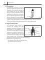
SERIAL NUMBER LOCATION AND IDENTIFICATION
Nameplate Label
COOLING AMPS. WITH PUMP
COMPR. OUTPUT
REFRIGERANT/TOTAL CHARGE
DESIGN PRESSURE LO/HI
PART NO./WEIGHT
SERIAL NO.
Nameplate Label Position
▲▲ XXXX ###
Month
Year
Model
Sequential
Number
© 2012 DENSO SALES CALIFORNIA, INC.
All rights reserved. This book may not be reproduced or copied, in
whole or in part, without the written permission of the publisher. DENSO
SALES CALIFORNIA, INC. reserves the right to make changes without
prior notice. MovinCool®, Office Pro® and SpotCool® are registered
trademarks of DENSO Corporation.
Table of Contents
Table of Contents
Operation Section
1. PRECAUTIONS FOR SAFETY
1.1
Foreword. . . . . . . . . . . . . . . . . . . . . . . . . . . . . . . . . . . . . . . . . . . . . . . . . . . . . . . . . . . . . . . . . . . . . . . 6
1.2
Definition of Terms . . . . . . . . . . . . . . . . . . . . . . . . . . . . . . . . . . . . . . . . . . . . . . . . . . . . . . . . . . . . . . . 6
1.3
General Precautions . . . . . . . . . . . . . . . . . . . . . . . . . . . . . . . . . . . . . . . . . . . . . . . . . . . . . . . . . . . . . . 6
2. SPECIFICATIONS
2.1
Exterior Dimension Diagram. . . . . . . . . . . . . . . . . . . . . . . . . . . . . . . . . . . . . . . . . . . . . . . . . . . . . . . . 7
2.2
Technical Specifications . . . . . . . . . . . . . . . . . . . . . . . . . . . . . . . . . . . . . . . . . . . . . . . . . . . . . . . . . . . 8
2.3
Characteristics . . . . . . . . . . . . . . . . . . . . . . . . . . . . . . . . . . . . . . . . . . . . . . . . . . . . . . . . . . . . . . . . . 10
3. CONSTRUCTION
3.1
Exterior Components . . . . . . . . . . . . . . . . . . . . . . . . . . . . . . . . . . . . . . . . . . . . . . . . . . . . . . . . . . . . 15
3.2
Internal Structure . . . . . . . . . . . . . . . . . . . . . . . . . . . . . . . . . . . . . . . . . . . . . . . . . . . . . . . . . . . . . . . 16
3.3
Basic Construction . . . . . . . . . . . . . . . . . . . . . . . . . . . . . . . . . . . . . . . . . . . . . . . . . . . . . . . . . . . . . . 18
3.4
Air Flow. . . . . . . . . . . . . . . . . . . . . . . . . . . . . . . . . . . . . . . . . . . . . . . . . . . . . . . . . . . . . . . . . . . . . . . 18
4. REFRIGERATION SYSTEM
4.1
Refrigeration System Construction . . . . . . . . . . . . . . . . . . . . . . . . . . . . . . . . . . . . . . . . . . . . . . . . . . 19
4.2
Compressor . . . . . . . . . . . . . . . . . . . . . . . . . . . . . . . . . . . . . . . . . . . . . . . . . . . . . . . . . . . . . . . . . . . 20
4.3
Condenser . . . . . . . . . . . . . . . . . . . . . . . . . . . . . . . . . . . . . . . . . . . . . . . . . . . . . . . . . . . . . . . . . . . . 22
4.4
Electronic Expansion Valve . . . . . . . . . . . . . . . . . . . . . . . . . . . . . . . . . . . . . . . . . . . . . . . . . . . . . . . 23
4.5
Evaporator . . . . . . . . . . . . . . . . . . . . . . . . . . . . . . . . . . . . . . . . . . . . . . . . . . . . . . . . . . . . . . . . . . . . 23
4.6
Accumulator . . . . . . . . . . . . . . . . . . . . . . . . . . . . . . . . . . . . . . . . . . . . . . . . . . . . . . . . . . . . . . . . . . . 24
4.7
High-Pressure Switch . . . . . . . . . . . . . . . . . . . . . . . . . . . . . . . . . . . . . . . . . . . . . . . . . . . . . . . . . . . . 24
5. ELECTRICAL SYSTEM
5.1
Circuit Diagram . . . . . . . . . . . . . . . . . . . . . . . . . . . . . . . . . . . . . . . . . . . . . . . . . . . . . . . . . . . . . . . . . 25
5.2
Control Box . . . . . . . . . . . . . . . . . . . . . . . . . . . . . . . . . . . . . . . . . . . . . . . . . . . . . . . . . . . . . . . . . . . . 26
5.3
Power Supply Requirements . . . . . . . . . . . . . . . . . . . . . . . . . . . . . . . . . . . . . . . . . . . . . . . . . . . . . . 27
5.4
Wall Mounted Controller (WMC) . . . . . . . . . . . . . . . . . . . . . . . . . . . . . . . . . . . . . . . . . . . . . . . . . . . . 28
5.5
Field-Supplied Millivolt Wall Thermostat (MWT) Connection . . . . . . . . . . . . . . . . . . . . . . . . . . . . . . 32
5.6
Warning Signal Connection (Output Signal Terminal L+ and L-) . . . . . . . . . . . . . . . . . . . . . . . . . . . 33
5.7
Fire Alarm Control Panel Connection (Input Signal Terminal E+ and E-) . . . . . . . . . . . . . . . . . . . . . 34
5.8
Basic Operation . . . . . . . . . . . . . . . . . . . . . . . . . . . . . . . . . . . . . . . . . . . . . . . . . . . . . . . . . . . . . . . . 35
5.9
Compressor Operation . . . . . . . . . . . . . . . . . . . . . . . . . . . . . . . . . . . . . . . . . . . . . . . . . . . . . . . . . . . 35
5.10 Electronic Expansion Valve Operation . . . . . . . . . . . . . . . . . . . . . . . . . . . . . . . . . . . . . . . . . . . . . . . 35
5.11 Evaporator Fan Motor Operation . . . . . . . . . . . . . . . . . . . . . . . . . . . . . . . . . . . . . . . . . . . . . . . . . . . 36
Table of Contents
5.12 Condenser Fan Motor Operation . . . . . . . . . . . . . . . . . . . . . . . . . . . . . . . . . . . . . . . . . . . . . . . . . . . 36
5.13 Internal Drain Pump Operation . . . . . . . . . . . . . . . . . . . . . . . . . . . . . . . . . . . . . . . . . . . . . . . . . . . . . 37
5.14 Anti-Frost Control . . . . . . . . . . . . . . . . . . . . . . . . . . . . . . . . . . . . . . . . . . . . . . . . . . . . . . . . . . . . . . . 37
5.15 Fan Motor Reverse Rotation Protection . . . . . . . . . . . . . . . . . . . . . . . . . . . . . . . . . . . . . . . . . . . . . . 37
5.16 Automatic Restart After Power Interruption (Automatic Recovery Function) . . . . . . . . . . . . . . . . . . 37
5.17 Relay Board . . . . . . . . . . . . . . . . . . . . . . . . . . . . . . . . . . . . . . . . . . . . . . . . . . . . . . . . . . . . . . . . . . . 38
5.18 Compressor . . . . . . . . . . . . . . . . . . . . . . . . . . . . . . . . . . . . . . . . . . . . . . . . . . . . . . . . . . . . . . . . . . . 40
5.19 Fan Motor . . . . . . . . . . . . . . . . . . . . . . . . . . . . . . . . . . . . . . . . . . . . . . . . . . . . . . . . . . . . . . . . . . . . . 41
5.20 Temperature Thermistor . . . . . . . . . . . . . . . . . . . . . . . . . . . . . . . . . . . . . . . . . . . . . . . . . . . . . . . . . . 42
5.21 Float Switch . . . . . . . . . . . . . . . . . . . . . . . . . . . . . . . . . . . . . . . . . . . . . . . . . . . . . . . . . . . . . . . . . . . 42
Table of Contents
Repair Section
6. TROUBLESHOOTING
6.1
Troubleshooting . . . . . . . . . . . . . . . . . . . . . . . . . . . . . . . . . . . . . . . . . . . . . . . . . . . . . . . . . . . . . . . . 43
6.2
Self-Diagnostic Codes . . . . . . . . . . . . . . . . . . . . . . . . . . . . . . . . . . . . . . . . . . . . . . . . . . . . . . . . . . . 44
6.3
Troubleshooting Chart . . . . . . . . . . . . . . . . . . . . . . . . . . . . . . . . . . . . . . . . . . . . . . . . . . . . . . . . . . . 50
6.4
Self-Diagnostic Code Display Operation and Control. . . . . . . . . . . . . . . . . . . . . . . . . . . . . . . . . . . . 56
6.5
Self-Diagnostic Code Records Display Operation (Only When Connected With WMC) . . . . . . . . . 57
6.6
Operational Status Display Control (Only When Connected With WMC) . . . . . . . . . . . . . . . . . . . . . 59
6.7
Initialize Fan Motor . . . . . . . . . . . . . . . . . . . . . . . . . . . . . . . . . . . . . . . . . . . . . . . . . . . . . . . . . . . . . . 61
6.8
TEST Mode. . . . . . . . . . . . . . . . . . . . . . . . . . . . . . . . . . . . . . . . . . . . . . . . . . . . . . . . . . . . . . . . . . . . 63
6.9
Basic Inspection . . . . . . . . . . . . . . . . . . . . . . . . . . . . . . . . . . . . . . . . . . . . . . . . . . . . . . . . . . . . . . . . 64
6.10 Inspection of Compressor. . . . . . . . . . . . . . . . . . . . . . . . . . . . . . . . . . . . . . . . . . . . . . . . . . . . . . . . . 65
6.11 Inspection of Electronic Expansion Valve Control Coil . . . . . . . . . . . . . . . . . . . . . . . . . . . . . . . . . . . 66
6.12 Inspection of Thermistor . . . . . . . . . . . . . . . . . . . . . . . . . . . . . . . . . . . . . . . . . . . . . . . . . . . . . . . . . . 66
6.13 Inspection of Wiring Connection . . . . . . . . . . . . . . . . . . . . . . . . . . . . . . . . . . . . . . . . . . . . . . . . . . . . 66
6.14 Inspection of Refrigeration System. . . . . . . . . . . . . . . . . . . . . . . . . . . . . . . . . . . . . . . . . . . . . . . . . . 67
7. DISASSEMBLY
7.1
Parts Construction . . . . . . . . . . . . . . . . . . . . . . . . . . . . . . . . . . . . . . . . . . . . . . . . . . . . . . . . . . . . . . 68
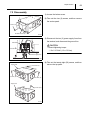
7.2
Disassembly . . . . . . . . . . . . . . . . . . . . . . . . . . . . . . . . . . . . . . . . . . . . . . . . . . . . . . . . . . . . . . . . . . . 69
7.3
Removal of Evaporator Fan Assembly . . . . . . . . . . . . . . . . . . . . . . . . . . . . . . . . . . . . . . . . . . . . . . . 71
7.4
Removal of Condenser Fan Assembly . . . . . . . . . . . . . . . . . . . . . . . . . . . . . . . . . . . . . . . . . . . . . . . 73
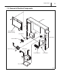
7.5
Removal of Electrical Components. . . . . . . . . . . . . . . . . . . . . . . . . . . . . . . . . . . . . . . . . . . . . . . . . . 75
8. REFRIGERATION SYSTEM REPAIR
8.1
Repair of Refrigeration System. . . . . . . . . . . . . . . . . . . . . . . . . . . . . . . . . . . . . . . . . . . . . . . . . . . . . 78
8.2
Removal of Refrigeration System Components . . . . . . . . . . . . . . . . . . . . . . . . . . . . . . . . . . . . . . . . 80
8.3
Charging the System with R-410A Refrigerant. . . . . . . . . . . . . . . . . . . . . . . . . . . . . . . . . . . . . . . . . 81
8.4
Refrigerant Charging Work . . . . . . . . . . . . . . . . . . . . . . . . . . . . . . . . . . . . . . . . . . . . . . . . . . . . . . . . 86
9. REASSEMBLY
9.1
Reassembly of Unit. . . . . . . . . . . . . . . . . . . . . . . . . . . . . . . . . . . . . . . . . . . . . . . . . . . . . . . . . . . . . . 88
9.2
Compressor Mounting . . . . . . . . . . . . . . . . . . . . . . . . . . . . . . . . . . . . . . . . . . . . . . . . . . . . . . . . . . . 88
9.3
Evaporator Fan Assembly . . . . . . . . . . . . . . . . . . . . . . . . . . . . . . . . . . . . . . . . . . . . . . . . . . . . . . . . 88
9.4
Condenser Fan Assembly . . . . . . . . . . . . . . . . . . . . . . . . . . . . . . . . . . . . . . . . . . . . . . . . . . . . . . . . 88
9.5
Wiring Notice . . . . . . . . . . . . . . . . . . . . . . . . . . . . . . . . . . . . . . . . . . . . . . . . . . . . . . . . . . . . . . . . . . 88
9.6
Perform an Inspection. . . . . . . . . . . . . . . . . . . . . . . . . . . . . . . . . . . . . . . . . . . . . . . . . . . . . . . . . . . . 88
6
Operation Section
1. PRECAUTIONS FOR SAFETY
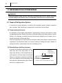
1.1 Foreword
• This manual has been published to service the MovinCool CM 25. Use this manual only when
servicing the CM 25.
1.2 Definition of Terms
WARNING
CAUTION
NOTE
Describes precautions that should be observed in order to prevent injury to
the user during installation or unit operation.
Describes precautions that should be observed in order to prevent damage to
the unit or its components, which may occur during installation or unit
operation if sufficient care is not taken.
Provides additional information that facilitates installation or unit operation.
1.3 General Precautions
WARNING
• All electrical work should only be performed by qualified electrical technician. Repair to
electrical components by non-certified technicians may result in personal injury and/or
damage to the unit. All electrical components replaced must be genuine MovinCool parts,
purchased from an authorized reseller.
• Disconnect power supply from the unit before performing any service.
• Before replacing any refrigeration components, recover the refrigerant using standard
recovery procedures and equipment.
• When handling refrigerant, always wear proper eye protection and do not allow the
refrigerant to come in contact with your skin.
• Do not expose refrigerant to an open flame.
• The power supply for this unit should be a dedicated single outlet circuit with a UL
recognized short-circuit and ground-fault protective breaker to prevent electrical shock
from the unit.
• When brazing any tubing, always wear eye protection, and work only in a well ventilated
area.
• Be careful of any sharp edges when working on this unit.
Operation Section
7
2. SPECIFICATIONS
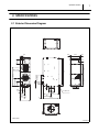
2.1 Exterior Dimension Diagram
0.9
2.4
0.8
10.2
0.9
19.7
53
51.3
DIA. 13.8
22.4
DIA. 0.6
6.5
14.4
DIA. 12
34.6
1.1
4
0.6
17.8
0.8
3.4
DIA. 12
4 x DIA. 0.6
29.8
9.5
16
10.7
4
31.5
20
UNIT: inch
ILL00663-00
Operation Section
8
2.2 Technical Specifications
Wall Mounted Controller (WMC) with LCD
Operation
display
Electronic Features
Electronic Characteristics
Control
Electronic with Inverter Circuit
Voltage Requirement
Single-Phase 208/230 V 60 Hz
Min.- Max. Voltage
Recommended Fuse Size
Min. 198 V, Max. 253 V
20 A
Cooling Capacity and Power Consumption
Total Cooling Capacity*1
Sensible Cooling
Evaporator: 80°F (27°C), 50% RH/
Condenser: 95°F (35°C), 50% RH
Power
Capacity*1
Consumption*1
Current Consumption*1
Power Factor
Total Cooling
Condenser: 95°F (35°C), 50% RH
Capacity*1
2.90/2.90 kW
13.6/12.6 A
25000/25000 Btu/h (7320/7320 W)
18900/18900 Btu/h (5580/5580 W)
Power Consumption*1
3.20/3.20 kW
Current Consumption*1
15.0/15.0 A
Power Factor
98/98%
SEER*1
14/14
Compressor
Refrigerant Circuit
18000/18000 Btu/h (5280/5280 W)
98/99%
Capacity*1
Sensible Cooling
Evaporator: 72°F (22°C), 50% RH/
25000/25000 Btu/h (7320/7320 W)
Compression
Type
Hermetic Swing Inverter
Evaporator
Plate Fin
Condenser
Plate Fin
Refrigerant Control
Type of Fan
Centrifugal Fan
High
850/950 CFM (1445/1615 m3/h)
Low
700/800 CFM (1190/1360 m3/h)
Air Flow
Evaporator
Electronic Expansion Valve
Max. External Static Pressure
0.6 IWG (150 Pa)
Motor Output
0.21 kW
Type of Fan
Centrifugal Fan
High
1490/1600 CFM (2530/2720 m3/h)
Low
1190/1300 CFM (2020/2210 m3/h)
Air Flow
Condenser
Max. External Static Pressure
0.5 IWG (125 Pa)
Motor Output
0.35 kW
Type
R-410A
Refrigerant
Amount
2.31 lb (1.05 kg)
Operation Section
9
• Dry contact type (recommended)
• No-voltage contact input/Contact
Fire Alarm Input
Signal Connection
resistance less than 100 ohm
Warning Signal Output
2 A at 30 V DC/AC max. with resistive load
W x D x H (without flange)
53 x 32 x 20 in (1346 x 813 x 508 mm)
W x D x H (with flange)
57 x 36 x 20 in (1448 x 914 x 508 mm)
Dimension
Weight
Net/Shipping
310/353 lb (140/160 kg)
Pump Rate
5.0 gal/h (19 L/h)
Internal Drain Pump Capacity
Head
4 ft (1.2 m)
Max. Inlet Air
95°F (35°C), 50% RH
Min. Inlet Air
60°F (15.5°C), 50% RH
Max. Inlet Air
113°F (45°C)
Min. Inlet Air
50°F (10°C)
Evaporator
Operating Condition Range
Condenser
Cold
Maximum Duct Length
Duct*2
Hot Duct*2
120 ft (36.6 m)
90 ft (27.4 m)
Measured at 1 m under the
Maximum Sound Level
ceiling with evaporator duct and
55/55 dB (A)
ceiling tile.
• Specifications are subject to change without notice.
< NOTE >
*1 : With two 20-foot (6.1 m) ducts containing one 90° bend each, supply grill and return grill with filter {0.30 IWG (75 Pa)
external static pressure} on high fan speed.
*2 : Confirm pressure drop of duct, grills, and filter with manufactures specifications.
Operation Section
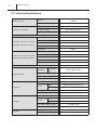
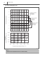
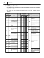
2.3 Characteristics
• Value range for each outdoor temperature shown in the graphs is based on the compressor speed.
(1) How to read the characteristics
< Example >
Condition:
Cooling Capacity:
Evaporator Inlet Air Dry Bulb
: 77 °F (25 °C)
Evaporator Inlet Air Wet Bulb
: 59 °F (15 °C)
Condenser Inlet Air Temperature : 95 °F (35 °C)
Max: 24000 Btu/h
Min: 8000 Btu/h
40
Condenser Inlet Air
Temperature
50°F (10°C)
Cooling Capacity (x103 Btu/h)
35
30
25
Condenser Inlet Air
Temperature
95°F (35°C)
20
15
10
Condenser Inlet Air
Temperature
115°F (46°C)
5
Evaporator
Inlet Air Dry Bulb Temp. °F (°C)
10
95 (35)
86 (30)
77 (25)
68 (20)
59 (15)
41
(5)
50
(10)
59
(15)
68
(20)
77
(25)
Evaporator Inlet Air Wet Bulb Temp. °F (°C)
< NOTE >
Condenser inlet air temperatures are at 50% relative humidity.
IILL00675-00
Operation Section
11
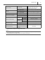
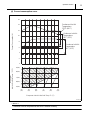
(2) Cooling capacity curve
40
Condenser Inlet Air
Temperature
50°F (10°C)
Cooling Capacity (x103 Btu/h)
35
30
25
Condenser Inlet Air
Temperature
95°F (35°C)
20
15
Condenser Inlet Air
Temperature
115°F (46°C)
10
Evaporator
Inlet Air Dry Bulb Temp. °F (°C)
5
95 (35)
86 (30)
77 (25)
68 (20)
59 (15)
41
(5)
50
(10)
59
(15)
68
(20)
77
(25)
Evaporator Inlet Air Wet Bulb Temp. °F (°C)
IILL00676-00
< NOTE >
Condenser inlet air temperatures are at 50% relative humidity.
Operation Section
12
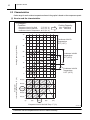
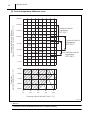
(3) Power consumption curve
4.0
3.5
Condenser Inlet Air
Temperature
115°F (46°C)
Power Consumption (kW)
3.0
2.5
Condenser Inlet Air
Temperature
95°F (35°C)
2.0
1.5
Condenser Inlet Air
Temperature
50°F (10°C)
1.0
0.5
Evaporator
Inlet Air Dry Bulb Temp.°F (°C)
0
95(35)
86(30)
77(25)
68(20)
59(15)
50
(10)
59
(15)
68
(20)
77
(25)
86
(30)
95
(35)
Evaporator Inlet Air Wet Bulb Temp.°F (°C)
ILL00677-00
< NOTE >
Condenser inlet air temperatures are at 50% relative humidity.
Operation Section
13
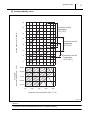
(4) Current consumption curve
16
Condenser Inlet Air
Temperature
115°F (46°C)
14
Current Consumption (A)
12
Condenser Inlet Air
Temperature
95°F (35°C)
10
8
Condenser Inlet Air
Temperature
50°F (10°C)
6
4
2
Evaporator
Inlet Air Dry Bulb Temp. °F (°C)
0
95(35)
86(30)
77(25)
68(20)
59(15)
50
(10)
59
(15)
68
(20)
77
(25)
86
(30)
95
(35)
Evaporator Inlet Air Wet Bulb Temp.°F (°C)
ILL00678-00
< NOTE >
Condenser inlet air temperatures are at 50% relative humidity.
Operation Section
14
(5) Cool air temperature difference curve
Temperature Difference Between
Evaporator Inlet and Outlet Air (Delta-T) °F (°C)
28.8(16)
25.2(14)
Condenser Inlet Air
Temperature
50°F (10°C)
21.6(12)
18.0(10)
Condenser Inlet Air
Temperature
95°F (35°C)
14.4 (8)
10.8 (6)
Condenser Inlet Air
Temperature
115°F (46°C)
7.2 (4)
3.6 (2)
Evaporator
Inlet Air Dry Bulb Temp.°F (°C)
95(35)
86(30)
77(25)
68(20)
59(15)
41
(5)
50
(10)
59
(15)
68
(20)
77
(25)
Evaporator Inlet Air Wet Bulb Temp.°F (°C)
ILL00679-00
< NOTE >
Condenser inlet air temperatures are at 50% relative humidity.
Operation Section
15
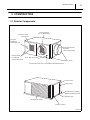
3. CONSTRUCTION
3.1 Exterior Components
Cool Air Exhaust
(12.0 in.Dia.Flange)
Condenser (Hot)
Air Exhaust
Connection
For Optional
Condensate Pump
Evaporator (Room)
Air Intake
(12.0 in.Dia.Flange)
Fixing Position
For Optional
Condensate Pump
Drain Pipe For Pump
Mounting Holes
Condensate Pan Drain For Gravitational Drain/Maintenance
Service Panel
Stop Switch
Wall Mounted Controller/
Millivolt System Wire Inlet
Signal Wire inlet
Condenser Air Intake
Power Cord Inlet
ILL00665-00
16
Operation Section
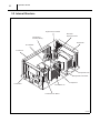
3.2 Internal Structure
High-Pressure Switch
Electronic
Expansion Valve
Compressor
Overload Relay
Evaporator
Accumulator
Condenser
Evaporator Fan
Evaporator Fan Motor
Control Box
Compressor
Condenser Fan
Condenser Fan Motor
I003141
Operation Section
17
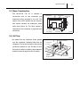
3.3 Basic Construction
• The
MovinCool
CM
25
is
compact
in
construction due to the condenser and
Control Box
Condenser
Evaporator
evaporator being enclosed in one unit. The
interior of the unit is divided into two sections.
One section contains the evaporator which
cools room interior air. The other section is
comprised of the condenser, compressor and
control box.
Condenser
Fan Motor
Evaporator
Fan Motor
I003158
3.4 Air Flow
• Air drawn from the condenser intake passes
over the condenser, extracting heat from the
refrigerant. The hot air is blown out through the
Condenser Intake
Condenser
Exhaust
condenser exhaust air vent. Air taken in from
the room air intake is cooled by the evaporator
and then blown through the cool air supply.
Cool Air
Supply
(Evaporator)
Room
Air Intake
I003153
18
Operation Section
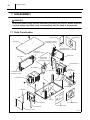
4. REFRIGERATION SYSTEM
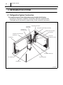
4.1 Refrigeration System Construction
The component parts of the refrigeration system include the following:
• Compressor, Evaporator, Condenser, Accumulator, Electronic expansion valve
These parts are all connected by copper tubing. All the connections are brazed.
Condenser
Outlet Pipe
Compressor
Discharge Pipe
Evaporator Inlet Pipe
Evaporator Outlet Pipe Assembly
High-Pressure Switch
Evaporator
Compressor Suction Pipe
(Insulated)
Electronic
Expansion Valve
Condenser
Condenser Inlet Pipe
Connecting Pipe
Accumulator
Compressor
ILL00681-00
Operation Section
19
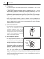
Flow of Refrigerant
CTS1 (Condenser Thermistor)
OLC (Compressor Overload Relay)
MF1
(Condenser
Fan Motor)
CTS3 (Evaporator Pipe Outlet Thermistor)
Accumulator
Evaporator
Condenser
Compressor
MF2
(Evaporator
Fan Motor)
HPRS
(High-Pressure Switch)
ODS
(Condenser Inlet Air Thermistor)
EXV
(Electronic Expansion Valve)
RTS2
(Evaporator Inlet
Air Thermistor)
CTS2
(Evaporator Pipe
Inlet Thermistor)
Wall Mounted Controller (WMC)
RTS1 (WMC Room Thermistor)
ILL00680-00
20
Operation Section
4.2 Compressor
• The CM 25 is equipped with a variable speed compressor, which is driven by state of the art
inverter technology.
• A variable speed compressor automatically adjusts its speed as the heat load in the room
changes. With its soft start up, a variable speed compressor reduces start up wear on the
compressor and eliminates in-rush current resulting in no dip in the power supply.
• As an AC power signal is supplied to the inverter circuit, it is then rectified and converted into a
DC power signal with modulated frequency. This modulated frequency controls the speed of the
compressor.
• As the compressor speed decreases, the amount of refrigerant entering the evaporator also
decreases. This results in a more comfortable environment as the unit provides the appropriate
amount of desired cooling. As a result, the room is controlled with a much smaller temperature
swing than traditional control methods.
(1) Compressor construction
• The construction of a swing type compressor is
divided into two mechanisms; the drive
mechanism (compressor motor), and the
compression mechanism (compressor). When
the rotor shaft of the motor (drive mechanism)
turns, the piston (compression mechanism)
rotates to compress the refrigerant.
I003143
(2) Basic compressor operation
• The piston (compression mechanism) is set
eccentrically with a certain distance given from
the axis of the center of the cylinder. The
piston turns to compress the refrigerant in the
space between the cylinder and eccentrically
mounted piston. A swing bush absorbs the
lateral blade movement under piston action.
The blade partitions the space between the
Discharge Valve
Discharge
Orifice
Swing Bush
Suction Orifice
Shaft
Piston
Cylinder
I003184
suction side and the discharge side to keep
compressed refrigerant from returning to the suction side. There is no suction valve. The
discharge valve is designed not to open until the pressure of the refrigerant within the cylinder
reaches or exceeds discharge side pressure. As a result, the discharge valve prevents the
backward flow of refrigerant gas.
Operation Section
21
(3) Operation
1) Start of compression
Discharge
Valve
1) The cylinder is filled with low pressure gas.
2) Since pressure in the discharge chamber is higher
than in the cylinder, the discharge valve is kept
closed.
Piston
Cylinder
I003185
2) Suction and compression
Discharge
Valve
1) The pressure in the cylinder increases gradually.
2) Refrigerant suction begins on the suction side of
the cylinder.
3) The discharge valve remains closed.
Piston
Cylinder
I003186
3) Discharge
Discharge
Valve
1) The pressure in the cylinder exceeds that in the
discharge chamber, and the discharge valve
opens.
2) On the suction side, refrigerant suction continues.
Piston
Cylinder
I003187
4) Completion of compression
Discharge
Valve
1) When compression is completed, all of the
refrigerant has been drawn from the suction
chamber.
2) Operation then returns to step 1) (Start of
Piston
compression) and the above process of suction
Cylinder
and
compression
succession.
I003188
continues
repeatedly
in
22
Operation Section
(4) Compressor lubrication
• The lubrication system is comprised of a
hollow shaft, an oil scraper mounted at the
bottom end of a shaft journal (shaft bearing),
Rotor
and the lubrication groove for the shaft journal.
The lubrication groove is wider than the oil
orifice. When the shaft turns, oil is scraped
upward by the oil scraper along the inside
Hollow Shaft
Eccentric Shaft
Cylinder
Piston
diameter of the hollow shaft. The oil is fed
through the oil orifice by centrifugal force, then
supplied to the lubrication groove for each
shaft journal, lubricating the bearing. In this
lubrication system, oil enters into each bearing
separately and returns to the oil reservoir. This
system
effectively
temperature
increases,
prevents
and
Oil Feed Groove
Oil Orifice
Oil Scraper
bearing
offers
high
I003183
reliability. In addition, the specially treated
shaft journal keeps the bearing from being damaged during high temperature operation.
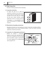
4.3 Condenser
• The condenser is a heat exchanger with
copper tubes that are covered with thin
aluminum projections called plate fins.
• Heat is given off and absorbed by air being
pulled across the condenser fins by the
centrifugal fan, and then expelled through the
exhaust air duct.
I003144
Operation Section
23
4.4 Electronic Expansion Valve
• The electronic expansion valve causes rapid
refrigerant
expansion
by
injecting
"high-
temperature, high-pressure liquid refrigerant"
from the condenser through a small orifice. The
Valve Spring
Magnet
Delivery Screw
solenoid valve adjusts the refrigerant quantity
according to the evaporator inlet air and outlet
air thermistors such that the mist refrigerant
Valve Holder
Stopper
Valve
resultant "low-temperature, low-pressure mist
refrigerant" is then sent to the evaporator. A
Spring
Refrigerant
Flow
Control Coil
can undergo heat exchange in the evaporator
under optimal conditions.
Valve
I003162
4.5 Evaporator
• The evaporator is a heat exchanger covered
with plate fins. Heat is removed from the air
being pulled across the evaporator by the
centrifugal fan. The resulting cool air is
expelled through the cool air vent.
I003145
24
Operation Section
4.6 Accumulator
• The accumulator is mounted on the suction
from Evaporator
gas piping between the evaporator and the
compressor. The accumulator separates the
liquid refrigerant from the gas refrigerant,
allowing only the gas refrigerant to enter the
compressor. In the accumulator, suction gas is
led into a cylindrical vessel where the speed of
to Compressor
the gas is decreased. This process separates
I000514
the refrigerant contained in the gas by the force
of gravity, causing the refrigerant to accumulate at the bottom of the vessel. As a result, the
compressor is protected from possible damage caused by liquid refrigerant intake.
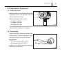
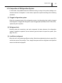
4.7 High-Pressure Switch
• The
high-pressure
condenser
and
switch
compressor
prevents
from
the
Pressure of Refrigerant
being
damaged by excessively high pressure in the
Snap Disk
Movable Point
high-pressure line of the refrigeration cycle.
The switch is normally closed. The snap disk
Stationary Point
responds to the variations in pressure and, if
Case
pressure is abnormally high, the snap disk
moves down to push the pin down, causing the
Molding by Resin
internal contacts to open. This interrupts the
ground signal at the relay board which turns the compressor off.
• Possible causes of this trouble include:
- The condenser air filter is dirty, and restricting air flow.
- The condenser fan motor is defective.
Pin
Terminal
Lead Wires
I001768
Operation Section
25
5. ELECTRICAL SYSTEM
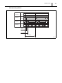
5.1 Circuit Diagram
WMC
MDP
2
1
CONTROL
CIRCUIT
RTS2 CTS3 CTS2 CTS1 ODS
CN
RTS1
G
1
EXV
5
1
P C4 G4
6
HPRS
Fire
Alarm Output
Input Signal
Millivolt
Thermostat
E+ E- L+ L-
C Y1 Y2 G G1
2
OLC
SW
FLTS
1
2
G
1
TB2
MF2
3
1
CN17
1
1
CN20
4
2
CN19
1
3
CN5
1
2
CN6
14
CN7
11
CN8
31
CN9
5 2
CN10
12
14
CN11
CN14
DIP SWITCH
CN18
12
1
CN13 CN12
1
5
1
RB
CN2
Power
Supply
Circuit
F3
STI
Module
6
4
CN
106
CN
105
CN1 2
CN CN
101 102
CN CN
104 103
CN3
F2
F1
CN
107
G
CN4
2
15
2
3
1
1
IND
NF
MC
G
MF1
TB1
G
R
G
G
T
AC 208/230 V G
1-PHASE, 60 Hz
DIP SWITCH
DSW1 DSW2
DSW1
DSW3
DSW4
1 2 3 4
1 2 3 4
OFF (DEFAULT)
#1 ON : ENABLES MILLIVOLT WALL THERMOSTAT (MWT)
OFF : ENABLES WALL MOUNTED CONTROLLER (WMC)
#2
: N/A
DSW2
1 2
1 2
DSW3
#1 : ON
#2 : ON
OFF
#3, #4
: TEST MODE
: DISABLES INTERNAL DRAIN PUMP
: ENABLES INTERNAL DRAIN PUMP
: N/A
DSW4 : N/A
#1 : ON : INITIALIZES FAN MOTORS
#2
: N/A
TB1
Terminal Block 1
FLTS
Float Switch
TB2
Terminal Block 2
WMC
Wall Mounted Controller
MC
Compressor Motor
RB
Relay Board
OLC
Compressor Overload Relay
F1
Fuse 1
MF1
Condenser Fan Motor
F2
Fuse 2 For Condenser Fan Motor
MF2
Evaporator Fan Motor
F3
Fuse 3 For Evaporator Fan Motor
MDP
Internal Drain Pump Motor
RTS1
WMC Room Thermistor
EXV
Electronic Expansion Valve
RTS2
Evaporator Inlet Air Thermistor
NF
Noise Filter
ODS
Outdoor Thermistor (Condenser Inlet Air Thermistor)
IND
Inductor Coil
CTS1
Condenser Thermistor
SW
Stop Switch
CTS2
Evaporator Pipe Inlet Thermistor
Connector For Optional Condensate Pump
CTS3
Evaporator Pipe Outlet Thermistor
CN
HPRS
High-Pressure Switch
G
Ground
ILL00682-00
26
Operation Section
5.2 Control Box
RB: Relay Board
TB1: Terminal Block 1
NF: Noise Filter
IND: Inductor Coil
TB2: Terminal Block 2
I003190
Operation Section
27
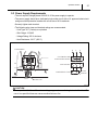
5.3 Power Supply Requirements
• The unit requires a single-phase 208/230 V, 60 Hz power supply to operate.
• The power supply should be a dedicated single outlet circuit with a UL approved short-circuit
and ground fault protective breaker with a fuse size of 20 A maximum.
• Securely tighten each terminal.
• The following wire sizes and electrical ratings are recommended:
- Cord Type: SJT (3 wires) or equivalent
- Wire Gauge: 12 AWG
- Voltage Rating: 300 V minimum
- Heat Resistance: 221°F (105°C)
Terminal Block
R
T
G
Circuit Breaker with
Ground-Fault Protection
Fuse 20 A Max.
G
R
T
Terminal Block of Unit
R
T
G
Ground
Terminal
Power Cord
I003159
CAUTION
Use a specified 20 A fuse. Do not use wiring, copper wire or soldering instead of the fuse. The
use of non-specified fuses can cause machine failure or fire.
Operation Section
28
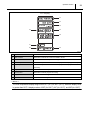
5.4 Wall Mounted Controller (WMC)
• The WMC for this unit should be mounted within the room close to the return air grill to provide
convenient system control.
LCD Display
Control Panel
5
7
1
2
3
4
6
4.8 in (120 mm)
8
10
9
4.8 in (120 mm)
0.6 in (15 mm)
I003163
1
ON/OFF button
Activates (LED illuminates green) or deactivates unit operation.
2
MODE button
Activates COOL or FAN ONLY operation.
3
FAN MODE button
Activates fan mode RUN or AUTO.
RUN: Fan operates continuously during COOL mode even after the room
temperature reaches the set point temperature.
RUN mode is automatically selected when FAN ONLY mode is selected.
AUTO: Fan automatically stops during COOL mode after the room temperature
reaches the set point temperature.
Fan automatically operates when the room temperature is above the set
point temperature.
4
FAN SPEED button
Activates fan speed High or Low.
5
UP () and DOWN () button Increases or decreases the temperature set point during COOL mode. Selects
each item when setting the clock or program.
6
PROGRAM button
Sets or displays program.
7
SET TIME button
Sets clock (day and time).
8
ENTER button
Accepts selection and goes to the next step.
9
RUN/STOP button
Activates or deactivates program(s).
10
RESET button
• Clears self-diagnostic codes.
• Returns to “Day of the week” for “ON” (start) program setting during program
editing mode.
• Clears all program memory during program editing mode by pressing and
holding the RESET button for 3 seconds.
Operation Section
29
LCD Display
11
12
13
14
15
16
17
19
18
I003164
11
COOL or FAN ONLY
Illuminates to indicate COOL on or FAN ONLY on.
12
RUN or AUTO
Illuminates to indicate fan mode set to RUN or AUTO.
13
HI or LO
Illuminates to indicate fan speed set to High or Low.
14
Room temperature
Illuminates temperature in either Fahrenheit (°F) or Celsius (°C) (See Note).
15
Set temperature
Illuminates temperature in either Fahrenheit (°F) or Celsius (°C) in COOL mode
(See Note).
16
Day of the week and time
Illuminates to indicate day of the week and time.
17
Clock symbol
Illuminates to indicate program is running.
18
Key symbol
Illuminates to indicate keypad locked.
19
CHECK
Illuminates with self-diagnostic codes.
< NOTE >
The room temperature display range is from 16°F (-9°C) to 140°F (60°C). When the display value
is greater than 99°F, it displays values of 00F (for 100°F), 01F (for 101°F), and 09F (for 109°F).
30
Operation Section
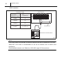
• WMC connection
Connection Table
Wall Mounted
Controller
Wire No. (Color)
Unit Terminal
Unit
Terminal No.
C4
G4 (Black)
G4
Shield Conductor
(Green)
G
(Ground Screw)
G1
G
Y2
Y1
RC
C4 (White)
P
C4
G4
P
E+
E–
L+
L–
P (Red)
G
Ground Screw
Wall Mounted Controller (WMC)
I003165
< NOTE >
If the wiring needs to be extended, a maximum extension wire can be extended up to 316 feet.
Shield wire 16-22 AWG is recommended for use as an extension wire to reduce noise
interference.
Recommended extension cord: Shield wire 16-22 AWG, length 316 feet maximum
Operation Section
31
For WMC supplied with the CM 25 serial number from 0113XXXXC25 to present
• If the reading of the room temperature value is not accurate, adjustment can be done by setting
the DIP switch located inside the WMC using the table shown below as reference.
• Label of model name is located on the back cover of WMC.
CAUTION
To avoid static electricity, do not touch the solder joints or the non-insulated parts on the
controller board.
DIP Switch Position
DIP Switch
Temperature
ON
1
2
3
4~8
Values
OFF
OFF
OFF
OFF
OFF
DEFAULT
OFF
ON
OFF
OFF
+1
OFF
OFF
ON
OFF
+2
OFF
ON
ON
OFF
+3
ON
ON
OFF
OFF
-1
ON
OFF
ON
OFF
-2
ON
ON
ON
OFF
-3
1
2
3
4
5
6
7
8
ILL00683-00
< NOTE >
Set the DIP switch 4 to 8 to OFF positions.
32
Operation Section
5.5 Field-Supplied Millivolt Wall Thermostat (MWT) Connection
• The CM 25 is equipped with terminals for connection to the MWT. The MWT can be installed for
convenient access in any room.
- Use with a single- and multi-stage system wall thermostat.
Thermostat type: Millivolt system
- Most wall thermostats provide these basic functions:
Fan Mode: On/Auto (Selects the desired fan mode.)
System: Cool/Heater (Selects Cool only.)
- Unit receives signals from the MWT to perform the following operations.
Multi-Stage System
Single-Stage System
Terminal No.
Function
Terminal No.
Function
RC
Common
RC
Common
Y1
Cool MIN
Y (Y2)
Cool
Y2
Cool MAX
G
Fan HI
G
Fan HI
G1
Fan LO
G1
Fan LO
Unit Terminal
Unit Terminal
G1
G
Y2
Y1
RC
P
C4
G4
E+
E–
L+
L–
G1
G
Y2
Y1
RC
P
C4
G4
E+
E–
L+
L–
G
Ground Screw
Wall Thermostat
(Multi-Stage System)
G
Ground Screw
Wall Thermostat
(Single-Stage System)
I003166
< NOTE >
Terminal No. G1 is used only with the MWT that has Fan Hi-Lo speed control.
Use the recommended extension cord size from 16 AWG to 26 AWG for a solid wire.
Operation Section
33
5.6 Warning Signal Connection (Output Signal Terminal L+ and L-)
• The unit is equipped with a warning signal output relay type (Form-C, normal open dry contact)
that can be used to monitor the failure condition.
• The relay contactor is closed when the following conditions have occurred:
- Condensation overflows
- Temperature sensor fails
- Cooling function fails
• The relay output contactor is rated 2 A at 30 VDC or 2 A at 30 VAC maximum with resistive load,
and is compatible with various warning devices such as alarm speakers, light indicators, etc.
< NOTE >
Use the recommended warning signal wire size from 16 AWG to 26 AWG for a solid wire, or 16
AWG to 22 AWG for a stranded wire.
• Connect the warning signal wires to terminal L+ and L- in the unit control box according to the
labels shown below.
Unit Terminal
Relay Output Contactor
G1
G
Y2
Y1
RC
P
C4
G4
E+
E–
L+
L–
Signal
Warning Device
ILL00286-00
34
Operation Section
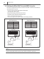
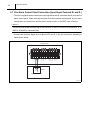
5.7 Fire Alarm Control Panel Connection (Input Signal Terminal E+ and E-)
• The unit is equipped with a normal open input signal that can be connected directly from the fire
alarm control panel. When receiving the signal from the fire alarm control panel, the unit turns
off and does not turn back on until the power source is reset, or the MWT turns off and on.
< NOTE >
Use the recommended fire alarm signal wire size from 16 AWG to 26 AWG for a solid wire, or 16
AWG to 22 AWG for a stranded wire.
• Connect the fire alarm signal wires to terminal E+ and E- in the unit control box according to
labels shown below.
Unit Terminal
G1
G
Y2
Y1
RC
P
C4
G4
E+
E–
L+
L–
Signal
Open Dry Contact
Fire Alarm Device
ILL00287-00
Operation Section
35
5.8 Basic Operation
• The following components are controlled based on settings and signals from the WMC or MWT
in accordance with signals from various sensors: compressor, evaporator fan motor, condenser
fan motor, electronic expansion valve, internal drain pump.
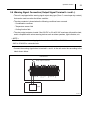
5.9 Compressor Operation
(1) Startup speed control
• The compressor operates at 40 rps for 120
the refrigeration cycle stabilizes, the inverter
controls compressor speed.
Start of
Compressor
Operation
Compressor Speed (rps)
seconds after cooling operation begins. Once
120 sec
40
Transition to
Normal Control
Time
I003169
< NOTE >
While under startup speed control, the unit continues to operate to protect the refrigerant system,
even if cooling operations are suspended by the WMC or MWT.
When startup speed control is completed and cooling operation is suspended within 120 seconds,
the "COOL" display flashes for the WMC.
(2) Delay control
• After the power supply is turned on, or after the compressor is stopped, compressor startup is
delayed for a fixed time period to prevent overloading the compressor.
Specifications:
- Time Delay: 120 sec.
5.10 Electronic Expansion Valve Operation
• The electronic expansion valve automatically controls its valve position to optimize the
refrigerant cycle.
36
Operation Section
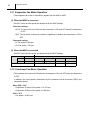
5.11 Evaporator Fan Motor Operation
• The evaporator fan motor is controlled by signals from the WMC or MWT.
(1) When the WMC is connected
• ON/OFF control and fan speed are determined by the WMC settings.
Fan motor settings
- AUTO: The fan motor turns ON when the compressor is ON, and OFF when the compressor
is OFF.
- RUN: The fan motor continuously operates, regardless of whether the compressor is ON or
OFF.
Fan speed settings
- HI: Fan speed = 880 rpm
- LO: Fan speed = 780 rpm
(2) When the MWT is connected
• ON/OFF control and fan speed are determined by the MWT settings.
Terminal No.
Function
Signal Input
G
Fan HI
OFF
OFF
ON
ON
G1
Fan LO
OFF
ON
OFF
ON
HI: 880 rpm
LO: 780 rpm
Evaporator fan motor speed
OFF
5.12 Condenser Fan Motor Operation
• The condenser fan motor turns ON when the compressor is ON, and OFF when the compressor
is OFF.
In addition, fan motor speed is determined by the condenser inlet air thermistor (ODS), and
compressor speed.
When ODS 30°C
- Compressor 30-40 rps: Fan speed = LO 710 rpm
- Compressor 40-90 rps: Fan speed = HI 865 rpm
ODS < 30°C
- Fan speed = HI 865 rpm
Operation Section
37
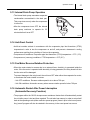
5.13 Internal Drain Pump Operation
• The internal drain pump evacuates evaporator
condensation accumulated in the drain pan.
This pump turns on only when the compressor
is turned on.
• After the compressor turns OFF, the internal
drain pump continues to operate for 2.5
minutes before it turns OFF.
I000523
5.14 Anti-Frost Control
• Anti-frost controls activate in accordance with the evaporator pipe inlet thermistor (CTS2)
temperature in order to turn the compressor on and off, and prevent a decrease in cooling
performance resulting from a buildup of frost on the evaporator.
• Compressor off conditions: Evaporator pipe inlet thermistor (CTS2) temperature 27°F (-3°C)
• Compressor on (recovery) conditions: CTS2 temperature 43°F (6°C)
5.15 Fan Motor Reverse Rotation Protection
• When the motor rotates in reverse due to an external force, electricity is generated inside the
motor. If the fan motor is operated while electricity is being generated, the relay board built into
the fan motor will be damaged.
To prevent damage to the relay board, the unit turns OFF when either the evaporator fan motor,
or condenser fan motor rotates in reverse.
- Unit OFF conditions: Reverse rotation speed is at or above 760 rpm
- Unit ON conditions: Automatic recovery when reverse rotation speed is below 760 rpm
5.16 Automatic Restart After Power Interruption
(Automatic Recovery Function)
• The program within the CM 25 microprocessor contains a feature that will automatically restart
the unit after power is lost and then regained. The unit also has memory in order to return itself
back to the operating mode (either manual or preset program) it was in prior to the loss of power.
Any “preset” program will also be retained in the memory in the event power loss occurs.
Operation Section
38
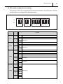
5.17 Relay Board
• The relay board controls components such as the compressor and fan motor based on both
signals received from the WMC or MWT, as well as signals from various sensors.
The relay board is equipped with a compressor control device called the “STI module”.
The relay board also contains fuses and a DIP switch.
CN12
CN13
CN11
CN14
CN9
CN10
CN8
CN7
CN5
CN6
CN19
CN21
CN20
CN17
LED 1~6
LED 7
1
STI Module
6
CN4
CN2
Fuse 3
CN101
CN102
Fuse 2
CN1
CN103
CN104
CN105
CN106
CN107
Fuse 1
CN3
CN18
DIP Switch
Fuse 4
Heatsink
STI Module
ILL00688-00
(1) Fuse
Fuse
Function
Specification
F1
Main fuse
20 A, 250 VAC
F2
Fuse for control circuit
1 A, 250 VAC
F3
Fuse for condenser fan motor
3.15 A, 250 VAC
F4
Fuse for evaporator fan motor
3.15 A, 250 VAC
Operation Section
39
(2) DIP switch configuration and setting
• The controller of the unit is equipped with DIP switches that default in the OFF position. The DIP
switch can be set to configure the following functions.
ON
OFF
1
2
DSW1
1
2
DSW2
1
2
3
4
1
DSW3
2
3
4
DSW4
I003192
Switch
Switch
Name
Number
Function
ON
Enables the MWT.
OFF
Enables the WMC.
1
DSW1
ON
2
No function.
OFF
ON
Initializes setting of the condenser and evaporator fan motors after replacing the fan motors.
OFF
Set to OFF when the motor replacement is completed.
1
DSW2
ON
2
No function.
OFF
ON
Enters the test mode.
OFF
Exits the test mode.
ON
Disables the internal condensation removal pump.
OFF
Enables the internal condensation removal pump.
1
2
DSW3
ON
3
No function.
OFF
ON
4
No function.
OFF
ON
1
OFF
ON
2
OFF
DSW4
No function.
ON
3
OFF
ON
4
OFF
40
Operation Section
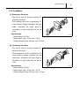
5.18 Compressor
(1) Compressor motor
• The CM 25 uses an inverter-controlled DC
compressor.
The
compressor
motor
is
operated by three-phase voltage outputted
from the STI module on the relay board.
Specifications:
- Rated Voltage: DC 220 V
- Rated Output: 1380 W
I003143
(2) Compressor overload relay
• An external compressor overload relay is used
Bimetal
to protect the compressor motor. This relay is
mounted within the connector housing that
attaches to the top of the compressor. The
Points
relay interrupts high temperature build-up in
the compressor.
Terminal
Specifications:
Temperature
Contact Open
248°F (120°C)
Contact Close
203°F (95°C)
I001691
Operation Section
41
5.19 Fan Motor
(1) Evaporator fan motor
• The CM 25 uses an inverter-controlled DC
evaporator fan motor.
• The evaporator fan motor is operated by DC
motor actuation voltage outputted by the relay
board.
Evaporator
fan
motor
speed
is
controlled by a relay board built into the fan
motor.
Specifications:
- Rated Voltage: DC 325 V
I003146
- Rated Output: High - 192 W, Low - 136 W
- Rotational Speed: High - 880 rpm, Low - 780 rpm
(2) Condenser fan motor
• The CM 25 uses an inverter-controlled DC
condenser fan motor.
• The condenser fan motor is operated by DC
motor actuation voltage outputted from the
relay board. Condenser fan motor speed is
controlled by a relay board built into the fan
motor.
Specifications:
- Rated Voltage: DC 325 V
- Rated Output: High - 322 W, Low - 187 W
- Rotational Speed: High - 865 rpm, Low - 710 rpm
I003147
Operation Section
42
5.20 Temperature Thermistor
• The
temperature
thermistor
detects
temperature as a resistance value.
I001695
Specification
Symbol
Denomination
Characteristic
RTS1
RTS2
CTS1
CTS2
CTS3
ODS
WMC room thermistor
Evaporator inlet air
thermistor
Condenser thermistor
Evaporator inlet pipe
thermistor
Evaporator outlet pipe
thermistor
Condenser inlet air
thermistor
Detect “SHORT”
Detect “OPEN”
8 k ohmat 77°F (25°C)
181°F (83°C) or higher
-29°F (-34°C) or less
5 k ohm at 77°F (25°C)
181°F (83°C) or higher
-29°F (-34°C) or less
5 k ohm at 77°F (25°C)
181°F (83°C) or higher
-29°F (-34°C) or less
5 k ohm at 77°F (25°C)
181°F (83°C) or higher
-29°F (-34°C) or less
5 k ohm at 77°F (25°C)
181°F (83°C) or higher
-29°F (-34°C) or less
5 k ohm at 77°F (25°C)
181°F (83°C) or higher
-29°F (-34°C) or less
5.21 Float Switch
• A normally closed float switch is installed in the
drain pan to prevent the drain pan from
overflowing and alerts the user of an abnormal
condition. When condensation in the drain pan
becomes full, the float rises and turning the
switch OFF. After the float switch is OFF for 60
seconds, the unit turns off, error code "PU" and
buzzer turn on.
I003151
Repair Section
43
6. TROUBLESHOOTING
WARNING
• Disconnect power supply from the unit before performing any service. Beware that some
residual voltages may remain in the unit immediately after the power is disconnected.
6.1 Troubleshooting
• Before troubleshooting the system, the following inspection should be performed.
(1) Inspection of power source voltage
• Check the voltage of the power source.
- Single-phase 208/230 V (60 Hz)
• Check the operation and condition of the fuse or circuit breaker in the power source.
(2) Inspection of air filters
• Remove the air filters and check the element. If the element is dirty, wash it as described in the
OPERATION MANUAL supplied with the unit.
Repair Section
44
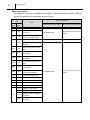
6.2 Self-Diagnostic Codes
• Self-diagnostic codes are displayed on the WMC and indicate by LED on the relay board under
the following conditions.
• LED on the relay board indicates self-diagnostic codes for the MWT under the following
conditions.
Self-Diagnostic
Code
Cause
User
Mode
Service
Mode
AL
AL
PU
PU
Fire alarm input
Condensation overflow
(Internal drain pump)
Relay Board
LED (Red)
Alarm
Pattern
1
1
2
3
3
4
5
6
Warning
Signal
Output
When receiving fire alarm
signal input.
ON
Condensation overflow
E07
E07
(Optional condensate
3
OFF
detected
HP
protection activated
E01
E01
E02
E02
E03
E03
When high-pressure switch is
activated 3-7 times in 24
hours from first detection.
4
WMC room thermistor
(RTS1) failure
Evaporator inlet air
thermistor (RTS2) failure
Condenser inlet air
thermistor (ODS) failure
E04
E05
E05
E06
E06
E08
E08
Condenser thermistor
(CTS1) failure
Evaporator pipe inlet
thermistor (CTS2) failure
Evaporator pipe outlet
thermistor (CTS3) failure
WMC communication
error
4
When high-pressure switch is
OFF eight times.
2
E04
When high-pressure switch is
activated 2 times in 24 hours
from first detection.
-
HP
High-pressure
When drain pan float switch
is OFF continuously for 60
seconds.
When optional drain pan float
switch is OFF continuously
for 60 seconds.
pump)
High-pressure signal
Detection Contents
ON
When an abnormality is
detected.
When a communication error
between the relay board and
WMC continues for at least
10 seconds.
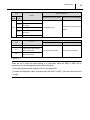
Repair Section
Self-Diagnostic
Code
Cause
User
Mode
Service
Mode
E09
E09
E10
E10
OL
OL
E11
E11
E14
E15
Relay Board
LED (Red)
Alarm
Pattern
1
2
3
4
Evaporator fan motor
5
6
Warning
Signal
Output
Condenser fan motor
locked
Compressor overload
STI module
When compressor overload
relay is activated.
When a communication failure
between the STI module and
microcomputer on the relay
board is detected for at least 40
seconds.
When compressor current is
detected at or above 35.9 A.
During the operational check
when the compressor is
stopped, no change in position
is detected.
When one phase is detected
as 0 A.
communication error
Compressor over
current
Compressor lock
failure
E12
E16
E17
E18
Compressor phase
interruption abnormality
Motor position
detection abnormality
E13
E21
E22
DC voltage
abnormality
Power device damage
abnormality
Circuit malfunction
When STI module input
current that exceeds the
specified value is detected.
When STI module
temperature that exceeds the
specified value is detected.
When a DC voltage or
current that is at or below the
specified value, or at or
above the specified value is
detected.
When a compressor startup
current/voltage that is at or
below the specified value is
detected.
When a short or open in the
STI internal current/voltage
detection circuit is detected.
abnormality
E20
When an abnormality in the
compressor motor position is
detected.
ON
Input overcurrent
temperature
4
Power device
E19
Detection Contents
When a fan motor speed of
50 rpm or less is detected
four times within 10 seconds
after the fan motor is started.
locked
45
46
Repair Section
Self-Diagnostic
Code
DF*1
Cause
Relay Board
LED (Red)
Alarm
Pattern
1
Freezing abnormality
-
2
3
4
5
6
Warning
Signal
Output
OFF
Detection Contents
When an evaporator inlet air
thermistor temperature at or
below 26.5°F (-3°C) is
detected during compressor
operation.
However, detection is not
possible for 5 minutes after
the compressor starts.
Evaporator fan motor
IR*1
reverse rotation
-
When a fan motor reverse
rotation signal (-760 rpm) is
detected.
abnormality
Condenser fan motor
OR*1
reverse rotation
-
abnormality
:
LED turn on
< NOTE >
*1 Shown with the operational status display mode.
When the fan is under the initial settings or in test mode, either the WMC or MWT will be
inoperative, and no self-diagnostic codes will be displayed.
• Verify self-diagnostic codes using the LED on the relay board.
• To erase self-diagnostic codes, (including either the WMC or MWT), open and close the circuit
breaker.
Repair Section
47
Alarm (buzzer) patterns
Pattern 1
Pattern 2
Pattern 3
Pattern 4
ON
OFF
ON
OFF
ON
OFF
ON
OFF
0.5 sec
1 sec
4 sec
I003173
Repair Section
48
Alarm clear method
• Self-diagnostic codes are not displayed for the MWT. To identify the cause, check the LED on
the relay board and refer to the charts on page 44 to 46.
Self-Diagnostic
Code
Alarm Clear Method
Cause
User
Mode
Service
Mode
AL
AL
PU
PU
E07
E07
Wall Mounted Controller (WMC)
Fire alarm input
Condensation overflow (Internal
drain pump)
HP
Press RESET button.
Reset the power from the circuit
breaker.
Condensation overflow
(Optional condensate pump)
High-pressure signal detected
HP
Millivolt Wall Thermostat (MWT)
Alarm clears automatically.
Alarm clears automatically.
High-pressure protection
activated
WMC room thermistor (RTS1)
E01
E01
E02
E02
E03
E03
E04
E04
E05
E05
E06
E06
E08
E08
WMC communication error
E09
E09
Evaporator fan motor locked
E10
E10
Condenser fan motor locked
OL
OL
Compressor overload
E11
E11
STI module communication error
E14
Compressor over current
E15
Compressor lock failure
E12
E16
E17
failure
Evaporator inlet air thermistor
(RTS2) failure
Condenser inlet air thermistor
(ODS) failure
Condenser thermistor (CTS1)
failure
Evaporator pipe inlet thermistor
(CTS2) failure
Evaporator pipe outlet
thermistor (CTS3) failure
Compressor phase interruption
abnormality
Motor position detection
abnormality
Press RESET button.
Reset the power from the circuit
breaker.
Repair Section
Self-Diagnostic
Code
49
Alarm Clear Method
Cause
User
Mode
Service
Mode
E18
E19
E20
E13
E21
E22
Self-Diagnostic
Code
DF*1
IR*1
OR*1
Wall Mounted Controller (WMC)
Millivolt Wall Thermostat (MWT)
Input overcurrent
Power device temperature
abnormality
DC voltage abnormality
Reset the power from the circuit
Press RESET button.
breaker.
Power device damage
abnormality
Circuit malfunction
Alarm Clear Method
Cause
Wall Mounted Controller (WMC)
Millivolt Wall Thermostat (MWT)
Alarm clears automatically.
Alarm clears automatically.
Freezing abnormality
Evaporator fan motor reverse
rotation abnormality
Condenser fan motor reverse
rotation abnormality
< NOTE >
*1 Shown with the operational status display mode.
When the fan is under the initial settings or in test mode, either the WMC or MWT will be
inoperative, and no self-diagnostic codes will be displayed.
• Verify self-diagnostic codes using the LED on the relay board.
• To erase self-diagnostic codes, (including either the WMC or MWT), open and close the circuit
breaker.
50
Repair Section
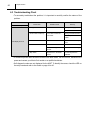
6.3 Troubleshooting Chart
• To accurately troubleshoot the problem, it is important to carefully confirm the nature of the
problem.
Condition
Check Area
Possible Cause
Remedy
Unit does not operate.
1. Voltage
Power failure.
Repair power supply.
Turn the circuit breaker on.
2. Ground fault breaker trip
Ground fault or defective
Repair ground fault section.
ground fault.
Reset or repair circuit
breaker.
LCD display turns off.
3. Fuse
Fuse is blown.
Replace fuse on the relay
board.
4. WMC/MWT
Incorrect connection.
Connect the wires correctly.
DIP switch setting is
Correct DIP switch setting.
incorrect.
5. Stop switch
Stop switch is in the STOP
Turn the stop switch to
position.
OPERATE.
• If conditions persist after the above actions have been taken, turn the unit off, disconnect the
power and contact your MovinCool reseller or a qualified technician.
• Self-diagnostic codes are not displayed for the MWT. To identify the cause, check the LED on
the relay board and refer to the charts on page 44 to 46.
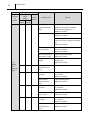
Repair Section
Condition
Unit does
not
operate.
51
Check Area
Self-Diagnostic
Codes
(WMC)
User
Mode
AL
Buzzer
Pattern
Possible Cause
Remedy
Service
Mode
AL
1
Signal is input from the
Check the fire alarm system and confirm
fire alarm.
there is no signal input to the unit, then
RESET the controller*1.
PU
PU
3
Drain hose clogged
Remove any blockage or excessive kinks
(for internal drain pump).
preventing water flow.
Drain hose trap position
Improve hose installation.
is too high to pump up
(Refer to the operation manual of this unit.)
condensation water
Drain water through the gravitational drain
(for internal drain pump).
pipe.
RESET the controller*1.
Internal drain pump is not
Reconnect the internal drain pump and
working.
check connection.
Drain water through the gravitational drain
LCD
pipe.
displays
RESET the controller*1.
self-
If the internal drain pump still does not work,
diagnostic
replace it.
codes.
E07
E07
3
Drain hose is clogged (for
Remove any blockage or excessive kinks
optional condensate
preventing air flow.
pump).
RESET the controller*1.
Drain hose trap position
Improve hose installation.
is too high to pump up
(Refer to the installation manual of the
condensation water (for
optional condensate pump.)
optional condensate
RESET the controller*1.
pump).
Optional condensate
Reconnect the drain pump and check the
pump is not working.
connection.
RESET the controller*1.
If the optional condensate pump still does not
work, replace it.
*1 : To RESET the controller, press RESET button, then press ON/OFF button.
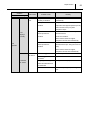
Repair Section
52
Condition
Unit does
not
operate.
Check Area
Self-Diagnostic
Codes
(WMC)
User
Mode
HP
Buzzer
Pattern
Possible Cause
Remedy
Service
Mode
HP
4
Operating outside of the
Check environmental condition. Do not
operating temperature
operate the unit outside the operating
range.
condition range. (See page 9.)
RESET the controller*1.
Insufficient air volume.
Clean air filter.
RESET the controller*1.
Check ducting of intake and exhaust air, and
make sure there are no objects preventing air
flow.
RESET the controller*1.
Loose high-pressure
Reconnect the high-pressure switch and
switch connection.
check the connection.
RESET the controller*1.
Defective high-pressure
Replace high-pressure switch.
switch (short or open).
RESET the controller*1.
Refrigerant is over
Charge correct amount of refrigerant.
charged.
(See page 86.)
LCD
displays
self-
RESET the controller*1.
E01
E01
2
Defective RTS1
Replace the WMC.
thermistor (short or
diagnostic
open).
codes.
E02
E02
2
Loose RTS2 thermistor
Reconnect the RTS2 thermistor and check
connection.
the connection.
RESET the controller*1.
Defective RTS2
Replace RTS2 thermistor.
thermistor (short or
RESET the controller*1.
open).
E03
E03
2
Loose ODS thermistor
Reconnect the ODS thermistor and check
connection.
the connection.
RESET the controller*1.
E04
E04
2
Defective ODS thermistor
Replace ODS thermistor.
(short or open).
RESET the controller*1.
Loose CTS1 thermistor
Reconnect the CTS1 thermistor and check
connection.
the connection.
RESET the controller*1.
Defective CTS1
Replace CTS1 thermistor.
thermistor (short or
RESET the controller*1.
open).
*1 : To RESET the controller, press RESET button, then press ON/OFF button.
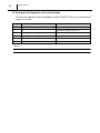
Repair Section
Condition
Unit does
not
operate.
53
Check Area
Self-Diagnostic
Codes
(WMC)
User
Mode
E05
Buzzer
Pattern
Possible Cause
Remedy
Service
Mode
E05
2
Loose CTS2 thermistor
Reconnect the CTS2 thermistor and check
connection.
the connection.
RESET the controller*1.
Defective CTS2
Replace CTS2 thermistor.
thermistor (short or
RESET the controller*1.
open).
E06
E06
2
Loose CTS3 thermistor
Reconnect the CTS3 thermistor and check
connection.
the connection.
RESET the controller*1.
Defective CTS3
Replace CTS3 thermistor.
thermistor (short or
RESET the controller*1.
open).
LCD
E08
E08
4
displays
self-
WMC lost communication
Check for connection or interference.
with the unit for more
RESET the controller*1.
than 10 seconds.
diagnostic
codes.
E09
E10
OL
E11
E09
E10
OL
E11
4
4
4
4
Evaporator fan motor is
Remove any foreign object causing fan lock.
locked.
RESET the controller*1.
Condenser fan motor is
Remove any foreign object causing fan lock.
locked.
RESET the controller*1.
Compressor overload
Repair the leaking section and recharge the
protection is activated by
correct amount of refrigerant.
refrigerant leakage.
RESET the controller*1.
Relay board
Check all wire connections on the relay
communication error
board.
occurs for 40 seconds.
RESET the controller*1.
If the error still occurs, replace the relay
board.
RESET the controller*1.
*1 : To RESET the controller, press RESET button, then press ON/OFF button.
Repair Section
54
Condition
Unit does
not
operate.
Check Area
Self-Diagnostic
Codes
(WMC)
User
Mode
E12
Possible Cause
Buzzer
Pattern
Remedy
Service
Mode
E14
4
Excessive current from
RESET the controller*1 twice or three times. If
the STI module to the
the error still occurs, replace the compressor.
compressor.
E15
4
Compressor lock.
RESET the controller*1 twice or three times. If
the error still occurs, replace the compressor.
E16
4
Compressor wires are
disconnected.
• Reconnect and check the compressor
wires.
• Reconnect and check the relay board
wires.
RESET the controller*1.
E17
4
Excessive compressor
RESET the controller*1 twice or three times. If
load.
the error still occurs, replace the compressor.
Excessive compressor
LCD
startup differential
displays
pressure.
Excessive current from
RESET the controller*1 twice or three times. If
diagnostic
the power source to the
the error still occurs, replace the compressor.
codes.
STI module.
self-
E13
E18
E19
E20
E21
E22
4
4
4
4
4
Degraded heat sink
Replace the relay board.
performance.
Then initialize the fan motor. (See page 61.)
Recovery from
Check if the supplied voltage to the unit is
momentary power loss or
unstable due to the external influence or not.
momentary voltage drop.
RESET the controller*1.
Momentary power loss,
If the error still occurs, replace the relay
or momentary voltage
board.
drop.
Then initialize the fan motor. (See page 61.)
Sensor on the relay board
Replace the relay board.
is short or open.
Then initialize the fan motor. (See page 61.)
Compressor actuating
Replace the relay board.
circuit on the relay board
Then initialize the fan motor. (See page 61.)
is short or open.
*1 : To RESET the controller, press RESET button, then press ON/OFF button.
Repair Section
55
Condition
Check Area
Possible Cause
Remedy
Insufficient Cooling
Air is not
Compressor start delay (120
Compressor starts after 120 seconds
cool.
seconds) is activated.
automatically.
Freeze protection is
Compressor starts automatically when
activated.
evaporator outlet pipe temperature (CTS3)
rises more than 43°F (6°C) while
compressor stops.
LCD
displays
normally.
Evaporator fan reverse
Fan rotates in reverse direction by
rotation protection is
abnormal air flow.
activated.
Check duct condition.
When reverse rotation is stopped,
compressor and fan start automatically.
Unit
Condenser fan reverse
Fan rotates in reverse direction by
operates.
rotation protection is
abnormal air flow (Ex. strong wind from out
activated.
side).
When reverse rotation is stopped,
compressor and fan start automatically.
Insufficient
Air filter is clogged.
Clean or replace air filter.
air volume
Leak or clogged on the duct
Repair duct connection.
connection.
Insufficient
Using longer duct length or
air volume
smaller duct diameter than
Change the duct to proper size.
recommended.
Fan is locked.
Check for any foreign object causing fan
lock.
56
Repair Section
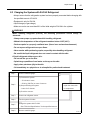
6.4 Self-Diagnostic Code Display Operation and Control
(1) WMC
• When an abnormality occurs in a unit, a selfdiagnostic code and “CHECK” will display on
the WMC.
Switching the self-diagnostic code display
mode
• The self-diagnostic code display can be
switched between user mode and service
Self-Diagnostic
Code
mode.
- Press and hold the “” and “” buttons
simultaneously for 3 seconds.
- When in the service mode, self-diagnostic
codes flash.
Self-diagnostic code reset
- While the self-diagnostic code is displayed,
"CHECK"
Turn On
press the “RESET” button.
I003174
The self-diagnostic code and “CHECK”
displays will turn off, and the system will switch to standby mode.
The LEDs on the WMC and relay board will illuminate.
(2) When the MWT is connected
• When an abnormality occurs in a unit, self-diagnostic codes are displayed via illuminated LEDs
on the relay board.
Self-diagnostic codes are reset by opening and then closing the circuit breaker.
LED 1~6
LED 7
1
6
Relay Board
ILL00686-00
Repair Section
57
6.5 Self-Diagnostic Code Records Display Operation
(Only When Connected With WMC)
• The unit power on time, compressor operation time, and self-diagnostic codes can be displayed
on the WMC when it is connected to CM 25. The unit power on time and compressor operating
time can be stored up to 65535 hours (automatically cleared to 0 hour and start counting). The
self-diagnostic codes can be stored up to 4 different codes.
(1) Display method
• To display the unit power on time, compressor operation time and self-diagnostic codes, set the
unit to standby mode, then press and hold the “RESET” button for 3 seconds.
• Unit power on time (Ot) is a default view. Press “” button to view the compressor operating
time (Ct) or press “” button to view the self-diagnostic code number 4. The view sequences
are shown in the figure below.
Ot (Total Unit Power On Time)
Ct (Compressor Operating Time)
Self-Diagnostic Code Display 1
Displayed Code
including "-- --"
Self-Diagnostic Code Display 2
Unit Power On Time/
Compressor Operation Time
Self-Diagnostic Code Display 3
Self-diagnostic Code
Display Number
Self-Diagnostic Code Display 4
*Displayed in reverse order using the "
" button.
ILL00531-01
Repair Section
58
(2) Exiting the self-diagnostic code records display
• To exit the self-diagnostic code records display, press the "RESET" button, or do not operate the
system for 1 minute.
Display No.
Display code
Function
-
Ot
Total unit power on time (unit: h)
-
Ct
Compressor operating time (unit: h)
1
Self-diagnostic code display
Self-diagnostic code record 1
2
Self-diagnostic code display
Self-diagnostic code record 2
3
Self-diagnostic code display
Self-diagnostic code record 3
4
Self-diagnostic code display
Self-diagnostic code record 4
< NOTE >
If there are no self-diagnostic codes, “-- --” will be displayed.
Repair Section
59
6.6 Operational Status Display Control
(Only When Connected With WMC)
• The operational status of each functional part can be displayed while the CM 25 is running.
(1) Display method
• Press and hold the “”, “”, and “FAN MODE” buttons simultaneously for 3 seconds.
• The display items can be switched using the “” or “” buttons.
(2) Exiting operational status display
• To exit the operational status display, press the “RESET” button, or do not operate the system
for 1 hour.
LCD Display
LED (Color : Green)
Displayed Code
Status Display
Control Panel
I003177
Repair Section
60
Displayed
Code
Display
Display Item
Display Example
Units
01
Compressor speed
rps
90 (90 rps)
02
Electronic expansion valve position
pulse
3 50 (350 pulse)
03
Evaporator fan motor speed
rpm
8 80 (880 rpm)
04
Condenser fan motor speed
rpm
8 65 (865 rpm)
05
Compressor operating current
A
15 (15 A)
06
Evaporator inlet air thermistor (RTS2)*1
°F/°C
80 (80°F)
07
Condenser inlet air thermistor (ODS)*1
°F/°C
95 (95°F)
°F/°C
120 (120°F)
°F/°C
104 (104°F)
08
Condenser thermistor
(CTS1)*1
(CTS2)*1
09
Evaporator pipe inlet thermistor
10
Evaporator pipe outlet thermistor (CTS3)*1
°F/°C
40 (40°F)
11
Self-diagnostic code
-
DF, IR, OR
< NOTE >
*1 Displayed in accordance with the WMC temperature unit setting.
Repair Section
61
6.7 Initialize Fan Motor
• Initialize the motor to correct the motor speed when any of the following components are
replaced: evaporator fan motor, condenser fan motor, relay board.
(1) Operation method
1) With the power supply OFF, turn DIP switch 2-1 ON.
2) Turn the power supply ON.
3) Turn DIP switch 3-1 ON.
The evaporator fan motor and condenser fan motor will stop after operating for approximately
one minute.
The LEDs on the relay board will illuminate in order while the fan motors are operating.
After the settings are complete, the fan motors will automatically stop, and all the LEDs on the
relay board will illuminate.
(2) Quit
4) Turn DIP switch 2-1 OFF.
5) Turn DIP switch 3-1 OFF.
6) The system will switch to standby mode.
< NOTE >
The WMC (or MWT) will be rendered inoperative.
• The initial settings are automatically determined to be satisfactory (OK) or unsatisfactory (NG).
When unsatisfactory, perform initialization again. If the settings are unsatisfactory after
initializing a second time, check the fan motors or relay board.
Judgment Value
Target speed ± 50 rpm
Display
OK
All relay board LEDs are illuminated.
NG
All relay board LEDs flash.
CAUTION
Perform initial settings after removing the evaporator inlet/outlet, and condenser inlet/outlet ducts
(unit-external static pressure = 0 Pa.)
Performing the initial settings with the ducts in place may result in an unsatisfactory (NG)
determination.
62
Repair Section
Initialize Fan Motor
TEST Mode
ON
OFF
1
2
DSW1
1
2
DSW2
1
2
3
DSW3
4
1
2
3
4
DSW4
I003178
Repair Section
63
6.8 TEST Mode
• Test operation can be performed using the test mode.
(1) Operation method
• Set the CM 25 to standby mode, turn DIP switch 3-1 ON, then turn on the unit. The unit will
automatically operate at the following conditions.
- Compressor speed: 90 rps
- Cool mode
- Fan mode: RUN
- Fan speed: HI
< NOTE >
The WMC (or MWT) will be rendered inoperative.
(2) Quit
• Turn DIP switch 3-1 OFF.
CM 25 operation will stop, and the system will shift to standby status.
TEST Mode
ON
OFF
1
2
DSW1
1
2
DSW2
1
2
3
DSW3
4
1
2
3
4
DSW4
I003179
64
Repair Section
6.9 Basic Inspection
• Perform the following inspection before disassembly.
(1) Inspection of plate fins
• To inspect the plate fins of either the
evaporator or condenser, the air filter must be
removed. After removal of the air filters, inspect
the plate fins for any dirt, dust, lint, or debris
that may have caused insufficient cooling
performance of the unit. If cleaning of the fins
is necessary, it is recommended that this
service be performed by a qualified service
I001780
technician.
(2) Examination of operating environment
• Operating environments can vary depending on location, climate and surrounding conditions.
Installation location also can cause operational problems. Consult your reseller concerning
operational environment requirements.
(3) Inspection of cooling capacity performance
• Measure
the
difference
in
temperature
between the inlet of the evaporator and the
cool air vent. If the difference is out of the range
Condenser Intake
Condenser
Exhaust
Insulated
Flexible Duct
given in the graphs on page 10, proceed with
the remedy suggested in the troubleshooting
chart on page 50 to 55.
Room
Air Intake
Cool Air Supply
(Evaporator)
Return Air Grill
With Filter Required
I003193
Repair Section
65
6.10 Inspection of Compressor
(1) Compressor motor
W
• Measure resistance across the terminals of the
compressor motor. (All terminals must be
disconnected from the unit.)
V
U
• Between terminals {at 68°F (20°C)}
- U-V Approx. 0.64 ohm
- V-W Approx. 0.64ohm
- W-U Approx. 0.64 ohm
I003180
• If the measured resistance is not equal to these
standard values, replace the compressor.
(2) Overload relay
• Check for continuity across two terminals of the
overload relay. At normal temperature, there
should be continuity across the terminals.
Specifications:
- OFF (Open contact): 248°F (120°C)
- ON (Closed circuit): 203°F (95°C)
• If there is no continuity across the terminals,
replace the overload relay.
I001701
Repair Section
6.11 Inspection of Electronic Expansion Valve Control Coil
• Measure resistance across the connector pins
of the electronic expansion valve control coil.
• Between connector pins {at 68 °F (20 °C)}
- Blue-Red Approx. 46 ohm
- Amber-Red Approx. 46 ohm
- Yellow-Red Approx. 46 ohm
- White-Red Approx. 46 ohm
• If the measured resistance is not equal to these
standard
values,
replace
the
electronic
expansion valve control coil.
Connector
Number
Wire
Color
1
2
3
4
5
Blue
Amber
Yellow
White
Red
1 2 3 4 5
I003194
6.12 Inspection of Thermistor
• Using an ohmmeter, check the resistance
• Thermistors:
- Evaporator inlet air thermistor (RTS2).
- Condenser inlet air thermistor (ODS).
- Condenser thermistor (CTS1).
- Evaporator pipe inlet thermistor (CTS2).
- Evaporator pipe outlet thermistor (CTS3).
Thermistor Specification
20
value across the 2-pin connector.
Resistance (k ohm)
66
15
10
5
0
32
(0)
41 50 59 68 77 86 95 104 133 122
(5) (10) (15) (20) (25) (30) (35) (40) (45) (50)
Temp.°F (°C)
I003204
6.13 Inspection of Wiring Connection
• Refer to the wiring diagrams on page 25, and check the connection of each wire.
CAUTION
Secure the wires using clamps to prevent contact with the edges of the structure, etc. Secure the
wires in the same position as prior to removal.
Repair Section
67
6.14 Inspection of Refrigeration System
• In most cases, the probable cause for insufficient cooling is a clog in the system, leakage or an
incorrect amount of refrigerant. In such cases, inspect the system according to the following
procedure.
(1) Clogged refrigeration system
• Check the component parts of the refrigeration system, including piping that could be clogged
with refrigerant. If clogged with refrigerant, only the clogged part is partially frosted. If this occurs,
replace the part in question.
(2) Refrigerant leak
• Carefully check all connections, and each component for leaks whenever the refrigeration
system is installed or repaired. Use an electronic gas leak tester to inspect the system. (See
page 78 to 87.)
(3) Insufficient refrigerant
• When the unit is not producing sufficient cooling, follow the troubleshooting chart on page 55 to
confirm the cause of the problem. Then, charge the system with the refrigerant to the specified
amount as indicated on page 86.
68
Repair Section
7. DISASSEMBLY
WARNING
• Disconnect power supply from the unit before performing any service. Beware that some
residual voltage may remain in the unit immediately after the power is disconnected.
7.1 Parts Construction
Rear Panel
Right Panel
Evaporator Inlet Air
Thermistor (RTS2)
Top Panel
Evaporator Pipe
Inlet Thermistor (CTS2)
Condenser
Thermistor (CTS1)
Condenser
Evaporator
Pipe Outlet
Thermistor (CTS3)
Evaporator
Frame
Evaporator Fan
Accumulator
Internal
Drain Pump
Compressor
Condenser Inlet Air
Thermistor (ODS)
Condenser Fan
Drain Pan
Float Switch
Left Panel
Frame
Control Box
Left Panel
Front Right Panel
Front Left Panel
Service Panel
ILL00667-00
Repair Section
69
7.2 Disassembly
1) Loosen the bottom screw.
Service Panel
2) Take out the nine (9) screws, and then remove
the service panel.
Screws (9)
Bottom Screw (1)
I003120
3) Disconnect the two (2) power supply lines from
the terminal, and disconnect the ground line.
Terminal
CAUTION
• Ground tightening torque:
Ground Line
- 1.0 ± 0.15 ft•lbf (1.3 ± 0.2 N•m)
Power Supply Line
I003182
4) Take out the twenty-eight (28) screws, and then
Top Panel
Screws (8)
Screws (4)
Screws (4)
Top Panel
Screws (12)
I003122
remove the top panel.
Repair Section
70
5) Take out the thirteen (13) screws, and then
remove the front right panel.
Screws (9)
Front Right Panel
Screws (4)
I003123
6) Take out the eleven (11) screws, and then
remove the front left panel.
Screws (4)
Screws (7)
Front Left Panel
I003124
7) Disconnect
the
two
(2)
connectors,
and
disconnect the ground line.
Connectors (2)
Ground Line
Pump
I003125
8) Take off the three (3) screws and bolt, and
Bolt (1)
remove the internal drain pump assembly.
Screws (3)
I003126
Repair Section
71
7.3 Removal of Evaporator Fan Assembly
Frame
Ring
Fan Motor
Set Screw
Frame
Fan
I003127
< NOTE >
Initialization is required after replacing the evaporator fan motor. (See page 61)
1) Take out the screw, and the four (4) nuts.
Screw (1)
Nuts (4)
Evaporator Fan
Assembly
I003128
2) Disconnect the motor connectors (white, 5-pin
Relay Board
and white, 4-pin) from relay board CN3, CN4,
and remove the evaporator fan assembly.
1
6
CN4
CN3
ILL00247-01
Repair Section
72
Set Screw
3) Take out the six (6) screws, and then remove the
ring. Loosen the set screw with an Allen wrench
Ring
Set Screw
and remove the fan.
Screws (6)
Fan
I003130
4) When assembling the fan, ensure that the screws
0.12 in (3 mm)
or more
0.12 in (3 mm)
or more
align with the motor axis positioning holes.
CAUTION
Set Screw
• Tightening torque:
- 10.0 ± 1.0 ft•lbf (14.0 ± 1.4 N•m)
• Verify the clearance between the fan and case
Motor Axis
I003131
ring. After installing the fan and fan motor,
ensure that the clearance between the fan and
case ring is at least 0.12 inch (3 mm).
5) Take out the four (4) nuts, and then remove the
motor stay.
Nuts (4)
Motor Stay
I003132
6) Take out the four (4) bolts, and then remove the
Fan Motor
fan motor.
CAUTION
Bolts (4)
When assembling the motor, ensure that the
wire connection ends are facing down.
I003133
Repair Section
73
7.4 Removal of Condenser Fan Assembly
Frame
Ring
Ring
Set Screw
Motor
Fan
Frame
I003134
< NOTE >
Initialization is required after replacing the condenser fan motor. (See page 61)
1) Take off the six (6) nuts.
Nuts (2)
Nuts (2)
Nuts (2)
Condenser Fan
Assembly
I003135
2) Disconnect the motor connectors (white, 4-pin
Relay Board
and white, 6-pin) from relay board CN1, CN2,
and remove the condenser fan assembly.
1
6
CN2
CN1
ILL00685-00
Repair Section
74
Set Screw
Set Screw
3) Take out the six (6) screws, and then remove the
ring. Loosen the set screw with an Allen wrench
and remove the fan.
Ring
Fan
Screws (6)
I003137
0.12 in (3 mm)
or more
0.12 in (3 mm)
or more
4) When assembling the fan, ensure that the screws
align with the motor axis positioning holes.
CAUTION
Set Screw
• Tightening torque:
- 10.0 ± 1.0 ft•lbf (14.0 ± 1.4 N•m)
• Verify the clearance between the fan and case
Motor Axis
I003138
ring. After installing the fan and fan motor,
ensure that the clearance between the fan and
case ring is at least 0.12 inch (3 mm).
5) Take out the four (4) nuts, and then remove the
motor stay.
Nuts (4)
Motor Stay
I003139
6) Take out the four (4) bolts, and then remove the
Fan Motor
fan motor.
CAUTION
Bolts (4)
When assembling the motor, ensure that the
wire connection ends are facing down.
I003140
Repair Section
75
7.5 Removal of Electrical Components
Box
Relay Board and
Bracket Assembly
Ground Bolt
Stop Switch
Terminal Block 1
Inductor Coil
Noise Filter
Terminal Block 2
Ground Bolt
Stay
I003202
76
Repair Section
(1) Relay board
to Compressor
Overlord Relay
to Wall Mounted
Controller
to High-Pressure
Switch
to Electronic
Expansion Valve
to Millivolt
Thermostat
to Float
Switch
to Stop
Switch
DIP Switch
to Evaporator Pipe
Inlet Thermistor and
Evaporator Outlet
to Evaporator Thermistor
Inlet Air
Thermistor
to Condenser
Thermistor
CN12
CN13
CN14
CN11
CN10
CN9
CN8
CN7
CN6
CN5
CN21
CN19
CN20
CN17
LED 7
LED1
LED2
LED3
LED4
LED5
LED6
to Output Signal
CN18
to Internal
Drain Pump Motor
to Condenser
Inlet Air
Thermistor (ODS)
LED 1~6
CN3
CN1
CN102
CN101
CN103
CN104
CN105
CN106
CN107
CN2
CN4
to Evaporator
Fan Motor
to Condenser
Fan Motor
to Evaporator
Fan Motor
to Condenser
Fan Motor
to Inductor Coil
Tighten Together
to Noise Filter
to Compressor
Ground Line
ILL00662-00
WARNING
• Do not touch the relay board until the green LED7 is turned off. Failure to follow this
warning may lead to electrical shock.
Removal of Relay Board
1) Disconnect the power at the source.
2) Loosen the bottom screw. (See page 69.)
3) Take out the nine (9) screws, and then remove the service panel. (See page 69.)
4) Disconnect all connectors from the relay board (18 connectors, 7 connections on the relay).
Refer to the figure “Relay board” to identify the relay connections and the connectors marked as
CN##. (To ensure easy reinstallation, be sure to label each connector wire as you remove them)
5) Take out the six (6) screws, and remove the relay board. The ground line for the relay board is
tightened together with the bottom right screw. (As shown in the illustration above, the relay
board and bracket assembly are replaced as a set.)
Repair Section
77
Replacement of Relay Board
1) Attach the relay board with the six (6) screws. Always tighten the ground line for the relay board
together with the bottom right screw. Make sure that the DIP switches on the new relay board
are all set to the off position.
2) Reconnect all 25 connectors to the new relay board. Refer to the figure “Relay Board” to identify
the connectors that need to be connected.
3) Reconnect the power at the source and turn on the unit to verify the function and operation of
the unit. Turn off the unit.
- The initial setting for motor speed must be done if the relay board is replaced.
- When using the MWT, its settings are also required.
4) Initialize the fan motor. (See page 61).
5) Close the service panel and secure with the nine (9) screws.
6) Tighten the bottom screw.
Repair Section
8. REFRIGERATION SYSTEM REPAIR
WARNING
• Disconnect power supply from the unit before performing any service. Beware that some
residual voltages may remain in the unit immediately after the power is disconnected.
8.1 Repair of Refrigeration System
• In case there is a leak, obstruction, or trouble in the refrigeration system, replace or repair the
part in question. After replacing any component all connections must be brazed.
(1) Proper brazing techniques
• It is desirable to use a slightly reduced flame. Oxyacetylene is commonly used since it is easy
to judge and adjust the condition of the flame. Unlike gas welding, a secondary flame is used for
brazing. It is necessary to preheat the base metal properly depending on the shape, size or
thermal conductivity of the brazed fitting.
• The most important point in flame brazing is to bring the whole brazed fitting to a proper brazing
temperature. Care should be taken to not cause overflow of brazing filler metal, oxidation of
brazing filler metal, or deterioration due to the overheating of flux.
(2) Brazed fittings and fitting clearance
• In general, the strength of brazing filler metal is
lower than that of the base metal. So, the
a
shape and clearance of the brazed fitting are
Clearance
0.001~0.003 in
(0.025~0.075 mm)
quite important. As for the shape of the brazed
fitting, it is necessary to maximize its adhesive
a
78
area. The clearance of the brazed fitting must
be minimized to facilitate brazing filler metal to
flow into it by capillary action.
Clearance From The Pipe Fitting and Tubing.
I002225
Repair Section
79
(3) Cleaning brazing filler metal and pipe
• When the refrigeration system has been opened up, exposure to heat may have caused brazing
filler metal to stick to the inside and outside of the pipe. Brazing filler metal may also be
compounded with oxygen in the air to form oxide film. Fats and oils may stick to the pipe from
handling. All these factors can reduce the effectiveness of brazing. It is necessary to eliminate
excess brazing filler metal using sand paper, and by cleaning thoroughly with a solvent such as
Trichlene.
CAUTION
Do not use chlorine cleaner.
(4) Use of dry nitrogen gas
• During brazing, the inside of the pipe undergoes an oxidative reaction due to the brazing flame.
Introduce dry nitrogen gas {0.3 gal/min (1 L/min)}; adjust with the flow regulator} through the
pinch-off tube of the refrigerant.
< NOTE >
Take care not to allow dirt, water, oil, etc. to enter into the pipe.
(5) Vertical joints
• Heat the whole brazed fitting to a proper
brazing temperature. Bring the brazing filler
45°
metal into contact with the fitting so that the
Vertical Down Joint
Brazing Filler Metal
Burner
brazing filler metal starts flowing by itself.
• Stop heating the fitting as soon as the brazing
filler metal has flown into the clearance. Since
the brazing filler metal flows easily into portions
heated to the proper temperature, it is essential
Tube
I000564
to keep the whole fitting at the proper brazing
temperature.
Vertical Up Joint
Tube
Burner
45°
Brazing Filler Metal
I001725
Repair Section
80
8.2 Removal of Refrigeration System Components
WARNING
• Before replacing any refrigeration cycle component, recover the refrigerant using
standard recovery procedures and equipment.
• When recovering the refrigerant, use the pinch-off tubes at the low pressure side (tube 1)
and high pressure side (tube 2) as shown in the figure below.
CAUTION
• To prevent oxidation, dry nitrogen should be conducted {flow rate 0.27 gal/min (1 L/min)} through
the pinch-off tube during any brazing operation.
• During any component replacement involving brazing, shield nearby parts with a steel plate, etc.,
to protect them from the flame.
Tube 2
H
Part to Replace
• Compressor
• Condenser
• Electronic Expansion Valve
• Evaporator
• High Pressure Switch
E
D
Disconnect at
A, I
B, C
C, D
E, F, G, H
J
C
Tube 1
F
B
Pipe 1
J
I
G
A
Pipe 2
ILL00668-00
< NOTE >
When replacing the compressor, attach the pipe 1 and the pipe 2 packaged in the compressor
assembly.
Repair Section
81
8.3 Charging the System with R-410A Refrigerant
• Always ensure that the refrigeration system has been properly evacuated before charging with
the specified amount of R-410A.
• Equipment is only for R-410A.
• Liquid charge (no gas charge).
• Make sure not to use more than 90% of the initial weight of R-410A in the cylinder.
WARNING
• When handling refrigerant (R-410A), the following precautions should always be
observed:
- Always wear proper eye protection while handling refrigerant.
- Maintain the temperature of the refrigerant container below 104°F (40°C).
- Perform repairs in a properly ventilated area. (Never in an enclosed environment.)
- Do not expose refrigerant to an open flame.
- Never smoke while performing repairs, especially when handling refrigerant.
- Be careful the liquid refrigerant does not come in contact with the skin.
• If liquid refrigerant strikes eye or skin:
- Do not rub the eye or the skin.
- Splash large quantities of cool water on the eye or the skin.
- Apply clean petroleum jelly to the skin.
- Go immediately to a physician or to a hospital for professional treatment.
Step 1
Connect manifold gauge.
1) Evacuate the system.
• 15 minutes or more.
Step 2
• 30 inHg (100 kPa) or more of vacuum.
2) Stop evacuating the system.
• Leave for 5 minutes.
When leak is found,
repair the connection
or components.
3) Check the vacuum.
Step 3
Connect to refrigerant source.
Step 4
Test the system for leaks.
Step 5
Step 6
Charge the system with R-410A.
• See “Technical Specifications” for the specified amount.
Remove manifold gauge.
ILL00084-00
82
Repair Section
(1) Connection of gauge manifold
1) Properly remove the crushed end of the pinch-off
Charging Hose
Side
Refrigerant
Cycle Side
tube at the high-pressure side and the low
pressure side of the refrigerant cycle with a pipe
cutter.
2) Fit the process tube fitting to the pinch-off tube on
both sides.
Seal
Pinch-Off Tube
I002183
3) Connect the charging hoses (red high-pressure
Low-Pressure
Valve (Closed)
High-Pressure Valve
(Closed)
Red Hose
Green Hose
Process Tube Fitting
High-Pressure
Side Tube
side) for the gauge manifold to the process tube
fitting.
< NOTE >
Connect the hoses using care not to mistake
the high-pressure side for the low-pressure
side and vice versa.
Vacuum Pump
(When Stopped)
I000568
4) Connect the charging hose (green) at the center
of the gauge manifold to the vacuum pump.
(2) Evacuation
1) Open the high-pressure valve (Hl) of the gauge
Valve Setting
Gauge
Low-Pressure
Valve
LO
HI
Closed Open
LO
HI
Closed Closed
30 inHg (100 k Pa) or larger
High-Pressure Gauge
High-Pressure Valve
manifold.
2) Turn on the vacuum pump to start evacuation.
(Evacuate the system for approximately 15
minutes.)
High-Pressure
Side Tube
Vacuum Pump
(in Operation)
3) When the high-pressure gauge indicates 30 inHg
(100 kPa) or higher, turn off the vacuum pump
I002227
and close the high-pressure valve of the gauge
manifold.
Repair Section
83
(3) Checking vacuum
Valve Setting
LO
HI
Closed Closed
Pressure Gauge
1) Leave the high-pressure valve and the lowLeave valves closed for 5
minutes or more. Pointer of
pressure gauge returning to
zero indicates there is a leak.
pressure valve of the gauge manifold closed for 5
minutes or more, and confirm that the gauge
pointer does not return to zero.
2) If the gauge pointer returns gradually to zero
Return
there is a leak somewhere in the system (this
Pipe Brazing
could also include gauge manifold). Perform a
I003203
leak check according to the procedure indicated
in the next step. Once the leak has been found
and repaired, evacuate the system once more to
confirm that the system holds vacuum.
Repair Section
(4) Checking for gas leaks
1) Remove the charging hose (green) from the
Valve Setting
vacuum pump, and connect the hose to the
LO
HI
Closed Closed
Air Purging
refrigerant cylinder (R-410A).
Charging Hose
Red
(Green)
to Process Tube Fitting
2) Loosen the nut on the gauge manifold side of the
Refrigerant
Cylinder R-410A
Open The Valve
of Refrigerant
Cylinder
charging hose (green).
3) Open the valve of the refrigerant cylinder and
perform air purging in the charging hose (green).
I001901
Low-Pressure
Valve (Closed)
Refrigerant
Cylinder
Valve
(Open)
Then tighten the nut.
4) Open the high-pressure valve of the gauge
Valve Setting
LO
HI
LO
HI
Closed Open Gauge Reading Closed Closed
Refrigerant
Cylinder R-410A
84
manifold. Charge the system with refrigerant until
57 psi
(390 k Pa)
the high-pressure gauge indicates 57 psi (390
Open High-Pressure
Valve
Process Tube Fitting
High-Pressure
Side Tube
I002228
kPa). After charging is complete, close the highpressure valve.
5) Open the valve of the refrigerant cylinder and
perform air purging in the charging hose (green).
Then tighten the nut.
6) Check carefully for gas leaks inside the
refrigerant system using the gas leak tester.
7) Repair any leak.
WARNING
Any repair on a charged system should be
performed by a licensed professional only.
WARNING
Before checking for gas leaks, fully confirm
that there is nothing flammable in the area
to cause an explosion or fire. Contact of
refrigerant with an open fire generates
toxic gas.
Repair Section
85
(5) Evacuation (repeat)
1) Close the valve of the refrigerant cylinder. Then
Valve Setting
Gauge
Low-Pressure
Valve
LO
HI
Closed Open
LO
HI
Closed Closed
30 inHg (100 k Pa) or larger
High-Pressure Gauge
High-Pressure Valve
High-Pressure
Side Tube
Vacuum Pump
(in Operation)
remove the charging hose (green) from the
refrigerant cylinder, and connect it to the
refrigerant recovery machine.
< NOTE >
Keep the high-pressure valve and the lowpressure valve of the gauge manifold closed.
I002227
2) Using
the
procedure
under
“Evacuation”,
evacuate the system until the high-pressure
gauge indicates 30 inHg (100 kPa) or larger. (For
15 minutes or more.)
3) After evacuation is complete, close the high and
the low pressure valves of the gauge manifold.
CAUTION
Make sure to evacuate the system twice or
more using the repetitive vacuum method.
Evacuate the system an additional time on
rainy or humid days.
Repair Section
8.4 Refrigerant Charging Work
(1) Refrigerant charging
1) Remove the charging hose (green) from the
Valve Setting
vacuum pump, and connect it to the refrigerant
LO
HI
Closed Closed
Air Purging
cylinder (R-410A).
Charging Hose
Red
(Green)
to Process Tube Fitting
2) Loosen the nut on the gauge manifold side of the
Refrigerant
Cylinder R-410A
Open The Valve
of Refrigerant
Cylinder
charging hose (green). Open the valve of the
charging hose (green). Open the valve of the
refrigerant cylinder. After air purging, tighten the
I001901
nut and close the valve of the refrigerant cylinder.
3) Securely place the refrigerant cylinder on a scale
Valve Setting
LO
HI Specified Amount
LO
HI
Closed Open
Closed Closed
of Refrigerant
with a weighing capacity of 70 lb (30 kg) that is
graduated in 0.2 oz (5 g) increments.
High-Pressure Valve
Valve of
Refrigerant
Cylinder
Process Tube Fitting
Refrigerant
Cylinder R-410A
86
High-Pressure
Side Tube
Weight
I001903
4) Open the high-pressure valve of the gauge
manifold and the valve of the refrigerant cylinder.
Charge the system with refrigerant to the
specified amount.
Standard Amount of Refrigerant: 2.31 lb
(1.05 kg)
CAUTION
The amount of refrigerant charged has a great
effect on the cooling capacity of the unit.
Charge to the specified amount, always
observing
the
scale
graduations
while
charging.
5) Close the high-pressure valve of the gauge
manifold and the valve of the refrigerant cylinder.
Repair Section
87
(2) Removal of gauge manifold
1) Crimp the pinch-off tube with a pinch-off tool.
Pinch-Off Tool
Pinch-Off Tube
2) Remove the gauge manifold and the process
to Gauge
Manifold Side
tube fitting. Crush the end of the pinch-off tube.
3) Braze the end of the pinch-off tube.
Charging Hose
to Refrigerant
Cycle Side
4) Ensure that a gas leak is not present at the
pinched off portion and the brazed end.
Process Tube Fitting
I002185
88
Repair Section
9. REASSEMBLY
9.1 Reassembly of Unit
• Reassemble the unit in the reverse order of removal. Described below are the parts that require special
care in reassembling the unit. Perform all wiring or rewiring as referenced in the wiring diagram.
9.2 Compressor Mounting
• Mount the compressor on the frame, using
cushions, steel collars, plate washers, and
Nut
nuts.
Plate Washer
Cushion
Steel Collar
ILL00178-00
9.3 Evaporator Fan Assembly
• Install the evaporator fan. Allow a clearance of 0.12 inch (3.0 mm) or more on each side of the
evaporator fan. (See page 72.)
< NOTE >
Initialize the fan motor after replacement. (See page 61.)
9.4 Condenser Fan Assembly
• Install the condenser fan. Allow a clearance of 0.12 inch (3.0 mm) or more on each side of the
condenser fan. (See page 74.)
< NOTE >
Initialize the fan motor after replacement. (See page 61.)
9.5 Wiring Notice
• Secure the wires using clamps so that they do not come into contact with the edges of the
structure. Secure the wires using clamps in the same position they were before removal.
9.6 Perform an Inspection
• Perform an inspection of cooling performance and check for abnormal noise or vibration.
P/N: SV0075-01
Second Issue: January 2013