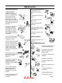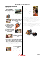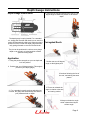
1
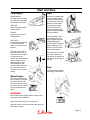
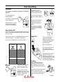
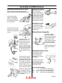
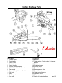
High Performance
Ventilation Chain Saws
3924 E. Trent Ave.
Spokane, WA 99202
(509)535-7746 (509)535-9064
1-800-745-3282
Contents
Congratulations....
CONTENTS
On your purchase of the worlds finest high
performance, ventilation saw. This saw has
been designed to meet the rugged requirements of the fire service. To ensure maximuim
performance and reliability this saw’s carburator
should be set for the altitude it is intended to
run at, and the R.P.M. should be set at 13,500.
This can be achieved through the dealer you
purchased the saw from or at any authorized
Unifire dealer. If you should need assistance in
locating the nearest dealer please call 1-800745-3282 and ask for our customer service
deptartment. We would sincerely like to thank
you for your purchase of Unifire’s ventilation
saw, one of the team products.
Safety Instructions
Personal protective equipment
General Safety precations
Avoiding Kickback
Cutting Equipment
Before Using A New Saw
Start and Stop
Procedures and hints
Read the instructions carefully.
Check all cutting equipment is all correctly fitted and
adjusted.
Refuel and start the saw. Check carburetor settings.
Do not use the saw until sufficient chain oil has
reached the chain.
WARNING!
Under no circumstances may the design of the
machine be modified without the permission of
the manufacturer. Always use genuine spare
parts/accessories. Non Autorized modifications
and/or accessories can result in serious personl
injury or the death of the operator or others.
The warranty does not cover damage or liability
caused by the non-authorized accessories or
replacement parts.
WARNING!
The engine exhaust from this product contains
chemicals known to the state of California to
cause cancer, birth defects or other reproductive
harm.
The warranty does not cover damage or liability
caused by the non-authorized accessories or
replacement parts.
What is What
Saw parts diagram
Assembly
Mounting guide bar and chain
Fuel Handling
Fuel mix
Fueling
Maintenance
Air Filter
Spark Plug
Tensioning the recoil spring
Changing recoil spring
Carburetor
Daily maintenace
Weekly maintenance
Monthly maintenance
Depth Guage Instructions
3924 E. Trent Ave.
Spokane, WA 99202
Phone: (509)535-7746
Fax: (509)535-9064
1-800-745-3282
www.unifireusa.com
Page 1
Start and Stop
Cold Engine
Start
CHAIN BRAKE:
Disengage the cain brake
by pulling the hand gaurd
towards the front handle.
Grip the front handle with
your left hand and hold
the saw down by putting
your right foot in the rear
handle. Pull the starter
handle with your right
hand and pull out the
starter cord slowly until
the starter pawls engage.
Then pull sharply.
IGNITION:
Move the ignition switch
to start position
CHOKE:
Set the choke control in
choke position.
FAST IDLE:
Combined choke/fast idle
is received when the
choke is moved to choke
position.
This saw is fitted with a
decompression valve (A):
Press the valve to reduce
the pressure in the
cylinder and make starting
easier. Always use the
decompression valve
when starting the saw.
Once the saw has started
the valve will automatically return to its original
setting.
Push the choke control
immediately when the
engine ignites and make
repeated starting attempts. When the engine
starts, rapidly give full
throttle. Then the trottle
latch will disengage.
CAUTION! Do not release
the starter handle from
fully pulled out position as
this can cause damage to
the saw.
Stop
The engine is stopped by
switching off the ignition.
Warm Engine
Use the same procedure
as for starting cold engine
but without choke. Fast
idle is received by first set
the choke control in choke
position, and then back
again.
WARNING!
Never start the saw engine without the bar, chain
and clutch cover assembled.
Always move saw away from fueling area.
Place the saw on clear ground, and make sure you
have secure footing
Page 2
Fuel Handling
Gasoline
This engine is ceritified to operate on unleaded
gasoline.
Mix (shake) the fuel
mixture thoroughly before
filling the saw’s fuel tank.
Do not mix more than the
max one months supply of
fuel.
Use good quaility unleaded gasoline.
The lowest recommended
octane rating is 87.
If the saw is not used for
sometime the fuel tank
should be emptied and
cleaned.
When working at continuous high revs a higher
octane is recommended.
This engine is certified
to operate on unleaded
gasoline.
Two-stroke Oil
For the best results use HUSQVARNA two-stroke oil,
which is especially developed for chain saws. Mixing
ratio 1:50 (2%).
Never use two stroke oil intended for water cooled
outboard engines, or so-called outboard oil.
Chain Oil
Never use oil intended for four stroke engines.
The chain lubrication
system is automatic.
Always use special chain
oil with good adhesive
characteristics.
Never use waste oil!
Lit.
5
10
20
US
GALLON
US
fl. oz.
1
2 1/2
6 1/2
1 1/2
5
Mixing
Lit.
0, 10
0, 20
0, 30
0, 40
15
It is important that the oil
is the right viscosity
according to air temperature.
Fueling
In temperatures below 0
degrees C some oils
become too viscous. This
can overload the oil pump
and result in damage to
the oil pump components.
Always mix the gasoline
and oil in a clean container intended for fuel.
Clean around the fuel cap.
Clean the fuel and chain oil
tanks regularly. The fuel filter
should be changed at least once
a year.
Start by filling half the
gasoline to be used. Then
add the entire amount of
oil. Mix. (shake) Add
remaining gas.
The volume of chain oil and fuel
tanks are adjusted to each
other. Therefore, always fill the
chain oil and fuel at the same
time.
12 7/8
Page 3
Assembly and Maintenance
Mounting Guide Bar and Chain
Always wear gloves when working with the
chain, in order to protect your hands from injury!
Check that the chain
brake is in disengaged
position by moving the
front hand guard towards
the front handle.
Hold up the tip of the bar
and tighten the chain. The
chain is correctly
tensioned when there is
no slack on the underside
of the bar, but it can still
be turned easily by hand.
Hold up the bar tip and
tighten the bar nuts with
the combination wrench.
When fitting a new chain
the chain tension has to
be checked frequently
until it is run-in. And then
check the tension on a
regular basis.
Take off the bar nuts and
remove the clutch cover.
Take off the transportation
ring (A).
Starter Device Assembly
Fit the bar over the bolts.
Place the bar in its
rearmost position. Place
the chain over the drive
sprocket and in the
groove on the bar. Begin
on the top side of the bar.
Make sure that the edges
on the cutting links are
facing forward on the top
side.
Fit the clutch cover and
locate the chain adjuster
pin in the hole on the bar.
Check that the drive links
of the chain fit correctly
on the drive sprocket and
that the chain is in the
groove on the bar. Tighten
the bar nuts finger tight.
Tension the chain by using
the combination wrench.
Turn clockwise. The chain
should be tensioned until
it fits snugly.
Assemble the starter
device, by pulling the
starter cord out first, then
place the starter against
the crankcase. Then
slowly release the starter
cord so that the pulley
engages with the pawls.
Assemble and tighten the
screws, which hold the
starter
Adjustment of oil pump
The oil pump is adjustable. Adjustments are
made by turning the
screwdriver or combination spanner.
Turning the screw clockwise will reduce the oil
flow and turning the screw
anti-clockwise will increase the oil flow.
Recommended settings:
Bar
Bar
Bar
Bar
-15”:1 turn from the closed position
15”-18”: 2 turns from the closed position
18”-24”: 3 turns from the closed position
24”- :4 turns from the closed position
Page 4
Maintenance
3 Stage Air Filtration
Changing a broken starter cord
The air filter must be regularly cleaned from
dust and dirt in order to avoid:
- Carburetor malfunctions
- Starting problems
- Engine power reduction
- Unnecessary wear on
engine parts
- Abnormal fuel consumption
Loosen the screws, that hold
the device against the crankcase and remove the starter
device
Clean the air filter daily or
more often if the air is
exceptionally dusty in the
working area.
Disassemble the air filter by
removing the air filter cover
and unscrew the filter. When
reassembling, make sure that
the filter is tight against the
filter holder.
Pull out the cord approx. 30
cm and lift it up into the notch
in the pulley. Zero-set the
recoil spring by letting the
pulley rotate slowly backwards. Undo the screw in the
centre of the pulley and
remove the pulley.
A more thorough cleaning of
the filter is obtained by
washing it with soap and
water.
Insert and fasten a new starter
cord in the pulley. Wind
approx. 3 turns of the starter
cord on to the pulley. Assemble the starter pulley
against the recoil spring,
sothe end of the spring
engages to the pulley. Fit the
screw in the center of the the
pulley. Carry the starter cord
through the hole in the starter
housing and the starter
handle. Make a knot on the
starter cord.
Spark Plug
Tensioning the recoil spring
Clean the filter by brushing or
shaking it.
The spark plug condition is influenced by:
- An incorrect carburetor setting
- Wrong fuel mixture (to much oil in gasoline)
- A dirty air filter
If the engine is low on
power, difficult to start or
runs poorly at idling speed,
always check the spark plug
first.
If the spark plug is dirty, clean
it and check electrode gap.
Readjust if necessary. The
correct gap is 0,5 mm (0,
020”) The spark plug should
be replaced after about a
month in operation or earlier if
the electrodes are badly
eroded.
Lift the sarter cord up in the
notch on the starter pulley
and turn the starter pulley 2
turns clockwise.
NOTE! Check that the
starter pulley can be turned
at least half a turn, when the
starter cord is entirely pulled
out.
Changing the broken recoil spring
Lift starter pulley
Dissasemble the recoil spring by tapping the
pulley lightly against a working bench. If the
spring pops out when assembling it should be
mounted again, out and in the center.
Lubricate the recoil spring with thin oil. Assemble the starter pulley, and tension the
recoil spring.
Page 5
Maintenance
Carburetor
Low speed needle L
The Unifire Pro-Saw has
been designed and
manufactured to specifications that reduce
harmful emissions. After
your unit has been run 810 tanks of fuel the engine
has broken in. To ensure
that your unit is at peak
performance and producing the least amount of
harmful emissions after
break in, adjust your
carburetor for optimum
operating conditions.
Turn the low speed needle L
clockwise until the stop. If the
engine has bad acceleration or
erratic idling, turn the L needle
counter-clockwise until good
idling and acceleration.
Final setting for the idling speed T
Adjust the idling speed with the screw T. If it is
necessary to re-adjust, first turn the idle speed
adjusting screw T clockwise, until the chain starts to
rotate. Then turn, counter-clockwise until the chain
stops. A correctly adjusted idle speed setting occurs
when the engine runs smoothly in every position. It
should also be good margin to the rpm when the
chain starts to rotate.
Operation
The carburetor governs the engines speed via the
throttle. Air/fuel are mixed in the carburetor. The air/
fuel mixture is adjustable. To take advantage of the
engines optimal output the setting must be correct.
The setting of the carburetor means that the engine
is adapted to local conditions, for example the
climate, altitude, fuel and the type of 2-stroke oil.
The carburetor has three
adjustment possibilities.
L: Low speed jet
H: High speed jet
T: Adjustment
screw for idling.
The fuel quantity required in relation to the air flow,
provided by opening the throttle, is adjusted by the L
and H jets. If they are screwed clockwise the air/fuel
ratio becomes leaner (less fuel) and if they are
turned counter clockwise the ratio becomes richer
(more fuel). A leaner mixture gives a higher engine
speed and a richer mixture give a lower engine
speed.
The T screw regulates the idling speed. If the screw
T is turned clockwise this gives a higher idling
speed; counter-clockwise a lower idling speed.
Fine Adjustment
When the saw has been “run-in” the carburetor
should be finely adjusted. The fine adjustment
should be carried out by a quailified person. First
adjust the L-jet, then the idling screw T and then the
H-jet.
High speed needle H
The high speed needle H
influences the power of the
saw. A too lean adjusted high
speed needle H (high speed
needle H closed too much)
gives overrevs and damages
the engine. Turn the high
speed needle H counter
clockwise until the stop. If
the engine runs roughly, turn
the high speed needle slowly
the miniumum amount
clockwise until the engine
runs smoothly.
The high speed needle H is correctly set when the
saw “4-cycles” a little. If the saw “whistles” the setting
is too lean. If there is too much exhaust gas at the
time as the saw ”4-cycles” much, the setting is too
rich. Turn the high speed needle H until the setting
sounds correct. NOTE! For optimum setting of the
carburetor, contact a quailified servicing dealer
who has a revolution counter at his disposal.
Correctly adjusted carburetor
A correctly adjusted carburetor means that the saw
accelerates without hesitation and the saw 4-cycles a
little at max speed. Furthermore, the chain must not
rotate idling. A too lean adjusted low speed needle L
may cause starting difficulties and bad acceleration.
A too lean adjusted high speed needle H gives lower
power-less capacity, bad acceleration and/or damage to the engine. A too rich adjustment of the two
speed needles L and H gives acceleration problems
or too low working speed.
Page 6
Maintenance
Daily Maintenance
Weekly Maintenance
1. Check the throttle
trigger for smooth
operation. If and binding
occurs, or if engine fails to
return to idle, the saw
should be taken to your
dealer before it is used
again. Also be sure that the
trigger cannot be pulled until
the throttle trigger lockout is
depressed.
1. Check that the AV
elements are not soft or
torn.
2. Clean the chain brake
and check its function
according to the instructions. Make sure that the
chain catcher is undamaged. Otherwise replace it
immediately.
3. Clean or replace the air
filter as necessary. Check
for damage or holes.
4. The bar should be turned
daily for more even wear.
Check the lubrication hole in
the bar, to be sure it is not
clogged. Clean the bar
groove, if the bar has a
sprocket tip, this should be
lubricated.
5. Check the function of the
oiler to be sure the bar and
chain receive proper
lubrication.
6. Sharpen the chain and
check its tension and
condition. Check the drive
sprocket for wear. Replace if
necessary.
7. Check the starter and
starter cord for wear or
damage. Clean the air
intake slots on the starter
housing.
8. Check for loose nuts and
screws and retighten if
necessary
2. Lubricate the clutch drum
bearing.
3. File off burrs, if any, on
the side bar.
4. Clean spark plug and
check gap.
5. Check the starter and the
recoil spring. Clean the fins
on the flywheel.
6. Clean the cooling fins on
the cylinder.
7. Clean or change the
screen in the muffler.
8. Clean the carburetor body
and air box.
Monthly Maintenance
1. Check the brake band on
the chain brake for wear.
2. Check the clutch centre,
clutch drum and clutch
spring for wear.
3. Clean the outside of the
carburetor.
4. Change the fuel filter.
5. Clean the inside of the
fuel tank.
6. Clean the inside of the oil
tank.
7. Check all cables and
connections.
8. Change the spark plug.
9. Change the air filter.
Page 7
Depth Guage Installation
Depth Guage Installation
Instructions
TOOLS REQUIRED:
1/2 inch wrench (or 13mm)
Loctite 272-(provided)
17/64 Drill Bit
Center Punch
6. Plunge the gauge
several times to check for
binding. Use a spray
lubrication such as WD 40
for easy sliding.
1. Remove the Bar from the
powerhead. Clean bar if it has
been used.
2. Mark the bar for hole positions
using the template provided. For
precise drilling use a center
punch.
3.. Replace the bar onto
the powerhead and install
chain. Adjust chain to
proper tension.
NOTE: SPRING TENSION MAY DECREASE
SOMEWHAT WITH EXTENSIVE USE. TO
RESTORE TENSION, REMOVE THE SPRING
AND STRETCH A COUPLE OF INCHES AND
THEN REPLACE SPRING.
WARNING: CHAIN TENSION MUST BE MONITORED DURING USE. IF THE CHAIN BECOMES LOOSE IT MAY CAUSE DAMAGE OR
INJURY.
4. Slide Depth Gauge over
bar and chain. Line Depth
Gauge studs up to holes in
bar and insert.
5. Apply Loctite 272
(provided) to Depth Gauge
studs.
NOTE: USE LOCTITE 272 (OR COMPARABLE)
ON ALL BOLTS AND NUTS ON THE DEPTH
GAUGE. LOCTITE 272 IS A HIGH STRENGTH
HEAT RESISTANT FASTENER ADHESIVE THAT
MAY REQUIRE HEATING THE AREA AROUND
THE FASTENER FOR REMOVAL.
6. Put stud nuts on and
tighten.
WARNING: Do not over
tighten Depth Gauge stud
nuts.
Page 8
Depth Guage Instructions
Depth Guage Instructions
The depth guage is spring loaded. For a standard
cut, simply push saw bar and chain into cut area, the
guage will automatically slide back. When the saw is
pulled out of the cut then the depth guage automatically springs forward to cover the bar and chain.
4. Once the cut has been started move saw to a 90
degree angle to achieve a precise cut at desired
depth.
Corrugated Roofs
The pin can be positioned in a hole to set a plunge
depth or can be set in a locked position to hold a
specified cutting depth.
Application
1. Using the positive stop pin set your cut depth and
lock into position.
1. Position saw at a 30 degree
angle, at the highest point.
2. Position saw at a 30 degree angle. (This angle is
preset on your depth guage.)
2.Continue following the line of
the roof, maintaining the same
pattern.
3. For a standard cut push saw bar and chain into
cut area, the guage will automatically slide back to
your predetermined cut depth.
3.Tilt saw to maintain the
angle in relation to the saw
and cutting surface.
3.Always maintain the angle
which is determined by the
surface angle.
Page 9
Unifire Pro-Saw Parts
What is it?
1. Cylinder cover
2. Front Handle
3. Starter Cover
4 Chain oil tank
5. Starter Handle
6. Adjuster screw, carburetor
7. Choke Control/Start throttle lock
8. Rear handle
9. Stop switch, Ignition on/off switch
10. Fuel tank
11. Muffler
12. Bar tip sprocket
13. Saw chain
15. Saw bar
16. Bumper
17. Chain catcher. Catches chain if it jumps or
breaks.
18. Clutch cover
19. Right hand guard.
20. Throttle control
21. Throttle Lock
22. Decompression valve
23. Combination spanner
24. Chain tensioning screw
25. Operators manual
26. Bar guard
Page 10
27. Switch for heated handles.