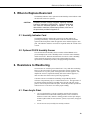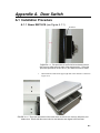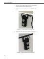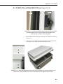
1
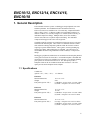
ENC10/12, ENC12/14,
ENC14/16, ENC16/18
Revision: 7/11
C o p y r i g h t © 2 0 0 6 - 2 0 1 1
C a m p b e l l S c i e n t i f i c , I n c .
Warranty and Assistance
PRODUCTS MANUFACTURED BY CAMPBELL SCIENTIFIC, INC. are
warranted by Campbell Scientific, Inc. (“Campbell”) to be free from defects in
materials and workmanship under normal use and service for twelve (12) months
from date of shipment unless otherwise specified on the corresponding Campbell
invoice. Batteries, fine-wire thermocouples, desiccant, and other consumables have
no warranty. Campbell's obligation under this warranty is limited to repairing or
replacing (at Campbell's option) defective products, which shall be the sole and
exclusive remedy under this warranty. The customer shall assume all costs of
removing, reinstalling, and shipping defective products to Campbell. Campbell
will return such products by surface carrier prepaid within the continental United
States of America. To all other locations, Campbell will return such products best
way CIP (Port of Entry) INCOTERM® 2010, prepaid. This warranty shall not
apply to any Campbell products which have been subjected to modification,
misuse, neglect, improper service, accidents of nature, or shipping damage. This
warranty is in lieu of all other warranties, expressed or implied. The warranty for
installation services performed by Campbell such as programming to customer
specifications, electrical connections to products manufactured by Campbell, and
product specific training, is part of Campbell’s product warranty. CAMPBELL
EXPRESSLY DISCLAIMS AND EXCLUDES ANY IMPLIED WARRANTIES
OF MERCHANTABILITY OR FITNESS FOR A PARTICULAR PURPOSE.
Campbell is not liable for any special, indirect, incidental, and/or consequential
damages.
Products may not be returned without prior authorization. The following contact
information is for US and International customers residing in countries served by
Campbell Scientific, Inc. directly. Affiliate companies handle repairs for customers
within their territories. Please visit www.campbellsci.com to determine which
Campbell Scientific company serves your country.
To obtain a Returned Materials Authorization (RMA), contact Campbell Scientific,
Inc., phone (435) 753-2342. After an applications engineer determines the nature
of the problem, an RMA number will be issued. Please write this number clearly
on the outside of the shipping container. Campbell Scientific's shipping address is:
CAMPBELL SCIENTIFIC, INC.
RMA#_____
815 West 1800 North
Logan, Utah 84321-1784
For all returns, the customer must fill out a “Declaration of Hazardous Material and
Decontamination” form and comply with the requirements specified in it. The form
is available from our website at www.campbellsci.com/repair. A completed form
must be either emailed to [email protected] or faxed to 435-750-9579.
Campbell Scientific will not process any returns until we receive this form. If the
form is not received within three days of product receipt or is incomplete, the
product will be returned to the customer at the customer’s expense. Campbell
Scientific reserves the right to refuse service on products that were exposed to
contaminants that may cause health or safety concerns for our employees.
Enclosures Table of Contents
PDF viewers note: These page numbers refer to the printed version of this document. Use
the Adobe Acrobat® bookmarks tab for links to specific sections.
1. General Description.....................................................1
1.1 Specifications............................................................................................1
1.2 Prewired Enclosures .................................................................................2
2. Enclosure Supply Kit...................................................2
3. Mounting Equipment Inside the Enclosure ...............3
3.1 Enclosures with One or Two 1.5” Conduits .............................................3
3.2 Enclosures with Individual Compression Fittings ....................................6
4. Attachment to an Instrument Mount ..........................8
4.1
4.2
4.3
4.4
Tripod Mast ..............................................................................................8
UT10 10 ft Tower ...................................................................................10
UT20 or UT30 Tower.............................................................................10
Tripod Leg Base .....................................................................................13
4.4.1 Mounting More Than One Enclosure on a Tripod Leg
(CM110, CM115, CM120) .......................................................16
4.5 Pole Mount .............................................................................................16
5. When to Replace Desiccant......................................19
5.1 Humidity Indicator Card.........................................................................19
5.2 Optional CS210 Humidity Sensor ..........................................................19
6. Resistance to Weathering.........................................19
6.1 Clear Acrylic Paint .................................................................................19
6.2 Primer and White Paint...........................................................................20
Appendices
A. Door Switch ............................................................. A-1
A.1 Installation Procedure ......................................................................... A-1
A.1.1 Newer ENC16/18...................................................................... A-1
A.1.2 ENC14/16 and Older ENC16/18............................................... A-3
A.1.3 ENC12/14 and ENC10/12......................................................... A-6
A.2 Example Programs.............................................................................. A-8
A.2.1 CRBasic .................................................................................... A-8
A.2.2 Edlog ......................................................................................... A-9
i
Enclosures Table of Contents
B. 25458 DIN-Rail Terminal Kit.................................... B-1
B.1 Introduction ......................................................................................... B-1
B.2 Installation Procedure.......................................................................... B-1
C. Reusing Desiccant ..................................................C-1
C.1 Recirculating Oven Method ................................................................ C-1
C.2 Standard Oven Method........................................................................ C-1
C.3 Baby Food Jar Method ........................................................................ C-1
Figures
2-1. Components of the enclosure supply kit; screwdriver and PVC
coupling not shown ........................................................................ 2
3-1. Securing Components to the Enclosure Backplate ................................. 3
3-2. Securing Cables to the Cable Tie Tabs................................................... 5
3-3. An ENC12/14 with one 1.5” conduit houses a CR1000 datalogger
and BP24 power supply. Door not shown .................................... 6
3-4. Cable Inserted into Compression Fitting ................................................ 7
3-5. This ENC16/18 enclosure with the “-ES” option houses the
equipment commonly used in a GOES satellite system................. 8
4-1. An enclosure with the “-MM” mounting option attaches to a tripod
mast via u-bolts .............................................................................. 9
4-2. This exploded view shows the components of a “-MM” bracket........... 9
4-3. An enclosure attached to a tripod mast................................................. 10
4-4. Enclosure brackets configured for a tower mount................................ 11
4-5. This exploded view shows the components of a “-TM” bracket
option ........................................................................................... 12
4-6. An enclosure attached to two tower legs .............................................. 12
4-7. The 19124 bracket attached to a CM110 tripod ................................... 14
4-8. An ENC14/16 enclosure with a “-LM” Bracket................................... 14
4-9. The u-bolt bracket................................................................................. 15
4-10. An enclosure attached to the leg base of a CM110 tripod .................. 15
4-11. Mounting Two Enclosures on a Single Tripod Leg............................ 16
4-12. Attaching the Pole Mount Bracket ..................................................... 17
4-13. Inserting the Metal Band .................................................................... 17
4-14. Securing the Enclosure to a Pole ........................................................ 18
A.1-1. This procedure is for ENC16/18 enclosures that do NOT have
an offset near the edge of the enclosure door............................. A-1
A.1-2. The proper placement of the screw holes are shown in a
close-up and distant view........................................................... A-1
A.1-3. Switch installed in the enclosure case............................................. A-2
A.1-4. Actuator installed in the enclosure door ......................................... A-2
A.1-5. Customers with ENC16/18 enclosures should use this procedure
if their enclosure has an offset near the edge of the enclosure
door as shown in the photograph ............................................... A-3
A.1-6. The proper placement of the screw holes are shown in a close-up
and distant view ......................................................................... A-3
A.1-7. Place the #18431 switch on the #18176 bracket with the holes
of switch located over the bracket tabs ...................................... A-4
A.1-8. Secure the #18431 switch with the #18177 back bracket............... A-4
A.1-9. The switch mounts inside the enclosure case ................................. A-5
A.1-10. The actuator mounts inside the enclosure lid................................ A-5
A.1-11. The proper placement of the screw holes are shown .................... A-6
A.1-12. Assemble the mounting bracket as shown .................................... A-6
A.1-13. Securing the actuator .................................................................... A-7
A.1-14. The actuator attached to the enclosure door ................................. A-7
ii
Enclosures Table of Contents
A.1-15. The switch attached to the enclosure case .................................... A-8
B-1. 15908 DIN Rail Stopper Installation ......................................................1
B-2. 15920 Terminal Strip Installation ...........................................................2
B-3. 15907 End Plate Installation...................................................................2
B-4. 15909 Jumper Installation.......................................................................3
B-5. DIN-Rail Bracket Mounted onto an Enclosure Backplate......................3
B-6. An Installed and Wired 25458 DIN Rail Terminal Kit...........................4
B-7. The 25458 DIN Rail Terminal Kit facilitates wiring of multiple
HMP45C sensors. ...........................................................................4
iii
Enclosures Table of Contents
iv
ENC10/12, ENC12/14, ENC14/16,
ENC16/18
1. General Description
Environmental enclosures protect our dataloggers and peripherals from water
and most pollutants. Our standard enclosures include the ENC10/12,
ENC12/14, ENC14/16, and ENC16/18. For cable entry, Campbell Scientific
offers a choice of one 1.5” diameter conduit, two horizontally-arranged 1.5”
diameter conduits, two vertically-arranged 1.5” conduits (ENC16/18 only), or
individual compression fittings. Multiple cables can use the conduit(s)
whereas each cable uses a separate compression fitting. The individual
compression fittings provide a more water-tight seal.
Campbell Scientific enclosures are manufactured with non-corrosive polyester
and reinforced with fiberglass. These white UV-stabilized enclosures reflect
solar radiation reducing temperature gradients inside the enclosure without
requiring a separate radiation shield. A door gasket, external grounding lug,
stainless steel hinge, and lockable hasp are included. Our enclosures were
rated NEMA 6P before being modified to include conduit(s) or compression
fittings.
Dataloggers, peripherals, and brackets are mounted to an internal plate punched
with a grid of one-inch-on-center holes. An internal backplate is included with
each ENC10/12, ENC12/14, and ENC14/16 enclosure. Two internal mounting
plate options are offered for the ENC16/18. The -SB option provides a
backplate similar to the one included with the other enclosures. The -EB
option provides both a backplate and a sideplate.
1.1 Specifications
Conduit Size
(options “-SC”, “-DC”, “-VC”): 1.5” diameter
ENC10/12
Internal Dimensions:
Weight:
Entry Seals (option “-ES”):
ENC12/14
Internal Dimensions:
Weight:
Entry Seals (option “-ES”):
ENC14/16
Internal Dimensions:
Entry Seals (option “-ES”):
10” x 12” x 4.5”
9 lbs.
(1) Medium—accepts 0.231” to 0.394” cables
(2) Small—accepts 0.118” to 0.275” cables
12” x 14” x 5.5”
11.2 lbs.
(2) Medium—accepts 0.231” to 0.394” cables
(4) Small—accepts 0.118” to 0.275” cables
14” x 16” x 5.5”
(2) Large—accepts 0.236” to 0.512” cables
(2) Medium—accepts 0.231” to 0.394” cables
(3) Small—accepts 0.118” to 0.275” cables
1
ENC10/12, ENC12/14, ENC14/16, ENC16/18
ENC16/18
Internal Dimensions:
Weight:
Entry Seals (option “-ES”):
16” x 18” x 9”
17 lbs.
(2) Large—accepts 0.236” to 0.512” cables
(2) Medium—accepts 0.231” to 0.394” cables
(2) Small—accepts 0.118” to 0.275” cables
1.2 Prewired Enclosures
Besides our standard enclosures, Campbell Scientific offers prewired
enclosures that combine flexibility with ease of use. Customers have the
flexibility to choose their system components, but installation is easy because
sensors are simply attached to prewired connectors on the outside of the
enclosure.
A lot of the information provided in this manual pertains to the prewired
enclosures. Prewired enclosures are shipped with the same enclosure supply
kit (Section 2) and use the same brackets for mounting to a tripod or tower
(Section 4). The maintenance information (Sections 5 and 6) is also applicable
to our prewired enclosures.
2. Enclosure Supply Kit
Each of our enclosures is shipped with a sealed plastic bag containing an
Enclosure Supply Kit. This kit provides the materials used to seal and
desiccate the enclosures. Please note that some of the items should be saved
for future use. The contents of the enclosure supply kit are the following.
Qty.
8
8
4
6
6
1
2
4
1
1
Part #
505
6044
2376
2207
4005
6571
6596
4905
6290
25745
Description
#6 x 32 x .375” screws
grommets
3 cm cable tie tabs
4” cable ties
8” cable ties
humidity indicator card
4 oz container of sealing putty
4-unit desiccant packs
Phillips screwdriver
PVC coupling
Humidity Indicator Card
TS-GATES
101CHRISTINE, BELEN
, NEW MEXICO 87002
DESI PAK
SPECIFICATION MIL-D-3
464 TYPE I &II
REACTIVATION TIME
IN-BAG 16 HOURS
AT 250 F
DESICCANT
CONTENTS
PACKAGE USE
ACTIVATED
4
AND STATIC
BAGGED FOR
UNITS
DEHUMIDIFICATION
DO NOT EAT
UNITED DESICCAN
101CHRISTINE, BELEN
TS-GATES
, NEW MEXICO 87002
8” Cable Tie
4” Cable Tie
HUMIDITY
INDICATOR
MS20003-2
EXAMINE
ITEM
IF PINK
CHANGE
DESICCANT
IF PINK
WARNING
IF PINK
Humidial Corp., Colton Calif.
DO NOT EAT
UNITED DESICCAN
DISCARD IF CIRCLES OVERRUN
AVOID METAL CONTACT
Putty
DESI PAK
SPECIFICATION MIL-D-3
464 TYPE I &II
REACTIVATION TIME
IN-BAG 16 HOURS
AT 250 F
CONTENTS
PACKAGE USE
4
AND STATIC
UNITS
DEHUMIDIFICATION
DESICCANT
ACTIVATED
BAGGED FOR
Grommets
Cable Tie Tab
FIGURE 2-1. Components of the enclosure supply kit;
screwdriver and PVC coupling not shown.
2
ENC10/12, ENC12/14, ENC14/16, ENC16/18
3. Mounting Equipment Inside the Enclosure
3.1 Enclosures with One or Two 1.5” Conduits
1.
If installing the optional Door Switch Indicator, follow the procedure
described in Appendix A.
2.
If installing the 25458 DIN-Rail Terminal Kit, follow the procedure
described in Appendix B. The 25458 kit facilitates wiring when many
wires need to be connected to one terminal.
3.
Use the #6 screws and plastic grommets (Figure 3-1A) to mount additional
peripherals to the enclosure backplate (Figure 3-1B). Dataloggers, power
supplies, and most peripherals are usually attached to the backplate prior to
shipment from the factory or are supplied with additional screws and
grommets.
To insert the grommet, push the points of the flanges into the center of any
square hole. To remove a grommet without damage, remove the enclosure
backplate and use pliers to pinch the grommet flanges together.
FIGURE 3-1. Securing Components to the Enclosure Backplate
NOTE
Remember to allow space for cables and cable connectors.
3
ENC10/12, ENC12/14, ENC14/16, ENC16/18
NOTE
4.
If desired, insert the 25745 PVC coupling to reduce the conduit’s diameter
to 0.5”. Route the sensor leads through the enclosure conduit to the
datalogger and peripheral terminal strips.
5.
Connect sensors and peripherals to the datalogger as described in the
sensor and peripheral manuals.
6.
Secure sensor and peripheral leads to the side of the enclosure using 8”
cable ties and cable tie tabs (see Figure 3-2).
The adhesive of the cable tie tab may not stick during extremely
cold temperatures or extremely high humidity. In these
situations, fasten the cable tie tab to the backplate using a #6
screw and grommet or run the cable tie through two of the
enclosure backplate holes.
7.
Strain relief the sensor leads to the datalogger’s strain relief flanges with
the 4” cable ties.
8.
Place two of the desiccant packs from the Enclosure Supply Kit inside of
the enclosure. Reseal the other two inside the plastic bag to use later (see
Section 5).
9.
Remove the backing from the humidity indicator card and attach the card
to the right side of the enclosure.
10. Place a roll of putty around the sensor leads where they enter the
enclosure.
11. Press the putty around the leads and into the conduit to form a tight seal.
4
ENC10/12, ENC12/14, ENC14/16, ENC16/18
FIGURE 3-2. Securing Cables to the Cable Tie Tabs
5
ENC10/12, ENC12/14, ENC14/16, ENC16/18
FIGURE 3-3. An ENC12/14 with one 1.5” conduit houses a CR1000 datalogger
and BP24 power supply. Door not shown.
3.2 Enclosures with Individual Compression Fittings
1.
If installing the optional Door Switch Indicator, follow the procedure
described in Appendix A.
2.
Use the #6 screws and plastic grommets (Figure 3-1A) to mount additional
peripherals to the enclosure backplate (Figure 3-1B). Dataloggers, power
supplies, and most peripherals are usually attached to the backplate prior
to shipment from the factory or are supplied with additional screws and
grommets.
To insert the grommet, push the points of the flanges into the center of any
square hole. To remove a grommet without damage, remove the enclosure
backplate and use pliers to pinch the grommet flanges together.
NOTE
6
Remember to allow space for cables and cable connectors.
ENC10/12, ENC12/14, ENC14/16, ENC16/18
NOTE
3.
Route each sensor and peripheral lead through a unique compression
fitting (see Figure 3-4).
4.
Connect sensors and peripherals to the datalogger as described in the
sensor and peripheral manuals.
5.
Secure sensor and peripheral leads to the side of the enclosure using 8”
cable ties and cable tie tabs (see Figure 3-2).
The adhesive of the cable tie tab may not stick during extremely
cold temperatures or extremely high humidity. In these
situations, fasten the cable tie tab to the backplate using a #6
screw and grommet or run the cable tie through two of the
enclosure backplate holes.
6.
Strain relief the sensor leads to the datalogger’s strain relief flanges with
the 4” cable ties.
7.
Place two of the desiccant packs from the Enclosure Supply Kit inside of
the enclosure. Reseal the other two inside the plastic bag to use later (see
Section 5).
8.
Remove the backing from the humidity indicator card and attach the card
to the right side of the enclosure.
9.
Rotate each compression fitting so that the fitting clamps tightly against
the sensor cable to provide a water-tight seal (see Figure 3-4).
2
1
3
FIGURE 3-4. Cable Inserted into Compression Fitting
7
ENC10/12, ENC12/14, ENC14/16, ENC16/18
4” Cable Tie
Secures Cable
to CR1000
Compression
Fittings
FIGURE 3-5. This ENC16/18 enclosure with the “-ES” option houses
the equipment commonly used in a GOES satellite system.
4. Attachment to an Instrument Mount
4.1 Tripod Mast
The “-MM” mount option is intended for mounting our enclosures to the mast
of any of our tripods. An enclosure ordered with this option will be shipped
with a three-piece bracket mounted to the top of the enclosure and an identical
three-piece bracket mounted to the bottom of the enclosure (see Figures 4-1,
4-2, and 4-3).
Attach the enclosure to the mast as follows:
8
1.
Position the enclosure on the north side of the mast.
2.
Place the enclosure at the desired height. Please note that the
recommended lead lengths for our sensors assume the bottom of the
enclosure is mounted 3 ft from the ground.
3.
Use the furnished 2” u-bolts to secure the enclosure to the tripod mast.
4.
Route the 14 AWG wire from the brass tripod grounding clamp to the
enclosure grounding lug. Strip one inch of insulation from each end of the
wire and insert the end of the wire into the grounding lugs and tighten.
ENC10/12, ENC12/14, ENC14/16, ENC16/18
FIGURE 4-1. An enclosure with the “-MM” mounting option attaches
to a tripod mast via u-bolts.
FIGURE 4-2. This exploded view shows the components of
a “-MM” bracket.
9
ENC10/12, ENC12/14, ENC14/16, ENC16/18
FIGURE 4-3. An enclosure attached to a tripod mast.
4.2 UT10 10 ft Tower
The “-TM” option is used to attach our enclosures to a UT10 tower. An
enclosure ordered with the “-TM” option will be shipped with a three-piece
bracket mounted to the top of the enclosure and an identical three-piece bracket
mounted to the bottom of the enclosure. This mounting bracket option uses the
same three-piece brackets as the "-MM" option, except the pieces are
rearranged so that the flanges are on the side of the bracket instead of in the
middle. The distance between the centers of each flange needs to be 10.25”
(see Figures 4-4, 4-5, and 4-6).
Attach the enclosure to the UT10’s tower legs as follows:
1.
Position the enclosure on the north side of the tower.
2.
Place the enclosure at the desired height. Please note that the
recommended lead lengths for our sensors assume the bottom of the
enclosure is mounted 3 ft from the ground.
3.
Use the furnished 1.5” u-bolts to secure the enclosure to the tower legs.
4.
Route the 14 AWG wire from the brass tower grounding clamp to the
enclosure grounding lug. Strip one inch of insulation from each end of the
wire and insert the end of the wire into the grounding lugs and tighten
4.3 UT20 or UT30 Tower
The “-TM” option is used to attach our enclosures to a UT20 or UT30 tower.
An enclosure ordered with the “-TM” option will be shipped with a three-piece
bracket mounted to the top of the enclosure and an identical three-piece bracket
mounted to the bottom of the enclosure. This mounting bracket option uses the
10
ENC10/12, ENC12/14, ENC14/16, ENC16/18
same three-piece brackets as the "-MM" option, except the pieces are
rearranged so that the flanges are on the side of the bracket instead of in the
middle. The distance between the centers of each flange needs to be 17” (see
Figures 4-4, 4-5, and 4-6).
NOTE
Enclosures with the "-TM" option are shipped configured for the
UT10 tower. Steps 1 through 3 of the following procedure are
for configuring the bracket for attachment to a UT20 or UT30
tower.
Attach the enclosure to a UT20 or UT30 tower as follows:
1.
Remove the bolts and nuts connecting the bracket to the enclosure.
2.
Slide out the flange sections so that the distance between the centers of
each flange is 17" (see Figure 4-4).
3.
Reattach the bracket to the enclosure using the original bolts and nuts.
4.
Position the enclosure on the north side of the mast.
5.
Place the enclosure at the desired height. Please note that the
recommended lead lengths for our sensors assume the bottom of the
enclosure is 3 ft from the ground.
6.
Use the furnished 1.5” u-bolts to secure the enclosure to the tower legs.
7.
Route the 14 AWG wire from the brass tower grounding clamp to the
enclosure grounding lug. Strip one inch of insulation from each end of
the wire and insert the end of the wire into the grounding lugs and tighten.
D
FIGURE 4-4. Enclosure brackets configured for a tower mount.
11
ENC10/12, ENC12/14, ENC14/16, ENC16/18
The default configuration is for attaching to a UT10 tower (i.e., D = 10.25”).
To attach to a UT20 or UT30 tower, move the flange sections of the bracket so
that D = 17”.
Flange Section
Flange Section
FIGURE 4-5. This exploded view shows the components of
a “-TM” bracket option.
FIGURE 4-6. An enclosure attached to two tower legs.
12
ENC10/12, ENC12/14, ENC14/16, ENC16/18
4.4 Tripod Leg Base
The “-LM” mount option is intended for attaching an enclosure to the leg base
of a CM106, CM106K, CM110, CM115, or CM120 tripod.
NOTE
The ENC16/18 can be mounted to the leg base of a CM106 or
CM106K only.
An enclosure ordered with this option will be shipped with a bracket attached
to each side of the enclosure and a u-bolt bracket. A 19124 bracket must also
be attached to some tripods (see Figure 4-7).
NOTE
For tripods requiring 19124 bracket, the bracket may not be preinstalled on the tripod at the factory. In this situation, the 19124
bracket and mounting hardware will be shipped with the tripod
and will need to be installed as shown in Figure 4-7.
The CM106 and CM106K tripods have flanges built into the
body of the tripod and do not require the 19124 bracket.
Attach the enclosure to the leg base as follows:
1.
Slide the keyhole notches in the upper and lower corners of the –LM
bracket over the two extended Phillips head screws located on the tripod.
The CM106 and CM106K have hooks extending from the tripod body in
place of the Phillips screws.
2.
Place the flange of the tripod’s bracket into a notch in one of the
enclosure’s brackets (see Figures 4-7, 4-8, and 4-10).
3.
Attach the u-bolt bracket on the other enclosure bracket (see Figure 4-9).
4.
Use the furnished 2.5” u-bolt to secure the enclosure bracket to a tripod leg
(see Figures 4-9 and 4-10). The CM106K requires a user-supplied
5/16-18 x 1.5000” u-bolt due to the tripod’s smaller leg size.
5.
Route the 14 AWG wire from the brass tripod grounding clamp to the
enclosure grounding lug. Strip one inch of insulation from each end of the
wire and insert the end of the wire into the grounding lugs and tighten.
13
ENC10/12, ENC12/14, ENC14/16, ENC16/18
Flange
FIGURE 4-7. The 19124 bracket attached to a CM110 tripod.
Notch
FIGURE 4-8. An ENC14/16 enclosure with a “-LM” Bracket.
14
ENC10/12, ENC12/14, ENC14/16, ENC16/18
FIGURE 4-9. The u-bolt bracket.
FIGURE 4-10. An enclosure attached to the leg base of a CM110 tripod.
15
ENC10/12, ENC12/14, ENC14/16, ENC16/18
4.4.1 Mounting More Than One Enclosure on a Tripod Leg (CM110,
CM115, CM120)
It is possible to mount two enclosures back-to-back on the CM110, CM115,
and CM120 tripods. If the enclosures are different sizes, mount the smaller
enclosure first, followed by the larger enclosure. If the enclosures are the same
size, use two 5/16-18 x 3.50” bolts in place of u-bolts to anchor the two
enclosures together.
FIGURE 4-11. Mounting Two Enclosures on a Single Tripod Leg
4.5 Pole Mount
The “-PM” mount option is intended for mounting our enclosures to a vertical
pole. An enclosure ordered with this option will be shipped with the brackets,
metal bands, and mounting hardware needed to secure the enclosure. The metal
bands are routed through the brackets, and then around a vertical pole. They are
then anchored in place using screw clamps.
Attach the enclosure to a vertical tube as follows:
1.
16
Position a bracket at the top of the enclosure as shown in Figure 4-12.
Secure it with a bolt, washer, and locknut at each end. Attach the lower
bracket in the same manner, rotating the bracket so it extends below the
enclosure.
ENC10/12, ENC12/14, ENC14/16, ENC16/18
Bracket
Enclosure
Bolt
Washer
LockNut
FIGURE 4-12. Attaching the Pole Mount Bracket
2.
Feed a metal band through the openings in each bracket as shown in
Figure 4-13. Use the closest set of holes for smaller poles and the farthest
set of holes for larger poles.
Mounting Bracket
Band
FIGURE 4-13. Inserting the Metal Band
3.
Position the enclosure on the north side of the tower.
4.
Place the enclosure at the desired height. Please note that the
recommended lead lengths for our sensors assume the bottom of the
enclosure is mounted 3 ft. from the ground.
17
ENC10/12, ENC12/14, ENC14/16, ENC16/18
5.
Insert the tab on the end of the Screw Threads (Figure 4-14) into the hole
at one end of the upper strap.
Mounting Pole
Enclosure
Band
Screw Threads
Screw Clamp
FIGURE 4-14. Securing the Enclosure to a Pole
6.
Pull the strap tight around the pole to determine which hole to insert the
Screw Clamp at the other end of the strap. Insert the clamp into this hole.
7.
Use metal shears to remove any excess strap, leaving a small amount for
adjustments.
8.
Insert the Screw Threads into the Screw Clamp and tighten, using a
flathead screwdriver or nut driver.
9.
Repeat steps 4–7 for the lower strap.
10. Ensure the enclosure is properly grounded through the use of a ground rod
or similar device.
18
ENC10/12, ENC12/14, ENC14/16, ENC16/18
5. When to Replace Desiccant
The humidity indicator card or optional CS210 Humidity Sensor indicate when
the desiccant needs to be replaced.
CAUTION
Campbell Scientific strongly suggests replacing desiccant
instead of reactivating old desiccant. Improper reactivation
can cause the desiccant packets to explode. If you are
determined to reactivate old desiccant packets, follow one of
the procedures provided in Appendix C.
5.1 Humidity Indicator Card
The humidity indicator card has three colored circles that indicate the
percentage of humidity. Desiccant packets inside the enclosure should be
replaced with fresh packets when the upper dot on the indicator begins to turn
pink. The indicator card does not need to be replaced unless the colored circles
overrun.
5.2 Optional CS210 Humidity Sensor
The CS210 Enclosure Humidity Sensor contains an Elan HM2000 series
precision bulkpolymer relative humidity sensor to measure relative humidity
inside an enclosure. When the measurements exceed 35% relative humidity,
replace the desiccant packets. Refer to the CS210 manual for sensor
specifications, installation procedures, and programming information.
6. Resistance to Weathering
Our enclosures are coated to protect them from UV rays and other weathering.
However, the outer surface of enclosures exposed to extreme weather (rain,
wind, and/or UV rays) may erode so that glass fibers become apparent. The
depth of the erosion is superficial and only affects the aesthetic appeal (i.e.,
does not reduce the effectiveness in protecting equipment).
Customers who are worried about weathering can periodically rub the
enclosure with petroleum jelly or a Canuba-based car wax. The appearance of
an enclosure that has already been eroded can be sprayed with clear acrylic
paint or coated with primer and white paint. Follow the procedure provided in
either Section 6.1 or Section 6.2 to ensure proper bonding.
6.1 Clear Acrylic Paint
1.
Use a rag and possibly a solvent to clean the outside of the enclosure.
Solvents that can be used include rubbing alcohol, a water solution of
alkaline or caustic salts, domestic cleaning products such as Spic & Span,
aromatic hydrocarbon solvents (benzene, xylene), butyl acetate, and glycol
acetate.
2.
If a solvent was used, carefully rinse and dry enclosure.
19
ENC10/12, ENC12/14, ENC14/16, ENC16/18
CAUTION
3.
Use a fine grain sandpaper to gently sand the enclosure surface; if the
surface of the enclosure is sufficiently rough, this step may be skipped.
4.
Spray with clear acrylic paint.
Properly ventilate the area while using solvent and paint.
Wear safety goggles, mask, and gloves while sanding.
6.2 Primer and White Paint
CAUTION
20
1.
Use a rag and possibly a solvent to clean the outside of the enclosure.
Solvents that can be used include rubbing alcohol, a water solution of
alkaline or caustic salts, domestic cleaning products such as Spic & Span,
aromatic hydrocarbon solvents (benzene, xylene), butyl acetate, and glycol
acetate.
2.
If a solvent was used, carefully rinse and dry enclosure.
3.
Use a fine grain sandpaper to gently sand the enclosure surface; if the
surface of the enclosure is sufficiently rough, this step may be skipped.
4.
Spray with primer that is compatible with fiberglass.
5.
Paint the enclosure with a white paint that is compatible with fiberglass
and resistant to extreme weather. The paint must be white because the
white color reflects solar radiation.
Properly ventilate the area while using solvent and paint.
Wear safety goggles, mask, and gloves while sanding.
Appendix A. Door Switch
A.1 Installation Procedure
A.1.1 Newer ENC16/18 (see Figure A.1-1)
No Offset
FIGURE A.1-1. This procedure is for ENC16/18 enclosures that do
NOT have an offset near the edge of the enclosure door. Follow the
procedure provided in section A.1.2 if your ENC16/18 has an offset.
1.
Mark locations to drill on the upper right side of the enclosure as shown in
Figure A.1-2.
FIGURE A.1-2. The proper placement of the screw holes are shown in a close-up (left photo) and
distant view. Ensure that the screw holes for both brackets are aligned with each other.
A-1
Appendix A. Door Switch
2.
Using a #22 (.157) drill, drill pilot hole from inside of case and final hole
from the outside so that enclosure finish does not crack.
3.
Attach switch to enclosure case using #6-32 screws and nuts (see Figure
A.1-3).
FIGURE A.1-3. Switch installed in the enclosure case.
4.
Attach actuator to door using #6-32 screws and nuts (see Figure A.1-4).
FIGURE A.1-4. Actuator installed in the enclosure door.
A-2
Appendix A. Door Switch
A.1.2 ENC14/16 and Older ENC16/18 (see Figure A.1-5)
Offset
Offset
FIGURE A.1-5. Customers with ENC16/18 enclosures should use this
procedure if their enclosure has an offset near the edge of the
enclosure door as shown in the photograph.
1.
Mark locations to drill on the upper right side of the enclosure as shown in
Figure A.1-6.
2.
Using a #22 (.157) drill, drill pilot hole from inside of case and final hole
from outside of case so that enclosure finish does not crack.
FIGURE A.1-6. The proper placement of the screw holes are shown in a close-up (left photo) and
distant view. Ensure that the screw holes for both brackets are aligned with each other.
A-3
Appendix A. Door Switch
3.
Assemble the switch as shown in Figures A.1-7 and A.1-8.
FIGURE A.1-7. Place the #18431 switch on the #18176 bracket
with the holes of switch located over the bracket tabs.
FIGURE A.1-8. Secure the #18431 switch with the
#18177 back bracket.
A-4
Appendix A. Door Switch
4.
Mount the switch to the enclosure case using two #17909 screws and two
#8548 nuts (see Figure A.1-9).
FIGURE A.1-9. The switch mounts inside the enclosure case.
Line up the switch so that the screws fit in the holes previously drilled.
5.
As shown in Figure A.1-10, assemble the actuator and mount it in the
enclosure door.
FIGURE A.1-10. The actuator mounts inside the enclosure lid.
Line up the actuator so that the screws fit in the holes previously drilled.
A-5
Appendix A. Door Switch
A.1.3 ENC12/14 and ENC10/12
1.
Mark locations to drill on the upper right side of the enclosure as shown in
Figure A.1-11.
2.
Using a #22 (.157) drill, drill pilot hole from inside of case and final hole
from outside of case so that enclosure finish does not crack.
FIGURE A.1-11. The proper placement of the screw holes are shown. Ensure both brackets are
aligned with each other.
3.
Assemble the mounting bracket as shown in Figure A.1-12.
FIGURE A.1-12. Assemble the mounting bracket as shown.
A-6
Appendix A. Door Switch
4.
Place PN 18175 actuator in bracket with holes of actuator located over
bracket tabs. Slide inner bracket in the direction shown in Figure A.1-13
to secure in place.
FIGURE A.1-13. Securing the actuator
5.
Attach actuator to door using two #17909 screws and two #8548 nuts (see
Figure A.1-14).
FIGURE A.1-14. The actuator attached to the enclosure door.
A-7
Appendix A. Door Switch
6.
Attach PN 18431 switch to enclosure case using PN 18178 mount with
two #17909 screws and two #8548 nuts (see Figure A.1-15).
FIGURE A.1-15. The switch attached to the enclosure case.
A.2 Example Programs
A.2.1 CRBasic
'Program name: DOOR SWITCH CR1000.CR1
'Date written: 11/7/2005
'
' Door Switch Wiring
' +5V black - power to door switch
' C1 black - signal to control port 3
'\\\\\\\\\\\\\\\\\\\\\\\\\ DECLARATIONS /////////////////////////
Public DOOR_open_1
Public DOOR_output
'\\\\\\\\\\\\\\\\\\\\\\\\ OUTPUT SECTION ////////////////////////
DataTable(Table101,true,-1)
OpenInterval
DataInterval(0,5,Min,10)
Sample(1, DOOR_output, FP2)
EndTable
DataTable(Table102,true,-1)
OpenInterval
DataInterval(0,5,Min,10)
Histogram(DOOR_open_1, FP2, 0, 1,001, 1 , 0.5, 1.5)
EndTable
A-8
Appendix A. Door Switch
'\\\\\\\\\\\\\\\\\\\\\\\\\\\ PROGRAM ////////////////////////////
BeginProg
Scan(1,Sec, 3, 0)
' Configure control ports as inputs or outputs
PortsConfig (&B11111111,&B00000000)
' Measure Door switch
' (0=low=closed, 1=high=open)
If CheckPort(1) = true then
DOOR_open_1 = 1
Else
DOOR_open_1 = 0
EndIf
' Two of many possible methods to output the status of the door open switch
' - assumes 5 minute data:
' Method #1: If the door is open even one reading during the output interval,
' output a 1 for the Door variable
' If (DOOR_open_1 = 1)
Then
DOOR_output = 1
EndIf
CallTable Table101
' Reset door status after output interval
If TimeInToInterval(0,5,Min) Then
DOOR_output = 0
EndIf
' Method #2: Door open status may be recorded as a fraction of the output
' interval (between 0 and 1) using the Histogram instruction.
CallTable Table102
NextScan
EndProg
A.2.2 Edlog
;{CR10X}
; File name = Door Switch CR10X.csi 7Nov2005
; Door Switch Wiring
; +5V black - power to door switch
; C1 black - signal to control port 3
*Table 1 Program
01: 1
Execution Interval (seconds)
1: Set Port(s) (P20)
1: 9999
C8..C5 = nc/nc/nc/nc
2: 9998
C4..C1 = nc/nc/nc/input
; Configure control ports as inputs or outputs
A-9
Appendix A. Door Switch
; Measure Door switch
2: If Flag/Port (P91)
1: 41
Do if Port 1 is High
2: 30
Then Do
; (0=low=closed, 1=high=open)
3: Z=F x 10^n (P30)
1: 1
F
2: 00
n, Exponent of 10
3: 1
Z Loc [ DOORopen1 ]
4: Else (P94)
5: Z=F x 10^n (P30)
1: 0
F
2: 00
n, Exponent of 10
3: 1
Z Loc [ DOORopen1 ]
6: End (P95)
; Two of many possible methods to output the status of the door open switch
; - assumes 5 minute data:
; Method #1: If the door is open even one reading during the output interval, output a 1
; for the Door variable
; Method #2: Door open status may be recorded as a fraction of the output interval
; (between 0 and 1) using the Histogram instruction.
; Method #1 ==================================
7: If (X<=>F) (P89)
1:
X Loc [ DOORopen1 ]
2: 1
=
3: 1
F
4: 30
Then Do
8: Z=F x 10^n (P30)
1: 1
F
2: 00
n, Exponent of 10
3: 2
Z Loc [ DOOR_out ]
9: End (P95)
10: If time is (P92)
1: 0
Minutes (Seconds --) into a
2: 5
Interval (same units as above)
3: 10
Set Output Flag High (Flag 0)
11: Set Active Storage Area (P80)
1: 1
Final Storage Area 1
2: 101
Array ID
12: Sample (P70)
1: 1
Reps
2: 2
Loc [ DOOR_out ]
A-10
Appendix A. Door Switch
; Reset door status after output interval
13: If time is (P92)
1: 0
Minutes (Seconds --) into a
2: 5
Interval (same units as above)
3: 30
Then Do
14: Z=F x 10^n (P30)
1: 0.0
F
2: 00
n, Exponent of 10
3: 2
Z Loc [ DOOR_out ]
15: End (P95)
; Method #2 ==================================
16: If time is (P92)
1: 0
Minutes (Seconds --) into a
2: 5
Interval (same units as above)
3: 10
Set Output Flag High (Flag 0)
17: Set Active Storage Area (P80)
1: 1
Final Storage Area 1
2: 102
Array ID
18: Histogram (P75)
1: 1
Reps
2: 1
No. of Bins
3: 1
Closed Form
4: 1
Bin Select Value Loc [ DOORopen1 ]
5: 0
Frequency Distribution
6: 0.5
Low Limit
7: 1.5
High Limit
*Table 2 Program
02: 0
Execution Interval (seconds)
*Table 3 Subroutines
End Program
A-11
Appendix A. Door Switch
A-12
Appendix B. 25458 DIN-Rail Terminal Kit
B.1 Introduction
The 25458 kit can facilitate wiring when many wires need to be connected to
one terminal. The kit contains one 15906 5-inch DIN-Rail Mounting Bracket,
two 505 screws, two 6044 grommets, and two 15908 DIN-Rail Stoppers. A
complete configuration will also include #15920 Terminal Strips, #15907 End
Plates, and #15909 Jumpers. The stoppers, terminal strips, and end plates are
mounted onto the DIN Rail bracket. The DIN Rail bracket is mounted to an
enclosure backplate using the kit’s screws and grommets.
One 15920 terminal strip consists of three spring-loaded "guillotine" terminals
that provide connection points for individual wires. Up to 20 of these terminal
strips may be fastened to the DIN Rail bracket. The 15907 End Plates separate
the terminal strips. The 15909 jumpers are used to electrically connect the
terminals. A stopper needs to be on each end of the terminal strip assembly.
B.2 Installation Procedure
1.
Mount the 15908 DIN Rail Stoppers, 15920 Terminal Strips, and 15907
End Plates onto the 15906 DIN Rail Bracket (see Figures 1 through 3).
FIGURE B-1. 15908 DIN Rail Stopper Installation
B-1
Appendix B. 25458 DIN-Rail Terminal Kit
FIGURE B-2. 15920 Terminal Strip Installation
FIGURE B-3. 15907 End Plate Installation
B-2
Appendix B. 25458 DIN-Rail Terminal Kit
2.
Insert the 15909 Jumpers in the terminal strips as shown in Figure 4.
FIGURE B-4. 15909 Jumper Installation
3.
Mount the DIN Rail bracket onto the enclosure backplate using two 505
screws and two 6044 grommets (see Figure 5).
FIGURE B-5. DIN-Rail Bracket Mounted onto an Enclosure Backplate
B-3
Appendix B. 25458 DIN-Rail Terminal Kit
4.
Connect the wires to the terminals (see Figures 6 and 7). The 8125 flatbladed screwdriver is used to open the terminals’ guillotines for wire
entry.
FIGURE B-6. An Installed and Wired 25458 DIN Rail Terminal Kit
FIGURE B-7. The 25458 DIN Rail Terminal Kit facilitates wiring of
multiple HMP45C sensors.
B-4
Appendix C. Reusing Desiccant
Because desiccant is inexpensive, most users replace the desiccant instead of
reactivating saturated desiccant. However some customers wish to reactivate
saturated desiccant. To do this, care must be taken to prevent the desiccant
packets from exploding during the reactivation process. This problem is
caused by using too rapid of a heating process. If the heating process is too
rapid, water vapor is released too quickly causing too much pressure to build
up inside the packets so that the packets burst. The following methods will
prevent this from happening:
C.1 Recirculating Oven Method
The optimum situation for reactivation is to use a recirculating oven that has a
ramping temperature. The desiccant should bake for 16 hours, and the final
temperature should be 250°F.
C.2 Standard Oven Method
1.
Bake at an oven temperature of 125°F for a couple of hours.
2.
Increase the oven temperature to 175°F and bake at this temperature for a
couple of hours.
3.
Increase the oven temperature to 245° to 250°F and bake at this
temperature for 12 hours.
C.3 Baby Food Jar Method
1.
Open the desiccant packets and empty the desiccant granules onto a
cookie sheet.
2.
Bake at 245° to 250°F for 16 hours.
3.
Pour the desiccant granules into an empty baby food jar.
4.
Place the open jar inside the enclosure.
C-1
Appendix C. Reusing Desiccant
C-2
Campbell Scientific Companies
Campbell Scientific, Inc. (CSI)
815 West 1800 North
Logan, Utah 84321
UNITED STATES
www.campbellsci.com • [email protected]
Campbell Scientific Africa Pty. Ltd. (CSAf)
PO Box 2450
Somerset West 7129
SOUTH AFRICA
www.csafrica.co.za • [email protected]
Campbell Scientific Australia Pty. Ltd. (CSA)
PO Box 444
Thuringowa Central
QLD 4812 AUSTRALIA
www.campbellsci.com.au • [email protected]
Campbell Scientific do Brazil Ltda. (CSB)
Rua Luisa Crapsi Orsi, 15 Butantã
CEP: 005543-000 São Paulo SP BRAZIL
www.campbellsci.com.br • [email protected]
Campbell Scientific Canada Corp. (CSC)
11564 - 149th Street NW
Edmonton, Alberta T5M 1W7
CANADA
www.campbellsci.ca • [email protected]
Campbell Scientific Centro Caribe S.A. (CSCC)
300 N Cementerio, Edificio Breller
Santo Domingo, Heredia 40305
COSTA RICA
www.campbellsci.cc • [email protected]
Campbell Scientific Ltd. (CSL)
Campbell Park
80 Hathern Road
Shepshed, Loughborough LE12 9GX
UNITED KINGDOM
www.campbellsci.co.uk • [email protected]
Campbell Scientific Ltd. (France)
3 Avenue de la Division Leclerc
92160 ANTONY
FRANCE
www.campbellsci.fr • [email protected]
Campbell Scientific Spain, S. L.
Avda. Pompeu Fabra 7-9, local 1
08024 Barcelona
SPAIN
www.campbellsci.es • [email protected]
Please visit www.campbellsci.com to obtain contact information for your local US or International representative.