1
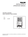
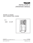
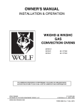
INSTALLATION &
OPERATION MANUAL
GCO SERIES GAS CONVECTION OVENS
MODEL
GCO4S
GCO4D
GCO4C
GCO6D
GCO6C
ML-52425
ML-52354
ML-52357
ML-114729
ML-114730
GCO4C
VULCAN-HART
COMPANY,
FORM 30903 Rev. B (2-98)
P.O.
BOX
696,
LOUISVILLE,
KY
40201-0696,
TEL. (502) 7 7 8 - 2 7 9 1
IMPORTANT FOR YOUR SAFETY
THIS MANUAL HAS BEEN PREPARED FOR PERSONNEL QUALIFIED TO INSTALL GAS
EQUIPMENT, WHO SHOULD PERFORM THE INITIAL FIELD START-UP AND
ADJUSTMENTS OF THE EQUIPMENT COVERED BY THIS MANUAL.
POST IN A PROMINENT LOCATION THE INSTRUCTIONS TO BE FOLLOWED IN THE
EVENT THE SMELL OF GAS IS DETECTED. THIS INFORMATION CAN BE OBTAINED
FROM THE LOCAL GAS SUPPLIER.
IMPORTANT
IN THE EVENT A GAS ODOR IS DETECTED, SHUT
DOWN UNITS AT MAIN SHUTOFF VALVE AND
CONTACT THE LOCAL GAS COMPANY OR GAS
SUPPLIER FOR SERVICE.
FOR YOUR SAFETY
DO NOT STORE OR USE GASOLINE OR OTHER
FLAMMABLE VAPORS OR LIQUIDS IN THE
VICINITY OF THIS OR ANY OTHER APPLIANCE.
WARNING
IMPROPER INSTALLATION, ADJUSTMENT,
ALTERATION OR MODIFICATION, SERVICE OR
MAINTENANCE CAN CAUSE PROPERTY
DAMAGE, INJURY OR DEATH. READ THE
INSTALLATION, OPERATING AND MAINTENANCE
INSTRUCTIONS THOROUGHLY BEFORE
INSTALLING OR SERVICING THIS EQUIPMENT.
IN THE EVENT OF A POWER FAILURE, DO NOT
ATTEMPT TO OPERATE THIS DEVICE.
–2–
TABLE OF CONTENTS
GENERAL . . . . . . . . . . . . . . . . . . . . . . . . . . . . . . . . . . . . . . . . . . . . . . . . . . . . . . . . . . . . . . . . . . . . . . . . . . . . . 4
INSTALLATION . . . . . . . . . . . . . . . . . . . . . . . . . . . . . . . . . . . . . . . . . . . . . . . . . . . . . . . . . . . . . . . . . . . . . . . . .
Unpacking . . . . . . . . . . . . . . . . . . . . . . . . . . . . . . . . . . . . . . . . . . . . . . . . . . . . . . . . . . . . . . . . . . . . . . .
Location . . . . . . . . . . . . . . . . . . . . . . . . . . . . . . . . . . . . . . . . . . . . . . . . . . . . . . . . . . . . . . . . . . . . . . . . .
Installation Codes and Standards . . . . . . . . . . . . . . . . . . . . . . . . . . . . . . . . . . . . . . . . . . . . . . . . . . . .
Installing Basic Oven . . . . . . . . . . . . . . . . . . . . . . . . . . . . . . . . . . . . . . . . . . . . . . . . . . . . . . . . . . . . . . .
Assembling the Legs to the Oven . . . . . . . . . . . . . . . . . . . . . . . . . . . . . . . . . . . . . . . . . . . . . . . . . . . . .
Leveling . . . . . . . . . . . . . . . . . . . . . . . . . . . . . . . . . . . . . . . . . . . . . . . . . . . . . . . . . . . . . . . . . . . . . . . . .
Assembling the Chimney and Flue Extension . . . . . . . . . . . . . . . . . . . . . . . . . . . . . . . . . . . . . . . . . . .
Assembling Stacked Ovens . . . . . . . . . . . . . . . . . . . . . . . . . . . . . . . . . . . . . . . . . . . . . . . . . . . . . . . . .
Assembling the Oven to the Stand . . . . . . . . . . . . . . . . . . . . . . . . . . . . . . . . . . . . . . . . . . . . . . . . . . . .
Electrical Connections . . . . . . . . . . . . . . . . . . . . . . . . . . . . . . . . . . . . . . . . . . . . . . . . . . . . . . . . . . . . . .
Gas Connections . . . . . . . . . . . . . . . . . . . . . . . . . . . . . . . . . . . . . . . . . . . . . . . . . . . . . . . . . . . . . . . . . .
Testing the Gas Supply System . . . . . . . . . . . . . . . . . . . . . . . . . . . . . . . . . . . . . . . . . . . . . . . . . . . . . .
Burner Air Shutter Adjustments . . . . . . . . . . . . . . . . . . . . . . . . . . . . . . . . . . . . . . . . . . . . . . . . . . . . . .
Flue Connections . . . . . . . . . . . . . . . . . . . . . . . . . . . . . . . . . . . . . . . . . . . . . . . . . . . . . . . . . . . . . . . . . .
OPERATION . . . . . . . . . . . . . . . . . . . . . . . . . . . . . . . . . . . . . . . . . . . . . . . . . . . . . . . . . . . . . . . . . . . . . . . . . .
Controls — Models GCO4S and GCO4D/GCO6D . . . . . . . . . . . . . . . . . . . . . . . . . . . . . . . . . . . . . .
Lighting the GCO4S and GCO4D/GCO6D Ovens . . . . . . . . . . . . . . . . . . . . . . . . . . . . . . . . . . . . . . .
Before First Use . . . . . . . . . . . . . . . . . . . . . . . . . . . . . . . . . . . . . . . . . . . . . . . . . . . . . . . . . . . . . . . . . .
Using the GCO4S and GCO4D/GCO6D Ovens . . . . . . . . . . . . . . . . . . . . . . . . . . . . . . . . . . . . . . . .
Controls — Model GCO4C/GCO6C . . . . . . . . . . . . . . . . . . . . . . . . . . . . . . . . . . . . . . . . . . . . . . . . . .
Lighting the GCO4C/GCO6C Oven . . . . . . . . . . . . . . . . . . . . . . . . . . . . . . . . . . . . . . . . . . . . . . . . . .
Before First Use . . . . . . . . . . . . . . . . . . . . . . . . . . . . . . . . . . . . . . . . . . . . . . . . . . . . . . . . . . . . . . . . . .
Using the GCO4C/GCO6C Oven . . . . . . . . . . . . . . . . . . . . . . . . . . . . . . . . . . . . . . . . . . . . . . . . . . . .
Error Messages — GCO4C/GCO6C Oven . . . . . . . . . . . . . . . . . . . . . . . . . . . . . . . . . . . . . . . . . . . .
Roast and Hold Operation . . . . . . . . . . . . . . . . . . . . . . . . . . . . . . . . . . . . . . . . . . . . . . . . . . . . . . . . .
Proper Utensils . . . . . . . . . . . . . . . . . . . . . . . . . . . . . . . . . . . . . . . . . . . . . . . . . . . . . . . . . . . . . . . . . .
Conserving Energy . . . . . . . . . . . . . . . . . . . . . . . . . . . . . . . . . . . . . . . . . . . . . . . . . . . . . . . . . . . . . . .
Operating Hints . . . . . . . . . . . . . . . . . . . . . . . . . . . . . . . . . . . . . . . . . . . . . . . . . . . . . . . . . . . . . . . . . .
Cleaning . . . . . . . . . . . . . . . . . . . . . . . . . . . . . . . . . . . . . . . . . . . . . . . . . . . . . . . . . . . . . . . . . . . . . . . .
Cooking Guidelines . . . . . . . . . . . . . . . . . . . . . . . . . . . . . . . . . . . . . . . . . . . . . . . . . . . . . . . . . . . . . . .
5
5
5
5
5
6
6
6
7
8
8
8
9
9
9
10
10
11
11
11
12
16
16
17
17
18
19
19
19
19
20
MAINTENANCE . . . . . . . . . . . . . . . . . . . . . . . . . . . . . . . . . . . . . . . . . . . . . . . . . . . . . . . . . . . . . . . . . . . . . . . . 22
Replacing Lamps . . . . . . . . . . . . . . . . . . . . . . . . . . . . . . . . . . . . . . . . . . . . . . . . . . . . . . . . . . . . . . . . . 22
Service and Parts Information . . . . . . . . . . . . . . . . . . . . . . . . . . . . . . . . . . . . . . . . . . . . . . . . . . . . . . 22
TROUBLESHOOTING . . . . . . . . . . . . . . . . . . . . . . . . . . . . . . . . . . . . . . . . . . . . . . . . . . . . . . . . . . . . . . . . . . . 23
–3–
Installation, Operation And Care Of
GCO SERIES GAS CONVECTION OVENS
KEEP THESE INSTRUCTIONS FOR FUTURE USE
Your Vulcan Gas Convection Oven is produced with quality workmanship and material. Proper installation,
usage and maintenance of your oven will result in many years of satisfactory performance.
The manufacturer suggests that you thoroughly read this entire manual and carefully follow all of the instructions
provided.
GENERAL
The Model GCO Series Convection Ovens feature a 500°F thermostat, timer, porcelain interior, and a two-speed
1
⁄2 H.P. blower motor as standard equipment. Each oven is equipped with a 40,000 BTU/hr. burner and requires
a 120 volt single phase electrical service. The oven doors open independently.
Model GCO4 is a single cavity oven. It is furnished with five racks. An open stand with lower storage rack is
available as an option.
Model GCO44 consists of two single ovens and is furnished with a stacking kit for mounting one oven on top of
the other.
Models GCO6D and GCO6C have a deeper oven cavity.
Features of the models are shown below:
MODEL
THERMOSTAT
(Each Oven)
TIMER
(Each Oven)
LEGS*
GCO4S
Mechanical
1-Hour Dial
(4) 251/4" (64cm)
GCO44S
Mechanical
1-Hour Dial
(4) 8" (20cm)
GCO4D/GCO6D
Solid State
1-Hour Dial
(4) 25 1/4" (64cm)
GCO44D/GCO66D
Solid State
1-Hour Dial
(4) 8" (20cm)
STACKING
KIT
Electronic
Electronic
(4) 25 /4" (64cm)
GCO44C/GCO66C
Electronic
Electronic
(4) 8" (20cm)
*May be Painted or Stainless Steel with Adjustable Feet or Casters
Additional racks are available as accessories.
–4–
GENTLE
BAKE
X
X
X
X
X
X
1
GCO4C/GCO6C
ROAST
&
HOLD
X
INSTALLATION
UNPACKING
Immediately after unpacking the oven, check for possible shipping damage. If this oven is found to be damaged,
save the packaging material and contact the carrier within 15 days of delivery.
Prior to installation, verify that the electrical service and type of gas (natural or propane) agree with the
specifications on the oven data plate, located on the inside of the bottom front cover.
Do not use the doors or their handle to lift the oven.
LOCATION
The equipment area must be kept free and clear of combustibles. Maintain clearances from combustible or noncombustible construction for at least 6" (152.4mm) from the sides and 6" (152.4mm) from the back of the oven.
The installation location must allow adequate clearances for servicing and proper operation.
The oven must be installed so that the flow of combustion and ventilation air will not be obstructed. Adequate
clearance for air openings into the combustion chamber must be provided. Make sure there is an adequate
supply of air in the room to allow for that required for combustion of gas at the oven burners.
INSTALLATION CODES AND STANDARDS
Vulcan ovens must be installed in accordance with:
In the United States
1. State and local codes.
2. National Fuel Gas Code ANSI-Z223.1 (latest edition), available from American Gas Association, 1515
Wilson Boulevard, Arlington, VA 22209.
3. ANSI/NFPA 96, "Vapor Removal from Cooking Equipment" (latest edition), available from National Fire
Protection Association, Batterymarch Park, Quincy, MA 02269.
4. National Electrical Code, ANSI/NFPA-70 (latest edition).
In Canada
1. Local codes.
2. CAN/CGA-B149.1, "Natural Gas Installation Code" (latest edition).
3. CAN/CGA-B149.2, "Propane Installation Code" (latest edition), available from the Canadian Gas Association,
178 Rexdale Blvd., Etobicoke, Ontario, Canada M9W 1R3.
4. Canadian Electrical Code, CSA Standard C22.2 No. 3 (latest edition), "Electrical Features of Fuel Burning
Equipment."
INSTALLING BASIC OVEN
The basic oven must be installed on legs or be mounted on a modular stand. Installations on concrete bases
or other supports restricting air circulation underneath the oven is not advisable and may void the warranty.
–5–
NOTICE: When the oven is mounted on casters, it must be installed with the casters supplied, a connector
(not supplied by Vulcan-Hart) complying with either ANSI Z21.69 (latest edition) or CAN/CGA-6.16
(latest edition), and a quick-disconnect device complying with either ANSI Z21.41 (latest edition) or CAN1-6.9
(latest edition). It must also be installed with restraining means to guard against transmission of strain to the
connector, as specified in the appliance manufacturer’s instructions. Attach the restraining device at the rear of
the oven. (Fig. 1).
CONNECT GAS
LINE STRAIN
RELIEF HERE
PL-51216
Fig. 1
ASSEMBLING THE LEGS TO THE OVEN
Unpack the oven and leg set.
Position oven on its back, taking care not to scratch or damage it. The gas pipe connection protrudes beyond
the back; provide for this when oven is tipped back by resting it on suitable spacers (2 x 4's etc.).
Attach each of the four leg assemblies to bottom of oven with the 24 bolts and lockwashers (6 per leg). Carefully
raise oven to its normal position.
LEVELING
Ensure that the oven racks are level in the final installed position. If the oven is installed on legs, turn adjustable
feet in or out to level oven front-to-back and side-to-side. If the oven is installed on casters, loosen set screws
and turn casters in or out to level oven front-to-back and side-to-side. Retighten set screws after leveling.
ASSEMBLING THE CHIMNEY AND FLUE EXTENSION
Remove the oven chimney and flue extension from the rear of the oven (motor compartment) and use the screws
provided to fasten the chimney to the top rear of the oven. Position the flanges on the chimney under the top
cover. Also attach the flue extension.
–6–
ASSEMBLING STACKED OVENS
Unpack the ovens and stack kit. Position one oven on its back for access to the oven bottom, taking care not
to scratch or damage it. The gas pipe protrudes beyond the back; provide for this when the oven is tipped back
by resting it on suitable spacers (2 x 4's, etc.). Attach the four leg assemblies with the 24 bolts and lockwashers
(6 per leg).
Place lower oven (with legs) on floor and remove two 7⁄16" (11.1mm) diameter knockouts on each side of
top cover.
Install the two locating studs (included in leg stack set) into screw plates on underside of upper oven (Fig. 2)
Fig. 2
Fig. 3
Move the oven with legs to the installed position and place upper oven on top of lower oven using the locating
studs.
Insert the right angle short flue extension into the top oven. Install the long flue extension (Fig. 3) from the stack
kit over the right angle flue extension on the top oven. Insert the right angle of the long flue extension into the
bottom oven. Secure the flue extensions with the screws provided.
Install rear panels on both ovens. Install chimney (Fig. 3) on upper oven. Connect the piping between the top
oven and bottom oven. Pipe compound must be suitable for the type of gas being used (natural or propane).
The manual gas valve at the bottom of the control panel should remain off until all electrical connections are made
and the ovens are checked or used.
–7–
ASSEMBLING THE OVEN TO THE STAND
Unpack the oven and stand. Position oven on its back, taking care not to scratch or damage it. The gas pipe
connection protrudes beyond the back; provide for this when the oven is tipped back by resting it on suitable
spacers (2 x 4's, etc.).
Install the two locating studs (included in the stand carton) into the screw plates on the underside of the oven
(see Fig. 2).
Attach each of the four leg assemblies to the bottom of the stand with the 24 bolts and lockwashers (6 per leg).
Mount the oven on top of the stand.
ELECTRICAL CONNECTIONS
WARNING: THE POWER SUPPLY CORD IS PROVIDED WITH A GROUNDING PLUG. THE OUTLET TO
WHICH THIS PLUG IS CONNECTED MUST BE PROPERLY GROUNDED. IF THE RECEPTACLE IS NOT THE
PROPER GROUNDING TYPE, CONTACT AN ELECTRICIAN.
The Model GCO Series Gas Convection Ovens are equipped with a 120 volt / 60 Hz. / 1 phase cord and plug.
A wiring diagram is located on the inside of the right side panel.
GAS AND ELECTRICAL DATA
GAS DATA
MODEL
INPUT BTU/HR
ELECTRICAL DATA
MANIFOLD PRESSURE
AMP LINE
Natural
Propane
Natural
Propane
120 Volts
40,000
40,000
3.5" W.C.
10" W.C.
10 Amps
10" W.C.
20 Amps
GCO4S
GCO4D/GCO6D
GCO4C/GCO6C
(0.8 kPa)
GCO44S
GCO44D/66D
80,000
80,000
3.5" W.C.
GCO44C/66C
(0.8 kPa)
GAS CONNECTIONS
Gas supply connections and pipe joint compound must be suitable for sealing piping for propane or natural
gases.
The oven is provided with a regulator integral to the gas solenoid valve and requires no external regulator.
The manual gas shutoff valve is located at the bottom of the front control panel.
–8–
The oven should be connected to the gas line after leveling. The gas supply line must be at least the equivalent
of 3⁄4" (19mm) iron pipe. Make sure piping is clean and free of obstructions, dirt or pipe joint compound.
WARNING: PRIOR TO LIGHTING, CHECK ALL JOINTS IN THE GAS SUPPLY LINE FOR LEAKS. USE SOAP
AND WATER SOLUTION. DO NOT USE AN OPEN FLAME.
TESTING THE GAS SUPPLY SYSTEM
The oven and its individual shutoff valve must be disconnected from the gas supply piping system during any
pressure testing of that system at test pressures greater than 1/2 psig (3.45 kPa).
The oven must be isolated from the gas supply piping system by closing the manual shutoff valve during pressure
testing of the gas supply piping system at test pressures equal to or less than 1/ 2 psig (3.45 kPa).
Gas Pressures and Orifices
Natural Gas
The burner orifices are sized to deliver the nameplate input rating (40,000 BTU/hr) at a gas manifold pressure
of 3.5" W.C. (0.8 kPa). The gas pressure regulator is integral to the gas solenoid valve and is factory set to supply
3.5" W.C. (0.8 kPa) as required for natural gas.
Propane Gas
The burner orifices are sized to deliver the nameplate input rating (40,000 BTU/hr) at a gas manifold pressure
of 10" W.C (2.5 kPa). The gas pressure regulator is integral to the gas solenoid valve and is factory set to supply
10" W.C. (2.5 kPa) as required for propane gas.
BURNER AIR SHUTTER ADJUSTMENTS
The GCO Series Oven burner has fixed, factory-adjusted air openings and requires no field adjustment.
FLUE CONNECTIONS
Ventilation requirements will vary with each installation and must comply with applicable portions of NFPA
Standard #96, "Vapor Removal from Cooking Equipment," and with local codes. Keep in mind that:
The oven should be located under a hood which has an adequate connection to an exhaust duct and extends
6" (152mm) beyond the oven sides.
Clearance above the oven flue should be adequate for the flue products to escape so that there is no
interference with the heat circulation in the ovens.
Ovens may use an optional down draft diverter flue method. This optional down draft diverter must be
purchased from the oven manufacturer; otherwise, the installation of any such device will void all oven
certifications and warranties.
–9–
OPERATION
CONTROLS — MODELS GCO4S AND GCO4D/GCO6D (Fig. 4)
;
;;
;;;
;;;;
;
;;
;;
;;
;
;
MAST
ER
SWITC
H
ON
OFF
ON
HEAT
IGNI
TION
OVEN
COOL
2 SP
EE
MOTO D
R
HI
ON
OVEN
LAMP
S
ON
OFF
LOW
MASTER SWITCH
MAST
ER
SWITC
H
ON LIGHT
HEAT LIGHT
NO IGNITION LIGHT
OVEN COOL SWITCH
ON
OFF
ON
HEAT
IGNI
OVEN
COOL
2-SPEED MOTOR
SWITCH
LOW
LIGHT SWITCH
47 5
THER
MOST
60
F
OF
60
15
TIMER
TIMER
TO SH
TO SH
PLAC OVEN UT
"OFF E MAST OFF
" PO
ER
STIO SWITC
VALV N TURN H IN
E OF
GAS
F
ON
ON
OFF
TIMER
TURN RUCTIO
PUSH GAS VA NS
LV
MAST
"ON"
ER SWE "ON"
PO
FAILS STION. ITCH TO
MAST TO LIG IF OVEN
HT
TURN ER SWITC . PUSH
GAS
H
VALV TO "OFF
5 MI
NUTE
E
"
S FO OFF WA
R RE
IT
PUSHOVEN CO TRIAL.
SWITC OL
H TO
"ON"
PLAC OVEN UT
"OFF E MAST OFF
" PO
ER
STIO SWITC
H IN
VALV N TURN
E OF
GAS
F
VALV
5
LIG
INST HTING
LIG
INST HTING
TURN RUCTIO
PUSH GAS VA NS
LV
MAST
"ON"
ER SWE "ON"
PO
FAILS STION. ITCH TO
MAST TO LIG IF OVEN
HT
TURN ER SWITC . PUSH
GAS
H
VALV TO "OFF
5 MI
NUTE
E
"
S FO OFF WA
R RE
IT
PUSHOVEN CO TRIAL.
SWITC OL
H TO
"ON"
GAS
F
OF
55
10
50
15
45
20
40
35 30 25
20
TIMER
THERMOSTAT
0
10
35 30 25
30 0
30 0
THER
MOST
AT
5
45
40
LIGHT SWITCH
25 0
35 0
THERMOSTAT
0
50
2-SPEED MOTOR
SWITCH
22 5
42 5
40 0
AT
55
OVEN COOL SWITCH
15 0
45 0
20 0
25 0
TEMP F
50 0
F
30 0
ON LIGHT
HEAT LIGHT
NO IGNITION LIGHT
OFF
45 0
35 0
OVEN
LAMP
S
ON
OFF
50 0
40 0
MASTER SWITCH
TION
2 SP
EE
MOTO D
R
HI
ON
OFF
OFF
;
;;
;
;;;
;;;
;
;;
;;
;;;
;
GAS VALVE
OFF
GAS VALVE
GAS
VALV
E
E
PL-51604
MODEL GCO4S
PL-51605
MODEL GCO4D/GCO6D
Fig. 4
MASTER SWITCH
—
ON — turns oven control circuits on.
OFF — turns oven control circuits off.
OVEN COOL SWITCH
—
Allows the fan motor to run with the doors ajar to speed oven cooling.
LIGHT SWITCH
—
Turns lights in the oven on or off.
THERMOSTAT
—
Controls oven temperature during cooking operation.
TIMER
—
Use to set cooking cycle time. Alarm sounds continuously when elapsed
time counts down to 0; oven does not turn off. Turn timer to OFF position
to stop alarm. When oven is not in use, keep timer at OFF position.
ON LIGHT (Amber)
—
Lit when Master Switch is positioned at ON.
HEAT LIGHT (White)
—
Comes on and goes off when the burner cycles on and off.
NO IGNITION LIGHT (Red)
—
Comes on if burner fails to ignite after the third try. When lighting the oven,
the NO IGNITION LIGHT cycles ON during the 5-second purge and OFF
during the 7-second ignition trial.
2-SPEED MOTOR — LO / HI
—
Adjusts air velocity in the oven.
GAS VALVE
—
When ON, allows gas to flow to the ignition system.
– 10 –
LIGHTING THE GCO4S AND GCO4D/GCO6D OVENS
Turn manual Gas Valve ON. Turn Master Switch ON and turn Thermostat to its maximum setting. Both the ON
and HEAT lights should come on. If HEAT light is not on, make sure door is closed.
After 5 seconds, the spark ignition system will start and the solenoid valve will open, allowing gas to flow to the
burner for 7 seconds. This 5-second purge and 7-second ignition trial will repeat up to two more times if the
burner does not light within the first 7-second ignition trial. During this 5-second prepurge, the red NO IGNITION
light will be lit.
When the burner gas ignites, a slight "roar" will be heard. This "roar" is a normal condition of the power burner
and will become almost undetectable in the normal operating mode after warm-up. The NO IGNITION light will
go off when ignition occurs.
If the burner fails to light, the red NO IGNITION light will be lit and remain on. Turn Master Switch OFF. Turn
manual Gas Valve OFF. Wait for five minutes before repeating lighting sequence previously described.
If the burner does not light after three trials, turn off the manual Gas Valve and call a qualified servicer.
BEFORE FIRST USE
Before using the oven for the first time, it must be "burned in" to release any odors that might result from heating
the new surfaces in the chamber.
1. Using a clean damp cloth, wipe the inside of the oven, including the racks.
2. Close the oven doors, turn the Master Switch ON, turn the Thermostat to 300°F (149°C) and allow the
oven to cycle for 6 to 8 hours before turning the Master Switch OFF.
USING THE GCO4S AND GCO4D/GCO6D OVENS
Preheating
1. Turn Master Switch ON. Amber ON light will come on, indicating that power to oven is on.
2. Set Thermostat as desired. Refer to COOKING GUIDELINES for suggested temperatures and times for
various products.
3. Prepare product and place in suitable pans. When white HEAT light goes off, oven has reached desired
preheat temperature.
Cooking
1. Open doors and load the product into the oven. Place pans in the center of the racks. Close doors.
2. Set the Timer. After the preset time lapses, turn timer to OFF position to stop alarm.
3. When product is done, open doors and carefully remove cooked product from the oven. Wipe up any spills.
End of Day
1. Turn thermostat to OFF.
2. Turn Oven Cool Switch ON. Leave door ajar while the fan is on to cool the oven.
3. When oven has cooled sufficiently, turn Oven Cool Switch and Master Switch to OFF and clean the oven.
– 11 –
CONTROLS — MODEL GCO4C/GCO6C (Fig. 5)
TEMPE
RATURE
THERMOSTAT
HEAT
READ
Y
ROAS
T
HOLD
TIME
TIME
TIMER
START
STOP
GENTL
E
BAKE
2 SPEED FAN - HI / LO
FAN
SPEED
LIGHTS
HI
ON
;;
;;;
;;
;
LIGHT SWITCH
LOW
OFF
POWE
R
ON
OFF
ON / OFF / OVEN COOL
SWITCH
OVEN
COOL
LIGHT
IN
TURN G INST
PUSH GAS VARUCTIO
NS
LV
MAST
"ON"
ER SWE "ON"
PO
FAILS STION. ITCH TO
MAST TO LIG IF OVEN
HT
TURN ER SWITC . PUSH
GAS
H
VALV TO "OFF
5 MI
NUTE
E OF
"
S FO
F
R RE WAIT
TRIAL
TO SH
.
PLAC UT-O
VEN
"OFF E POWE
OFF
VALV" POSTIOR SWITC
E OF
N TU
H IN
F
RN GA
S
ON
OFF
GAS
VALV
GAS VALVE
E
PL-51606
MODEL GCO4C/GCO6C
Fig. 5
THERMOSTAT CONTROL
Temperature Display (When Not Timing Product)
Displays set cook temperature while the light in the Roast Button is lit. Will be overridden
to display actual cavity temperature for 8 seconds when Thermometer Button is pushed.
1. The light in the Thermometer Button will be lit while the actual temperature
is being displayed.
2. The light in the Thermometer Button will extinguish when the display returns
to set temperature display.
Temperature Display (When Timing Product)
Displays set hold temperature while the light in the Hold Button is lit. Displays the roast
temperature when the Roast Button is lit. Will be overridden to display actual cavity
temperature for 8 seconds when the Thermometer Button is pushed.
1. The light in the Thermometer Button will be lit while actual temperature is
being displayed.
2. The light in the Thermometer Button will extinguish when the display returns
to set temperature display.
– 12 –
Temperature Knob (When Not Timing Product)
1. Sets the roast temperature when the Roast Button light is lit. The Roast
Button light can be turned on by pressing the Roast Button.
2. Sets the hold temperature when the Hold Button light is lit. The Hold Button
light can be turned on by pressing the Hold Button.
Temperature Knob (When Timing Product)
1. Sets the roast temperature when the Roast Button light is lit. The Roast
Button light cannot be changed by pressing the Roast Button.
2. Sets the hold temperature when the Hold Button light is lit. The Hold Button
light cannot be changed by pressing the Hold Button.
Roast Button Light (If On) - (While Not Timing Product)
Indicates the roast mode is selected. This means:
1. The displayed temperature settings will be for the roast temperature except
for the time that the light in the Thermometer Button is lit.
2. Rotating the Thermostat Knob will change the roast set temperature.
3. Cook time can be adjusted using the Timer Knob.
4. The time displayed is the initial set cook time.
5. It is possible to select the Hold mode using the Hold Button.
Roast Button Light (If On) - (While Timing Product)
Indicates the roast mode is selected. This means:
1. The displayed temperature settings will be for the roast temperature except
for the time that the light in the Thermometer Button is lit.
2. Rotating the Temperature Knob will change the roast set temperature.
3. It is not possible to select the Hold mode using the Hold Button.
4. The time displayed is the time counted down from the initial cook time set.
Roast Button
1. Lights the Roast Button light. See Roast Button Light above.
2. Selects the Roast mode.
3. Has no effect if timing in the Hold mode.
– 13 –
Thermometer Button
When pressed, causes actual cavity temperature to display for about 8 seconds, then
display returns to set temperature.
Heat Light
When lit, indicates that power is being supplied to the burner.
Ready Light
Will be lit any time the actual temperature is within +/- 5°F (+/- 2.7°C) of the set temperature
for the current mode.
TIMER CONTROL
Time Display (While Not Timing Product)
Displays the set cook time if the light in the Roast Button is lit.
Time Display (While Timing Product)
1. Displays the counted down cook time if the Roast Button light is lit and in the
Roast mode.
2. Displays the counted up hold time if the Hold Button light is lit and in the
Hold mode. Count-up of hold time does not begin until cavity temperature
reaches the hold temperature.
Time Display Semicolon
1. Flashing if product is timing.
2. Not flashing if not timing product.
Time Button
Press to set cooking cycle time.
Time Button Light
Illuminates when the Time Button is pressed.
Timer Knob
Sets the cook time when not already timing and the Cook Time indicator is lit.
– 14 –
Gentle Bake Button
Selects the gentle bake time setting. A roast time must be set first. The gentle bake
time can then be set equal to or less than the roast time. The gentle bake time will be
the portion of roast time to operate in the gentle bake mode. Gentle bake mode will start
first. When gentle bake time elapses, the remainder of the roast time will be in the nongentle bake mode.
Use when cooking delicate product, such as strudel, muffins, cupcakes, meringue pies,
etc., to keep product from forming "waves" on the top.
Use the Gentle Bake Button to switch between the selection of gentle bake mode and
no gentle bake mode time setting. A gentle bake mode time of zero means no gentle
bake mode will occur.
The light in the Gentle Bake Button will be lit when in the gentle bake mode.
In Gentle Bake Mode:
1. The fan cycles (45 seconds ON and 45 seconds OFF) for the duration of the
gentle bake cycle time.
2. The fan stays on while the heat cycles in hold mode.
3. The fan stays on while heat cycles at 100% power when not timing.
4. Can be switched at any time.
Stop/Start Button
1. Initiates timing a product in the mode selected if a cook time has been set.
2. Stops timing of a product if a timing sequence has already started.
Hold Button
Selects Hold mode.
1. Allows selection of hold temperature.
2. Temperature indication of ---°F (---°C) indicates no hold mode.
Hold Button Light
Is lit when in the Hold mode.
1. When not timing, allows setting/enabling a hold mode setting of ---°F
(---°C), meaning no hold will take effect.
2. Any other temperature means that when the actual cook time has ended, the
oven will enter the Hold mode and use the hold temperature.
– 15 –
ON/OFF/OVEN COOL SWITCH
1. ON turns oven control circuits on.
2. OFF turns oven control circuits off.
3. OVEN COOL allows the fan motor to run with the doors ajar to speed oven
cooling.
2-SPEED FAN SWITCH
Adjusts air velocity in the oven.
LIGHT SWITCH
Turns lights in the oven on or off.
GAS VALVE
When ON, allows gas to flow to the ignition system.
LIGHTING THE GCO4C/GCO6C OVEN
1. Turn manual Gas Valve ON.
2. Push On/Off/Oven Cool switch to the ON position and set Thermostat to its maximum setting. The Heat light
should come on. If Heat light is not on, make sure door is closed.
3. If the oven fails to light, push On/Off/Oven Cool switch to the OFF position. Wait 5 minutes before retrial.
BEFORE FIRST USE
Before using the oven for the first time, it must be "burned in" to release any odors that might result from heating
the new surfaces in the chamber.
1. Using a clean damp cloth, wipe the inside of the oven, including the racks.
2. Close the oven doors, push the On/Off/Oven Cool switch to the ON position, turn the Thermostat to
300°F (149°C) and allow the oven to cycle for 6 to 8 hours before turning the On/Off/Oven Cool switch OFF.
– 16 –
USING THE GCO4C/GCO6C OVEN
Preheating
1. Turn On/Off/Oven Cool switch to ON position. The Heat light will come on, indicating that power to the oven
is on.
2. Set Thermostat as desired. Refer to COOKING GUIDELINES for suggested temperatures and times for
various products.
3. Prepare product and place in suitable pans. When Ready light comes on, oven has reached desired preheat
temperature.
Cooking
1. Open doors and load the product into the oven. Place pans in the center of the racks. Close doors.
2. Set Roast temperature and time. Set Hold temperature and Gentle Bake time, if desired. Gentle Bake time
may not be more than roast time. Gentle Bake will cycle the fan during the set time at the beginning of the
cooking cycle.
3. Press the Start/Stop button to start the cooking cycle.
4. At the end of the cooking cycle, the buzzer will sound continuously if the Hold mode is OFF. If the Hold mode
is ON, there will be a short beep at the beginning of Second Stage Cooking (oven temperature will begin to
decline to the Hold temperature), and a long beep (20 seconds) at the end of the cooking cycle. (See ROAST
AND HOLD OPERATION.)
5. When product is done, open doors and carefully remove cooked product from the oven. Wipe up any spills.
End of Day
1. Push On/Off/Oven Cool switch to OVEN COOL. Leave door ajar while the fan is on to cool the oven.
2. When oven has cooled sufficiently, push On/Off/Oven Cool switch to OFF position and clean the oven.
ERROR MESSAGES — GCO4C/GCO6C OVEN
E-01
E-02
E-03
E-04
E-05
E-06
High limit error. Contact your local Vulcan authorized service representative.
Low limit error. Contact your local Vulcan authorized service representative.
High ambient temperature (215°F/101.7°C). Contact your local Vulcan authorized service representative.
Low ambient temperature (32°F/0°C). Let control warm up after cold storage.
Ignition failure. After trying ignition 3 times, contact your local Vulcan authorized service representative.
Thermocouple probe open. Contact your local Vulcan authorized service representative.
When calling for service, please advise what error code was displayed.
– 17 –
ROAST AND HOLD OPERATION
Roast and Hold cooks the product in two stages. During First Stage Cooking, the oven temperature is regulated
by the Roast thermostat for the amount of time set on the Timer. After the lapsed time counts down to 00:00,
Second Stage Cooking begins. During Second Stage Cooking, the burners are off as the temperature in the oven
declines to the Hold Temperature. The doors should remain closed during Second Stage Cooking.
When the Hold temperature is reached, cooking is done. The Time Display counts up the Hold time and flashes
"Hold." Temperature in the oven will be maintained at the Hold temperature until the oven is turned off.
ROAST AND HOLD DIAGRAM - Time vs. Temperature
OVEN TEMPERATURE
TIMER DISPLAY COUNTS DOWN,
COLON FLASHES.
400ºF
300ºF
SHORT BEEP.
TIMER DISPLAY FLASHES 00:00.
ROAST THERMOSTAT OFF.
BURNERS OFF UNTIL HOLD
TEMPERATURE IS REACHED.
COOKING FROM
STORED HEAT
LONG BEEP (20 SEC.)
BURNERS MAINTAIN
HOLD TEMPERATURE.
TIMER DISPLAY COUNTS UP
HOLD TIME AND FLASHES
"HOLD."
200ºF
LOAD PRODUCT
INTO OVEN
100ºF
TEMP.
T
DUC
PRO
PREHEAT
URE
RAT
PE
TEM
FIRST STAGE COOKING
SECOND STAGE
COOKING
(DO NOT OPEN
DOORS)
TIME
PL-51607
– 18 –
HOLDING
PROPER UTENSILS
The use of proper utensils can enhance oven operation. Medium and light weight pans allow the product to warm
faster. Roast meats in shallow pans deep enough to hold all juices yet allow free air circulation.
CONSERVING ENERGY
•
•
•
•
•
•
•
Turn off unused equipment.
Adjust menu patterns and cooking/baking schedules for optimum equipment use.
Reduce thermostat settings in slack periods since gas equipment heats up and recovers quickly.
Preheat only to required cooking temperature for specific food — not higher.
Do not open the oven door unless absolutely necessary.
Keep area around the oven door clean and free of food particles.
Any obstruction that prevents the door from closing completely will adversely affect oven efficiency.
OPERATING HINTS
When using the convection oven for the first time with a particular food, check the degree of doneness
periodically before the suggested time has elapsed, to make sure the desired doneness is achieved.
Record your temperature and time settings for various products. The convection oven can provide consistent,
repeatable results.
The convection oven is faster than conventional deck-type ovens; temperature settings are lower and cook times
are shorter. Since recipes and foods are subject to many variations and tastes, the guidelines regarding Times
and Temperatures in this manual are SUGGESTIONS ONLY. Experiment with your food products to determine
the cooking temperatures and times that give you the best results.
CLEANING
WARNING: TURN OVEN OFF AND UNPLUG ELECTRICAL CORD BEFORE CLEANING.
Clean outside of the oven daily by wiping with a clean damp cloth.
Clean porcelain oven interior daily with soap or detergent and water. Rinse thoroughly and wipe dry with a soft
clean cloth.
Optional Stainless Steel Oven Interior
Soap or detergent and water usually handle routine cleaning. Rinse thoroughly, dry with a soft clean cloth.
For burned-on foods and grease which resist simple soap and water cleaning, an abrasive cleanser (scouring
powder) mixed into a paste may be used. Apply with stainless steel wool or sponge, always rubbing with the
"grain."
This treatment is equally effective for "heat tint" (slightly darkened areas caused by oxidation). Again, remember
to rub in the direction of the polish lines. Rinse with clear water and dry with a soft cloth.
– 19 –
COOKING CHARTS
Models GCO4S, GCO4D/GCO4C and GCO6D/GCO6C
BAKED PRODUCTS
Product
Sheet Cakes (5 lb. each) (2.3 kg)
Soda Biscuits
Yeast Rolls
Corn Bread
Gingerbread
Chocolate Cake
Chocolate Chip Cookies
Sugar Cookies
Yellow Cake
Angel Food Cake
Brownies
Apple Turnovers
Cream Puffs
Apple Pie (Fresh)
Pumpkin Pie
Berry Pies (Frozen)
Fruit Pie (Frozen)
Pizza (Individual, Frozen)
(Precooked Crust)
Bread (1 lb. loaf) (454 gr.)
Brown and Serve Rolls
Coffee Cake
Pineapple Upside Down Cake
Fruit Cobbler
Danish Pastry
Pie Shells
Cinnamon Buns
*
**
(°F)
300
325
325
300
300
325
325
Temp.
(°C)
(149)
(163)
(163)
(149)
(149)
(163)
(163)
326
300
275
350
350
300
350
275
325
325
(163)
(149)
(135)
(177)
(177)
(149)
(177)
(135)
(163)
(163)
310-325 (154-163)
340
350
300
325
375
325
350
325
(171)
(177)
(149)
(163)
(190)
(163)
(177)
(163)
Some people prefer high speed for darker cheese.
Low speed will give you a more uniform color.
– 20 –
Time (min.)
No. Shelves
Fan Speed
30
12
15-20
15
18
20
10
5
5
5
5
3
5
5
Low
Low
Low
Low
Low
Low
Low
12
25
25
15-20
20-25
25-30
30
40
40
45
5
5
5
5
5
5
5
5
5
5
Low
Low
Low
Low
Low
Low
High
High
High
High
8-13
5
Low/High*
30
15
45
30
25
12-15
12
15-20
3
5
3
5
5
5
5
5
High/Low**
Low
High
High
High
Low
Low
Low
MEAT & FISH PRODUCTS
Product
Prime Rib (20 lb. rare (9 kg)
Rolled Roast Beef
Veal Roast Boned (15 lb.) (7 kg)
Stuffed Pork Chops
Lamb Chops
Steamship Round (80 lb.) (36.3 kg)
Meatloaf
Hamburger Patties (4 oz.) (113 gr.)
Meat Pot Pies
Chicken Parts
Fish Sticks
Temp.
(°F)
(°C)
250
(121)
275
(135)
275
(135)
300
(149)
375
(190)
275
(135)
325
(163)
400
(204)
375
(190)
300-325 (149-163)
350
(177)
Time (min.)
No. Shelves
Fan Speed
2 3⁄ 4 Hr.
2 1⁄ 2 Hr.
2 1⁄ 2 Hr.
25-30
12
3
2 ⁄ 4 Hr.
40
8-10
40
30-40
18
2
2
2
3
5
1
3
5
5
5
5
High
High
High
High
High
High
High
High
High
High
High
Time (min.)
No. Shelves
Fan Speed
30
10
45
55
20
35
90
3
5
5
5
5
5
3
High
Low
High
High
High
High
High
MISCELLANEOUS PRODUCTS
Product
Macaroni & Cheese
Cheese Sandwiches
Baked Potatoes (6-8 oz.) (170-227 gr.)
Baked Potatoes (10 oz.) (283 gr.)
Stuffed Peppers
Scalloped Potatoes
Lasagna
(°F)
350
375
450
450
350
325
250
Temp.
(°C)
(177)
(190)
(232)
(232)
(177)
(163)
(121)
FOR BEST RESULTS
Product to be cooked should be centered on the oven rack, and the racks should be spaced evenly within the
oven cavity.
It is best not to rotate the product or open the doors during the cooking cycle.
Preheat oven to 50° (10°C) higher than desired cooking temperature. After the oven is loaded, close the door
and set thermostat to desired cooking temperature.
Make adjustments in the time, temperature and fan speed settings until the desired results are obtained. Adjust
only one setting at a time. For example, if the product is too dark on the outside and not done on the inside, it
is cooking too fast. Try reducing the temperature by 25°F (4°C).
These cooking charts will be helpful in arriving at time, temperature and fan speed settings for products commonly
cooked in convection ovens, but since each user’s perception of how a particular product should be finished
will be different, it may be necessary to make adjustments in the settings until the desired results are obtained.
When the desired results are obtained, make a note of the settings used for a particular recipe and product
load. For example, if the user typically bakes four 18" x 26" (45.7cm x 66cm) sheet cakes using 5 lb. (2.26 kg)
of batter for each cake, that would constitute a typical product load for that recipe. If the size of the load is
changed, it may affect the final results. If the user changes either the weight of the cakes being baked, or the
number of cakes being baked at a time, it may be necessary to make further adjustments in the time or
temperature settings to achieve the desired results.
– 21 –
MAINTENANCE
WARNING: TURN OVEN OFF AND UNPLUG POWER SUPPLY CORD BEFORE PERFORMING ANY
MAINTENANCE.
The fan motor comes with sealed bearings and requires no lubrication.
If this oven is placed on casters, it should be connected to the supply piping with the proper disconnect device
and restraint. If it is necessary to disconnect the restraint, first turn off the gas supply. Reconnect the restraint
before turning the gas supply on and returning the oven to its original installation position.
Annually check the flue, when cool, to be sure it is free of obstructions.
REPLACING LAMPS
•
•
•
•
•
•
Allow oven to cool.
Remove all racks by pulling forward, lifting up and out.
Remove the right rack support by lifting up.
Unscrew glass dome(s) from light body.
Replace the bulb(s).
Reassemble glass dome(s), rack support and racks by reversing the disassembly procedure.
SERVICE AND PARTS INFORMATION
To obtain service and parts information concerning your GCO Series Oven, contact the Vulcan-Hart Service
Depot in your area (refer to listing supplied with this oven), or Vulcan-Hart Company Service Department at the
address or phone number shown on the front cover of this manual.
– 22 –
TROUBLESHOOTING
If NO IGNITION LIGHT remains lit for more than 20 seconds after three trials (Models GCO4S AND GCO4D/
GCO6D), or "E-05" appears in the display after three trials (Model GCO4C/GCO6C):
•
•
•
Turn oven off for 5 minutes before attempting to relight.
Check gas supply valves to be sure they are open.
Check electrical power source and connections.
Contact personnel qualified to install and repair gas equipment for any other service problems.
– 23 –
NOTES
FORM 30903 Rev. B (2-98)
– 24 –
PRINTED IN U.S.A.