1
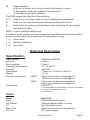
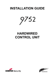
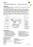
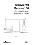
9940/9941 Keypads A B C D Installation Guide Introduction The 9940 and 9941 keypads are designed to work with 9853, 9851, 9752, 9751 and 9651 alarm system control units. These keypads are a direct replacement for the 9930, and offers the advantage of smaller size and improved appearance. The 9940 keypad has a proximity tag reader coil fitted inside the case and can work with the same proximity tags as the 934 proximity reader module. The 9941 has no detector coil fitted. A B C 1 2 3 4 5 6 7 8 9 D 0 Figure 1. 9940 Remote Keypad. Operator Controls and Displays The 9940 and 9941 keypads have a two line by 16 character LCD display that shows “first to alarm” information, level status, and programming commands. In addition there are three LEDs with the following functions: Page 2 Glows steadily when mains power is present. Flashes when the system is working from battery backup. Glows steadily when the system requires the user to acknowledge an alert. 11681330 Issue 1 Glows steadily if: a) A fault or tamper circuit is active while the system is unset. b) The system needs an engineer or remote reset. c) A telephone line fault is present. The 9940 keypad provides the following keys: 9 - 0 Used to key in access codes or select programming commands. Used to enter programming and setting/unsetting commands. Used to set the system with individual zones (including 24 hour zones) temporarily omitted. ABCD Level or partition setting keys In addition, some control units may support the Dual Key Alarm function to allow users to start an alarm by pressing the following pairs of keys: 1 + 3 Panic alarm 4 + 6 Medical assistance 7 + 9 Fire alarm Technical Description Specification Sales number Security Environmental Operating temperature Humidity Dimensions Weight Current consumption (9940) (9941) Compliance Inputs Name Panic Ext Tamper ET Data, CLK 12V, 0V 9940EN or 9941EN Grade 3 Class II -10° to +55°C 96% RH 115mm W, 115mm H, 24mm D 0.2 kg 30mA max continuous backlight off 70mA max continuous backlight on. 20mA max continuous backlight off 60mA max continuous backlight on. EN51031-1 For further detail and Declaration of Conformity please go to www.coopersecurity.co.uk. CE Telefication Used For: External wired PA button. External tamper switch or wiring. Exit Terminate button. Signal from control unit keypad bus. DC power supply. 11681330 Issue 1 Page 3 Compatible Equipment 9853 9851 9752 9751 9651 PCB To gain access to the PCB and its connectors, undo the screws at the bottom of the case and lift the front away from the back plate. Figure 2 shows the layout of the control unit PCB. 6 5 4 1 3 2 1. Sounder. 2. Tamper switch. 3. Connectors. 4. Volume control. 5. Addressing and backlight jumpers. 6. Proximity reader coil (9940 only) Figure 2. Control Unit PCB Layout Page 4 11681330 Issue 1 Installation Cabling Keypads Cooper Security recommend that you use 8-core 7/0.2 or 16/0.2 alarm cable for wiring keypads You can connect the keypads in either a star or bus configuration. If you are intending to use long cable runs then Cooper Security recommend that you use star wiring with no more than 200m of cable per branch. Siting Restrictions (9940 only) The 9940 keypad contains a coil inside the case that acts as the sensor for proximity tags used to set and unset alarm systems. The coil works at a low radio frequency and has a spherical detection pattern of roughly 120mm radius. This detection sphere can extend through wood, brick, plaster, glass and plastic walls. Electromagnetic devices, including other 9940 or 9950 keypads, can interfere with the operation of the coil. When siting the keypad: Avoid magnetic devices, for example: electric motors, door releases, microwave detectors or ovens. Avoid large metal structures. Remember that screwing a keypad to a metal frame may significantly alter the detection range Avoid fitting keypads anywhere near an entryphone, loudspeaker, PA system, or other proximity reader or security tagging system Do not put two keypads back to back even if there is a wall between them If any of these conditions are present, you should test the operation of the keypad with a prox tag at the proposed site before permanently installing the keypad. In addition, remember to warn users that holding a mobile phone in the same hand as a tag may seriously affect the reading performance. 11681330 Issue 1 Page 5 Fitting a 9940 or 9941 Keypad Figure shows the backplate and the position of mounting holes. 4 3 1. Cable entry. 2. Mounting holes. 3. Back tamper aperture. 4. Sounder aperture. Figure 3. Backplate of 9940/9941 Keypad Cooper Security recommend that you mount the keypad using M4/M3.5 screws as follows: 1. Select which cable entry you are going to use and break out the appropriate plastic sections. 2. Hold the backplate in place against the wall and mark the position of one fixing hole. 3. Drill and plug the hole, and screw the backplate to the wall. Do not tighten the screw completely home. 4. Make sure the backplate is level and mark, drill and plug at least two other fixing holes. Screw the backplate to the wall through the fixing holes. 6. Mount the front of the keypad (containing the keypad pcb) onto the backplate and make sure that the tamper switch operates. Page 6 11681330 Issue 1 Keypad Addressing If you have fitted several keypads to one control unit, then each keypad must be given a separate “address”. Links LK2 to LK4 set the keypad address, as shown in Figure 4. Keypad 1 Address Keypad 2 2 2 2 3 3 3 4 4 4 Keypad 3 Keypad 4 2 2 3 3 4 4 ON BACKLIGHT ON BACKLIGHT ON BACKLIGHT Backlight ON Backlight OFF Figure 4. Keypad Addressing. Keypad Backlight When supplied from the factory the keypad is configured with the backlight OFF. To turn the keypad backlight ON fit the supplied jumper to both pins of the “ON BACKLIGHT” link, shown in Figure 4. Connecting Exit Terminate or Panic Buttons To connect an exit terminate button use the “ET” connector terminals on the keypad PCB. Use the “ET” connector terminals to connect a Lock Switch. If using a lock switch do not connect any other device to the “ET” terminals. 11681330 Issue 1 Page 7 © Cooper Security Limited 2006 Every effort has been made to ensure that the contents of this leaflet are correct . However, neither the authors nor Cooper Security Limited accept any liability for loss or damage caused or alleged to be caused directly or indirectly by this leaflet. The contents of this leaflet are subject to change without notice. Printed and published in the U.K. Product Support (UK) Tel: +44 (0)870 757 5400 Available between: 08:15 and 17:00 Monday to Friday, Product Support Fax: (01594) 545401 Page 8 11681330 Issue 1