1
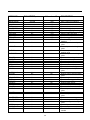
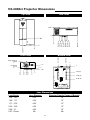
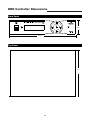
OWNER’S OPERATING MANUAL
VX-4000ci Projector
& DHD™ Controller
Widescreen Digital Light Processing™ Projector &
DHD™ Video Controller with Vivix™ Technology
Table of Contents
Introduction ...................................................................................................................... 3
Warnings and Safety Precautions.................................................................................. 4
Warning ........................................................................................................................ 5
Safety Tips.................................................................................................................... 5
Limited Warranty.............................................................................................................. 6
Features and Benefits .................................................................................................... 8
Projector Description ...................................................................................................... 9
Top View ...................................................................................................................... 9
Input Panel .................................................................................................................. 9
Ceiling Mount Dimensions............................................................................................ 10
Horizontal and Vertical Lens Shift................................................................................ 11
Lens Shift Range............................................................................................................ 12
Lens Adjustments .......................................................................................................... 15
ProntoNeo Remote Control Description .................................................................... 17
Battery Installation and Replacement ........................................................................ 18
ProntoNeo Remote Control Usage .............................................................................. 19
DHD Controller Description .......................................................................................... 20
Front Panel ................................................................................................................ 20
Rear Panel ................................................................................................................ 21
Quick Set-up Guide ...................................................................................................... 22
Connection Example .................................................................................................. 22
Overall Functional Description .................................................................................... 24
Menu Description and Navigation................................................................................ 25
Lens Replacement Procedure ...................................................................................... 29
Basic Troubleshooting Tips.......................................................................................... 32
RS-232 Communications .............................................................................................. 34
RS-232 Commands ........................................................................................................ 35
Dimensions .................................................................................................................... 37
Specifications ................................................................................................................ 39
1
2
Introduction
The new VX-4000ci builds off of the versatility of the VX-5000c DLP™ by employing Runco's 3rd
Generation engineering practices. The GEN 3 features included with the VX-4000ci are: motorized
Reflectance Volume Regulation (RVR), digital video input with HDCP, 9 point Color Balance, and the
high contrast 16:9 HD2+ DMD (Digital Micro-Mirror Device) from Texas Instruments. The remote controlled Reflectance Volume Regulation (RVR) allows adjustable iris control of contrast ratio versus light
output for the best imaging performance in any viewing environment. The digital video input with HDCP
permits the signal to stay digital through the entire signal path. A 9-point color balance, accurately
adjusts color balance for some of the best gray-scale tracking available on a consumer DLP. The HD2+
DMD generates an exceptionally high contrast ratio for high light output and better black level than
obtainable with FILM. By incorporating 6 customizable lens optics a wider range of specified throw distances from 0.67:1 (for rear-screen applications) to over 5.7:1 can be projected in a large living space
or concealed behind a cabinet. The VX-4000ci projector system also includes the DHD™ Controller
with VIVIX™ technology upconverting standard definition sources to virtual high Definition. For added
flexibility, horizontal and vertical lens shift allows the most versatility in placement ever available on a
consumer projector.
Features
• Native 1280x720, Single HD2+ 16:9 DMD Chip, incorporating an advanced 7-segment color filter
• Enhanced GEN 3 Technology with RVR or Reflectance Volume Regulation
• 6 lens options for the most versatility of a 720p DLP
• 16:9 Widescreen Native Resolution - Designed exclusively for 16:9 aspect screens
• Multiple aspect ratio (on 16:9 screens) - Anamorphic, Letterbox, 4:3, VirtualWide
• 2500:1 Contrast Ratio
• DVI-I Input
• HDTV capable (via an outboard DTV decoder); 720 (native), 1080i, 480p, 540p
• PAL compatible
• 3:2 pulldown detection
• Horizontal and Vertical lens shift
• Vertical Electronic Keystone Correction
Included Accessories
• ProntoNeo Remote Control with 3 AA batteries
• Rack Mount hardware for the DHD Controller
• Power cables (one for Projector, one for DHD Controller)
• 50’ RJ-11 phone type cable
• 6” RGBHV Extension
• D-Sub9 to RJ-11
• 3/16 Allen Tool for lens adjustment
• User’s Manual
• Warranty information
3
Warnings and Safety Precautions
WARNING
FCC Regulations state that any unauthorized changes or modifications to this equipment not expressly
approved by the manufacturer could void the user's authority to operate this equipment.
CAUTION: TO PREVENT FIRE OR SHOCK HAZARDS, DO NOT REMOVE COVER.
DO NOT EXPOSE THIS UNIT TO RAIN OR MOISTURE. ALSO DO NOT USE THIS UNIT'S POLARIZED PLUG WITH AN EXTENSION CORD RECEPTACLE OR OTHER OUTLETS, UNLESS THE
PRONGS CAN BE FULLY INSERTED. REFRAIN FROM OPENING THE CABINET AS THERE ARE
HIGH-VOLTAGE COMPONENTS INSIDE. NO USER-SERVICEABLE PARTS EXCEPT LAMP UNIT.
REFER SERVICING TO QUALIFIED SERVICE PERSONNEL.
WARNING
High brightness light source. Do not stare into the beam of light, or view directly. Be especially careful
that children do not stare directly into the beam of light.
WARNING
The cooling fan in this projector continues to run for about 90 seconds after the projector is turned off.
During normal operation, when turning the power off always use the power (OFF) button on the projector or on the remote control. Ensure the cooling fan has stopped before disconnecting the power cord.
The power outlet socket should be installed as near to the equipment as possible, and should be easily accessible.
DURING NORMAL OPERATION, NEVER TURN THE PROJECTOR OFF BY DISCONNECTING THE
POWER CORD. FAILURE TO OBSERVE THIS WILL RESULT IN PREMATURE LAMP FAILURE.
PRODUCT DISPOSAL
This projector utilizes tin-lead solder, high intensity discharge lamp (HID lamp) containing a small
amount of mercury. Disposal of these materials may be regulated due to environmental considerations.
For disposal or recycling information, please contact your local authorities or, if you are located in the
United States of America, the Electronic Industries Alliance: www.eiae.org.
INFORMATION
This equipment has been tested and found to comply with the limits for a Class B digital device, pursuant to Part 15 of the FCC Rules. These limits are designed to provide reasonable protection against
harmful interference in a residential installation. This equipment generates, uses, and can radiate radio
frequency energy and, if not installed and used in accordance with the operation manual, may cause
harmful interference to radio communications. However, there is no guarantee that interference will not
occur in a particular installation. If this equipment does cause harmful interference to radio or television
reception, which can be determined by turning the equipment off and on, the user is encouraged to try
to correct the interference by one or more of the following measures:
• Reorient or relocate the receiving antenna.
• Increase the separation between the equipment and the receiver.
• Connect the equipment into an outlet on a circuit different from that to which the receiver is
connected.
• Consult the dealer or an experienced radio/TV technician for help.
4
Declaration of Conformity
RUNCO PROJECTOR, MODEL VX-4000ci
This device complies with Part 15 of the FCC rules. Operation is subject to the following conditions: (1)
This device may not cause harmful interference, and (2) this device must accept any interference
received, including interference that may cause undesired operation.
WARNING
Some IC chips in this product include confidential and/or trade secret property belonging to Texas
Instruments. Therefore you may not copy, modify, adapt, translate, distribute, reverse engineer, reverse
assemble or discompile the contents thereof.
INTELLECTUAL PROPERTY RIGHTS
----- IMPORTANT ----READ BEFORE USING THE PRODUCT
• Digital Light Processing, DLP, Digital Micromirror Device and DMD are trademarks of Texas
Instruments.
• Microsoft and Windows are registered trademarks of Microsoft Corporation in the United States
and/or other countries.
• PC/AT is a registered trademark of International Business Machines Corporation in the United
States.
• Adobe Acrobat is a trademark of Adobe Systems Incorporated.
• Macintosh is a registered trademark of Apple Computer, Inc. in the United States and/or other
countries.
• Minolta is a registered trademark of Minolta Co., Ltd.
• All other company or product names are trademarks or registered trademarks of their respective
companies.
SAFETY TIPS
Please read and follow the safety precautions listed below to ensure the equipment is free from
damage, and to ensure that no injury will occur as a result of improper use.
· Do not insert any object, especially metal or liquids, into the Projector or DHD Controller.
· Do not place any objects containing water or any other liquid on top of the Projector or DHD
Controller.
· Do not place the units in direct sunlight, near heaters or in extremely dusty or humid locations.
· Do not install this system outdoors or otherwise exposed to the elements.
· Do not place heavy objects on top of the Projector or Controller.
· If the power cord is damaged or frayed in any way, electrical shock and/or fire may result. Please do
not place objects on the power cord, and keep the cord away from heat-emitting devices. Should the
power cord become damaged in any way, please contact your Runco Dealer for a replacement cord.
· Do not remove the cover of the Projector or DHD Controller for any reason. If any problems arise
with the unit, please contact a Runco Dealer or Runco International for service. Removing the covers
will void the warranty.
5
Limited Warranty
LIMITED WARRANTY
Congratulations on your purchase of a Runco video product and welcome to the Runco family! We
believe Runco produces “The World’s Finest Home Theater Products”. With proper installation, setup
and care, you should enjoy many years of unparalleled video performance. Please read this consumer
protection plan carefully and retain it with your other important documents.
This is a LIMITED WARRANTY as defined by the U.S. Consumer Product Warranty and Federal Trade
Commission Improvement Act.
WHAT IS COVERED UNDER THE TERMS OF THIS WARRANTY:
SERVICE LABOR: Runco will pay for service labor by an approved Runco service center when needed as a result of manufacturing defect for a period of two (2) years from the effective date of delivery to
the end user.
PARTS (Not including projector lamp): Runco will provide new or rebuilt replacement parts for the parts
that fail due to defects in materials or workmanship for a period of two (2) years from the effective date
of the warranty. Such replacement parts are then subsequently warranted for the remaining portion (if
any) of the original warranty period.
LAMP: Six months or 1000 hours (which ever comes first).
WHAT IS NOT COVERED UNDER THE TERMS OF THIS WARRANTY:
This warranty only covers failure due to defects in materials and workmanship that occur during normal
use and does not cover normal maintenance. This warranty does not cover cabinets or any appearance
item; any damage to laser discs; failure resulting from accident, misuse, abuse, neglect, mishandling,
misapplication, faulty or improper installation or setup adjustments; improper maintenance, alteration,
improper use of any input signal; damage due to lightning or power line surges, spikes and brownouts;
damage that occurs during shipping or transit; or damage that is attributed to acts of God. In the case
of remote control units, damage resulting from leaking, old, damaged or improper batteries is also
excluded from coverage under this warranty.
CAUTION: DAMAGE RESULTING DIRECTLY OR INDIRECTLY FROM IMPROPER INSTALLATION
OR SETUP IS SPECIFICALLY EXCLUDED FROM COVERAGE UNDER THIS WARRANTY. IT IS
IMPERATIVE THAT INSTALLATION AND SETUP WORK BE PERFORMED ONLY BY AN AUTHORIZED RUNCO DEALER TO PROTECT YOUR RIGHTS UNDER THIS WARRANTY. THIS WILL ALSO
ENSURE THAT YOU ENJOY THE FINE PERFORMANCE YOUR RUNCO PRODUCT IS CAPABLE OF
PROVIDING WHEN INSTALLED AND CALIBRATED BY RUNCO AUTHORIZED PERSONNEL.
RIGHTS, LIMITS AND EXCLUSIONS:
Runco limits its obligations under any implied warranties under state laws to a period not to exceed the
warranty period. There are no express warranties. Runco also excludes any obligation on its part for
incidental or consequential damages related to the failure of this product to function properly. Some
states do not allow limitations on how long an implied warranty lasts, and some states do not allow the
exclusion or limitation of incidental or consequential damages. So the above limitations or exclusions
may not apply to you. This warranty gives you specific legal rights, and you may also have other rights
that vary from state to state.
6
EFFECTIVE WARRANTY DATE:
This warranty begins on the effective date of delivery to the end user. For your convenience, keep the
original bill of sale as evidence of the purchase date.
IMPORTANT: WARRANTY REGISTRATION:
Please fill out and mail your warranty registration card. It is imperative that Runco knows how to reach
you promptly if we should discover a safety problem or product update for which you must be notified.
TO OBTAIN SERVICE, CONTACT YOUR RUNCO DEALER:
Repairs made under the terms of the Limited Warranty covering your Runco International video product
will be performed at the location of the product, during usual working hours, providing location of product is within normal operating distance from a Runco Authorized Service Center. If, solely in Runco’s
judgement, location of product to be repaired is beyond normal operating distance of the closest Runco
Authorized Service Center, it is the owner’s responsibility to arrange for shipment of the product for
repair. These arrangements must be made through the selling Runco dealer. If this is not possible, contact Runco directly for a return authorization number and shipping instructions. Runco will return product transportation prepaid in the United States, unless no product defect is discovered. In that instance,
shipping costs will be the responsibility of the owner.
ADDITIONAL INFORMATION:
To locate the name and address of the nearest Runco Authorized Service location, or for additional information about this warranty, please call, write or visit our website:
CUSTOMER SERVICE DEPARTMENT
RUNCO INTERNATIONAL
2900 Faber Street
Union City, CA 94587
Ph: (510) 324-7777 / Fax: (510) 324-9300
www.runco.com
7
Features and Benefits
The VX-4000ci system is a very unique system and has many important features, including:
• Native 1280 x 720, Single HD2+, 16:9 DMD™ Chip creates images with appropriate black levels in
darkened scenes.
• DVI input allows digital connections for a richer pixel for pixel and unadjusted signal.
• Motorized RVR or Reflectance Volume Regulation, a GEN 3 engineering advancement. It allows the
Installer to adjust light output vs. contrast ratios for proper image quality in any viewing environment.
• Full control of the Projector via the DHD Controller. This control includes all image quality
adjustments as well as Projector adjustments such as image configuration.
• 1500 ANSI lumens light output.
• Lamp life of approximately 2000 hours.
• An adaptive two-dimensional comb filter that greatly reduces artifacts when using Composite video.
• A Luma edge enhancement circuit makes the edges of objects appear sharper without the
ringing and noise associated with traditional sharpness circuits.
• A Chroma edge enhancement circuit is included to compensate for lower chroma resolution
found in composite and S-Video.
• Inverse telecine (3:2 pulldown) detection and processing allows the scaler to completely eliminate
interlace artifacts associated with scalers and film to video source materials.
• A Time Base corrector circuit is provided for unstable sources such as VCRs.
• 12v outputs for drop screens and screen masking.
• Automatic switching between NTSC and PAL signals.
• Fully RS-232 controllable, with direct access to sources and aspect ratios.
• A simple remote controls all aspects of operation, and includes discreet on/off, aspect ratio
and source selection commands.
• Input 5 terminal for DVI (Digital, Computer RGB and Component)
• Horizontal and Vertical lens shift (including manual adjustments) for placement versatility.
• Vertical Electronic Keystone Correction
• 6 lens options to meet any throw distance specification.
• Motorized zoom and focus for accurate installation and long throw distance.
(Not available with 0.67:1 Fixed Lens)
• Programmable ProntoNeo remote control.
8
Projector Description
Top View
Vertical
Lens Shift
Motorized
Focus &
Zoom
Intake Vents
Bottom Intake Vents
Cover Screw
Exhaust Vent
Power
Lamp
Lens IR Receiver
Temp
Horizontal
Lens Shift
Vertical Lens Shift: Using the provided
adjustment tool, turn this to move the lens up
and down.
Power: Led is red when unit is in
standby, blue when it is in operation.
Lamp: When the lamp is on, this LED is blue.
When the lamp is off, this LED is off.
Temp: If the Projector has overheated and
shut down, this will light red.
Intake & Bottom Vents: This is where cooler
air enters the Projector. Ensure that it is never
blocked or overheating will result.
Exhaust Vent: This is where hot air exits the
Projector. This air can be quite hot. Ensure
that there are no heat-sensitive objects near it
and that it is never blocked.
Horizontal Lens Shift: Using the
provided adjustment tool, turn this to move the
lens left and right.
Lens IR Receiver: Located behind the logo
plate. Used for IR Focus & Zoom via the IR
Receiver. (Must turn logo plate 1/4 turn to
operate)
Reflectance Volume Regulation (RVR):
Motorized adjustable iris control of contrast
ratio versus light output for the best
imaging performance.
Note: Manual Zoom & Focus available on
fixed 0.67 lens only.
Input Panel
Access to the Input Panel is through
the bottom of the Projector
AC Power In
(100-240 VAC)
RGB Input
(from DHD Controller)
DVI-I IN
PC INPUT
ComLink In
Connect the ComLink cable
from the DHD Controller here
Service Reset
To be used by Authorized
Runco Service Technicians
9
Ceiling Mount Dimensions
Front View
12.241
Lens Offset from the
logo side of Projector
4.315
5.960
10.979
11.227
20.870
Side View
8.935
1.645
Bracket Height
1.015
Feet Height
12.500
Bottom View
0
6.500 (2X)
8.796
27.804
10.750 (2X)
11.400 Center of Bracket
26.304
15.834 (3X)
10.846
5.858 (3X)
0
14.004
15.000 (2X)
10
Horizontal Vertical and Lens Shift
Vertical Lens Shift (Up or Down)
150% Height
Lens Shift
(1.5 x H)
100% Height
Lens Shift
(1.0 x H)
1.645
1.015
12.500
10.750
8.796
50% Height
Lens Shift
(0.5 x H)
Screen Center
0%
10.580
Base plate to center of lens
Approx. 5-6" (depends on the
amount of lens shift)
Horizontal Lens Shift (Left or Right)
150% Width Lens Shift
(1.5 x W)
100% Width Lens Shift
(1.0 x W)
50% Width Lens Shift
(0.5 x W)
Screen Center
0%
Screen Width (W)
Power
Lamp
Temp
11
Lens Shift Range
The examples show the location of the image position in the lens. The lens can be shifted within the shaded area as shown using the
normal projection position as a starting point. Note: If lens is shifted in two directions combined, max. range in either direction cannot be
obtained due to rounded off area near edge of lens. (Example: shift up and left). See diagrams below:
Lens Option 1: Throw Distance 1.2 - 1.4 x Width of Screen
Example: 56" x 100" Screen
TD = 120" to 140" lens to screen
When only Vertical or only Horizontal Shift is used:
Maximum. Vertical Shift = 60% of screen height (.6 x height)
Maximum Horizontal Shift = 25% of screen width (.25 x width)
0.60 X 56" = 33.6" up or down
0.25 X 100" = 25.0" left or right
Amount of Horizontal Shift when Vertical is @ maximum:
Maximum Horizontal Shift = 5% of screen width (.05 x width)
0.05 X 100" = 5.0" left or right
Amount of Vertical Shift when Horizontal is @ maximum:
Maximum Vertical Shift = 10% of screen height (.10 x height)
0.10 X 56" = 5.6" up or down
Explanation:
• 0% shift is when the image center is even with the projector lens center - also known
as zero-degree projection-angle
• Shifting beyond the maximum values above will cause image loss in corners or edges
• When Vertical Shift is maximum, Horizontal shift can only be adjusted 5% left or right
in example above
• The maximum diagonal movement of the image is expressed as shift in 2 directions,
this is the maximum combination of
adjustment (ex. Up & Left, Down & Right, Up & Right, Down & Left)
• Throw distance does not affect image quality
• Lens shift does not affect image quality if within above limits
90% or 50.4"
90% or 50.4"
40% or 40"
40% or 40"
Normal Projection Position
Lens Option 2: Throw Distance 1.4 - 1.77 x Width of Screen
Example: 56" x 100" Screen
TD = 140" to 177" lens to screen
When only Vertical or only Horizontal Shift is used:
Maximum. Vertical Shift = 60% of screen height (.6 x height)
Maximum Horizontal Shift = 25% of screen width (.25 x width)
0.60 X 56" = 33.6" up or down
0.25 X 100" = 25.0" left or right
Amount of Horizontal Shift when Vertical is @ maximum:
Maximum Horizontal Shift = 5% of screen width (.05 x width)
0.05 X 100" = 5.0" left or right
Amount of Vertical Shift when Horizontal is @ maximum:
Maximum Vertical Shift = 10% of screen height (.10 x height)
0.10 X 56" = 5.6" up or down
Explanation:
• 0% shift is when the image center is even with the projector lens center - also known
as zero-degree projection-angle
• Shifting beyond the maximum values above will cause image loss in corners or edges
• When Vertical Shift is maximum, Horizontal shift can only be adjusted 5% left or right
in example above
• The maximum diagonal movement of the image is expressed as shift in 2 directions,
this is the maximum combination of adjustment (ex. Up & Left, Down & Right, Up &
Right, Down & Left)
• Throw distance does not affect image quality
• Lens shift does not affect image quality if within above limits
104% or 58.2"
104% or 58.2"
48% or 48"
Normal Projection Position
12
48% or 48"
Lens Option 3: Throw Distance 1.77 - 2.35 x Width of Screen
Example: 56" x 100" Screen
TD = 177" to 235" lens to screen
When only Vertical or only Horizontal Shift is used:
Maximum. Vertical Shift = 60% of screen height (.6 x height)
Maximum Horizontal Shift = 25% of screen width (.25 x width)
0.60 X 56" = 33.6" up or down
0.25 X 100" = 25.0" left or right
Amount of Horizontal Shift when Vertical is @ maximum:
Maximum Horizontal Shift = 5% of screen width (.05 x width)
0.05 X 100" = 5.0" left or right
Amount of Vertical Shift when Horizontal is @ maximum:
Maximum Vertical Shift = 10% of screen height (.10 x height)
0.10 X 56" = 5.6" up or down
Explanation:
•
•
•
•
•
•
0% shift is when the image center is even with the projector lens center - also known
as zero-degree projection-angle
Shifting beyond the maximum values above will cause image loss in corners or edges
When Vertical Shift is maximum, Horizontal shift can only be adjusted 7% left or right
in example above
The maximum diagonal movement of the image is expressed as shift in 2 directions,
this is the maximum combination of adjustment (ex. Up & Left, Down & Right, Up &
Right, Down & Left)
Throw distance does not affect image quality
Lens shift does not affect image quality if within above limits
95% or 53.2"
95% or 53.2"
52% or 52"
52% or 52"
Normal Projection Position
Lens Option 4: Throw Distance 2.35 - 3.60 x Width of Screen
Example: 56" x 100" Screen
TD = 235" to 360" lens to screen
When only Vertical or only Horizontal Shift is used:
Maximum. Vertical Shift = 60% of screen height (.6 x height)
Maximum Horizontal Shift = 25% of screen width (.25 x width)
0.60 X 56" = 33.6" up or down
0.25 X 100" = 25.0" left or right
Amount of Horizontal Shift when Vertical is @ maximum:
Maximum Horizontal Shift = 5% of screen width (.05 x width)
0.05 X 100" = 5.0" left or right
Amount of Vertical Shift when Horizontal is @ maximum:
Maximum Vertical Shift = 10% of screen height (.10 x height)
0.10 X 56" = 5.6" up or down
Explanation:
•
•
•
•
•
•
0% shift is when the image center is even with the projector lens center - also known
as zero-degree projection-angle
Shifting beyond the maximum values above will cause image loss in corners or edges
When Vertical Shift is maximum, Horizontal shift can be adjusted 58% left or right in
example above
The maximum diagonal movement of the image is expressed as shift in 2 directions,
this is the maximum combination of adjustment (ex. Up & Left, Down & Right, Up &
Right, Down & Left)
Throw distance does not affect image quality
Lens shift does not affect image quality if within above limits
120% or 67.2"
120% or 67.2"
71% or 71"
Normal Projection Position
13
71% or 71"
Lens Option 5: Throw Distance 3.60 - 5.70 x Width of Screen
When only Vertical or only Horizontal Shift is used:
Maximum. Vertical Shift = 85% of screen height (.85 x height)
Maximum Horizontal Shift = 40% of screen width (.4 x width)
Amount of Horizontal Shift when Vertical is @ maximum:
Maximum Horizontal Shift = 5% of screen width (.05 x width)
Example: 56" x 100" Screen
TD = 360" to 570" lens to screen
0.85 X 56" = 47.6" up or down
0.40 X 100" = 40.0" left or right
0.05 X 100" = 5.0" left or right
Amount of Vertical Shift when Horizontal is @ maximum:
Maximum Vertical Shift = 10% of screen height (.10 x height)
0.10 X 56" = 5.6" up or down
Explanation:
•
•
•
•
•
•
0% shift is when the image center is even with the projector lens center - also known
as zero-degree projection-angle
Shifting beyond the maximum values above will cause image loss in corners or edges
When Vertical Shift is maximum, Horizontal shift can only be adjusted 7% left or right
in example above
The maximum diagonal movement of the image is expressed as shift in 2 directions,
this is the maximum combination of adjustment (ex. Up & Left, Down & Right, Up &
Right, Down & Left)
Throw distance does not affect image quality
Lens shift does not affect image quality if within above limits
120% or 67.2"
120% or 67.2"
71% or 71"
71% or 71"
Normal Projection Position
Lens Option 6: Throw Distance 0.67 Fixed x Width of Screen
When only Vertical or only Horizontal Shift is used:
Maximum. Vertical Shift = 15% of screen height (.15 x height)
Maximum Horizontal Shift = 10% of screen width (.1 x width)
Amount of Horizontal Shift when Vertical is @ maximum:
Maximum Horizontal Shift = 5% of screen width (.05 x width)
Example: 56" x 100" Screen
TD = 8" lens to screen
0.15 X 56" = 8.4" up or down
0.1 X 100" = 10.0" left or right
0.05 X 100" = 5.0" left or right
Amount of Vertical Shift when Horizontal is @ maximum:
Maximum Vertical Shift = 10% of screen height (.10 x height)
0.10 X 56" = 5.6" up or down
Explanation:
•
•
•
•
•
•
0% shift is when the image center is even with the projector lens center - also known
as zero-degree projection-angle
Shifting beyond the maximum values above will cause image loss in corners or edges
When Vertical Shift is maximum, Horizontal shift can only be adjusted 7% left or right
in example above
The maximum diagonal movement of the image is expressed as shift in 2 directions,
this is the maximum combination of adjustment (ex. Up & Left, Down & Right, Up &
Right, Down & Left)
Throw distance does not affect image quality
Lens shift does not affect image quality if within above limits
120% or 67.2"
120% or 67.2"
71% or 71"
Normal Projection Position
14
71% or 71"
Lens Adjustments (Zoom / Focus / Shift)
IR receiver for lens
zoom / focus motors
Lens zoom and focus are motorized adjustments that are adjustable from the remote control. This is to allow the
installer to adjust focus while at the screen for accurate results. The remote control has over 100' of range to the
projector for long throw distances. The IR Receiver for the lens motor assembly is located on the projector behind
the front RUNCO logo cover. Rotate the logo cover 90 degrees as shown above to reveal the 0.5" diameter IR
Receiver opening.
With IR Receiver revealed on the front of the projector, go to the zoom / focus page of the remote control and
adjust from the screen location for proper size and focus. Be sure to aim the remote toward the projector for best
range. 100' range for lens zoom and focus. The zoom buttons will size the image. Use the focus buttons at the
screen location to resolve the individual pixels.
15
Use the included 3/16" Hex-head tool to adjust the Vertical lens shift to center image vertically on screen.
See the chart on page 12 for shift range available with the installed lens and screen size.
Next use the same 3/16" Hex-head tool to adjust the Horizontal lens shift to center image horizontally on screen.
See chart on page 12 for shift range available. The tool will automatically center on top of the adjustment nut when
inserted into the access hole.
16
ProntoNeo Remote Control Description
Sending LED
Learning Eye
Serial Port for
Communicating
with a PC
LCD Touch Screen
Backlight Button to
activate the display
Page Up Button
Page Down Button
2 Content
Specific Buttons
Mode Button
to switch to
another mode
+
+
VOL
OK
Device Button
to activate the
Device Overview
CH
-
-
Hard Buttons
2 Context Specific Buttons:
Change function depending on
the device you are operating.
Hard Buttons:
Mode Buttons:
Press and hold 3 seconds to
activate the Mode screen.
+
+
VOL
Volume Up and
Volume Down
OK
CH
-
-
Device Button:
To activate the
Device Overview.
Channel Up and
Channel Down
Mute
Function Button:
Can be programmed at will.
By default, it activates the
Device Overview.
Menu Buttons:
To perform actions in the menu of a device, like
the on screen display of a TV or a VCR display.
Use the cursor to move up, down, left or right
in the menu and press OK to select.
17
Battery Installation and Replacement
Insert the 3 AA batteries, making sure to set them in with the proper polarity.
1. Press and open the back cover.
2. Align the batteries according to the (+) and (-) indication inside the case.
3. Replace the back cover.
18
ProntoNeo Remote Control Usage
Main Screen:
This screen will turn on the
Projector and send you to
the Aspect Ratio or Source
screen.
Source Screen:
This screen will allow you to
select your Source.
Aspect Ratio Screen:
This screen will allow you to
select your Aspect Ratio.
Menu Screen:
This screen will access the
Menu.
Focus & Zoom Screen:
This screen allows you to
access the focus and zoom
feature.
19
Runco Screen
DHD Controller Description
Front Panel
1
1.
2
3
4
5
6
7
8
9
10
RUNCO ICON
When the Red light is displayed the unit is in Standby, when Blue light is displayed the unit is On.
2. POWER BUTTON
Press once to toggle on from Standby mode to On mode, a second time to place into Standby mode.
For a discreet on or off command, you can use the direct access buttons on the remote control.
3.
IR RECEIVER
Receives the IR commands from the remote.
4.
VACUUM FLORESCENT DISPLAY
Reads out all relevant status information of the DHD at all times. Can be used instead of the On Screen Display.
Indicates the model number, current source, scan rate (resolution) and aspect ratio.
5.
UP BUTTON
Use to direct select aspect ratios or move the menu cursor Up in the On-Screen Display. When no menus are present
on-screen, the UP button will toggle you through aspect ratios in the following order:
Anamorphic
Standard (4:3)
Letterbox
VirtualWide
Cinema
6.
LEFT BUTTON
Used to direct select inputs or move the menu cursor Left in the On Screen Display. When no menu is present on-screen,
the LEFT button will toggle you through the different sources, in the order of:
HD Pass Thru 2
HD Pass Thru 1
DVI 2
DVI 1
HD/RGB2
HD/RGB1
Component SD
S-Video 2
S-Video 1
Composite
7.
ENTER BUTTON
When an item is highlighted on the On-Screen Display, the ENTER button will select the item.
8.
DOWN BUTTON
Use to direct select aspect ratios or move the menu cursor Down in the On-Screen Display. When no menu is present
on-screen, this button will toggle you through the different aspect ratios.
VirtualWide
Letterbox
Standard (4:3)
Anamorphic
Cinema
9.
RIGHT BUTTON
Used to direct select inputs or move the menu cursor Right in the On Screen Display.When no menus are present onscreen, the RIGHT button will toggle you through the different sources, in the order of:
Composite
S-Video 1
S-Video 2
Component SD
HD/RGB 1
HD/RGB 2
DVI 1
DVI 2
HD Pass Thru 1
HD Pass Thru 2
10. MENU BUTTON
Pressing the MENU button will bring up the main menu. Also, if you are in an adjustment mode or function, pressing MENU
will bring the menu back one level.
1
Rear Panel
5
6
11
13
SYSTEM CONTROL INTERFACE
INPUTS
Serial No
Pr
R
Y
G
H
V
2
1
Y
G
CAUTION: TO REDUCE THE RISK OF ELECTRIC
SHOCK, DO NOT REMOVE COVER. NO USERSERVICEABLE PARTS INSIDE. REFER SERVICING
TO QUALIFIED SERVICE CENTER.
HD1
3
IR
Model
OUTPUTS
!
AVIS: RISQUE DE CHOC ELECTRIQUE-NE PAS OUVRIR
TRIGGERS
Runco International
Union City, CA
Pr
R
CAUTION
RISK OF ELECTRIC SHOCK
DO NOT OPEN
Pb
B
WARNING: TO REDUCE THE RISK OF FIRE
Pb
B
OR ELECTRIC SHOCK, DO NOT EXPOSE
THIS APPLIANCE TO RAIN OR MOISTURE.
HD2
Video Processor / Controller
R
Pr
G
Y
B
Pb
H
V
SDI
Pb
Pr
S-Video 1
Y
100-230VAC 50-60 Hz, 165 Watts Max
H
V
1
H/V
DVI Out
DVI 1
DVI 2
2
3
4
Option
Component Video
Video
7
8
S-Video 2 RS-232 Out
9
10
12
RS-232 Control
14
Made In USA
15
16
17
OUTPUTS:
8. COMPOSITE INPUT (RCA connector)
This is the input for Composite Video input from
sources such as Laser disc players,
VCRs and other miscellaneous video sources.
1. ANALOG OUTPUTS (BNC Connectors)
The various output lines used to drive the analog
input of the display device. Individually, the jacks
are: V=vertical sync, H=horizontal sync, B=Blue,
G=Green, R=Red. Connect these to the corresponding projector inputs.
9. S-VIDEO 1 INPUT
This is the input for S-video #1 from sources such
as Satellite receivers, S-VHS VCR’s and DVD
players.
NOTE: If DVI input is used with HDCP
content, RGBHV output is automatically
disabled. This is in compliance with HDCP
regulations. To switch to DVI output see
‘Projector Configuration’ on page 15.
10. S-VIDEO 2 INPUT
This is the input for S-video #2 from sources such
as Satellite receivers, S-VHS VCR’s and DVD
players.
2. DVI OUT
The DVI digital link used to drive the digital input
of an HDCP compliant display device. Connect to
the projector’s DVI inputs.
INPUTS:
11. TRIGGERS 1/2/3 (Outputs)
Connection for 3 different 12V trigger controlled
devices.
3. DVI 1 (Digital)
DVI input #1, HDCP compliant.
12. RS-232 OUT (RJ-11 Connector)
Comlink connection to VX-4000ci projector.
4. DVI 2 (Digital)
DVI input #2, HDCP compliant.
13. IR
Wired input from an external remote control.
5. HD 1 (Analog BNC connectors)
High Definition input #1, can be RGB(HV) or
YPrPb, 480i, 480P, 720P or 1080i.
14. RS-232 CONTROL
Connection for an external RS-232 controller
device to place the DHD under system automation
control.
6. HD 2 (Analog BNC connectors)
High Definition input #1, can be RGB(HV) or
YPrPb, 480i, 480P, 720P or 1080i.
15. POWER INPUT (100-230v)
Plug in main power here.
7. COMPONENT INPUT (RCA connectors)
Standard Definition (480i/576i) Component
(YPrPb) input. This is the input for component
video from sources such as DVD players. (For best
16. MAINS FUSE
This is the main AC input fuse. (Main Fuse:
5mm x 20mm, 500mA, 250V, Slow Blow)
17. MAIN POWER SWITCH
Disconnects or applies main power to the
processor.
results do not run DVD player in progressive mode).
2
Quick Set-up Guide
Connection Examples
VX-4000ci Projector
DVI-I IN
(from the DHD
Controller DVI Output to
Projector DVI Input)
AC Power In
(100-240 VAC)
ComLink
(from the DHD
Controller RJ-11 to
Projector RS-232)
RGB Input
(from DHD Controller
RGBHV output to
Projector RGBHV)
SYSTEM CONTROL INTERFACE
INPUTS
Serial No
Pr
R
Y
G
Pb
B
V
HD1
1
Y
G
2
3
IR
Model
OUTPUTS
!
AVIS: RISQUE DE CHOC ELECTRIQUE-NE PAS OUVRIR
TRIGGERS
Runco International
Union City, CA
Pr
R
CAUTION
RISK OF ELECTRIC SHOCK
DO NOT OPEN
H
Pb
B
CAUTION: TO REDUCE THE RISK OF ELECTRIC
SHOCK, DO NOT REMOVE COVER. NO USERSERVICEABLE PARTS INSIDE. REFER SERVICING
TO QUALIFIED SERVICE CENTER.
WARNING: TO REDUCE THE RISK OF FIRE
OR ELECTRIC SHOCK, DO NOT EXPOSE
THIS APPLIANCE TO RAIN OR MOISTURE.
HD2
Video Processor / Controller
R
Pr
G
Y
B
Pb
H
V
SDI
Pb
Pr
DHD
Controller
S-Video 1
Y
100-230VAC 50-60 Hz, 165 Watts Max
H
V
H/V
DVI Out
DVI 1
DVI 2
Option
Component Video
Video
S-Video 2 RS-232 Out
RS-232 Control
Made In USA
While there are many different ways to connect your source equipment to your Controller, the examples shown above are the
most common and are recommended by Runco.
• COMPOSITE VIDEO INPUT: Composite video is the most common type of signal used, but is also the lowest in picture quality. Many sources have outputs that are limited to Composite video, such as some VCR’s and camcorders. Others, such as
laser disc players, actually produce slightly better results when using Composite video. While the Controller has an excellent
decoder for Composite video, it is recommended that Composite video be used only if necessary.
• S-VIDEO INPUT: S-Video is the second-best type of signal that can be used, but is MUCH better than Composite video. Using
such sources as satellite receivers, high-quality VCRs and DVD players (with no Component output) will produce a MUCH
cleaner and sharper signal. Decoder artifacts that are associated with Composite video (dot crawl and ‘rainbows’) are non-existent when using S-Video.
• COMPONENT INPUT: Component video is the best type of signal that can be used. The most common sources that use
Component outputs are DVD players, and it is highly recommended that Component be used when possible. Component video
goes one step beyond S-Video in picture quality; chroma (color) information is more resolved and the overall picture appears
more well-defined.
• RGB/COMPONENT PASSTHRU: This port is where all high-resolution signals (such as DTV decoders and progressive DVD
players) must be input. The signal type can be either RGBHV or Component and is not processed by the Controller. Computer
signals must be input directly to the Projector via the 15-pin VGA connector labeled ‘COMPUTER’.
22
DIGITAL INPUTS:
• DVI 1 / DVI 2
These are High Definition Digital inputs. Runco recommends using these digital inputs whenever possible. Using
the DVI 1 and DVI 2 inputs ensures the highest video quality because the signal is carried in the digital domain
throughout the entire signal path, from source component output, through the DHD and finally into the projector.
This maintains maximum signal purity.
Use these inputs to connect Digital High Definition sources that have a DVI output, such as HD tuners and set top
boxes, satellite receivers, DVD players, etc.
PROJECTOR CONFIGURATION
Now that your DHD Controller has been installed, it’s time to get it configured for use in your system. The VX4000ci/DHD is defaulted for RGBHV interface between the DHD controller and the VX-4000ci projector. Superior
picture quality will be obtained if you connect the two units together with a DVI cable. Please follow the procedures and recommendations below:
Changing from RGBHV to DVI output: Connect the controller and projector with RGBHV and follow the steps listed below on the projected OSD (on-screen display) or use the procedure using the florescent display on the controller.
1.
First, connect all sources (DVD, VCR, Satellite receiver, etc.) to the DHD, if this has not already been done.
Also, ensure all sources are ON and functioning, if possible.
2. Connect the phone line (RJ-11) between Projector and controller.
3. Press MENU and ENTER at the same time, this enables service mode.
4. Press Up Arrow once, display should read SERVICE.
5. Press ENTER.
6. Press Down Arrow four times, display should say DISPLAY DEVICE.
7. Press ENTER.
8. Display should now say CONFIGURE.
9. Press ENTER.
10. Use Left or Right Arrow to select Input 2 for DVI input.
11. Press ENTER. Projector should now be set for DVI input.
ISF Calibration
The VX-4000ci/DHD system has been designed to incorporate setup and calibration standards established by the
Imaging Science Foundation (ISF). The ISF has developed carefully crafted, industry-recognized standards for
optimal video performance and has implemented a training program for technicians and installers to use these
standards to obtain optimal picture quality from Runco video display devices. Accordingly, Runco recommends
that setup and calibration be performed by an ISF certified installation technician.
All signal types require separate processing. Therefore there is a need to calibrate each and every input separately.
When beginning calibration of the DHD, it is imperative that at least one of the analog SD inputs (S-Video or RCA
Component) be calibrated first. In doing this, the projector is calibrated to the controller. After one of the SD inputs
is calibrated, calibration of the HD analog or DVI sections can follow.
Once the initial settings have been completed, the “front panel display” (color, tint, sharpness, etc.) can be adjusted for each aspect ratio. The calibration procedures for these adjustments are outlined in “picture quality adjustments”.
23
Overall Functional Description
The VX-4000ci system consists of the DHD Controller and the VX-4000ci Projector. This system is
unique in the way it is controlled; the control center for this system is located within the DHD Controller.
The DHD Controller tells the Projector to turn on or off, controls its brightness, contrast, color temperature and more. All of this is accomplished by Runco's unique ComLink, which is the transfer of information between the DHD Controller and the Projector via their ComLink ports on a CAT5 cable (or similar)
with RJ-11 connectors. Therefore, only the DHD Controller's remote control is necessary to control all
aspects of this system.
Besides being the system's control center, the DHD Controller is also a high-quality scaler, which
outputs all signals in the native resolution of the VX-4000ci Projector. The Composite, S-Video and
Component (non-progressive) signals are sent through the DHD Controller's 10-bit decoder, de-interlaced, then scaled to the native resolution of the Projector. In the case of HDTV or progressive DVD signals, these are input to the RGB/Component port.
In the next chapter, the menu system will be described in detail. There are many adjustments
available to perfect the VX-4000ci's image, including typical 'front-panel controls' as well as color
temperature and other image-quality controls.
24
Menu Description and Navigation
When the MENU button is pressed on either the remote control or the front panel, the main menu will
appear on-screen. An example of the main menu is shown above.
Runco Video
Opening Screen
•
•
•
•
•
•
Press
Press
Press
Press
Press
Press
ENTER
ENTER
ENTER
ENTER
ENTER
ENTER
to
to
to
to
to
to
access the Input Source selection menu
access the Aspect Ratio selection menu
access the Picture setting menu
access the Input Position setting menu
access the ISF and Custom Presets menu
receive information about the controller
Input Source
Aspect Ratio
Picture
Input Position
ISF Presets
Information
The active source is indicated by an arrow to the left of the source; note that in the example to the
right, Composite is the current source.
Input Source
Input Source
Indicates selection has been made for the Input Source selection menu
• Press ENTER to select the Composite input
• Press ENTER to select the S-Video input
• Press ENTER to select the Picture setting menu
• Press ENTER to select the Input Position setting menu
• Press ENTER to select the ISF and Custom Presets menu
• Press ENTER to receive information about the controller
Composite
S Video 1
S Video 2
Component SD
HD/RGB 1
HD/RGB 2
DVI 1
To select a source via the main menu, press either the up or down buttons
on the remote or front panel and highlight the desired source, and press
DVI 2
ENTER. Otherwise, you may select a source by pressing either the left or
HD Pass Thru 1
right arrow buttons (on the remote or front panel) when no menus are
on-screen, or by pressing one of the direct access buttons on the remote
HD Pass Thru 2
control (recommended).
NOTE: If DVI input is used with HDCP content, RGBHV output is automatically disabled.
This is in compliance with HDCP regulations.
If pass-through is selected, note that no on-screen menus will be displayed since the signal is simply
being 'looped' directly to the output. When pass-through is the selected source, pressing MENU will not
automatically select the last selected input before Pass-through was selected. If you wish to choose
another source, Runco recommends using the direct access buttons to select the desired source as
opposed to pressing MENU.
25
Aspect Ratio provides selection of one of four aspect ratios: Anamorphic, Standard 4:3, Letterbox or
VirtualWide. To select an aspect ratio via the main menu, press either the up and down buttons on the
remote or front panel, highlight ASPECT RATIO and press ENTER. The aspect ratio menu will then
appear with the four choices; highlight the desired aspect ratio with the up or down buttons and press
ENTER. Otherwise, you may select an aspect ratio by pressing either the up or down arrow buttons (on
the remote or front panel) when no menus are on-screen, or by pressing one of the direct access
buttons on the remote control.
Aspect Ratio
Aspect Ratio
Indicates selection has been made for the Aspect Ratio selection menu
• Press ENTER to select the Anamorphic Aspect Ratio
• Press ENTER to select the Standard 4:3 Aspect Ratio
• Press ENTER to select the Letterbox Aspect Ratio
• Press ENTER to select the VirtualWide Aspect Ratio
X Anamorphic
Standard 4:3
Letterbox
VirtualWide
Picture quality adjustments are the controls that change different parameters of the image such as the
amount of color, black level, etc. While these adjustments can be set to suit the needs of the user, there
is a way to set these properly. This section will describe what each function does and how to adjust them
properly.
To access the picture quality adjustments, press MENU and over the cursor down to Picture (indicated
by the green highlight) and press ENTER. The picture quality sub-menu will then appear.
To make an adjustment to a particular function, highlight the function with the up or down arrow buttons
and press ENTER. Once the function is on-screen (i.e. brightness), pressing the UP arrow button on the
remote or front panel will increase the value of that function; pressing the DOWN arrow on the remote
or front panel will decrease the value of that function.
Picture
Indicates selection has been made for the Picture selection menu
• Press ENTER to allow the increase and decrease of image Brightness with the
LEFT and RIGHT arrows.
• Press ENTER to allow the increase and decrease of image Contrast with the
LEFT and RIGHT arrows.
• Press ENTER to allow the increase and decrease of image Color with the LEFT
and RIGHT arrows.
• Press ENTER to allow the increase and decrease of image Tint with the LEFT
and RIGHT arrows.
• Press ENTER to allow the increase and decrease of image Sharpness with the
LEFT and RIGHT arrows.
Picture
Brightness
Contrast
Color
Tint
Sharpness
NOTE: A BLUE FILTER must be used so only the blue color bars can be seen on a standard color bar
test pattern. Blue filters are provided with the Video Essentials or AVIA test DVDs.
26
blue
red
magenta
green
cyan
yellow
white
While each of the picture quality adjustments can be set to suit the needs of the user, there is a 'proper' way to set the adjustments. For setting TINT and COLOR, please refer to the color bar test pattern
below.
TINT (also known as 'hue') is essentially the ratio of red to green in the color portion of the image.
If TINT is decreased, the image will appear redder, and increasing it will cause the image to appear
greener. To set TINT properly, look at the color bar pattern through a blue filter (or mute the red and
green outputs). Adjust TINT until the middle two tall color bars match the middle short color bars
(see color bar drawing).
COLOR (also known as 'saturation') increases or decreases the amount of color in the image. To set
COLOR properly, look at the color bar pattern through a blue filter (or mute the red and green outputs).
Adjust COLOR until the outer two tall color bars match the outer short color bars (see color bar drawing).
Tall color bars
Short color bars
Tint
Color
BRIGHTNESS adjusts the black level of the image. To adjust this properly, adjust BRIGHTNESS until
the 'below black' bar JUST disappears, but the 'above black' bar is still barely visible.
NOTE: Some DVD players cannot pass the 'blacker than black' bar (they won't pass PLUGE), and that
bar will never be visible. In a case like this, adjust the 'above black' bar until it is slightly brighter than
the background that surrounds it.
CONTRAST adjusts the white level of the image. For Fixed-pixel displays, adjust contrast until there is
a distinct definition between the two brightest bars.
NOTE: For best results, Runco recommends that CONTRAST be set to '0' or very close to it. (see
below)
For setting BRIGHTNESS
use the pluge pattern:
For setting CONTRAST
use the 10 step gray scale:
27
SHARPNESS adjusts the amount of high-frequency detail in the image. This can be adjusted to the
preference of the user. Keep in mind that when SHARPNESS is decreased, fine details in the image will
become 'soft'; when it is increased, fine details will become sharper but will also make the picture appear
'noisy' if adjusted too high.
All the picture adjustments (contrast, brightness, color, tint and sharpness) must be saved manually to Custom 1 or Custom 2 under ISF presets menu. If not, all the picture adjustments will be
whited out when ISF presets (ISF Night, ISF Day, Custom 1, Custom 2) are changed.
Input Position
Indicates selection has been made for the Input Position selection menu
• Press ENTER to allow shifting the Image Position Left/Right with the LEFT
and RIGHT arrows.
• Press ENTER to allow shifting the Image Position Up/Down with the LEFT
and RIGHT arrows.
• Press ENTER to allow shifting the Image Position Width with the LEFT and
RIGHT arrows.
• Press ENTER to allow shifting the Image Position Height with the LEFT and
RIGHT arrows.
• Press ENTER to allow shifting the Image Position Overscan percentage with
the LEFT and RIGHT arrows.
Input Position
Left/Right
Up/Down
Width
Height
Overscan
ISF Presets
Indicates selection has been made for the ISF Presets selection menu.
• Press ENTER to select the ISF Night calibration settings.
• Press ENTER to select the ISF Day calibration settings.
• Press ENTER to select the Custom 1 calibration settings, or scroll RIGHT and
press ENTER to save settings you have made.
• Press ENTER to select the Custom 2 calibration settings, or scroll RIGHT and
press ENTER to save settings you have made.
• Press ENTER to force the Presets back to their Factory Default settings.
Information
Indicates selection has been made for the Information selection menu
• Indicates the unit Serial Number on the front panel display.
• Indicates the Hardware Version number on the front panel display.
• Indicates the Firmware Version number on the front panel display.
• Indicates the Firmware Version build date on the front panel display.
28
ISF Presets
X ISF Night
ISF Day
Custom 1 Save
Custom 2 Save
Factory Default
Information
Serial Num
Hardware
Firmware
Date
0
0000.0000
April 7 2004
Lens Replacement Procedure
2
3
4
1
5
NOTE: Lens Replacement is normally performed at Runco. The only time this procedure will be
performed in the field is if there is a change or mistake.
Item 1 : Front of Lens
Item 2 : Motor Assembly
Item 3 : 9/64 Hex Screw (qty. 6) for Mounting Lens
Item 4 : Motor Assembly Electrical Connector and Harness
Item 5 : Removable Front Lens Ring
IMPORTANT:
Please read through the Lens Replacement Procedure before attempting lens installation.
29
Step 1: Remove the Front Cover (Item 5) by
loosening #2 Phillips screw below lens.
Figure 1
Step 2: Locate and unplug the Motor Assembly
Connector (Item 4); remember wire routing
for the new lens.
Figure 2
Step 3: Locate the six 9/64 Hex Mounting
Screws (Item 3). Positions are as follows:
2 @ 12 o'clock, 2 @ 9 o'clock,
2 @ 6 o'clock.
Step 4: Remove the 6 Mounting Screws (Item 3)
while supporting the Lens Assembly;
Lens and Motor Assembly are now free.
Figure 3
30
Step 5: Remove the Lens and Motor Assembly by
pulling forward and to the left in order to
clear the Projector chassis with the Motor
Assembly.
Figure 4
Install New Lens Assembly
Step 6: Install new Lens Assembly in reverse
order. Make sure to route the wire harness
(Item 4) in original position and away from
moving lens stages and Motor Assembly to
prevent unexpected disconnect or lens
damage. --See Figure 6 Below--
Figure 5
VX-4000ci Projector (front view) with Lens Assembly
completely removed.
Figure 6
31
Basic Troubleshooting Tips
The following is a basic troubleshooting guide that can assist you in resolving typical problems may
result in normal operation. If you have encountered problems that are not listed in this guide, please
contact your Runco dealer for assistance.
PROBLEM
POSSIBLE CAUSE
SOLUTION
The projector does not turn on
after initial installation. The
Power LED on the front of the
Controller stays yellow after the
power button is pressed.
· The RJ-11 (ComLink) cable is
not connected between the
Controller and Projector, or is
made improperly.
· The projector is not plugged in,
or its AC outlet is not active.
Look at its power LED and see if
it is illuminated.
· Incorrect phone cord
· Use a standard RJ-11
phone-type cord. Ensure it is
firmly plugged into both the
Controller and the Projector.
· Ensure there is good continuity in the RJ-11 cable.
· Verify that the AC outlet is
active, or that the Projector is
plugged in.
The projector and Controller
are both on, but there is no
video image on-screen.
· The Controller is on the wrong
source.
· The Controller is on the correct
source, but the source itself is
off.
· Press MENU on the
Projector's remote, and look
to see which source is active
(the arrow will be pointing to
the active source). Select the
correct source as appropriate.
· Turn on the source. It is recommended that all sources be
turned on first BEFORE the
VX-4000ci.
The projector is producing a
'split screen' or an otherwise
scrambled image.
· A progressive scan DVD is
plugged into Component input
rather than the RGB/Component
input.
· Only NTSC/PAL can be input
to the Component input.
Progressive scan must go into
RGB/Component.
The image appears too bright,
and there is a loss of definition
in the brightest areas of the
image.
· Contrast is set too high.
· The DVD player is set for a
high-level output.
· The video signal has not been
terminated properly somewhere
in the system.
· Turn down the CONTRAST
level on the Controller. Midrange is 127; it is recommended to keep it below 140
to prevent this problem.
· Set the DVD player for a
nominal output (no boost or
gain).
· Ensure all video signals are
terminated in 75 Ohms.
32
PROBLEM
POSSIBLE CAUSE
SOLUTION
The image appears too
'washed out', or the darkest
areas of the image appear too
bright.
· Brightness is set too high.
· The DVD player may be set
for too high of a brightness
level.
· Turn down the BRIGHTNESS
level on the Controller. If possible, use a PLUGE pattern to set
the brightness level properly.
· Set the DVD player for a nominal output (no boost or gain).
The colors of the image
appear abnormal
· The Red, Green and/or Blue
outputs of the Controller or
inputs to the Projector are
reversed.
· The Pr and Pb inputs on the
Component input on the
Controller are reversed
· Check the cable connections
on the back of the Controller or
on the Projector.
The image appears keystoned
(trapezoidal).
· The Projector has been
mounted too high or too low in
respect to its vertical
offset.
· Adjust Keystone, see page 29.
The Projector will not turn on,
and the power LED on the
front of the Controller is
blinking red.
· The Controller may have
'locked-up'.
· Unplug the Controller for 2
minutes; plug it back in a re-try.
· Perform a system reset on the
Controller (see page 30), and
then re-try.
The Projector will not turn
back on after it was powereddown, or the image disappears during operation.
· The Projector will not turn on
for two minutes after powerdown to protect its bulb.
· The bulb has failed
· Wait two minutes until the LED
on the front of the Controller
turns red.
33
RS-232 Communications
General Information
Baud rate: 19200 (fixed)
Bits: 8
No Parity
All protocol in ASCII format
RS-232 input connector pin numbers: TxD= Pin# 2, RxD= Pin# 3, GnD= Pin# 5
Command format (single command): command value (i.e. brightness 100).
NOTE: A space (not an underscore) or comma may be used between the command and its value.
Command string format: command,command value, command etc.
(i.e. COMPOSITE,BRIGHTNESS 100,ANAMORPHIC,<CR>)
NOTE: In between commands, a comma or space may be used
NOTE: A carriage return must be used after each command or string.
Other notes:
• For command strings, a maximum of 255 characters can be used in a single string.
• PARAMETER min/max refers to a function's minimum and maximum value range. Inputting values above or
below their range may cause unpredictable (but not fatal) results.
34
RS-232 Commands
COMMAND
PARAMETER (min/max)
Value stored?
POWER
ON
OFF
COMPOSITE
0/1
NA
NA
NA
NA
NA
NA
YES
SVIDEO1
SVIDEO2
COMPONENT
HD1
HD2
DVI1
DVI2
HD1Pass
NA
NA
NA
NA
NA
NA
NA
NA
YES
YES
YES
YES
YES
YES
YES
YES
HD2Pass
NA
YES
ANAMORPHIC
NA
YES
STANDARD
NA
YES
LETTERBOX
VIRTUALWIDE
NA
NA
YES
YES
RGBNN
NA
YES
RGBPP
NA
YES
RGBS
NA
YES
YUV
IHPOS
NA
-100/100
YES
YES
IVPOS
-100/100
YES
IWIDTH
IHEIGHT
OVERSCAN
OHPOS
OVPOS
OWIDTH
OHEIGHT
-100/100
-100/100
0/10
-100/100
-100/100
-100/100
-100/100
YES
YES
YES
YES
YES
YES
YES
35
DESCRIPTION
Turns DHD On and Off
Turns DHD Controller on
Turns DHD Controller off
Selects the Composite video
input
Selects the S-Video 1 input
Selects the S-Video 2 input
Selects the Component input
Selects the RGB HD 1 input
Selects the RGB HD 2 input
Selects the DVI 1 input
Selects the DVI 2 input
Selects the HD 1 Pass Thru
input
Selects the HD 2 Pass Thru
input
Selects the anamorphic
aspect ratio
Selects the standard (4:3)
aspect ratio
Selects the letterbox aspect ratio
Selects the VirtualWide aspect
ratio
Outputs color space RGB
w/negative, negative sync
Outputs color space RGB
w/positive, positive sync
Outputs color space RGB
w/embedded sync on green
HD YUV output color space
Sets a value for horizontal
position input
Sets a value for vertical
position input
Sets the value for width input
Sets the value for height input
Sets the overscan value in %
Sets the value for width output
Sets the value for height output
Sets the value for width output
Sets the value for height output
COMMAND
BRIGHTNESS
CONTRAST
COLOR
TINT
SHARPNESS
NIGHT
DAY
CUSTOM1
CUSTOM2
TRIGGER
BKGND
PARAMETER (min/max)
Value stored?
-100/100
-100/100
-100/100
-100/100
-6/6
NA
NA
NA
NA
1/3
-100/-100
YES
YES
YES
YES
YES
YES
YES
YES
YES
YES
YES
IHPOS?
NA
NA
IHEIGHT?
NA
NA
OHPOS?
NA
NA
OHEIGHT?
NA
NA
COLOR?
ASPECT?
INPUT?
OUTRES?
SERIALNUM?
DATE?
IVPOS?
NA
NA
NA
NA
NA
NA
NA
NA
NA
NA
NA
NA
NA
NA
OVERSCAN?
OVPOS?
NA
NA
NA
NA
BRIGHTNESS?
TINT?
PRESET?
POWER?
ASPECTIN?
SWVER?
IWIDTH?
NA
NA
NA
NA
NA
NA
NA
NA
NA
NA
NA
NA
NA
NA
PHASE?
OWIDTH?
NA
NA
NA
NA
CONTRAST?
SHARPNESS?
BKGND?
NA
NA
NA
NA
NA
NA
INRES?
ASPECTOUT?
HWVER?
NA
NA
NA
NA
NA
NA
36
DESCRIPTION
Sets a value for brightness
Sets a value for contrast
Sets a value for color
Sets a value for tint
Sets a value for sharpness
Selects the ISF Night setting
Selects the ISF Day setting
Sets the value per client
Sets the value per client
Sets the trigger
Sets the background color for
letterbox
Returns input horizontal position
value
Returns input vertical height
value
Returns output horizontal
position value
Returns output vertical height
value
Returns color setting value
Returns current aspect ratio
Returns active input
Returns output resolution
Returns serial number
Returns the date of mfg
Returns input vertical position
value
Returns overscan percentage
Returns output vertical position
value
Returns brightness setting value
Returns tint setting value
Returns preset ISF day or night
Returns power status
Returns the input source aspect
Returns software version number
Returns input horizontal width
value
Returns phase setting value
Returns output horizontal width
value
Returns contrast setting value
Returns sharpness setting value
Returns background setting
value
Returns input resolution
Returns output screen size
Returns hardware version
number
VX-4000ci Projector Dimensions
Side View
Top View
8.947
0
12.241
27.804
0
0
6.500
9.576
10.415
12.180
13.250
14.784
16.500
0
7.194
Front View
4.111
Lens diameter
O 3.186
0
Jewelry opening dia.
O 4.339
5.036 (3x)
15.012 (3x)
Bottom View
0
0
7.250 (2x)
0
4.411
12.240
10.024
15.637
20.870
1.456
11.500 (2x)
15.750 (2x)
Lens Dimensions
Lens Factor
Lens Diameter
Projector Front to Center of Bracket
1.20 - 1.40
4.25
15”
1.40 - 1.77
4.25
15”
1.77 - 2.35
4.25
15”
2.35 - 3.60
4.25
15”
3.60 - 5.7
4.25
15”
NA
NA
0.67:1 Fixed
37
DHD Controller Dimensions
Front Panel
3.5"
17.5"
Top Panel
11"
38
Specifications
VX-4000ci Projector:
Projector Type:
Digital Light Processing™ (DLP)™ Single HD2+ DMD Chip
Native Resolution:
1280 x 720 (Designed for 16:9 screens only)
Aspect Ratio:
Determined by supplied processor
Video Standards:
NTSC, PAL
DTV Compatibility:
480p, 720p, 1080i
Scan Frequency:
Horizontal: 15-81 KHz, Vertical: 43-100 Hz
Picture Size:
Recommended Width: 72-96 in.
Maximum Width: 200 in. wide (16:9 screen)
Throw Distance:
Lens
Lens
Lens
Lens
Lens
Lens
Option
Option
Option
Option
Option
Option
1:
2:
3:
4:
5:
6:
Zoom 1.20-1.40 x width
Zoom 1.40-1.77 x width
Zoom 1.77-2.35 x width
Zoom 2.35-3.60 x width
Zoom 3.60-5.70 x width
0.67 x width (for rear-screen applications only)
Horizontal/Vertical Offset: Horizontal offset varies per lens, up to 71%
Vertical offset varies per lens, up to 120%
Light Output:
1500 ANSI Lumens
CSMS Specifications:
Home Theater Calibration: 462-796 ANSI Lumens
Foot-Lamberts: 17.2-29.7
(Variable depending on RVR calibration)
Contrast Ratio:
2500:1 to 3000:1
CSMS Contrast Ratio: 167:1 to 180:1
(Variable depending on RVR calibration)
Lamp:
250W NSH
Lamp Life:
2000 hours @ 6500o Kelvin
Inputs:
Projector: (1) RGB HV, (1) DVI w/HDCP, (1) RS-232
Controller: (1) Composite, (1) S-Video, (1) Component, and
(1) Pass-through
12V Output:
See Controller for specifications
Power Requirements:
115V AC, 50/60 Hz 100-240V AC, 375W
Operating Environment:
40°- 95° F, (5°- 35° C), 0%-90% Humidity (non-condensing)
Dimensions:
Width: 20 7/8 in. (530.20 mm)
Depth: 27 7/8 in. (708 mm)
Height: 8 1/4 in. (209.50 mm), with feet 8 7/8 in. (225.40 mm)
Weight: 73 lbs. (33.1 kg), (without lens)
Regulatory Approvals:
Complies with FCC Class B, CE, C-Tick
Limited Warranty:
Projector: (2) Two year parts and labor from the date of delivery to the
end user
Lamp Warranty: 1000 hours or (6) six months, which ever comes first.
39
DHD Controller:
Aspect Ratios:
Anamorphic, Letterbox, VirtualWide, 4:3 (16:9 screens only)
Input standards:
NTSC and PAL
Output resolution:
720P
Outputs:
(1) HD - R (Pr), G (Y), B (Pb), H, V; (1) DVI w/HDCP
Inputs:
(1) Composite, (2) S-Video, (1) Component (480i or 576i),
(2) RGBHV/Component HD, (2) DVI Digital w/HDCP
Control Options:
Discrete infrared remote, (2) RS-232, (1) 9-pin connector, (1) RJ-11,
Front panel controls
Screen Trigger/
Masking Outputs:
(3) 12V DC, 1/8A
Bandwidth:
150 Mega Samples/Second (MSPS)
Power Requirements:
100-230V AC (auto-sensing), 50/60 Hz, 160W
Operating Environments:
41°-95°F (5°-35°C); 0-90% Humidity (non-condensing)
Dimensions:
Width: 17 1/2 in. (444.50 mm)
Depth: 11 in. (279.4 mm)
Height: 3 1/2 in. (88.90 mm)
Weight: 13 lbs. (5.9 kg)
Regulatory Approvals:
Complies with FCC Class B, CE, C-Tick
Limited Warranty:
Service Labor and Parts:
Runco warrants the product for two years from the date of delivery to
the end user.
Supplied Accessories
• ProntoNeo Remote Control with 3 AA batteries
• Rack Mount hardware for the DHD Controller
• Power cables (one for Projector, one for DHD Controller)
• 50’ RJ-11 phone type cable
• 6” RGBHV Extension
• D-Sub9 to RJ-11
• 3/16 Allen Tool for lens adjustment
• User’s Manual
• Warranty information
40
RUMA-010130
8-6-04 v3
Runco International • 2900 Faber Street • Union City, CA 94587 • ph (510) 324-7777 • fax (510) 324-9300 • www.runco.com