1
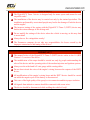
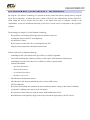
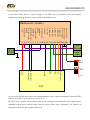
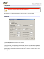
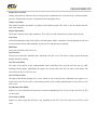
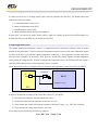
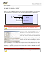
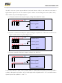
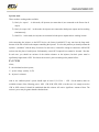
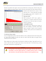
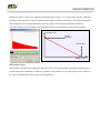
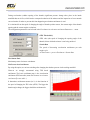
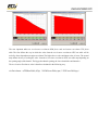
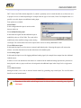
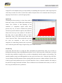
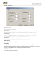
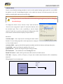
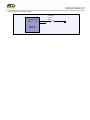
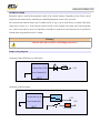
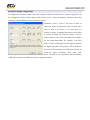
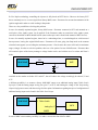
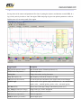
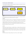
ATTENTION !
The Digital ECU Tuner 3 device is designed only for motor sports and cannot be used
on public roads!
The installation of the device may be carried out only by the trained specialists. The
installation performed by non-trained people may lead to the damage of both the device
and the engine!
The incorrect tuning of the engine with the Digital ECU Tuner 3 (DET3) device may
lead to the serious damage of the driving unit!
Do not modify the settings of the device when the vehicle is moving, as this may lead
to an accident!
Always have a fire extinguisher nearby!
The Ecumaster company do not take any responsibilities for losses caused by the
improper connection or/and tuning of the device!
IMPORTANT !
The manual below of the Digital ECU Tuner 3 (DET3) device refers to the 1.0 (HW
Version 1.0) version of the device.
The modification of the maps should be carried out only by people understanding the
rules of the device and the operating rules of the modern injection and ignition systems.
Always use the wide band A/F ratio gauge while creating tables.
Do not short circuit the wires of the engine’s wiring loom nor the outputs of the DET3
device.
All modifications of the engine’s wiring loom and the DET3 device should be carried
out while the negative pole of the battery is disconnected.
Take care of the high quality of the group’s wire connection and their proper isolation.
All signals from inductive sensors should be connected with screen wires.
The device should be disconnected while welding the vehicle’s body!
Table of contents
The installation of the software..................................................................................................................5
Connecting the device................................................................................................................................6
Configuration.............................................................................................................................................7
Sensors’ configuration................................................................................................................................9
Injectors....................................................................................................................................................12
Cranking...................................................................................................................................................15
Afterstart enrichment...............................................................................................................................16
Warmup enrichment.................................................................................................................................17
Acceleration enrichment..........................................................................................................................18
Narrowband O2 sensor (NGO)................................................................................................................20
Tables switch input...................................................................................................................................21
Boost control ...........................................................................................................................................22
Launch control ........................................................................................................................................25
Parametric output.....................................................................................................................................27
Factory MAP/MAF sensor.......................................................................................................................29
Log...........................................................................................................................................................30
Ignition control ........................................................................................................................................32
Work mode sequence of DET3 Fuel Implant...........................................................................................33
Speed Density algorithm..........................................................................................................................34
Alpha-N algorithm...................................................................................................................................35
ECUMASTER DET3 „FUEL IMPLANT” TECHNOLOGY
By using the „Fuel Implant” technology, it is possible to directly control the injectors opening time by using the
Speed Density algorithm. It enables the precise control of the fuel’s dose independently from the main ECU,
which brings the device’s actions closer to those of the Stand Alone type of computer. Thanks to the
‘implantation’ system, the installation and tuning of the device is much easier in comparison to the typical SA
computer.
The advantages of using the „SA Fuel Implant” technology
−
the possibility of controlling much bigger injectors than the serial ones,
−
avoiding the system of the ECU auto-adaptation,
−
user defined rev limiter,
−
the full control over the fuel’s dose, not disrupted by the ECU
−
using the factory temperature and shaft location sensors
Features of the SA Fuel Implant technology:
−
controlling the fuel’s dose based on the Speed Density or Alpha-N algorithm.
−
16x16 table describing the volumetric efficiency of the engine in the function of load and turn,
−
controlling the injectors in the Batch Fire or Bank Fire mode (2 injector banks)
−
mixtures enrichments:
−
After Start Enrichment,
−
Warm-up Enrichment,
−
Acceleration Enrichment
−
Barometric Correction
−
full calibration of temperature sensors,
−
full calibration of the absolute manifold pressure’s sensor (MAP sensor),
−
full TPS calibration,
−
the injector model taking into consideration injector dead time and the voltage on the electric installation,
−
„prime pulse” enabling easier start-up of the cold engine,
−
the correction of the fuel dose by using the narrow band lambda probe (EGO)
−
the modification of the ignition’s angle (in the respect towards the angle made by the ECU driver).
The installation of the software
In order to use the Fuel Implant technology you should install the right software for Windows and the
appropriate firmware of the device.
The software can be found on the CD included with the device or on the producer’s website
www.ecumaster.com. After installing the software, connect with the device and update its firmware
(File/Upgrade Firmware).
In order to restore the original DET3 software you should run the standard client and then load the right
firmware (File/Upgrade firmware).
Attention!
Disconnect the power of injectors before updating the software!
Connecting the device
On the Picture below there is a typical example of the DET3 device’s connection in the „Fuel Implant”
configuration with using the factory sensors and the external MAP sensor.
DIGITAL ECU TUNER 3
Power Out #1
Power Ground
Power Out #2
Analog Out
Analog In #4
Analog In #3
Analog In #2
Analog In #1
+5V Out
Ground
Frequency In
Ignition In
Pullup
Frequency Out
Ignition Out
Bipolar Ign. Out
Bip. Ign. Out Inv.
Pullup
Map Switch
+12V
1 2 3 4 5 6 7 8 9 10 11 12 13 14 15 16 17 18 19 20
MAF
SENSOR
CRANK
SENSOR
MAP
Sensor
Inj.
Bank 1
Inj.
Bank 2
MAF Sensor
IAT
CLT
TPS
Ground
Crank sensor
Crank sensor
+12V
+12V
ECU
As you can see from the above picture, the coolant temperature sensor , intake air temperature sensor and TPS is
common for the DET3 device and for the factory ECU.
The DET3 device modifies also the ignition angle (by the interception and modification of the signal from the
crankshaft position sensor) and the signal from the factory airflow meter. Additionally, the injectors are
connected in pairs to the power outputs of the device.
Configuration
Attention!
Disconnect all injectors before setup the configuration!
Basic parameters of the configuration of the device can be found in the SA Fuel Implant menu.
General setup
In the General setup menu we can define the basic parameters.
Enable Alpha-N
It activates the Alpha-N algorithm. In case of this algorithm, the engine load is defined only on the basis
of the TPS signal. This mode is useful for a car with the sport camshafts, where the stable intake
pressure is hard to maintain on idle speed.In case this option is unmarked, the device uses the Speed
Density algorithm.
Enable Baro correction
Turning this option on makes the device taking into the consideration the correction of the current barometric
pressure. The barometric pressure is read directly after starting the device.
Number of cylinders
This number describes the number of cylinder of the modified engine. This value is used to calculate the base
time of the injection.
Engine displacement
The engine’s capacity in the cubic centimetres. This value is used to evaluate the base time of the injection.
Load range
Values determining the range of the load for fuel and ignition tables. It should be selected optimally for the real
pressure measured in the intake manifold, in order to use as big table area as possible.
RPM Limit
Turns, above which the fuel dose is cut.
Fuel Cut above
The pressure in the intake manifold, above which the fuel dose is cut. This value is used to protect the engine
damage from the overboost.
Fuel Cut under (kPa)
The value of the pressure in the intake manifold, under which there may occur the fuel dose cut (eg. while
breaking with the engine). Additionally, the engine’s revs must be above the Fuel Cut Above value and the TPS
value below the Fuel cut TPS low limit.
Fuel cut TPS low limit
The angle of the throttle opening (in %), above which we can cut the fuel dose. Additionally, the engine’s revs
must be above the Fuel Cut Above value and the pressure value in intake manifold must be below the Fuel Cut
under value.
Fuel Resume below (RPM)
Engine revs, below which the fuel injection is resumed, independently of the Fuel Cut Under and Fuel cut TPS
low limit value.
Fuel cut above (RPM)
Engine revs, above which the fuel dose is cut, depending on the Fuel Cut Under and Fuel cut TPS low limit
value.
Sensors’ configuration
To make sure the device is working properly and it correctly calculates the fuel dose, you should connect and
calibrate the following sensors:
1) Coolant temperature sensor (CLT),
2) Intake air temperatur sensor (IAT),
3) Throttle position sensor (TPS),
4) Intake manifold absolute pressure sensor (MAP)
In most cases, you can use the engine factory sensors, which are currently present in the modified engine (codividing the sensors by the DET3 device and the factory ECU).
Coolant temperature sensor
The coolant temperature temperature sensor is a temperature-sensitive thermistor (element, which resistance
depends on the temperature). The most often used temperature-sensitive resistors used in the combustion engines
are those of the NTC type (with the negative temperature coefficient, i.e. the temperature increase leads to the
decrease of the resistance). In the factory ECU, there is a resistor (Rx), which together with the temperature
sensor, makes the voltage divider. In order to configure the temperature sensor, you should provide the resistor’s
value Rx and the characteristics of the temperature sensor’s resistance.
On the picture below, there is a diagram of the co-division of the temperature’s sensor by the ECU and DET3.
+5V
Rx
CLT Sensor
DET 3
Analog In #3 (15)
ECU
In order to calculate the resistance of the resistor Rx in the ECU, you should:
1) Disconnect the connector from the temperature sensor.
2) Check the voltage while the ignition is on and save it as Uin,
3) Then, connect the resistor of the known resistance in the sensor’s plug (e.g., 10K ) Rk ( in Ohms),
4) Then, measure the voltage again and save it as Uout
Rx resistance can be obtained by the following equation:
Rx = Rk * (Uin – Uout) / Uout
Sample calculations:
Uin = 4.94V, Uout = 4,05V, Rk
= 10000 (10K)
Rx = 10000 * (4.94 – 4.05)/4.05 = 2197 ohm
When you are using the additional temperature sensor, you should connect it to the DET3 device according to
the scheme below. The Rx resistor should be in the 2-4k7 range, depending on the sensor’s characteristics.
+5V
Rx
CLT Sensor
DET 3
Analog In #3 (15)
Attention !
The DET3 device works correctly only with the NTC type temperature sensors!
In order to configure the coolant temperatur sensor, you
should choose the Sensors option from the menu CLT sensor.
In the Rx field you should set the previously calculated Rx
resistor value. The sensor’s characteristics can be chosen from
the list of predefined sensors (Predefined sensors) or by
entering 3 temperature values with appropriate sensor’s
resistance. These values can be found in the service manual of
the vehicle or can be measured (e.g., for 0, 25 and 100 Celcius
degrees). Then, choose the Generate option, which will lead to generating the curve characteristics of the sensor.
The black line on the graph shows the characteristics of the sensor’s resistance, the red line show the voltage
characteristics of the voltage divider. If you insert the incorrect data, the graph won’t show any curves. Then,
you should correct the sensor’s characteristics.
Attention !
The correct sensors’ calibration is the key element of the proper work of the device!
Attention !
The sensors’ calibration doesn’t write down the settings in the device’s memory, it
only generates the calibration curve!
Intake air temperature sensor
Rules of connecting and calibrating the air temperature sensor are identical to those of the coolant temperature
sensor.
Attention !
Intake air temperature sensor (IAT) is the key sensor used to calculate the fuel dose,
that is why it cannot be ever omitted.
MAP sensor
In order to configure the absolute pressure sensor, you should
provide its measure range (maximal pressure with 5V), and the
offset (that is the minimal pressure indicated by the MAP sensor).
TPS
The proper calibration of the throttle position sensor is very
crucial from the point of view of the correct work of the device.
We should make sure that the values indicated by the TPS
location were 0% for the throttle closed and 100% for the full
throttle. The calibration takes place by inserting the proper value
for the minimal and maximal value indicated by TPS sensor. The
value 0 – corresponds to 0V, 128 – 2.5V and 255 – 5V.
Enable TPS Antiflood
This option activates the function of the fuel burning chamber ‘clearing’ during the start-up. If, during the
cranking period, the throttle is open above the 90%, the injection time is set to 0ms.
Injectors
The DET3 device has 2 power outputs with the 5A load each. Because of this, we can connect to each of them 4
high-resistance injectors or two low-resistance injectors with the resistor limiting the current (6Ohm, 25W+).
There are three ways of connecting the injectors:
1) All injectors connected to one power output, working in the „Batch Fire” mode
+12V
20 Power Out #1
19 Power ground
DET 3
2) Injectors are connected to both power outputs, working in the „Batch Fire”. This mode is used in case of
engines with the number of cylinders higher than 4.
+12V
20 Power Out #1
19 Power ground
+12V
18 Power Out #2
DET 3
3) Injectors connected to both power outputs, working in the „Bank Fire”
+12V
20 Power Out #1
19 Power ground
+12V
18 Power Out #2
DET 3
In case of the “Bank fire” mode, for the 4 cylinder engine we should connect the injectors in pairs from cylinder
working in the opposite cycle phase. And so, for the engine with the ignition order 1-3-4-2, we should connect
injectors in pairs from cylinders 1 - 4 and 3 - 2.
ATTENTION!
Exceeding the outputs’ load limit (5A) will lead to the damage of the power outputs,
what may cause the permanent opening of the connected injectors !
ATTENTION!
The line powering the injectors (+12V) should be protected with the suitable fuse and
the powering should take place only with the ignition being turned on !
ATTENTION!
The ground used to control the injectors (Power ground) should be a connected by
different wire than the one used to power the device (Ground pin 10).
The description of the parameters of the injectors’ configuration
The options of injectors’ configuration are available from the SA Fuel Implant/Injectors menu.
Injector Size
Injectors’ flow in cm3/min.
Injector opening time
The time required to open the injector in milliseconds, for the working
pressure and the powering voltage 13.5V. Usually, this is the value in the
range of 0.6-1.2ms.
Battery correction
The linear correction of injectors’ opening time, depending on the voltage
in the electric installation of the car, with regard to the voltage 13.5V.
Together with the decrease of the voltage, the opening time of injectors is extended.
Injection divider
This value stands for the frequency of fuel injection compared to the crank shaft turn.
The engine’s cycle (720 degrees of the crankshafts’ turn) is divided into 4 parts (every 180 degrees).
Divider which equals 1 in the Batch Fire mode means that all fuel injectors will be started every 180 degrees. In
case the injectors work in the Bank Fire mode, this will mean that each bank will inject the fuel once per 180
degrees of crank shaft turns.
In case it works in the Batch Fire mode, it is advised to use the divider which equals 2 or 4. In case it works in
the Bank Fire mode, it is advised to use the divider which equals 1or 2.
Injection mode
There are three working modes available:
1) Batch fire output 1 – in this mode, all injectors (not more than 4) are connected to the Power Out #1
output,
2) Batch fire output 1& 2 – in this mode, the injectors are connected to both power outputs and are working
simultaneously,
3) Bank Fire – in this mode, the injectors are connected to both power outputs and are working in turns.
After connecting the injectors to the DET3 device, the factory installed ECU may turn into the limp mode
because of the lack of load in the outputs controlling the injectors. To solve this problem you should perform the
injectors’ „emulation” with the help of resistors. In most cases, it should be enough to connect the 10K/0.25W
resistors into the place of each injector. Unfortunately, certain ECU output drivers cannot be “cheated “ like that.
In such case, you should use resistors of the similar resistance to the injectors, but their power must be
significantly higher than 0.25W. You choose the resistor’s power according to the pattern bellow:
P = U*U/R
where,
P – the calculated resistor’s power,
U – power voltage (usually 13,5V)
R – injector’s resistance
And so, the 14Ohm injector’s power should equal at least 13,5*13,5/14 = 13W. On the market, there are
available resistors of the following power: 10W, 15W, 20W, 25W, 50W, so in this case it is enough to use the
15W or 20W resistor. It should be underlined that this resistors will emit a significant amount of heat. The
resistor’s power may be greater that the calculated one.
Cranking
Parameters responsible for the engine’s start-up can be defined in the Cranking menu. The basic setting is the
injectors’ opening time during the engine’s start-up. This time can be defined in the 2D Cranking time table. It
should be noticed that this time is given in 1/10ms
units, that is 1ms = 10 unit in the table. The starting
dose depends on the engine’s temperature and it
grows with its decrease.
Prime pulse width
While powering the DET3 device (ignition is
switched on), it is possible to provide the extra fuel
dose (prime pulse), which may improve the engine’s
start-up by evaporating.
Cranking RPM threshold
The revs value, above whoch the device changes its
state from Cranking to Afterstart. Above these
engine’s revolutions, it begins to work by using the
volumetric efficiency table and all enrichments and
corrections.
Use both banks during cranking
In case of configuring the injectors to work in the Bank Fire mode, by marking this option in the Cranking mode,
the injectors during cranking will work in the Batch Fire mode, which may improve the engine’s start-up
(especially with low flow injectors).
While working in the Cranking mode, the fuel injection is realised twice during a single shaft’s turn. In case
when we choose the Bank Fire injection mode, and we do not choose the Use both banks during cranking
option, bank is started once for a single shaft’s turn.
Attention !
Too big values of the starting dose may lead to the engine flood and what follows is
the inability to start the engine until they are replaced. Because of that, we should
start from short value and extend them, until they reach the optimal start-up.
Afterstart enrichment
During the engine’s start-up the Afterstart Enrichment phase begins. It is in this phase that the additional
enrichment of the fuel dose in order to maintain stable engine revolutions, takes place. The enrichment depends
on the temperature of the liquid coolant (the cooler the engine is the stronger the enrichment should be).
A 2D table determines the percentage of enriching the fuel dose in the temperature function of the coolant.
Enrichment (%)
Starting
enrichment
ASE Duration
Engine cycles
ASE duration (cycles)
This parameter determines how long (how many full cycles will the engine make) should the enrichment last. It
is worth noting that enrichment is reduced in proportion to the number of cycles the engine works (it achieves
0% value by ASE duration) what is shown on the graph above.
Warmup enrichment
Enrichment of the fuel dose in the function
of
coolant
compensate
temperature
the
fact,
is
used
that
in
to
low
temperatures, the fuel doesn't vaporize well.
At
the
engine’s
enrichment
should
working
be
temperature
100%
(no
enrichment). In order of additional securing
of the engine from overheating you can
introduce small enrichment of the mixture
above the working temperature (additional
fuel can in many cases help to cool down
the engine).
Acceleration enrichment
During acceleration (sudden opening of the throttle) significant pressure change takes place in the intake
manifold thus an air flow, which leads to a temporal reduction of the mixture and the impression of a non smooth
car acceleration. In order to prevent this from happening acceleration enrichment is used.
It is calculated from the speed of changing the angle of throttle position sensor, the current angle of the throttle
opening and the current engine revolutions.
The configuration parameters can be found in the Enrichment/Acceleration enrichment/Parameters… menu.
dTPS Threshold(%)
dTPS value (the speed of changing the opening angle of the
throttle) below which the mixture is not being enriched.
Sustain Rate
The speed of decreasing acceleration enrichment per each
engine cycle.
AccEnrichment = prevAccEnrichment * Sustain Rate
Enrichment Limit
Maximum percent of mixture enrichment.
MAP sensor based enrichment
By using this option, we activate enriching after changing the absolute pressure in the sucking manifold.
However we strongly recommend using TPS based
enrichment. The basic enrichment map is the Acceleration
enrichment dTPS rate table (menu Enrichments/Acceleration
enrichment/Tps rate table...).
It determines enrichment amount (in %) in the function of
the speed of changing the TPS value (dTPS). The bigger the
throttle angle change, the bigger should the enrichment be.
The next important tables are Acceleration enrichment RPM factor and Acceleration enrichment TPS factor
table. The first defines the way in which the value from the Acceleration enrichment dTPS rate table will be
scaled by factor dependent on engine revolution. The higher the revs the enrichment value is lower. The second
map defines the way of scaling the value from the Acceleration enrichment dTPS rate table map depending on
the opening angle of the throttle. The bigger the throttle opening, the lower should the enrichment be.
The Acceleration Enrichment value is therefore calculated in the following way:
AccEnrichment = dTPSRateTable (dTps) * RPMFactorTable(rpm) * TPSFactorTable(tps)
Narrowband O2 sensor (NGO)
DET3 device has the possibility to change the contents the mixture on the basis of readings from the narrowband
O2 sensor (NGO). For the 0.45V voltage sensor reads
stoichiometric mixture (Lambda=1). Thanks to this in the
scope of low engine load, it is possible to correct the
mixture, to reach the stoichiometric composition. The
Lambda probe should be connected to the Tables Switch
(pin 2) input of the device, after having changed its function
in the Tables switch input menu to Use as NBO sensor
input. Next in the EGO Correction configuration can be
made. The following parameters are available:
Target Voltage(V)
The target voltage of the oxygen sensor, which DET3
device will try to achive
Control range(%)
The allowed change of the fuel dose described in percent.
Change step(%)
The step by which the mixture change is made.
Change rate
Parameter describing how often should the algorithm change the value of the correction of the dose. Value 1
means that during each fuel injection, value 2 that every 2 injections, and so on.
Coolant temp.(C)
Temperature, below which the correction of the mixture’s is disabled.
MAP Max (kpa)
Pressure in the intake manifold, above which the fuel dose correction is disabled.
TPS Max (%)
The value of the throttle position, above which the fuel dose correction disabled.
RPM min
Parameter describes the minimal engine revolutions, above which the correction of fuel dose is active.
RPM max
Parameter describes the engine revolutions above which the fuel dose correction is disabled.
Tables switch input
DET 3 device has Tables Switch Input (Pin 2), which is primarily used to switch the table set (it allows the user
to prepare two sets of tables depending for example from the type of fuel used). In the Fuel Implant mode it is
possible to use this input as an additional analog input.
Four options are available:
Switch Tables
In this configuration the input is used to switch
between table sets
Use as modified analog input
In this mode the signal from the additional input is
modified by the use of Fuel Table. The result of this
modification is the modified voltage on the Analog
Out output. You can find more info on this option in the section on factory MAP/MAF sensor.
Use as NBO sensor input
In this mode the input is used to connect a narrow band lambda probe. Selecting this option will activate the
mixture correction function based on the indications of the lambda probe.
Use as analog input
In this mode the input is used for logging additional analog signal (for example linear output from the wideband
lambda sensor).
In order to receive the indications from the device connected to the additional analog input that are presented in
their physical values, a proper scale has to be assigned to the additional input in the Setup/Scales configuration
menu.
Use as launch control
Setting this mode, user is able to activate launch controll by grounding map switch input. You can find more
details in section launch control.
Important !
Function of the table switch input must be chosen before connecting any signal to
this input.
Boost control
Using DET3 in Fuel Implant mode gives the possibility of controlling the boost pressure both in open loop and
closed loop. In order to be able to use the boost control all injectors have to be connected into the first power
output (pin 20 of the device, work in full group mode).
Open Loop
Controlling the boost pressure in Open Loop mode is
based only on duty cycle of PWM signal controlling the
electric valve. Because of that depending on the
conditions (i.e. temperature, engines strain) boost
pressure may vary. In order to eliminate this problem
Closed Loop control should be applied (with feedback).
However the first step is the creation of a 2D table of
base duty cycle at given RPM in order to receive
approximate values of the desired boost (menu Boost
control / Boost DC Table). Values on this table vary from
0% (valve not energized) to 100% (valve fully
energized). It is worth noting, that due to the way electric
valves work the typical usable range of signal’s duty cycle is from 15% to 85% .
Closed Loop
At the time when the boost is set with DC Table corresponds the expected boost values, one can move to
defining the boost map (in kpa) in the RPM function (Boost control / Boost target table). In this table, we present
the desired boost which the controller will try to achieve independently from the engines work conditions. The
controller modifies, based on the PID algorithm, the duty cycle of the electro valve, defined in Boost DC Table.
Correct defining of the PID parameters allows acquiring stable boost pressure without oscillation. First the value
of the P (proportional) parameter has to be set (I and D should be set to 0), so that the controller will closing on
the desired boost target with small oscillation. Those oscillations can be eliminated with correctly set values of
the I (integral) and D (derivative) parameters.
Parameter description
Enable boost control
Activates boost control functionality.
Max Overboost
Maximum pressure allowed in kPa. Above this value the controller sets DC of the electric valve to 0%.
PWM Frequency
Frequency of the signal controlling the valve. Depending on the valve, the frequency can be 10-100Hz.
Correct setting of PWM frequency results in optimal work of the electric valve.
Max, Min DC
Minimum and maximum duty cycle of the signal by which the valve works stable.
Disable under kPa
Pressure below which the valve is disabled.
Invert output
Invert duty cycle of the valve (used with valves connected the other way out where 0% DC gives the maximum
boost). Such connection is not advised, because in case of damaging the device, electric harness or electric valve
will lead to overboost which can result in damaging the engine and/or turbocharger.
Closed loop control
Activates the control option in closed loop
P, I, D
Controllers PID factors (kP, kI, kD), determining how “strong” influence has each of the regulators members.
Integral windup
Maximum saturation of integral element of PID regulator.
Feedback +,Maximum and minimum values by which can the PID algorithm change the DC of the electric valve defined in
the Boost DC Table.
Diagram of connecting the electric valve
Connecting the electric valve should look as follows:
Power Out #2 (18)
+12V
Power Ground (19)
Electrovalve
DET 3
The diagram below presents the method of connecting the three way valve used for controlling the boost of
turbochargers with an internal wastegate.
To wastgate
DET 3, PIN 18
2
3 Way Vale
Bleed
3
Boost
1
+12V
The presented valve is opened between the stubs 2-3 if it is unpowered. In case of powering the connection
between stub 1-2 is open.
For the above mentioned connection 0% of duty cycle gives minimal boost defined by the actuator, 100% of dc
causes maximum boost that can be achieved by the turbocharger.
Launch control
Launch control function (starting procedure) is used to set the optimal starting engine speed (for a given RPM
the ignition is cut off). In turbocharged engines, it also enables the increase of the boost pressure at the start
thanks to retarded ignition and an increased fuel dose.
Caution !
Using the launch control function in the turbocharged engines may lead to damaging
the turbocharger.
To configure the launch control, enter the “Setup” menu and choose
“Launch control configuration” option. To activate the function, select
the activation input. There is also a possibility to turn the launch
control off, when the car speed is greater than the defined value (VSS
sensor must be connected to the Frequency In input of DET 3).
Parameters:
Activation input – what input used for activating the launch control
function. For extra analog input table switch input must be configured
as “Use as launch control”
Activation. RPM – engine speed which the ignition retardation and the fuel mixture enrichment takes place,
Cut off RPM – engine speed when the ignition will be cut off,
Ignition Retard – ignition retard angle during the staring procedure,
Fuel Enrichment – value added to the current Analog Out value.
Enable VSS control – enable vehicle speed sensor (VSS) control over launch control,
VSS Limit – frequency (in Hz) of Frequency In input, above launch control function will be automatically
turned off.
Wiring diagram for extra analog input:
Activation
Switch
(SW1)
Map switch(3)
DET 3
Wiring diagram for frequency input:
Frequency In(10)
Pullup
(8)
DET 3
Activation
Switch
(SW1)
Parametric output
Parametric output is used for the parametric control of the external actuators. Depending on the electric current
required by the actuator, direct controlling or controlling through an electric relay is possible.
The current drawn from the Power Out #2 cannot exceed 5A (eg. it can be used directly to control LED diode,
electrovalves, buzzer, etc.), .If the required current exceeds 5A (for example, fuel pump, water injection pump,
etc.), electric relay must be used. It is important to remember to connect an extra Ground to the 19 pin (Power
Ground) when using the Power Out #2 output.
Warning !
Current draw that exceeds 5A will damage the device!
Sample wiring diagrams
Connection of the LED diode (eg. Shift Light)
Power Out #2 (18)
330R
+12V
Power Ground (19)
DET 3
Connection of the fuel pump
Power Out #2 (18)
+12V
+12V
Power Ground (19)
DET 3
Fuel Pump
Parametric output configuration
To configure the parametric output, choose the parameter window (Setup/Paramteric output configuration). In
the configuration window, choose inputs, which will be used as function parameters, referential values and
conditions, which fulfillment will activate the user output.
Parameters Source1, Source2 and Source3 allow to
choose the inputs. If interested in only one input, chose
None as Source2 and Source 3. For each input it is
possible to choose a condition that needs to be fulfilled
to activate an output. The Hysteresis (Hist.) is used to
define hysteresis value. This value defines the condition
for the output deactivation. For example, if the LED
diode is used as a shift light when the engine revolutions
are higher than 5000, and hysteresis will be defined at
the level of 500 revolutions, the LED diode will turn off
when the engine revolutions drops under 4500.
Additionally, between the conditions for the Source1, Source 2 and Source3, it is possible to define a condition
(AND, OR) which must be fulfilled to activate a parametric output.
Factory MAP/MAF sensor
In Fuel Implant technology controlling the injectors is fully based on DET3 device. However the factory ECU
has to constantly receive a correct signal from factory MAP sensor / flowmeter for accurate determination of the
ignition angle and in order to avoid working in limp mode.
There are a few possibilities of solving this problem.
In case of a naturally aspirated engines, factory MAP sensor / flowmeter connected to ECU and mounted on a
serial place of the intake system, can be applied. If the flowmeter makes an restriction in the intake system,
conversion from MAF to MAP should be done (more on the topic can be found in the manual of DET3 device).
In case of a naturally aspirated engines, altered to be a turbocharged one, or a turbocharged car with increased
boost pressure, leaving the original MAP sensor / flowmeter will cause going into limp mode at the moment
when the boost appears (or exceeding the maximum pressure / flow) because the sensor will reach its maximum
range (voltage). In order to solve this problem, there are a few options. In case of MAP sensor / flowmeter that
will remain in place of the factory montage a voltage limiter can be used with the use of a resistor and Zener’s
diode:
10K
MAF/MAP
ECU
4V7
Available on the market are diodes 4V3 and 4V7, that will reduce the voltage accordingly do about 4,3V and
4,7V.
A different possibility is to connect a factory MAP/MAF sensor to an additional analog input ( Tables Switch
Input pin 2) and the analog output Analog Out (pin 17) to ECU and limiting the voltage in the Setup/Analog
Output Configuration menu with the Analog Out Max option. Information regarding the topic of configuration of
additional analog input can be found in the Tables Switch Input.
MAF/MAP
2 Tables Switch
Analog Out 17
ECU
DET3
In case of MAF sensor another possibility is to make a conversion from MAF to MAP.
Log
Saving values of the sensors and parameters like time of opening the injectors, enrichments or actual RPM, in a
log is an key activity in order to “tune” the engine. While analyzing a log one can optimize parameters / tables or
find the cause of a not correct work of the engine.
Logged signal
Description
TPS (Throttle position sensor)
Value from the sensor of throttle position (in %)
CLT(Coolant temperature)
Coolant temperature
Analog Out
Voltage value on the Analog Out output
Freq. In(Frequency in)
Input frequency in Hz on the Frequency In input
ASE(Afterstart Enrichment)
The current Afterstart enrichment value (100% means no enrichment)
Ignition Angle
Current value of the ignition angle modification (0 – no modification,
negative value – retarded ignition, positive value – advanced ignition
TPS Rate(dTPS)
Current value of the angle change of the throttle position (%/s)
Acc. Voltage(Accumulator Voltage)
Voltage in the car’s electric installation
MAP(Manifold absolute pressure)
Absolute manifold pressure (in kPa)
IAT(Intake air temperature)
Intake air temperatur
RPM(Revolutions per minute)
Current engine speed
Freq. Out (Frequency Out)
Current frequency in Hz on Frequency Out output
Injection Out
Time of opening of the injectors in ms
Warmup(warmup enrichment)
Value of enrichment of the mixture in the function of coolant temperature
Acc.enrich.(Acceleration enrichment)
Current value of acceleration enrichment
Ign. Error(Ignition error)
Error of decoding signal from the crank / cam sensor
Analog In
Value of the additional analog signal from Tables Switch input (pin2)
NBO Corr. (Narrow band oxygen Fuel dose correction value based on the readings from narrowband
sensor correction)
lambda sensor
Ignition control
Ignition control is made analogically to the standard mode of the devices work. More information on this topic
can be found in the DET3 manual.
Work mode sequence of DET3 Fuel Implant
Current working mode of DET3 Fuel Implant is displayed on the Windows client status bar. The device
can be running in one of the following modes:
RPM > RPM Threshold
Inactive
RPM > 50
Cranking
Afterstart
Engine cycles > ASE cycles
Running
Inactive
In this mode the device awaits signals from the crank/cam sensor. The time of opening the injectors is
0ms. Readings from all sensors connected with the device are possible.
Cranking
The device moves from Inactive mode to the Cranking mode, if engine speed exceed 50 revolution
per minute. In Cranking mode the fuel dose is defined by the Cranking time table table in the
temperature function (Cranking menu). If, in TPS configuration the Enable TPS Antiflood option is
enabled and the throttle is open in more than 90% then the time of opening the injectors is 0ms.
If the engine rotation exceeds the value of Cranking RPM threshold , the device goes in Afterstart mode. If the
RPM go below 50 the device returns to Inactive mode.
Afterstart
During Afterstart mode the fuel dose is calculated based on a volumetric efficiency table and all
corrections and enrichments. Additionally Afterstart enrichment is active. It is active for the whole time
defined by the number of engine’s work cycles ASE duration (in engine cycles), after this time engine
goes into Running mode. In Afterstart mode correction using the narrow band oxygen sensor is
disabled.
Running
In this mode the engine is working according to the Speed Density or Alpha-N algorithm.
Speed Density algorithm
In Speed Density algorithm the injector opening time is calculated based on a physical model using absolute
pressure in the manifold, volumetric efficiency of the engine under given load, engine speed and the temperature
of the intake air that affects its density.
Volumetric efficiency table is a parameter that is subject to modifications during the engines tuning and is
defined on the VE Table map. The basic formula used to calculate the time of opening the injectors (in ms) looks
the following way:
PW = INJ_CONST * VE(map,rpm) * MAP * AirDensity,
where:
PW (Pulse width) – is the time of opening the injectors in ms
INJ_CONST – It is a constant dependent on the engine’s capacity, size of the injectors and the Injection Divider
parameter, it represents the time of opening the injectors in order to receive stechiometric mixture by 100%
engines volumetric efficiency, 100Kpa pressure and 21C temperature.
VE(map, rpm) – Is the value from volumetric engine’s efficiency table in percent.
MAP (Manifold absolute pressure) – absolute pressure in the manifold,
Air Density – Percentage difference of air density against air density in temperature 21C.
Additionally the time of opening the injectors is based on corrections and enrichments. Due to that fact the total
formula for calculating the injector’s opening time looks the following way:
PW = INJ_CONST * VE(map,rpm) * MAP * AirDensity * Baro * Warmup * ASE * EGOCorr * AccEnrich +
InjOpeningTime,
where:
Baro(Barometric correction) – correction of absolute pressure against barometric pressure
Warmup(Warmup enrichment) – value of enrichment of the mixture in the function of cooling liquid temperature
ASE(Afterstart enrichment) – current value of Afterstart enrichment in %
EGOCorr(Exhaust gas oxgen sensor correction) - correction value of the fuel dose based on the narrowband
lambda sensor in percent.
AccErich(Acceleration enrichment) - current value of in acceleration enrichment described in %.
InjOpeningTime (Injectors opening time) – injectors dead time in ms, corrected by the voltage value of the car’s
electric installation.
Alpha-N algorithm
Algorithm Alpha-N is similar to Speed Density algorithm, however the pressure in the manifold is not taken into
account, additionally the engine load is described by the opening of the throttle.
Alpha-N mode cannot therefore be used in turbocharged cars!
The formula for calculating the injector’s opening time looks the following way:
PW = INJ_CONST * VE(tps, rpm) * AirDensity * Baro * Warmup * ASE * EGOCorr * AccEnrich +
InjOpeningTime,
where,
PW (Pulse width) – is the time of opening the injectors in ms
INJ_CONST – It is a constant dependent on the engine’s capacity, size of the injectors and the Injection Divider
parameter, it represents the time of opening the injectors in order to receive stoichiometric mixture in 100%
engines volumetric efficiency, 100Kpa pressure and 21C temperature.
VE(tps, rpm) – Is the value from volumetric engine’s efficiency map displayed in percent.
Air Density – Percentage difference of air density against air density in temperature 21C.
Baro(Barometric correction) – correction of absolute pressure against barometric pressure
Warmup(Warmup enrichment) - Value of enrichment of the mixture in the function of cooling liquid temperature
ASE(Afterstart enrichment) – current value of Afterstart enrichment in %
EGOCorr(Exhaust gas oxgen sensor correction) - Correction value of the fuel dose based on the narrowband
lambda sensor is disabled.
AccErich(Acceleration enrichment) - Current value of acceleration enrichment described in %
InjOpeningTime (Injectors opening time) – injectors dead time in ms, corrected by the voltage value of the car’s
electric installation.