1
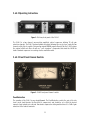
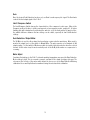
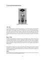
Model 2-LA-2
Twin T4
Leveling Amplifier
Universal Audio Manual Number 65-1601
Revision 2.01/WS
i
2-LA-2 Twin T4 Leveling Amplifier
Thank you for purchasing the 2-LA-2 Twin T4 Leveling Amplifier. The 2-LA-2 Takes the best our UA
Classics LA-2A reproduction and updates it with modern features, modern components, and a spacesaving design. The original LA-2A was designed by Jim Lawrence and produced in the early 1960s by
Teletronix, which was later acquired by Babcock Electronics Corporation. Bill Putnam purchased the
design and the name Teletronix from Babcock Engineering in 1967, folding it into his Studio
Electronics Corporation. Straightforward in its design, and initially intended for broadcast
applications, the LA-2A quickly became standard equipment in studios worldwide.
Still a class A, tube-amplified, all discrete design, the 2-LA-2 retains the same key gain reduction
components and simple controls, but adds the modern convenience of a stereo matched tool made
more versatile for modern studios. As with all optical compressors, the 2-LA-2 works by applying the
audio signal to an electro-luminescent light panel which shines on a photo-electric cell which in turn
controls the gain. The cadmium-sulfide photo-cells provide a very natural “two-stage, “program
dependent” release which results in a very transparent compression characteristic. The 2-LA-2
delivers the same trademark sound of the LA-2A treasured by engineers worldwide.
Features
•
Sound and circuit of the original Teletronix LA-2A
•
Matched optical T4 modules
•
Linked stereo or dual mono operation
•
2U Rack, Custom UA transformers, audiophile components
•
Designed by original UREI® engineer Dennis Fink
In addition to the 2-LA-2, Universal Audio has released reproductions of the classic Teletronix LA-2A
Leveling Amplifier, LA-3A Audio Leveler and 1176LN Limiting Amplifier as well as the 610 tube preamp
series of products which are based on those used in the legendary Bill Putnam custom consoles.
Modern tools such as the flagship 4110 & 8110 Precision Class-A solid-state microphone
preamplifiers bring tonal flexibility to the multi-channel mic preamp. Universal Audio also creates
software emulations of vintage hardware and innovative mixing tools that run on our UAD DSP
platform. All of these products are designed to meet the demands of the modern recording studio, yet
retain the character and quality of vintage equipment. See more at www.uaudio.com, including the
award winning 6176 channel strip, the LA-610 all-tube channel strip, SOLO mic pre series, and 2192
Master Audio Interface A/D and D/A.
ii
IMPORTANT SAFETY INSTRUCTIONS
Before using this unit, be sure to carefully read the applicable items of these operating instructions
and the safety suggestions. Afterwards keep them handy for future reference. Take special care to
follow the warnings indicated on the unit, as well as in the operating instructions.
1. Water and Moisture – Do not use the unit near any source of water or in excessively moist
environments.
2. Object and Liquid Entry – Care should be taken so that objects do not fall, and liquids are not
spilled, into the enclosure through openings.
3. Ventilation – When installing the unit in a rack or any other location, be sure there is adequate
ventilation. Improper ventilation will cause overheating, and can damage the unit.
4. Heat – The unit should be situated away from heat sources, or other equipment that produce heat.
5. Power Sources – The unit should be connected to a power supply only of the type described in the
operating instructions, or as marked on the unit.
6. Power Cord Protection – AC power supply cords should be routed so that they are not likely to be
walked on or pinched by items placed upon or against them. Pay particular attention to cords at
plugs, convenience receptacles, and the point where they exit from the unit. Never take hold of the
plug or cord if your hand is wet. Always grasp the plug body when connecting or disconnecting it.
7. Grounding of the Plug – This unit is equipped with a 3-wire grounding type plug, a plug having a
third (grounding) pin. This plug will only fit into a grounding-type power outlet. This is a safety
feature. If you are unable to insert the plug into the outlet, contact your electrician to replace your
obsolete outlet. Do not defeat the purpose of the grounding-type plug.
8. Cleaning – The unit should be cleaned only as recommended by the manufacturer.
9. Nonuse Periods – The AC power supply cord of the unit should be unplugged from the AC outlet
when left unused for a long period of time.
10. Damage Requiring Service – The unit should be serviced by a qualified service personnel when:
a. The AC power supply cord or the plug has been damaged: or
b. Objects have fallen or liquid has been spilled into the unit; or
c. The unit has been exposed to rain; or
d. The unit does not operate normally or exhibits a marked change in performance;
or
e. The unit has been dropped, or the enclosure damaged.
11. Servicing – The user should not attempt to service the unit beyond that described in the
operating instructions. All other servicing should be referred to qualified service personnel.
iii
Notice
This manual provides general information, preparation for use, installation and operating instructions
for Universal Audio’s 2-LA-2.
The information contained in this manual is subject to change without notice. Universal Audio, Inc.
makes no warranties of any kind with regard to this manual, including, but not limited to, the implied
warranties of merchantability and fitness for a particular purpose. Universal Audio, Inc. shall not be
liable for errors contained herein or direct, indirect, special, incidental, or consequential damages in
connection with the furnishing, performance, or use of this material.
Contents
This package should contain:
2-LA-2 Twin T4 Leveling Amplifier
2-LA-2 Manual
IEC Power Cable
Product Registration Card
Warranty
Warranty for the 2-LA-2 and all Universal Audio hardware is one year, parts and labor.
Copyright
© 2007 Universal Audio, Inc. All rights reserved.
This manual and any associated software, artwork, product designs, and design concepts are subject
to copyright protection. No part of this document may be reproduced, in any form, without prior written
permission of Universal Audio, Inc.
Trademarks
2-LA-2, LA-2A, LA-3A, 1176LN, 2-610, 6176, LA-610, 4110, 8110, 2192, UAD and the Universal Audio,
Inc. logo are trademarks of Universal Audio, Inc. Other company and product names mentioned herein
are trademarks of their respective companies.
iv
Table Of Contents
Performance and Audio Specifications.................................................................................................... 5
2-LA-2 Operating Instructions................................................................................................................. 2
2-LA-2 Front Panel Channel Controls ...................................................................................................... 2
Peak Reduction ................................................................................................................................... 5
Gain .................................................................................................................................................... 3
Limit / Compress Switch ..................................................................................................................... 3
Gain Reduction / Output Meter............................................................................................................ 3
Meter Adjust........................................................................................................................................ 3
2-LA-2 Front Panel Global Controls ......................................................................................................... 4
Link / Dual........................................................................................................................................... 4
Bypass / Comp.................................................................................................................................... 4
Power .................................................................................................................................................. 5
Rear Panel Connections........................................................................................................................... 5
Input / Output ..................................................................................................................................... 5
Internal Voltage Selector..................................................................................................................... 5
Side-Chain Circuit .............................................................................................................................. 6
AC Power ............................................................................................................................................. 6
Fuse / Mains / Bulbs ........................................................................................................................... 6
Appendixes .............................................................................................................................................. 7
Compressor Basics ............................................................................................................................. 7
Gain Reduction Circuit...................................................................................................................... 10
Sidechain Circuit .............................................................................................................................. 12
Output Circuit ................................................................................................................................... 13
Metering Circuit ................................................................................................................................ 13
Historical Notes ..................................................................................................................................... 14
The 610 Preamp................................................................................................................................ 13
The 1176LN Limiting Amplifier and LA-2A Leveling Amplifier........................................................... 15
The 1176 LN ...................................................................................................................................... 15
The LA-2A.......................................................................................................................................... 16
Performance and Audio Specifications
v
Gain Reduction
Up to 40 dB
Maximum Gain
35 +/- 1dB
Attack Time
10 ms
Release Time
0.06 for 50% release; .5 to 5 seconds for complete release
Frequency Response
30 Hz to 15 kHz +/- .1 dB
Signal to Noise
-70 dBu
Distortion
Less than 0.35% at +10 dBm, and less than 0.75% at +16 dBm
Output Level
+20dBu nominal, @ 1%
Input Level
+24 dBu maximum
Input Impedance
600 ohms balanced
Output Impedance
600 ohms balanced
Tube Complement
(2) 12AX7A, (1) 12BH7A, (1) EL84 per channel
Fuses
115V usage-1.6 A / 230V usage: 800 mA
Power Requirements
110V/220V/100V
Power Consumption
80 watts
Dimensions
19”W x 3.5”H x 12.25”D
2-LA-2 Weight
14.5 lbs.
1
2-LA-2 Operating Instructions
Figure 1: Full view, front panel of the 2-LA-2
The 2-LA-2 is a two channel, vacuum tube amplified, optical compressor utilizing T4 cell gain
reduction elements. The 2-LA-2 features linkable sidechains allowing the user to stereo couple the two
channels at the flip of a switch. Designed by original UREI® engineer Dennis Fink, the 2-LA-2 retains
the original all-discrete Class A and core "sonic signature" components that made the LA-2A the
studio standard compressor in recording studios around the world.
2-LA-2 Front Panel Channel Controls
Figure 2: 2-LA-2 front panel channel controls
Peak Reduction
The operation of the 2-LA-2 is very straightforward. The Peak Reduction controls the gain of the side
chain circuit (and therefore the threshold of compression) and should be set so that the desired
amount of gain reduction is achieved. A moderate compression setting would achieve 3 to 5 dB of gain
reduction on the loudest transients.
2
Gain
Once the desired Peak Reduction has been set, use Gain to make up any lost signal. The Gain knob
controls the final output signal of the 2-LA-2.
Limit / Compress Switch
The Limit/Compress Switch changes the characteristics of the compressor’s ratio curve. When in the
Compress position, the knee is gentler, and presents a low compression ratio, roughly 3:1. A higher
limiting ratio with a harder knee results when the switch is set to the Limit position. In practical use,
the audible difference between the two settings can be subtle, especially at low Peak Reduction
settings.
Gain Reduction / Output Meter
The VU Meter is used for either output level monitoring or gain reduction monitoring. When used to
monitor the output level, set the switch to Output Meter. The meter operates at a standard +4 dB
output reading. Set the switch to GR when you wish to view the total gain reduction from the selected
channel. In this meter view, the meter normally rests at the 0 dB position when no compression is
occurring.
Meter Adjust
Sometimes fluctuations in the 2-LA-2’s internal operating temperature may cause the Gain Reduction
Meter settings to drift. This is a normal occurrence, and part of the charm of vintage style gear. The
setscrew on the left side of the meter switch allows the user access to the Gain Reduction Metering
calibration. Use a small tip flathead screwdriver to bring the meter back into calibration.
3
2-LA-2 Front Panel Global Controls
Figure 3: Front panel global controls
Link / Dual
Use the Link/Dual switch to easily go between dual mono or stereo linked operation. The Dual position
allows the two channels of the 2-LA-2 complete independence from each other. In this position, the 2LA-2 operates as two separate compressors. The Link position achieves a linked sidechain, which
causes both channels of the 2-LA-2 to compress on both sides evenly, specifically in the event of loud
transient activity on only one channel. The T4 gain reduction cells have been carefully matched to
allow the attack and release times of the two channels smooth and musical operation in stereo linked
use.
Bypass / Comp
The Bypass/Comp (Compression) switch allows the user the ability to toggle the gain reduction circuit
in or out of the audio path. This is useful in comparing the compressed signal to the non-compressed
signal with the flip of a switch. This is also useful if the user wishes to use the 2-LA-2 as an amplifier
only, for extra gain or tube coloration without the compression circuit in the signal path. The
Bypass/Comp switch is global, and affects both channels of the 2-LA-2, regardless of the Link/Dual
switch position.
Note: The Bypass function of the 2-LA-2 does not work in the modern sense; it will not recall gain
structuring to its original non-compressed position. Therefore, the Bypass position become less
practical in extreme gain reduction settings where large fluctuations in gain will occur between the
Comp and Bypass positions.
Power
The 2-LA-2 provides the user with a front panel power switch. It is recommended to power off the unit
when the 2-LA-2 is not used for extended periods of time.
4
Rear Panel Connections
The rear panel has two identical channels each with Line Input and Line Output connectors. The rear
panel also has an AC Power input with a fuse holder. These connectors and controls are discussed in
the following sections.
Figure 4: Full view, rear panel of the 2-LA-2
Input / Output
Standard XLR input and output connectors are provided on the rear panel. Pin 2 is wired positive (hot)
on the Line Input, and on the Line Output.
Figure 5: Line level XLR input and output connections
Internal Voltage Selector
The 2-LA-2 can operate at 110V, 220V or 100V. To change the mode, wait 5 minutes after power down,
unplug the AC power cord from the rear chassis. Remove the top cover. As shown in Figure 5, there is
a connector that can be plugged in to one location or another location to configure the unit for 110V or
220V operation. This figure shows the unit configured for 110V operation. The connector is part of the
wiring that comes from the power transformer located at rear center of the 2-LA-2.
When changing operating voltage, fuse value must be changed as well. Make sure the 2-LA-2 is
properly set for the voltage in your area before applying AC power to the unit! Failure to do so may
damage the unit.
5
Figure 5: Operating Voltage Selector
AC Power
The 2-LA-2 uses a standard, detachable IEC power cable.
Fuse / Mains / Bulbs
The AC power fuse is located in the AC power connector block. Remove the power cord before checking
or changing the fuse.
A 1.6 A time delay (slow blow) fuse is required for operation at 115 V.
A 800 mA time delay (slow blow) fuse is required for operation at 230 V.
A 6.3 V bulb (1847) is used for the power indicator light.
6
Appendixes
Compressor Basics
Before we dig in to a description of the LA-2A/2-LA-2 circuit, it is useful to examine the general
characteristics of compressors and review some terminology. Figure 1 depicts the input/output
characteristics of a compressor, an expander and a perfect amplifier. When operated within its
specified range, an amplifier provides a constant amount of gain regardless of the level of the input
signal. In Figure 1, the middle line depicts a perfect amplifier with a gain of 10 dB. To see this, notice
that a signal with an input level of –30 dB will result in an output level of –20 dB, which is an
increase of 10 dB. Similarly, an input level of 0 dB will result in an output level of 10 dB, hence the
gain stays fixed at 10 dB regardless of the input level.
Expansion
Perf ect Amplifier
+10
Compression
0
Output Level
(dB)
-10
-20
-30
-30
-20
-10
0
+10
Input Level (dB)
Figure 1: Input/output characteristics of a compressor, an expander and a perfect amplifier.
In contrast to an amplifier, whose job is to present a constant gain, a compressor varies its gain in
response to the level of the input signal. Large input signals result in less gain, thus reducing or
“compressing” the dynamic range of the signal. Referring again to the line marked “compression” in
Figure 1, we see that an input level of –30 dB results in an output level of –20 dB, indicating a gain of
10 dB. Repeating this for input levels of –20 dB and –10 dB, we see that the compressor exhibits
gains of 5 dB and 0 dB respectively. From this, it is clear that the gain decreases as the input signal
increases.
Referring to the diagram, we see that the compressor will increase its output level by 5 dB for every 10
dB that we increase the input level. The compression ratio is defined as the ratio of these two
numbers. In this case the compression ratio would be 10:5, which can be reduced to 2:1.
As an aside, an expander is a device which increases the dynamic range of a signal. For example, a
10dB change in the input signal might result in a 20 dB change in the output signal, thus
“expanding” the dynamic range.
7
There are several other terms related to compression that can be demonstrated by referring to Figure 2.
The amount of compression or gain reduction is typically given in dB and is defined as the amount by
which the signal level is reduced by the compressor. Graphically, this can be understood by looking at
the difference in levels between what would have been the uncompressed (the output from an
amplifier) output level and the compressed output level. This value is what the LA-2A meter displays
when it is switched to gain-reduction mode.
As mentioned previously, the compression ratio is defined as the ratio of the increase of the level of the
input signal to the increase in the level of the output signal. In this example, the input level is
increased by 10 dB while the output level only increases 5 dB. This would be a compression ratio of
2:1. Lower ratios such as 2:1 result in more gentle compression. (Note that a compression ratio of 1:1
is no compression at all).
Typically, compressors let you choose a threshold. This is the point at which gain reduction starts to
take place. When an audio signal is below this threshold the compressor acts like an amplifier and
there is no gain reduction. Above the threshold the slope becomes less than 45 degrees, indicating
gain reduction and hence compression.
The point at which a compressor transitions into compression is commonly called the knee. In
practical compressors, this transition is gentler than what is depicted in the diagram.
Many modern compressors provide a control which adjusts the threshold directly. In the case of the
LA-2A, the Peak Reduction knob controls both the threshold and the amount of compression.
Compression Region
10 dB of
Compression
+10
0
Output
Level (dB)
2:1 Compression
-10
-20
Knee
-30
-30
-20
-10
0
+10
Input Level (dB)
Figure 2: Input/output curve of a compressor with a ratio of 2:1 and a threshold of -20 dB.
8
Figure 3: Block diagram of the LA-2A compressor
9
A functional block diagram of the LA-2A is provided in Figure 3. A brief overview of the operation will
be provided here. The input transformer provides isolation and impedance matching. After this the
signal is fed into both the side-chain circuit and the gain reduction circuit. The side-chain is
comprised of a voltage amplifier, a pre-emphasis filter, and a driver stage, which provides the voltage
necessary to drive the electro-luminescent panel. This signal controls the gain of the compressor.
After the gain reduction circuit, the signal is sent through an Output Gain control and a two-stage
output amplifier, followed by the output transformer.
Electro-Luminescent
Panel
Photo-Electr ic Cell
Figure 4: Diagram of the T4 electro-optical cell
Gain Reduction Circuit
As mentioned previously, compressors are devices that vary their gain in a manner that is dependent
upon the level of the input signal. In order to do this, the compressor must first have some method of
determining the level of the signal, and must then be able to use this to control the gain. There are
many different schemes to accomplish these tasks. In the case of the LA-2A, both of these functions
are performed by the T4, which is an electro-optical element.
A T4 is comprised of an electro-luminescent (EL) panel and a photoelectric cell. The EL panel is
essentially a night-light. As you would expect, the larger the signal that is applied to it, the brighter
the light that is generated. This light shines upon the photoelectric cell. A photoelectric cell is a light
sensitive device whose resistance changes depending upon the intensity of light to which it is
subjected; the brighter the light, the less resistance the photocell will have.
As depicted in Figure 5, the photocell is used to control the gain of the circuit. Essentially, the
photocell acts as the bottom leg in a voltage divider circuit. The lower the resistance of the photocell,
the lower the signal voltage will be at the output of the gain reduction stage. To see why this is true,
we can look at the extreme cases. If the resistance is extremely high (this is the case when there is a
small input signal and the light is off) then the photocell does not affect the circuit and there is no
gain reduction. The second case we can look at is when there is a large signal present. In this
condition, the light shines brightly and the photocell exhibits very low resistance. If the resistance of
the photocell becomes zero (a dead short), then the signal would be grounded and there would be no
10
output. In reality, the photocell resistance cannot go completely to zero, hence there will always be
some signal present.
HA-100X
7
R6
R7
68K
2.7K
GAIN R1 TO VOLTAGE
100K AMPLIFIER
9
8
R5 68K
TO GAIN
REDUCTION
CONTROL
ELECTROLUMINESCENT
ELEMENT
.0047 uF
10
PHOTOCONDUCTIVE CEL
TO ATTENUATOR
DRIVE AMPLIFIER
Figure 5: Schematic of the LA-2A input and gain reduction circuit.
The T4 electro-optical device is the heart of the compressor and its gain reduction characteristics. Its
unique characteristics affect the overall sound and character of the LA-2A.
In addition to the compression curve, the combination of the EL panel and the photocell determine the
attack and release characteristics of the LA-2A. This is one of the most important contributors to the
sound of the LA-2A. Unlike other compressors which allow the user to adjust these parameters, the
attack and release of the LA-2A are completely determined by the T4.
There are several important characteristics of the T4 which play crucial roles in the sound of the LA2A. The first is the attack. The LA-2A was the first electro-optical compressor to use an electroluminescent panel for the light source. Previous attempts at electro-optical compression employed
either neon or incandescent lights. Both of these took time to light up, and this delay resulted in slow
attacks. The electro-luminescent panel resulted in a faster attack than exhibited by other
contemporary devices.
The next important aspect is that of the release of the compressor. This is determined almost entirely
by the characteristics of the photocell. The LA-2A uses cadmium-sulfide photocells. The first
important aspect of the cell is its “two-stage decay”. After the light is removed from the cell, it
releases quickly (40-80 milliseconds) to approximately half of its off resistance. The remainder of its
release can take place over as much as several seconds.
The next aspect is the “memory” of the cell. This results in two important aspects of the character of
the LA-2A. The amount of time it takes for the cell to recover after the light is removed depends on
how long light had been shining on it and how bright the light. In the case of the LA-2A this results in
behavior where the release time is slower if the unit has either been in compression for a while, or the
amount of compression is large. This “program dependent” release characteristic is critical to the
sound of the unit.
11
The amount of compression, as well as the compression threshold, is controlled by the Peak Reduction
potentiometer. This potentiometer controls the gain of the side-chain circuit. The greater the gain of
this circuit, the lower the threshold and the greater the amount of compression will be. Many modern
limiters and compressors allow for the direct adjustment of the threshold. Other units such as the
1176LN use a fixed threshold and provide an input level control, which adjusts the signal level before
it is applied to the compression circuit. In contrast, the LA-2A, while also having a fixed threshold,
does not control the input level, but rather controls the amount of side chain gain applied to the input
signal.
POWER
SUPPLY
OUTPUT
INPUT
STEREO
PARALLEL
ATTENUATOR
DRIVE-AMPLIFIER
R37
R34
22K 2W C11
R35
.1
220K
1 Meg
LIM
RESP
R33
220K
C12
.001
V4
C9
C6
.02
.01
R32
R3 STEREO
1M ADJ
R2
100K
1K
6AQ5A
R30
47K
V3A
V3B
12AX7A
C8
.03
C7D
30 uF
R36
1K
C10
R31 1K
50 uF
Figure 6 : Schematic diagram of the LA-2A side-chain circuit
Sidechain Circuit
The previously described gain reduction circuit is controlled by the control voltage which is supplied by
the sidechain circuit. The LA-2A is a feedback style compressor. This is due to the fact that the signal
that is used to drive the sidechain circuit is affected by the gain-reduced signal. This signal is first
fed into the Peak Reduction potentiometer (R2), which controls the amount of side-chain drive and in
turn controls the compression threshold and amount of gain reduction. A 12AX7 is then used as a
voltage amplifier to increase the signal level. A pre-emphasis circuit is provided on the output of the
12AX7. Originally designed for broadcast, the LA-2A allowed for side-chain equalization, which
allowed the operator to make the compression more or less sensitive to the voice frequency bands. For
musical applications, this equalization is usually set to a flat frequency response.
Subsequent to the filter, a 6AQ5/EL84 provides the signal necessary to drive the electro-luminescent
panel. EL panels were often used for night-lights and hence are usually designed to be driven with
120 volts, 60 Hz AC. They were not designed for audio, and applying the wide-bandwidth signals that
arise in audio applications results in a shortened lifetime of the part.
12
Output Circuit
The output circuit is comprised of a 12AX7, which operates as a voltage amplifier followed by a
12BH7A, which operates as a cathode-follower. This is followed by the output transformer, which
provides impedance matching and a balanced output.
R16
68K
VOLTAGE
AMPLIFIER
CATHODE
FOLLOWER
R16
C7C
R9
220K
V1A
30uF
.1
68K
R13
220K
C1
R17 10K
C2
.02
V1B
R21
100K
.1
C3
.1
R10
1.5K
R12
470K
C5
A-24
V2A
FROM
R1
R11
68K
C2
10 uF
1
12AX7
R14
2.7K
R15
470K
R18
1K
2
4
3
V2B
5
12BH7
R20
1K
R19
470K
8
Figure 7: Schematic diagram of the LA-2A output circuit
Metering Circuit
The metering circuit in the LA-2A has 3 modes selected by a front-panel switch, allowing for output
level monitoring at +4 and +10 dB as well as gain reduction (The 2-LA-2 has only +4). As mentioned
previously, the gain reduction is controlled by the photocell in the T4 el-op. In order to track the
operation of this cell and determine the gain reduction, the same EL panel also illuminates a second
photocell. This photocell is hand-selected to match the gain reduction photocell and hence gives an
accurate indication of the amount of compression.
13
Historical Notes
Bill Putnam Sr. was awarded the 2000 Technical Grammy for his multiple contributions to the
recording industry. He was highly regarded as a recording engineer, studio designer/operator and
inventor. Putnam was considered a favorite of musical icons including Frank Sinatra, Nat King Cole,
Ray Charles, Duke Ellington, Ella Fitzgerald and many, many more. The studios he designed and
operated were known for their sound and were an experimentation ground for his continuing desire to
push the envelope. Universal Recording in Chicago, United and Western in Los Angeles (now Ocean
Way and Cello) all preserve elements of his room designs.
The companies Putnam started, Universal Audio, Studio Electronics, and UREI, built products that are
still in regular use decades after their development.
In 1999 Bill Jr. and James Putnam re-launched Universal Audio and merged with Kind of Loud
technologies – a leading audio software company – with two goals: Reproduce classic analog
recording equipment designed by their father and his colleagues, research and design new recording
tools in the spirit of vintage analog technology. Today Universal Audio is fulfilling that goal, bridging
the worlds of vintage analog and DSP technology in a creative atmosphere where musicians, audio
engineers, analog designers and DSP engineers intermingle and exchange ideas every day. Analog or
digital, UA remains committed to the “hand assembled” ideal that has been forgotten by many audio
manufacturers. Whatever the endeavor, every project taken on by the UA team is driven by its historical
roots and a desire to wed classic analog technology with the demands of the modern digital studio.
The 610 Preamp
UA’s 610 line of products were inspired by the Putnam-designed 610 console built in 1960 for his
United Recording facility at 6050 Sunset Boulevard in Hollywood (now Ocean Way). As was the case
with most of Putnam’s innovations, the 610 was the pragmatic upshot of a recurring problem in the
studio: how to fix a console without interrupting a session. The traditional console of the time was a
one-piece control surface with all components connected via patch cords. If a problem occurred, the
session came to a halt while the console was dismantled. Putnam’s solution was to build a mic-pre
with gain control, echo send and adjustable EQ on one modular chassis using a printed circuit board.
While modular consoles are commonplace today, the 610 was quite a breakthrough at the time.
While the 610 was designed for practical reasons, it was aesthetic appeal that made it popular with
the recording artists who frequented United and Western in the 60’s. The character of the mic-pre in
particular made it favorite of engineers like Bruce Swedien, Bruce Botnick, Lee Hershberg and Jack
Joseph Puig; and artists including Sarah Vaughan, Frank Sinatra, Ray Charles, and The Beach Boys.
Swedien describes the character of the preamp as “clear and open” and “very musical”.
Studios 2 and 3 at Western, which featured the 610 console, were the site of many classic recordings
of the 60’s, including the Mamas and the Papas (Bones Howe), Up, Up and Away by the Fifth
Dimension, Herb Alpert, Sergio Mendes (Bruce Botnick), and of course Pet Sounds.
14
Legendary engineer Wally Heider, manager of remote recording at United, used his 610 console to
record many live recordings including Peter, Paul and Mary “In Concert” (1964), Wes Montgomery’s
“Full House” (1962), and all of the Smothers Brothers Live albums. Heider’s console was later
acquired by Paul McManus in 1987, who spent a decade restoring it. [We thank Paul for his efforts and
his contribution to our efforts to trace the history of the 610.]
At least one 610 module is still in use at Ocean Way. Allen Sides, who purchased the studio from
Putnam to open Ocean Way, personally traveled to Hawaii to collect the 610 console that was used to
record the live “Hawaii Calls” broadcasts. Jack Joseph Puig has been ensconced in Studio A with the
610 (and a stunning collection of vintage gear) where he has applied the vintage touch to acts
including Beck, Hole, Counting Crows, Goo Goo Dolls, No Doubt, Green Day and Jellyfish.
The 1176LN Limiting Amplifier and LA-2A Leveling Amplifier
The LA-2A and 1176 compressor/limiters long ago achieved classic status. They're a given in almost
any studio in the world — relied upon daily by engineers whose styles range from rock to rap, classical
to country and everything in between. With so many newer products on the market to choose from, it's
worth looking at the reasons why these classics remain a necessary part of any professional studio's
outboard equipment collection. The basic concept of a compressor/limiter, is of course, relatively
simple. It's a device in which the gain of a circuit is automatically adjusted using a predetermined
ratio that acts in response to the input signal level. A compressor/limiter "rides gain" like a recording
engineer does by hand with the fader of a console: it keeps the volume up during softer sections and
brings it down when the signal gets louder. The dynamic processing that occurs at ratios below 10 or
12 to one is generally referred to as compression; above that it's known as limiting. Modern day
compressors offer a great degree of programmability and flexibility while older devices such as the
1176 and the LA-2A are more straightforward in their design. Perhaps it is this fact that has
contributed to their appealing sound and the longevity of their popularity.
The 1176LN
The original Universal Audio 1176LN was a major breakthrough in limiter technology – the first true
peak limiter with all transistor circuitry offering superior performance and a signature sound. Evolved
from the popular Universal Audio 175 and 176 vacuum tube limiters, the 1176LN retained the proven
qualities of these industry leaders, and set the standard for all limiters to follow. It was Bill Putnam
himself who, in 1966, was responsible for the initial design of the 1176. Its circuit was rooted in the
1108 preamplifier, which was also designed by Putnam. As is evident from entries and schematics in
his design notebook, he experimented with the recently developed Field Effect Transistor (F.E.T.) in
various configurations to control the gain reduction in the circuit. He began using F.E.T.s as voltage
variable resistors, in which the resistance between the drain and the source terminals is controlled by
a voltage applied to the gate. His greatest challenge was to ensure that distortion was minimized by
operating the F.E.T.s within a linear region of operation.
After several unsuccessful attempts at using F.E.T.s in gain reduction circuits, Putnam settled upon
the straightforward approach of using the F.E.T. as the bottom leg in a voltage divider circuit, which is
placed ahead of a preamp stage.
15
The output stage of the 1176 is a carefully crafted class A line level amplifier, designed to work with
the (then) standard load of 600. The heart of this stage is the output transformer, whose design
and performance is critical. Its primary function is to convert the unbalanced nature of the 1176
circuit to a balanced line output, and to provide the proper impedance matching to drive the line
impedance of 600. This transformer is critical due to the fact that it uses several additional sets of
windings to provide feedback, which makes it an integral component in the operation of the output
amplifier. Putnam spent a great deal of time perfecting the design of this tricky transformer and
carefully qualified the few vendors capable of producing it.
The first major modification to the 1176 circuit was designed by Brad Plunkett in an effort to reduce
noise--hence the birth of the 1176LN, whose LN stands for low noise. Numerous design improvements
followed, resulting in at least 13 revisions of the 1176. The D and E 'black-face' LN revisions are
widely considered to be the best-sounding models; therefore Universal Audio modeled our reissue after
these two models.
The LA-2A
The LA-2A leveling amplifier, a tube unit with hand wired components and three simple controls, was
introduced in the early 1960s. It utilized a system of electro-luminescent optical gain control that was
quite revolutionary; gain reduction was controlled by applying the audio voltage to a luminescent
driver amplifier, with a second matched photoconductive cell used to control the metering section.
With its 0 to 40 dB of gain limiting, flat frequency response of 0.1 dB from 30-15,000 Hz and a low
noise level (better than 70 dB below plus 10 dBm output,) the LA-2A quickly became a studio
standard. Originally patented by Jim Lawrence, it was produced by Teletronix in Pasadena, California,
which became a division of Babcock Electronics Corp. in 1965. In 1967 Babcock's broadcast division
was acquired by Bill Putnam’s company, Studio Electronics Corporation shortly before he changed the
company’s name to UREI®. Three different versions of the LA-2A were produced under the auspices of
these different companies before production was discontinued around 1969.
16
Notes
17