1
e
SECTION 1
INTRODUCTION
Thank you for choosing the Moog" Taurus II Synthesizer.
The Taurus II is a very powerful, unique instrument. It combines a foot pedal control with a versatile synthesizer
featuring a logically laid out front panel and the famous "fat" Moog sound.
This manual serves as an introduction to the instrument and explains the basics of synthesizers using the Taurus II
as a working model. Each of the following three sections takes a different approach to understanding the instrument.
"Trying Out Some Sounds" consists of sound charts which enable you to familiarize yourself with the front panel
and the sound capabilities of the instrument.
"Getting to Know Taurus II" introduces you to each front panel control by way of experimenting with it.
At this stage, you learn how to use the instrument.
"A Closer Look at Taurus II" is a more involved explanation of the Taurus II and explains the basics of the synthesizer.
Once you are familiar with the controls of the Taurus II, you'll be ready to create your own sounds. Part of the
excitement in makingonusic is experimenting with your instrument finding new sounds and new playing techniques.
There is always something else to discover and that's what makes mastering a musical instrument such an enjoyable
continuing experience.
Val Podlasinski
x
SECTION 2%
CONTENTS
Initial Setup
3
Amplification
5
Trying Out Some Sounds
5
Sound Charts
7
Getting to Know Taurus II
19
A Starting Patch
19
Tuning
20
. /
C3lide
20
Pitch Wheel
21
Modulation Wheel
„
21
Oscillator Octaves
22
Oscillator Waveform
22
Oscillator 2 Interval
23
Osc 2 Sync (Osc 2 to Osc 1)
23
Contoured Sync
24
Contour Generator
. . _ _t-;>^
24
Attack (Rise) . . ; .'"T.TT^. .
24
Decay (Fall)
Sustain
VCA Mode . .Filter Section
25
.....]...[]..][[
25
26
26
Cutoff (Brightness)
26
Emphasis
AMT (Amount)
Keyboard Track
27
.
27
. . .
28
Mixer Section
28
Noise
29
Overdrive
29
Master Volume
29
A Closer Look at Taurus II
30
Basic Synthesizer Flow Chart . . .
30
The Audio Generators
32
The Modifiers
35
The Articulators
37
The Controllers
39
Interfacing
40
Control Voltages
42
Triggers
43
Audio In
Compatibility of Control Voltages
Specifications
Index
."
45
46
47
48
SECTION 3
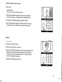
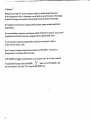
INITIAL SET UP
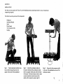
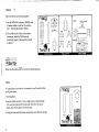
Now that you have unpacked the Taurus II, save the shipping cartons and packing materials in case any long distance
transporting is required.
First check to see that you have all the components:
Pedal board
Synthesizer Module
Stand
Power Supply
5 Pin Connector Cable
Gig Bag
Step 1:
Take the stand and carefully screw
Step 2:
Attach the synthesizer module to
Step 3:
Connect the 5-pin connector cable
the end with the larger thread into the
the stand. Underneath the synthesizer module
to the rear of the pedalboard and rear of the
adapter in the center of the pedal board.
there is an adapter which mates with the thread
synthesizer module.
of the stand. The thread is long in order to make
a sturdy connection so several turns of the
module will be required to make a tight fit.
Step 4:
Plugihe 24 volt power supply cord into the POWER IN jack on the rear of the synthesizer module,
plug the other end in the power outlet, then turn on the power switch on the front panel.
AMPLIFIER
Step 5: Using a 1/4" jack audio cord, connect the AUDIO OUT on the rear of the Taurus II to your amplifier
or monitoring system.
Always allow at least 10 minutes for any synthesizer to warm up prior to tuning up.
If no sound is heard, first check that all connections have been made properly.
Check the 5-pin connectors at each end.
Check that the power supply is pushed in all the way in the power outlet.
Check the power-in jack plug, at the rear of the synthesizer module, to see if it is inserted correctly. The power light
above the power-on switch should be glowing.
Check the audio cord by substituting it for another. Alternatively, turn the amplifier volume to a low level,
disconnect the audio cord from the Taurus II and touch the end of the jack plug. If a hum is heard, the cord is O.K.
If you have any problems with the Taurus II, you should first contact the dealer you purchased it from. Any technical
problems usually can be solved by the dealer. Service centers and our own Service Department are also on hand
to assist you. Information on the service center nearest you can be obtained by contacting:
Moog Service Department
2500 Walden Avenue, Buffalo, NY 14225; (716) 681-7242
•: .■*'•
SECTION 4
AMPLIFICATION
To get the best sound reproduction for Taurus II
Taurus II is a powerful monophonic synthesizer. Many of you will use it primarily for bass sounds, however it will produce
a wide range of pitch and tone color just like any other synthesizer. If you are going to use Taurus II for bass synth work only,
a bass amplification system will suffice. However, if you intend to continually use a variety of contrasting sounds, try to use
an amplification system which is designed for synths/keyboards. Your Moog dealer will be able to advise you on this subject.
TRYING OUT SOME SOUNDS
OECAY
ATTACK
SUSTAIN
10—
OSC 1
CD
7 \
.3
30
OCTAVE
SHAPE
32'
OSC
CD
a ru -v
OUT
SYNC
OSC 2 TO OSC 1
RATE (HZ)
CD
0FF
ott
16'
16'
lU
-CD
6'
7 -
IN
AUTO TRIG
^^-^ MOD
a
CONTOUR
CONTOUR
iu
' BYPASS
KEYED
GENERATOR
CUTOFF
EMPHASIS
AMT
TaurUs/T n
CONTHOLLEnS
7\
0
CD
OFF
ON
OSC 2
VCF
CD
OFF
ON
10
INTERVAL
GLIDE
MODULATION
KEYBOARD
TRACK
OSCILLATORS
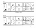
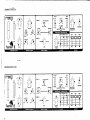
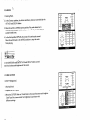
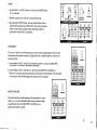
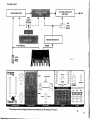
Taurus II sound charts are line drawings of the instrument's front panel. Positions for placing toggle switches,
rotary controls and sliders are indicated by dots.
To help you remember your own front panel settings (patches) we have included two blank sound charts on page 18.
We suggest you photocopy them to have a supply of blanks. If you create a sound you wish to use again
(especially when you're experimenting or recording) write it down. You'd be surprised how easy it is to
forget that hot patch.
0
POWER
MASTER
VOLUME
—10
PITCH
ON
10
A
CD-
32'
M/
VCA MODE
WAVEFORM
8'
1O-
CD
OFF ON CONTOURED
OSC 1
OSC 2
NOISE
r\
o
r\
a!)
ci Tip
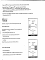
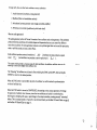
•These sound charts are designed to guide you toward a particular sound. After setting up the patch,
experiment by moving one or two controls. By making several adjustments, you might find a sound you prefer.
Suggested controls to experiment with are:
1. Cutsdff slider in the Filter section. (This controls the brightness of the sound.)
2. Octave switch in the Oscillator section. (This switch selects the overall pitch of the instrument.)
3. Attack and Decay sliders in the Contour Generator. (These control the rise and fall of the loudness
and the filter.)
O.K. You're eager to start playing the Taurus II. Set up these patches and get an idea of the many sounds
Taurus II can produce.
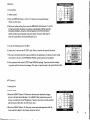
ORIGINAL TAURUS VOICE
ATTACK
nnoog-
DECAY
SUSTAIN
OSC 1
OUT
.3
SYNC
30
SHAPE
OCTAVE
OSC
32*
16*
a
81
OFF
0N
32*
16'
CONTOUR
ru
8'
POWER
O -
WAVEFORM
ILJ
MASTER
' BYPASS
VOLUME
KEYED
CONTOUR
a ru -v
IN
VCA MODE
OSC 2 TO OSC 1
RATE (H2>
ON
OFF ON CONTOURED
V V
TUNE
10-
GENERATOR
CUTOFF
EMPHASIS
AMT
— 10
AUTO TRIG
PITCH
a-«v
TaurusTJ n
0
OFF
NOISE
10
*
UNISON
ON
OSC 2
O5C 2
VCF
MOO
OFF
OSC 1
10
OCTAVE
7\>
ON
10
INTERVAL
GLIDE
. CONTROLLERS -■
OSCILLATORS}
.MODULATION
Note: Detune Osc 2 slightly
i Ttp
Detuning helps to get a richer, fatter sound. Only a small amount is enough to get the desired effect.
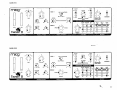
BASS 1
ATTACK
ON
OSC 1
OFF ON
CONTOURED
OUT
7 V
SYNC
.3
OSC 2 TO OSC 1
30
OCTAVE
RATE (HZ>
TUNE
SHAPE
32*
OSC
WAVEFORM
a
16'
ru
0 ~\
CONTOUR^
KEYED
CONTOUR
0N
A fU "V
32'
16'
IN
VCA MODE
fU
8'
-
' BYPASS
VOLUME
CUTOFF
EMPHASIS
AMT
PITCH
^^'"K
OSC S
VCF
MOD
UNISON
OFF
Taurdsfl n
CONTROLLERS
0
ON
OFF
10
INTERVAL
GLIDE
— s
OCTAVE
ON
7\
KEYBOARD
TRACK
MODULATION
OSCILLATORS
Note: Detune Osc 2 slightly
POWER
10
GENERATOR
-—10
AUTO TRIG
0
MASTER
—0
OSC 1
OSC 2
NOISE
10
BASS II
-*,
DECAY
maog
SUSTAIN
OSC 1
OUT
V\
TUNE
SYNC
OSC 2 TO OSC 1
RATE (HZ)
OSC
32*
16*
off
AUTO TRIG
PITCH
32'
B'
16'
A
CONTOUR
OJ
^^*\ MOD
Tauruin H
8*
IU
KEYED
UNISON
OFF
0
ON
OFF
OCTAVE*
' BYPASS
GENERATOR
CUTOFF
EMPHASIS
AMT
10
OSC 1
OSC 2
NOISE
A
A
r>
7 V
ON
10
GLIDE
POWER
io
MASTER
VOLUME
M/.
oscs
VCF
V V
o
WAVEFORM
CONTOUR
a ru -v
IN
VCA MODE
OCTAVE
SHAPE
ON
OFF ON CONTOURED
INTERVAL
KEYBOARD
TRACK
CONTROLLERS
MODULATION
OSCILLATORS
Note: Detune Osc 2 slightly
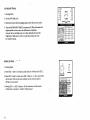
BASS III
DECAY
SUSTAIN
M/.
OSC 1
OFF ON
OUT
'4 V
.3
SYNC
0
OCTAVE
SHAPE
OSC
32*
16'
WAVEFORM
8'
A
CONTOUR^
IU
KEYED
CONTOUR
A HI -V
OFF
AUTO TRIG
0N
32*
16'
81
(U
VCF
UNISON
OFF
Taurus/J n
CONTROLLERS
0
ON
OFF
\\/.
10
GLIDE
INTERVAL
MODULATION
7 V
KEYBOARD
TRACK
oscillator:
Note: Watch the Master Volume on this patch
8
.
BYPASS
POWER
10
VOLUME
GENERATOR
CUTOFF
OCTAVE
/\
MASTER
EMPHASIS
AMT
OSC 1
10,
ON
ON
IN
VCA MODE
OSC 2 TO OSC 1
30
RATE (HZ)
TUNE
\tv
CONTOURED
OSC 2
NOISE
00
CN
0)
o
4-1
Z
^
<
o
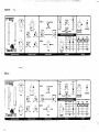
BASSV
ATTACK
ITtEJOg
SUSTAIN
OSC
OUT
SYNC
OSC 2 TO OSC 1
SHAPE
32'
OSC
16*
32'
OFF
8*
16'
A
CONTOURV
OJ
VOLUME
KEYED
8'
PITCH
GENERATOR
CUTOFF
EMPHASIS
AMT
VCF
UNISON
ON
OFF
10
OSC 1
OSC 2
NOISE
M
A
r>
10
osc a
MOO
OFF
POWER
10
MASTER
' BYPASS
—10
AUTO TRIG
\
0
0 -
WAVEFORM
CONTOUR
A (U -V
IN
VCA MODE
OCTAVE
RATE (HZ)
TUNE
ON
OFF ON CONTOURED
— 5
OCTAVE
ON
—0
INTERVAL
CONTRO LLERS
OSCILLATORS
MODULATION
BASS VI
DECAY
ATTACK
10-
SUSTAIN
OSC 1
OUT
7.V
.3
SYNC
OSC 2 TO OSC 1
30.
RATE (HZ)
TUNE
SHAPE
321
16'
0 -
A
B'
IU
CONTOUR
KEYED
CONTOUR
A OJ-V
0FF
AUTO TRIG
0M
16'
B1
nj
UNISON
4O
CONTROLLERS
0
OFF
ON
OFF
OCTAVE
ON
10
INTERVAL
GLIDE
MODULATION
KEYBOARD
TRACK
BYPASS
EMPHASIS
POWER
MASTER
VOLUME
GENERATOR
CUTOFF
VCF
PITCH • ^^"N M0D
TaurusHlI
32*
IN
VCA MODE
WAVEFORM
OCTAVE
OSC
ON
OFF ON CONTOUREO
AMT
BASS VII
ATTACK
10 —
OSC 1
OFF ON
ON
CONTOURED
OUT
7\
SYNC
.3
OSC 2 TO OSC 1
30
SHAPE
0
OCTAVE
RATE (HZ)
32*
OSC
16'
IN
VCA MODE
WAVEFORM
A
8'
CONTOUR
RJ
KEYED
POWER
10
MASTER
BYPASS
VOLUME
CONTOUR'. GENERATOR.
a ru -v
0FF
0M
32'^ 16'
B'
IU
CUTOFF
EMPHASIS
AMT
—10
OSC S
AUTO TRIG
UNISON I
OFF
0
ON
OFF
ON
0
10
INTERVAL
GLIDE
'
1
_
KEYBOARD
TRACK
modulation;
i CONTROLLERS:
. OSCILLATORS'
BASS VIII
mexog
SUSTAIN
OSC 1
OFF ON
OUT
SYNC
.3
SHAPE
32P
OSC
16'
8'
A
RJ
CONTOUR^
KEYED
CONTOUR
a ru -v
0FF
0N
32'
16'
'IN
0
WAVEFORM
OCTAVE
ON
VCA MODE
OSC 2 TO OSC 1
30
RATE (HZ)
10-
CONTOURED
OJ
8'
/\
POWER
10
MASTER
BYPASS
VOLUME
GENERATOR
CUTOFF
EMPHASIS
AMT
OSC 1
OSC 2
NOISE
^
^
r\
OSC 2
OCTAVE
OFF
ON
OFF
ON
KEYBOARD
TRACK
MODULATION
11
BASS IX
-•&
DECAY
ATTACK
ITTEOg
10-
OSC 1
.3W
OFF ON CONTOURED
SYNC
OSC 2 TO OSC 1
30
RATE (HZ)
TUNE
SHAPE
WAVEFORM
OCTAVE
OSC
32'
SUSTAIN
16*
A
6'
7 V
0 -
CONTOUR
flJ
32*
AUTO TRIG
PITCH
16*
A
osc e
VCF
MOD
Taurusf/ n
6'
UNISON
V
OFF
ON
OFF
OJ
VOLUME
KEYED
CONTOUR
A fUV
POWER
MASTER
GENERATOR
CUTOFF
EMPHASIS
AMT
—10
M/
OSC 1
101
OSC 2
OVEP
NOISE
DRIVE
5 —
OCTAVE-
ON
§—"
INTERVAL
OSCILLATORS
MODULATION
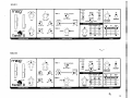
SOLO I
frraog
ATTACK
l/\t7N
DECAY
SUSTAIN
0FF On
.3
SYNC
OSC 2 TO OSC 1
30
OCTAVE
RATE (HZ)
TUNE
SHAPE
32*
OSC
16'
At/
CONTOURED
OUT
7\
10~
IN
VCA MODE
o
a
POWER
10
MASTER
WAVEFORM
8'
ON
VOLUME
ru
CONTOUR 'GENERATOR
a ru -v-
off
on
32'
16'
A
81
IU
CUTOFF
EMPHASIS
AMT
— 10
AUTO TRIG
PITCH
MOO
Tauri/sfJ H
UNISON
/\
0
OFF
ON
OFF
.
OCTAVE
ON
10
INTERVAL
GLIDE
MODULATION
12
OSC 2
VCF
7V:
KEYBOARD
TRACK
OSC 1
OSC 2
NOISE
A
A
n
OVER
DRIVE
■ 10
SOLO II
ATTACK
meog
OECAV
10 —
OSC 1
V V
SYNC
OSC 2 TO OSC 1
30
SHAPE
32'
OSC
16'
OFF
IN
0
WAVEFORM
6'
a
CONTOUR
ru
A
0N
RJ
POWER
10
MASTER
BYPASS
KEYED
CONTOUR
a ru -v
ON
VCA MODE
OCTAVE
RATE (HZ)
Ma
ci§)
OFF ON CONTOURED
OUT
.3
10-
SUSTAIN
VOLUME
GENERATOR
CUTOFF
EMPHASIS
OSC 1
AMT
OSC 2
NOISE
—10
OSC S
AUTO TRIG
PITCH
^fc. -«w
MOD
UNISON
OFF
TaurtfsH n
0
ON
OFF
OCTAVE
ON
10
INTERVAL
GLIDE
KEYBOARD
TRACK
CONTROLLERS ■
- OSCILLATORS-
. MODULATION
SOLO III
DECAY
ATTACK
maog
10—(
OSC 1
10-
OUT
7 V
-7 V-
,3
SYNC
OSC 2 TO OSC 1
30
RATE (HZ) '
SHAPE
OCTAVE
32"
OSC
16'
0FF
0N
32-
16'
8'
-7 V
o
WAVEFORM
8"
IN
VCA MODE
A
RJ
CONTOUR
KEYED
CONTOUR
a ru -v
ON
OFF ON CONTOURED
A
OJ
BYPASS
VOLUME
GENERATOR
CUTOFF
EMPHASIS
AMT
OSC 1
^ -«s
MOD
OCTAVE
OFF
Taurtfs
0
ON
OFF
OSC 2
OVER
osc a
PITCH
POWER
10
MASTER
NOISE
ORtVE
— 6
5-
ON
10
GLIDE
MODULATION
■-<&■■
13
SOLO IV
DECAY
ATTACK
10-
10 —
OSC 1
OUT
7 \
.3
SYNC
OSC 2 TO OSC 1
30
TUNE
SHAPE
OSC
32'
16'
A
8'
CONTOUR
fll
KEYED
CONTOUR
A IU-V
°rF
ON
32*
A
16'
IN
V \
VCA MODE
WAVEFORM
OCTAVE
RATE (HZ)
AI/.
OFF ON CONTOURED
IU
o
' BYPASS
VOLUME
GENERATOR
CUTOFF
EMPHASIS
AMT
OSC 1
OSC 2
NOISE
n
r\
n
—10
^.-«\
10
osc a
AUTO TRIG
PITCH
POWER
io
MASTER
MOD
OFF '
ON
OFF
ON
Tauru's
KEYBOARD
TRACK
INTERVAL
OSCILLATORS
MODULATION
CONTROLLERS'
SOLOV
DECAY
ATTACK
msxrj
10 —
10 —
OSC 1
OUT
7.V
.3
SYNC
OSC 2 TO OSC 1
30
TUNE
SHAPE
32'
OSC
16'
-7 \*
o
0 -
A
8'
IN
VCA MODE
WAVEFORM
OCTAVE
RATE (HZ)
AlA
OFF ON CONTOURED
111
CONTOUR^
POWER
io
MASTER
' BYPASS
VOLUME
KEYED
CONTOUR GENERATOR
a ru -v
0FF
0M
32*
16'
A
8"
IU
CUTOFF
EMPHASIS
AMT
—10
osc a
AUTO TRIG
PITCH
A--v
— 5
MOD
OFF
ON
OFF
ON
i Taurus" II
CONTROLLERS
KEYBOARD
TRACK
MODULATION
OSCILLATORS
* Tune to a perfect fifth
14
OSC 1
OSC 2
NOISE
n
r\
rs
■
OVER
DRIVE
■
SOLO VI
DECAY
ATTACK
10—
OSC 1
OFF ON
[3]
/\
SYNC
OSC 2 TO OSC 1
30
32*
SHAPE
>6*
IN
VCA MODE
0
OCTAVE
RATE (HZ)
ON
CONTOURED
OUT
.3
10-
SUSTAIN
WAVEFORM
8*
A
CONTOUR
fU
KEYEO
.
POWER
10
MASTER
BYPASS
VOLUME
CONTOUR' GENERATOR
A flJ-V
0FF
ON
32*" 16*
8'
IU
CUTOFF
EMPHASIS
n
1Oi
AUTO TRIG
PITCH
VCF
UNISON
OFF
ON
OFF
NOISE
-
o_
drive
5 —
OCTAVE
ON
0
TaurusH II
oven
OSC 2
^^"\ M0D
OSC 2
OSC
AMT
0—
KEYBOARD
INTERVAL
GLIDE
TRACK
oscillators:
MODULATION
CONTROLLERS::
SOUND EFFECTS I
DECAY
ATTACK
meog
SUSTAIN
OSC 1
OUT
7\
SHAPE
32'
OSC
16'
0 WAVEFORM
A
8'
[U
CONTOUR^
KEYED
CONTOUR
A IUV
PITCH
^^-^
MOD
Tauruln n
CONTROLLERS
AIA
otl
32'
16'
8'
IU
' BYPASS
0
VOLUME
GENERATOR
CUTOFF
AUTO TRIG
osc a
VCF
UNISON
ON
OFF
10
EMPHASIS
AMT
OSC 1
OSC 2
NOISE
m
fr
r>
I
DVER
DRIVE
■
10
5 —
OCTAVE
ON
0 —
INTERVAL
GLIDE
POWER
10
MASTER
10
OFF
"
0FF
IN
VCA MOOE
OCTAVE
HATE <HZ»
ON
OFF ON CONTOURED
SYNC
OSC 2 TO OSC 1
TUNE
10 —
-0
KEYBOARD
TRACK
MODULATION
OSCILLATORS
15
SOUND EFFECTS II
DECAY
ATTACK
rrwog
SUSTAIN
10 —
r—i
OSC 1
\
OUT
SHAPE
32'
OSC
16*
IU -V
OFF
AUTO TRIG
PITCH
A«v
ON
32'
A
8*
16'
Taurus/7 n
A
8'
UNISON
ON
OFF
CONTOUR
RJ
IU
BYPASS
KEYED
POWER
to
MASTER
VOLUME
GENERATOR
CUTOFF
EMPHASIS
AMT
OCTAVE
ON
KEYBOARD
INTERVAL
GLIDE
TRACK
OSCILLATORS
MODULATION
CDNTROLLERB
o
0 -
osc a
VCF
MOD
OFF
V V
VCA MODE
WAVEFORM
CONTOUR
A
IN
0 -
OCTAVE
RATE (HZ)
ON
OFF ON CONTOURED
SYNC
OSC 2 TO OSC 1
TUNE
10
SOUND EFFECTS III
DECAY
ATTACK
meog
10 —
\\A
OSC 1
OFF ON
OUT
.3
SHAPE
32'
OSC
16'
0
WAVEFORM
OCTAVE
A
8'
RJ
CONTOUR>
KEYED
CONTOUR
a ru -v
0FF
ON
32'
16'
8'
IN
VCA MODE
OSC 2 TO OSC 1
30
RATE (HZ)
ON
CONTOURED
SYNC
TUNE
10-
SUSTAIN
A
IU
o
-
VOLUME
GENERATOR
CUTOFF
EMPHASIS
OSC 1
AMT
-10
AUTO TRIG
PITCH
A**t
QSC B
VCF
MOD
UNISON
OFF
Taurus/7 H
^CONTROLLERS
ON
OFF
-s
OCTAVE
ON
—0
INTERVAL
GLIDE
KEYBOARD
TRACK
MODULATION'
POWER
10
MASTER
BYPASS
IOi
OSC 2
NOISE
■ 10
SOUND EFFECTS IV
OECAY
ATTACK
maog
10 —
AI
7 \
.3
OSC 1
(5
OFF ON CONTOURED
OUT
SYNC
OSC 2 TO OSC 1
30
SHAPE
32"
OSC
16'
AIA
)
IN
VCA MODE
WAVEFORM
OCTAVE
RATE (HZ)
TUNE
10 —
SUSTAIN
A
8"
CONTOUR
fU
KEYED
o
POWER
io
MASTER
' BYPASS
VOLUME
CONTOUR GENERATOR
a ru -v
0FF
0N
16"
IU
8'
CUTOFF
EMPHASIS
AMT
OSC 1
OSC 2
NOISE
OSC S
AUTO TRIG
■>v
32'
MOO
OFF
Taurus// II
0
ON
OFF
ON
10
KEYBOARD
GLIDE
TRACK
O8CI1XATQRB'
CONTROU-ERB
SOUND EFFECTS V
DECAY
ATTACK
rrwog
10 —
OSC 1
OFF ON
SYNC
.3
SHAPE
WAVEFORM
OCTAVE
32'
OSC
16'
IN
VCA MODE
OSC 2 TO OSC 1
30
RATE (HZ)
TUNE
ON
CONTOURED
OUT
7 V
10-
SUSTAIN
A
8"
fll
CONTOUR>
KEYED
POWER
MASTER
' BYPASS
VOLUME
CONTOUR GENERATOR
a ru -v
0FF
0N
32"
16'
IU
81
CUTOFF
EMPHASIS
AMT
OSC 1
OSC 2
NOISE
r\
n
n
...
osc 2
AUTO TRIG
PITCH
OCTAVE
^^"^ MOO
TaurSW II
CONTROLLERS
V v
0
OFF
ON
OFF
ON
10
GLIDE
MODULATION
OSCILLATORS
* Switch ON Auto Trig to introduce
repetitive effect
Use pedals to vary pitch
17
Permission is given to copy for non-commercial purposes.
ON
CD
.3
TUNE
30
32'
OSC
CD
CD
fU -V
OFF
ON
16'
A
8'
16»
A
CONTOUR
VOLUME
GENERATOR
CUTOFF
ILJ
EMPHASIS
1
AMT
—10
PITCH
MOO
Tauru'sJT II
/ v
Vm"
VCF
CD
CD
ON
OFF
UNISON
NOISE
110
— 5
OCTAVE
ON
—0
KEYBOARD
INTERVAL
TRACK
OSCILLATORS
MODULATION
CONTROLLERS
OSC 2
10 ■
osc a
AUTO TRIG
OFF '
0
POWER
10
MASTER
ASS
RJ
■CD
8'
0
0 -
O -
WAVEFORM
CD-
32'
IN
VCA MODE
OCTAVE
SHAPE
A
OUT
SVNC
OSC 2 TO OSC 1
RATE (HZ)
$ $
CD
OFF ON CONTOURED
SUSTAIN
CD
/\
.2
TUNE
PITCH
MOD
30
OSC
CD
CD
0FF
0N
AUTO TRIG
VCF
CD
CD
OFF
ON
OFF
TaurifsfJ II
CONTROLLERS
16*
16'
A
MASTER
CONTOUR -.GENERATOR
CUTOFF
III
EMPHASIS
—5
OCTAVE
ON
—0
.KEYBOARD
TRACK
OSC
AMT
—10
UNISON
0
POWER
VOLUME
flJ
■CD
8'
INTERVAL
^.MODULATION
0 -
A
8"
CD-
32'
0 -
WAVEFORM
OCTAVE
32'
IN
VCA MODE
OSC 2 TO OSC 1
SHAPE
a ru -v
OUT
SYNC
RATE (HZ)
S£
CD
OFF ON CONTOURED
10
OSC 2
NOISE
10
SECTION 5
GETTING TO KNOW TAURUS II
One of the best ways to become familiar with an instrument is to experiment with it. So rather than explain in detail
how each control works, let's just look at each function of the front panel and listen to the influence
it has on the sound.
A STARTING PATCH
DECAY
ATTACK
moog*
10 —
10 —
OSC 1
OUT
.3
SYNC
OSC 2 TO OSC 1
30
RATE (HZ)
TUNE
SHAPE
321
16'
0FF
0N
32'
16'
-7 V
o
WAVEFORM
B'
A
III
CONTOUR
KEYED
CONTOUR
A RJ -V
IN
VCA MODE
OCTAVE
OSC
ON
OFF ON CONTOURED
8'
OJ
BYPASS
VOLUME
GENERATOR
CUTOFF
EMPHASIS
AMT
—10
AUTO TRIG
PITCH
Taurite77 n
UNISON
It
ON
OFF
OSC 2
NOISE
10
— 5
OCTAVE
ON
INTERVAL
GLIDE
controllers.
OSC
101
osc a
VCF
MOO
OFF
POWER
io
MASTER
7K j
—0
KEYBOARD
TRACK
MODULATION
OSCILLATORS
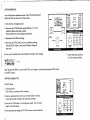
Here is a patch to provide a convenient starting point.
The control panel is laid out in six separate sections:
1. Controllers
4. Contour Generator
2. Modulation
5. Filter
3. Oscillators
6. Mixer and Final Output
ftp
Remember, if you get stuck, return to the Starting Patch and try again.
19
TUNING
-?4
Once you have set up the starting patch:
OSC 1
1. Set the INTERVAL control at UNISON and,
•
OFF ON CONTOURED
CD
if needed, adjust it until Osc 2 is tuned to
SYNC
OSC 2 TO OSC 1
Osc 1. (No beating should be heard.)
2. If you wish to tune Taurus II to another
instrument, adjust the TUNE control
accordingly (again no beating effect should
be heard).
CD
CD
0PF
CD
ON
0N
16'
UNISON
T
1. Starting Patch.
2. Set the GLIDE control to 5, play a high note and while holding
TUNE
this note down depress the lowest pedal. Note how the pitch
glides down to the pitch of the lowest note.
3. Using the same pedal techniques, experiment with different settings.
PITCH
Taur
CONTROLLERS
20
OCTAVE'
OSCILLATORS
GLIDE
on the pedal board.
A
ON
Check that the pitch wheel is in its center notched position.
fU
■CD
8*
MODULATION
it's a good idea to sit down for this exercise as you'll need both feet
A
6'
CD —
32'
CD
OFF
16-
osc a|.^fV
VCF
AUTO TRIG
OFF
32
OSC
a ru -v
WAVEFORM
OCTAVE
RATE 1H2|
SHAPE
IU
PITCH WHEEL
Expression is a very important aspect of producing music on a musical instrument.
nraog*
With the synthesizer, expression can be introduced by using the Pitch and
Modulation wheels.
Experiment - get to know the feel of the wheel, how far it should be moved.
TUNE
1. Starting Patch.
2. The wheel has a neutral center notched position. Check to feel the wheel is in
its center position.
3. Moving the Pitch Wheel upwards bends the pitch up; moving the wheel
7. V
Taur
downward bends the pitch down.
GLIDE
carvrraoLLERB
4. Return the wheel to its center position.
Moving the Pitch Wheel just small amounts can bend the pitch in subtle expressive ways. Small pitch glides
can also be achieved using the Pitch Wheel. Even rocking the Pitch Wheel around its notched central
position can produce interesting modulation of pitch. Large continuous movements of the Pitch Wheel
will create sound effects.
You can even transpose melody lines by leaving the wheel set at a desired interval.
MODULATION WHEEL
The Modulation Wheel works in conjunction with the various controls
in the Modulation section.
rraxj*
1. Starting Patch.
^' O'
t
2. Moving the Mod Wheel upwards introduces modulation. Play a note
n
and listen to the following effects:
7\
TUNE
3. Adjusting the RATE (Hz) control (at the top of the Modulation
section) will speed up or slow down the modulation rate.
P.TCH
4. Leave the Mod Wheel in a central position, and switch OFF the
OSC switch. You now have only filter (VCF) modulation or tremolo.
Taur
GLIDE
CONTROLLERS
MODULATION
21
5. Now switch OFF the VCF switch and turn ON the OSC switch. This is pitch modulation (vibrato).
6. Switch SHAPE from ( A )Triangle to ( JT ) Square Wave. Listen to the difference.
Now move the 3-position switch to ( yH. ) Random Waveshape. This is a popular sound effect
"sample and hold." While leaving this effect on, switch the AUTO TRIG switch to ON. The sample and
hold effect will now play continuously.
7. Experiment trying out different combinations of switches, varying degrees of Mod amount from the Mod Wheel
and varying amounts of RATE.
OSC 1
OFF ON CONTOURED
CD
SVNC
Remember, if you get stuck, return to the Starting Patch and try again.
OSC 2 TO OSC 1
.
OCTAVE ^
32*
161
WAVEFORM
a
8'-
OSCILLATOR OCTAVES
s 321
The oscillators are the heart of a synthesizer. This is where pitched sound
is generated.
I61
A
8*>
osc a
^-—v.
UNISON
OCTAVE
1. Set up the Starting Patch. OCTAVE is at 16\
INTERVAL
2. Move the switch left to 32\ Notice the pitch of the Taurus II
OSCILLATORS
is now an octave lower.
3. Moving the OCTAVE switch to the right to 81 will raise the pitch
two octaves.
(The OCTAVE switch controls the pitch of both oscillators.)
OSC
OFF ON CONTOURED
CD
SYNC
OSC 2 TO OSC 1
OCTAVE
OSCILLATOR WAVEFORM
32'
>. Move the WAVEFORM switch to the right. Note the different tone color.
j. The WAVEFORM switch controls the waveform for both oscillators.
8'
CD-
32'
I. Set up the Starting Patch.
16'
16'
ru
■CD
8'
OSC E
OCTAVE
UNISON
INTERVAL
IU
OSCILLATOR 2 INTERVAL
1. Set up the Starting Patch.
2. Turn the INTERVAL control from UNISON to OCTAVE. (This moves the pitch of
OSC 1
OFF ON CONTOURED
CD
OSC 2 one octave above OSC 1.) Gently moving the control, listen until the
SYNC
beating effect disappears. Fine tuning will ensure a perfect octave interval.
OSC 2 TO OSC 1
OCTAVE
3. Now experiment with finding intervals between UNISON and OCTAVE. Setting the
oscillators at intervals enriches the tone quality. Settings of a perfect fifth or fourth
32*
16'
8'
CD
32*
16'
a*
are frequently used because of the organ-like tone colors created.
Moving the Interval control left of UNISON will give OSC 2 intervals below
the pitch of OSC 1.
OSCILLATORS
//
i up
Remember to return the Interval control to UNISON when completing this exercise. Notice once more
that the "beating effect" will disappear when the two oscillators are exactly in tune.
However, slow beating (slight detuning) does produce a fatter sound.
OSC SYNC (OSC 2 TO OSC 1)
1. Set up the Starting Patch.
OSC
The OSC SYNC switch has three positions. In the OFF position, the Oscillators are not
synchronized and may be detuned as above.
WAVEFORM
OCTAVE
2. Move the switch to ON (the second position).
32'
3. No difference will be heard until you turn the INTERVAL control. Notice the
32 ■
changing tone color while moving this control. Experiment with different settings.
4. Return the INTERVAL control to the UNISON position. (An exact position
is not required at this stage.)
5. Now move the SYNC switch right to CONTOURED. (Refer to Contoured Sync
16'
A
a*
CD16'
fU
IU
8'
oscs
OCTAVE
UNISON
INTERVAL
OSCILLATOR!
section on the following page.)
23
CONTOURED^YNC
Look at the Contour Generator section. The ATTACK and DECAY
sliders will affect the tone color in this exercise.
repeatedly depress and release a pedal.
Notice that trie tone color'changes automatically.
3. Experiment with different settings.
;to-
SUSTAIN
•
.1. First, listen to the original sound.
2. Now move the ATTACK slider upward halfway to "5" and
I-"* DECAY
" ATTACK
16'
WAVEFORM
CD
32'
16'
a
8'
OUT
i
OSC2 TO
OCTAVE
32'
CD
OfF O« CONTOUREO
■*- CONTOUR
ru
CD
A
8"
IN
VCA MODE
KEYED
CONTOUR
flJ
GENERATOR
CUTOFF
EMPHASIS
AMT
#
1-10
OBC S
UNISON
— 5
OCTAVE
4. Now leave the ATTACK at 0 and try out different settings
with the DECAY slider. Listen for the different changes of
tone color.
—0
KEYBOARD
TRACK
INTERVAL
OSCILLATORS
By now you will realize these controls affect the timing of tone changes.
* Filter AMT slider should be
at 10 for maximum effect.
After using the INTERVAL control with SYNC, don't forget to retune after placing the SYNC switch
in the OFF position.
CONTOUR GENERATOR
DECAY
ATTACK (Rise)
OUT
1. a) Starting Patch.
CONTOUR>
CONTOUR
GENERATOR
CUTOFF
3. Move the ATTACK slider to 10 and depress a pedal. The note takes
longer to build its volume.
24
' BVPASS
KEYED
as soon as the pedal is released, the note stops sounding.
4. Now experiment by setting the ATTACK control in various positions.
IN
VCA MODE
b) Set Contour controls and filter as shown:
2. Depress a pedal and listen to the way the note builds in volume;
10 —
SUSTAIN
Ow
1
KEYBOARD
TRACK
EMPHASIS
AMT
CONTOUR GENERATOR (Continued)
DECAY (Fall)
ATTACK
l.a) Starting Patch.
b)Set Contour controls and filter as shown:
10 —
SUSTAIN
OUT
2. Depress and immediately release a pedal. Notice the sound takes
IN
VCA MODE
some time to fade away. This length of time is called decay time.
CONTOUR >
KEYEO
BYPASS
CONTOUR GENERATOR
3. Experiment with different settings of the DECAY slider. ~
4. Now combine different settings of ATTACK and DECAY until you
feel confident about the affect these controls have on the sound.
SUSTAIN
1. Starting Patch.
2. Switch off the SUSTAIN switch.
ATTACK
DECAY
10 —
3. Depress a pedal and listen to the sound.
IN
VCA MODE
4. Now switch in SUSTAIN and listen to how the note holds loudness and
brightness at its peak while the pedal is depressed and then falls off
at the Decay time when the pedal is released. Try maximum DECAY
time (10) to emphasize this example.
5. Experiment with different Decay levels.
CD' BYPASS 0A
0 -
CONTOUR^
KEYEO
CONTOUR GENERATOR
CUTOFF
M/. -
EMPHASIS
AMT
—10
—5
;/\N j
KEYBOARD
TRACK
25
VCA MODE
1. Starting Patch.
10 —
CD
OUT
ATTACK and DECAY sliders.
CONTOUR
FILTER SECTION
CUTOFF (Brightness)
1. Starting Patch.
2. Depress the low C pedal.
3. Move the CUTOFF slider to 10 and listen to the sound become much brighter.
Cutoff acts like a tone control for brightness. Experiment with
different settings.
AMT
— 6
—0
KEYBOARD
TRACK
both the loudness and brightness of the sound.
EMPHASIS
—10
Move the switch back to the KEYED position to stop the notes
In the CONTOUR modTth?ATTACK and DECAY sliders control
GENERATOR
CUTOFF
4. In the third position BYPASS, the notes will continuously sound.
-<Ht
* Otoi Tip
IN
O -
a pedal is held down.
from playing.
10 —
SUSTAIN
2. In the Contour position, the Attack and Decay times are controlled by the
3. Move the switch to KEYED center position. Play and release low C.
This note ends abruptly. In this mode, a note will only sound as long as
DECAY
ATTACK
EMPHASIS
.CONTOUR
GENERATOR
CUTOFF
EMPHASIS
AMT
1. Starting Patch.
2. Depress a pedal.
0
3. Move the EMPHASIS slider to 5, then 7.5. Notice how the sound becomes
1
_
KEYBOARD
TRACK
thinner and more nasal.
4. Watch your volume setting if you move the EMPHASIS slider between 7.5 and 10.
At this level the filter feeds-back to produce a high-pitched whistling (just like a
microphone feedback). Actually, what has happened is the filter has become
another sound source, producing a very pure sound. This source itself may be
useful for certain effects. See Sound Effects II and V.
5. Set up the following patch on the filter.
CONTOUR
GENERATOR
6. Depress low C and move the CUTOFF slider. Notice it controls the pitch of the sound.
7. Play top C and notice the pitch is also controlled by the pedal board. To obtain an exact tuning
from bottom C to top C, the KEYBOARD TRACK control may have to be adjusted.
8. Now experiment with various CUTOFF and EMPHASIS settings. These two controls interplay
to produce subtle to obvious tone changes. They play an important part in the overall sound quality.
AMT (Amount)
1. Starting Patch.
2. Depress a pedal.
CONTOUR
3. Move the AMOUNT slider to 0. Notice how the tone color drastically changes,
AMT
7 V* i
4. Move the AMOUNT slider to 10. Now play various notes and experiment with the
EMPHASIS
I3
just like it did with the Cutoff slider. The AMOUNT slider adjusts the amount of
Contour controlling the Cutoff (brightness). Therefore, the Attack and Decay sliders
and the Sustain switch affect the filter (tone color).
GENERATOR
CUTOFF
_
KEYBOARD
TRACK
Attack and Decay sliders in the Contour Generator section.
27
KEYBOARD
DECAY
ATTACK
10 —
SUSTAIN '
CD
1. Starting Patch.
OUT
2. Set the AMT slider to 0.
3. Depress the lowest then the highest pedal. Note the even tone color.
highest pedals and now notice the difference in brightness
between the low and high notes. It is often desirable to boost the
brightness of high notes in order to make them stand out more
for melodic reasons.
/ '
1. Starting Patch.
2. Move OSC 1 slider to 0. Depress a pedal and you will hear only OSC 2.
3. Move OSC 2 slider to 0 and return OSC 1 slider to 7.5. Now only OSC 1
will be heard. The level of each oscillator can be mixed to achieve
the balance you require.
4. Moving OSC 1 or OSC 2 sliders to 10 will introduce a small amount
of distortion to produce a "beefier" (fatter) sound.
28
IN
VCA MODE
0-
CONTOUR
KEYED
CONTOUR
4. Turn the KEYBOARD TRACK to maximum 10. Play the lowest and
MIXER SECTION
10~
BYPASS
"-
GENERATOR
NOISE
ATTACK
DECAY
SUSTAIN
ON
(~qj)
1. Set both OSC 1 and OSC 2 sliders to 0 and raise the NOISE slider
OUT
to 5 as indicated:
IN
VCA MODE
POWER
2. Depress a pedal and you will hear a non-pitched sound.
MASTER
VOLUME
3. By moving the CUTOFF slider, wind or surf-like effects can be
CONTOUR
GENERATOR
CUTOFF
achieved {see example, Sound Effects III). Also, other percussive
EMPHASIS
AMT
OSC 1 .
■
sounds can be created using the Attack and Decay sliders in
conjunction with the filter. Experiment.
KEYBOARD
TRACK
OSC 2
OVER
NOISE
DRIVE
■
10
***
OVERDRIVE
ON
This circuit is similar to the Minimoog mixer section where setting Oscillator level controls
0
at maximum also produces overdrive, a slight distortion, a desirable addition to fatten the
sound even more.
POWER
1. Set the sliders for OSC 1 and OSC 2 in the Mixer section to 5 and set the MASTER
VOLUME to 10. Play low C and listen to the sound.
2. Set the sliders for OSC 1 and OSC 2 to 10 and set the MASTER VOLUME to 8.
Play low C and notice the sound has more power because of the distortion. This fat sound
is very popular with the Minimoog and is used on many recordings.
ON
o
MASTER VOLUME
POWER
MASTER
VOLUME
This control sets the overall loudness of the instrument. For best
results, try to use the individual Oscillator level controls as high
OSC1
OSC 2
NOISE
as possible and then set the MASTER VOLUME level, to
optimize the quality of sound.
29
SECTION 6
•<
A CLOSER LOOK AT TAURUS II
How are the functions of Taurus II organized?
The best way to think of any synthesizer's functions is to think of the whole thing as a modular instrument.
A module may best be defined as an individual part that has its own special purpose. To understand and use
a synthesizer correctly, you need only to understand each of its modules. The "connecting" of one module
to another is easily done with the switches and controls on Taurus II.
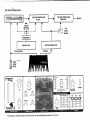
BASIC SYNTHESIZER FLOW CHART
VOLTAGE CONTROLLED
AUDIO GENERATORS
VOLTAGE CONTROLLED
AMPLIFIER
FILTER
MOD
SELECT
SWITCHES
|
£
VCA
r-
I
MOD WHEEL
MODULATION
PITCH CONTROL
PITCH
BEND
WHEEL
CONTOUR GENERATOR
I
MODE
SWITCH
>OUT
To begin with, there are four basic modules on every synthesizer:
1. Audio Generators (oscillators, noise generator)
2. Modifiers (filter and modulation sections)
3. Articulators (contour generator and voltage-controlled amplifier)
4. Performance Controllers (pedalboard, pitch bend wheel)
What are audio generators?
The audio generator portion of Taurus II consists of two oscillators and a noise generator. The oscillators
produce electrical waveforms with variable shapes and frequencies that you can control for different
tone colors or pitches. The noise generator produces a non-pitched signal that can be used for percussion,
wind or surf-like sounds and many other effects.
Both oscillators produce sawtooth waveforms (
wave (
|~LJ
/[/]/
). Oscillator one also produces a square
) and oscillator two produces a narrow pulse wave (
fl
I
)•
The octave switch provides a 3-octave range for both oscillators. In addition, oscillator two may be
tuned up to one octave higher than oscillator one.
The "detuning" of oscillator two is done by first switching the SYNC switch OFF, then turning the
INTERVAL knob to the desired position.
When the SYNC switch is turned ON, the pitch of oscillator two will be locked in synchronization
to that of oscillator one.
When the SYNC switch is turned to CONTOURED, the settings on the contour generator will change
the spectrum of oscillator two. However, since the two oscillators are locked in synchronization,
this frequency sweeping will cause a rapid change in the output waveform, creating unusual "screaming"
effects. This is a unique sound on Taurus II; it can be heard clearly on the Bass III Sound Chart on page 8,
and the Bass VII Sound Chart on page 11.
31
THE AUDIO GENERATORS
VOLTAGE CONTROLLED
VOLTAGE CONTROLLED
>OUT
AMPLIFIER
FILTER
MOD
SELECT
SWITCHES
VCA
I
J
MODE
SWITCH
MOD WHEEL
I
CONTOUR GENERATOR
MODULATION
PITCH CONTROL
PITCH
BEND
WHEEL
DECAY
\ I /
OUT
- -
7^
IN
VCA MODE
CONTOUR^
RATE (HZ)
SHAPE
CD
a ru -v
CD
0N
The shading on the above panel shows the location of the audio generator portion of Taurus II.
CUTOFF
EMPHASIS
VOLUME
AMT
OSC 1
n
U
POWER
MASTER
KEYED
OSC
0FF
^ BYPASS
0N
OSC 2
NOISE
■ 10
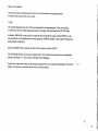
What are the modifiers?
There are two types of modifiers used on Taurus II, and since each has a very separate purpose,
it would be best to look at them one at a time.
1. Filter
This module changes the tone color of the sound produced by the audio generators. It does so by adding
or reducing the amounts of high frequencies present in the signal. This is controlled by the CUTOFF slider.
In addition, EMPHASIS may be added to increase the effect of the filter's function, and the CUTOFF can be
controlled further by the pedalboard and contour generator. EMPHASIS amplifies a narrow band of frequencies
surrounding the cutoff point.
Raise the AMOUNT slider to increase the effect of the contour on the filter CUTOFF.
The KEYBOARD TRACK control may be adjusted from "0" (no effect of the notes played on the pedalboard
is heard in the filter) to "1" (full control of the filter by the pedalboard).
A great many unusual tone colors may be produced using the filter, and a complete understanding of its function
will give you control over an almost infinite variety of musical sounds.
33
• V f -»
2. Modulators^
Modulation means change. The use of the modulators will give you unusual changes in the outputs
of the audio generators or filter. As the performer, you will be able to control the amount of these changes,
the speed of the changes, and the portions of the synthesizer that may be affected by these changes.
The modulation section of Taurus II provides such effects as vibrato, tremolo, automatic repetition and
sample-and-hoid
The actual modulation is produced by a low-frequency oscillator (LFO) built into Taurus II. You can control
its repetition rate with the RATE knob and its waveshape with the 3-position SHAPE switch.
You may then select to apply this modulation effect to either the two oscillators for vibrato or
the filter (VCF) for tremolo, or both, •
Note: The amount of modulation (amplitude) is controlled by the MOD WHEEL. If the wheel is in
its lowest position, no modulation effects will be heard.
AUTO TRIGGER will trigger the contour generator at each complete cycle of the LFO when turned ON.
For sample-and-hold patterns, select the RANDOM (
"r[/r ) shape, turn AUTO TRIGGER to ON,
route the modulation to OSC and/or VCF and raise the MOD WHEEL fully.
34
THE MODIFIERS
VOLTAGE CONTROLLED
AUDIO GENERATORS
AMPLIFIER
MOD
■►out
A
SELECT
T
SWITCHES
I
1
j
VCA
I
I
MODE
SWITCH
CONTOUR GENERATOR
PITCH CONTROL
PITCH
BEND
WHEEL
tz 0
POWER
The shading on the above diagram indicates the modulation and filter portions of Taurus II.
35
What are artictfjators?
The articulators are those portions of a synthesizer that allow the musician to control the loudness of the instrument,
the duration and shape of each tone, and the phrasing desired. On Taurus II, the contour generator controls
articulation. It is put into operation each time you depress a pedal on the pedal board or when triggered by the
AUTO TRIG function.
Sliders allow control of both the attack and decay times. These may be set from fast (0) to very slow (10). *
A SUSTAIN switch holds maximum loudness while a key is depressed.
The contour may be used to control the filter cutoff. This effect is created by raising the AMOUNT slider
in the Filter section.
A 3-position switch labeled VCA MODE applies the contour directly to Taurus ITs amplifier in position 1,
in center position allows the amplifier to be turned ON and OFF by the pedalboard alone, and leaves
the amplifier ON at all times in position 3.
♦Specific attack and decay times are listed in Taurus II Specifications in the back of this manual.
36
THE ARTICULATORS
VOLTAGE CONTROLLED
AUDIO GENERATORS
VOLTAGE CONTROLLED
FILTER
■►out
AMPLIFIER
MOD
SELECT
SWITCHES
VCA
r-
i
i
MODE
SWITCH
MOD WHEEL
1
^CONTOUR GENERATOR^
MODULATION
PITCH CONTROL
PITCH
BEND
WHEEL
meog
ATTACK
/
OSC 1
SHAPE
OSC
CD
CD
a ru -v
o^
AUTO TRIG
^^^ MOD
■ i :■:■
?£
0
POWER
RATE (HZ)
TUNE
PITCH
OECAY
CD
OFF
OH
on
OSC 1
OSC 2
NOISE
n
r\
r\
VCF
CD
OFF
Taurdsfl n
ON
INTERVAL
MODULATION
OSCILLATORS
The shading on the above diagram shows the location of the articulation portion of Taurus II.
37
What are the controllers?
The two primary controllers on Taurus II are the pedalboard and the pitch wheel. Each of these
will change the frequencies (and therefore the pitches) of the oscillators in the audio portion.
The pedalboard can also be used to alter the cutoff of the filter. This is controlled by the KEYBOARD
TRACKING knob on the filter section. The pedalboard is also directly connected to the articulation
portion of the instrument so that pitch and articulation are controlled simultaneously.
A GLIDE control allows theaddition of portamento (sliding from note to note) when playing on the pedals.
The speed of the glide is adjustable.
The TUNING knob controls both oscillators simultaneously.
The MIXER allows different levels of each oscillator and/or noise to be combined into the final output
(MASTER VOLUME control).
Note: When placed at the upper level (7.5 - 10) the mixer will automatically go into overdrive.
This is a distortion circuit built into the instrument. Overdrive creates a driving sound similar to,
but less dramatic than, that of a fuzz box or other guitar processors. It also helps to create a fatter sound.
For normal oscillator sound set MIXER at approximately 5.
38
THE CONTROLLERS
VOLTAGE CONTROLLED
AUDIO GENERATORS
VOLTAGE CONTROLLED
FILTER
AMPLIFIER
>OUT
MOD
SELECT
b
SWITCHES
I
.r
r-
1
VCA
J
j
1
MODE
■ SWITCH
MOD WHEEL
I
m
MODULATION
CONTOUR GENERATOR
PITCH CONTROL
TRIGGER
DECAY
ATTACK
10 —
OFF ON
OCTAVE
32'
SHAPE
OSC
CD
CD
OFF
0N
WAVEFORM
16'
8'
A
CD
32*
16'
IN
VCA MODE
OSC 2 TO OSC 1
30
a ru -v
UT
SYNC
RATE (HZ)
10 —
CD
CONTOURED
CD
/"v
.3
SUSTAIN
CONTOUR "
KEYED
CD
e1
a
.CD," BYPASS
0 -
RJ
CONTOUR
(LJ
GENERATOR
CUTOFF
EMPHASIS
AMT
—10
AUTO TRIG
CD
OFF
ON
VCF
CD
OFF
UNISON
OCTAVE
—5
ON
o
INTERVAL
IM
i
KEYBOARD
—0
TRACK
canrmDLLERB
MODULATION
OSCILLATDRS
The shading on the above diagram shows the locations of the controllers on Taurus II
39
SECTION 7 ■"*
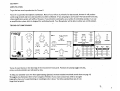
INTERFACING
Taurus II has a number of connectors on the rear panel which can be used to interface Taurus II with synthesizers,
sequencers and other instruments which are voltage controlled.
Interfacing can work in both directions. Taurus II can control or be controlled by another instrument. When interfacing
a Taurus II with another instrument, two connections are normally required: a control voltage (CV) and a trigger or gate.
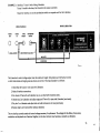
EXAMPLE 1:
Interface a Taurus II to a Source.
Taurus II would be the master, the Source the slave.
Reason for interface: bigger sound because of two synths playing plus programmability of The Source.
MOOG THE SOURCE
MOOG TAURUS II
AUDIO
OUT.
O
AUDIO
TRIG
KEYBOARD
IN
IN/OUT
IN/OUT
Or©
Or-9
UNBALANCED
FINE TUNE
•USE STEREO PLUG ONLYOUT ON TIP
OUT ON TIP
to
G-
AUDIO
KB-CV
S-TRIG
OUT
IN/OUT
IN/OUT
CASSETTE
'
IN ON RING.
IN ON RING
INTERFACE
EXAMPLE 2:
Interface a Taurus II with a Moog Liberation.
Taurus II would be the slave, the Liberation the master or controller.
Reason for interface: to use the synthesizer module as an expander unit for the Liberation.
MOOG LIBERATION
MOOG TAURUS II
AUDIO
AUDIO
TRIG
KEYBOARD
OUT
IN
IN/OUT
IN/OUT
o
-UNBALANCED
USE STEREO PLUG ONLY
The Liberation's control voltage output must be scaled and ranged. Scaling makes sure intervals are correct
on both instruments and ranging ensures unisons are correct. The proper procedure is as follows:
1. Check that the Taurus II is in tune with Liberation.
2. Make all interface connections.
3. Set volume of Taurus II and Liberation so you can hear both instruments clearly.
4. Depress top C on Liberation and adjust range until Taurus II is in tune with Liberation (zero beats).
5. Play low F on Liberation and adjust scale so both instruments are in tune (zero beats).
6. Repeat steps 4 and 5 until perfect tuning is obtained.
The two interface controls contain all control voltages necessary for performance. The voltages for the ribbon, force sensor,
modulation and keyboard are all summed together, so the slave instrument now becomes as versatile as Liberation.
41
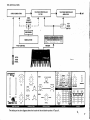
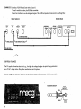
EXAMPLE 3:Mnterface a RS-09 Roland Synth with a Taurus II.
Taurus II would be the slave, the RS-09 the controller.
Reason for interface: to use the strings and organ of the RS-09 and produce a brass sound via the Moog filter.
ROLAND RS-09
MOOG TAURUS II
AUDIO
AUDIO
OUT
IN
TRIG
IN/OUT
KEYBOARD
IN/OUT
SUSTAIN
O
O
PEDAL
ORGAN
GATE RAWSIG
O
OUTPUT
PHONES
O
V-TRIG IN ON RING
UNBALANCED
USE STEREO PLUG ONLY
TO AMPLIFIER
CONTROL VOLTAGES
The CV supplies information about pitch, e.g., the higher the voltage the higher the pitch. Moog synthesizers
use a CV of 1 volt per octave. Many other manufacturers use this system.
Control voltages enter and leave Taurus II at the synthesizer module In/Out connector which is a stereo jack.
KEYBOARD IN/OUT
OUTPUT
TIP
RING
42
INPUT
TRIGGERS
A trigger/gate sends a signal which turns ON or OFF the Contour Generators of an instrument.
Moog has customarily used S-triggers (switch triggers).
When an S-trigger occurs, the voltage (around 12 volts) goes from +12 to ground. Acting as a switch in the circuit,
this causes the Contour Generators to turn on.
Taurus II also has a V-trigger otherwise known as a gate. A V-trigger occurs when the voltage (at 0 volts)
goes from 0 to +10 volts. Taurus (I will accept input voltages from +3v to +10 volts as V-triggers.
TRIG IN/OUT
The TRIG IN/OUT connector is a stereo
TIP
S-TRIG
jack and acts as either an input or output.
Tip is the S-trigger
RING ^
Ring is the V-trigger/gate
V-TRIG/GATE
The cables required to interface Taurus II with other Moog products are available from Moog's Service Department
at a small cost. Alternatively, you can make up these cables yourself as follows:
CV OUT
TIP
CVIN
RING
43
S-TRIG IN
TIP
(FEMALE CINCH-JONES CONNECTOR)
S-TRIG OUT
(MALE CINCH-JONES CONNECTOR)
Some other brands of synthesizers (and some newer Moog instruments) may not use the
Cinch-Jones connectors. Consult the instrument's owner's manual for proper procedure.
44
V-TRIG
V-TRIG/GATE
RING
Example only. The wiring of these jacks will depend on the connector they are
being plugged into. Refer to a wiring diagram, if available.
AUDIO IN
Any audio signal can be processed by Taurus ITs filter section. (The Audio IN connector routes the signal
to the filter.) The signal impedance level should be around 18K. Most HI LEVEL audio signals
are within this general range.
The Taurus II filter will act as a sophisticated tone control. When the bypass switch is ON, the filter
is controlled by manually adjusting the CUTOFF, EMPHASIS or AMOUNT sliders. Alternatively, with the
VCA Mode switch in CONTOUR, the filter can be controlled by depressing a pedal and using the ATTACK
and DECAY controls to open and close the filter. Modulation of the filter can also be introduced via the
MODULATION WHEEL.
Patching a guitar through the AUDIO IN will enable you to control the tone color, but will not cause Taurus II
to play. A pitch to voltage device would be required to achieve this.
Using the AUDIO IN can produce some very interesting effects in conjunction with CV and Trig; e.g., utilizing
the Moog filter with a Roland RS-09.
45
EXAMPLE:.*,
1 • Take the GATE OUT from the RS-09 and connect it to the V-GATE IN
of the Taurus IL
2. Route the Audio Output of the RS-09 through Taurus II via the AUDIO IN.
3. Set the OSC 1 and OSC 2 sliders of Taurus 11 to 0.
4. Play the R5-09.
Remember that envelopes of both instruments will be functioning. The envelope with the shortest
cycle will dictate when the sound ceases. Therefore, long decay, sustain and release times
work best with this example.
When the RS-09 is played, it will control the VCF of Taurus II. Result, the RS-09's audio signal
will be passing through the Moog filter, with its full contouring control and the famous Moog sound.
COMPATIBILITY OF CONTROL VOLTAGES
The CV in Taurus II comes from the pedalboard. The bottom pedal is 0 volts, the top pedal
will give 1.5 volts.
If the bottom note of the instrument being interfaced to the Taurus II is C, only a small scale and range adjustment
will be necessary to match both instruments. In most cases, it is the slave instrument that should be recalibrated.
For bottom notes which are other than C, larger adjustments or modification may be required.
Refer to a Service Manual or consult a Moog Dealer or Service Center for correct retuning procedures for
interfacing.
46
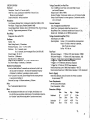
SPECIFICATIONS
Voltage Controlled Low Pass Filter
Type: 24dB/Octave cutoff slope, with variable height resonant
Keyboard
Description: 18 note C to F low-note priority
Glide Time: Linear, continuously variable from 5 msec to 2.3 sec
(Bottom to top of Keyboard)
Sample & Hold Drift: 4mV/sec maximum
peak at cutoff frequency
Range of Cutoff: 20Hz to 40kHz
Keyboard Tracking: Continuously variable, zero to full keyboard voltage
Sweep of cutoff frequency by contour generator: Continuously variable,
zero to 6.3 octaves
Modulation
Low Frequency Oscillator Rate: Continuously variable from 0.26Hz to 31 Hz
Contour Generator
Wave Shapes: Triangle, Square, Random (Sample & Hold)
Type: Retriggerable unconditional ASR
Amount (Square Wave): Oscillator, Zero to 18 Semitones; Filter, Zero to 4 Octaves
Attack Time: Continuously variable from 4 msec to 4 sec ■
Auto Trig: Triggers contour generator at LFO rate
Decay/Release Time: Continuously variable from 10 msec to 15 sec
Sustain Level: Switchable, zero or 100% of peak contour
Pitch Wheel
Range greater than ± perfect fifth
Voltage Controlled Amplifier (VCA)
Audio Output Level: OdBm
Oscillators
Operating Modes:
Number: Two
Reference Frequency:
By-Pass - VCA fully on
Osc 1 - Sawtooth, square
Octave Footages: 32', 16', 8'
Rear Panel
KB Control Voltage In:
Octave Error: .2% Maximum
KB Control Voltage In:
Scale Factor Error: 2% Maximum
S-Trigger In: Switch closure to ground triggers contour generator
Range Drift due to Temperature: 10°C to 38°C less than .05%/°C
Osc 2 Interval Range: 16 semitones, ± 3 semitones
Oscillator Synchronization
In the Sync Mode Oscillator 2's sawtooth wave can be reset by itself or by
the reset pulse from Oscillator 1. This locks the fundamental frequency
of Oscillator 2 to Oscillator 1, generating a complex waveform.
In the "Contoured" sync mode, control voltage from the contour generator
is routed only to Oscillator 2.
Contoured Sync range: 4.0 Octaves maximum, ± 2 Octaves
Noise
Type: Pseudorandom digital pink noise
■*
fully off when key is released
Low C — 32.7Hz + 0.5Hz
Osc 2 - Sawtooth, narrow rectangular (Duty Cycle 85% ± 5%)
>
Contour - VCA is controlled by contour generator
Keyed - VCA fully on when key is depressed,
Master Tuning Control: + 2.8 semitones
Waveforms:
,
1 V/Octave + 1%. Input impedance: 100Mft
1 V/Octave ± 1%. Output impedance: .O2£2
S-Trigger Out: Trigger on is switch closure to ground
V-Trigger In: 3 V in Minimum; 60K H Input impedance
V-Trigger Out: 10 Volts out; 20K Q. Output impedance
Nominal Audio Input Level: OdBm (Input impedance = 18K SI)
Nominal Audio Output Level: OdBm (Output impedance = 1K £2 unbalanced)
Burn In (Aging)
Before final calibration, units are burned in for 24 hours at ambient
of approximately 72°F
Power Requirements
24V AC External Power Supply
Power Consumption: 6 Watts
Mixer
When the Oscillator level sliders are set at 5 or higher, the Oscillators over
drive the filter input, producing a small amount of intermodulation distortion the "Overdrive11 sound. Mixer settings below 5 produce normal sound.
47
INDEX
Amplification
5
Assembly
3
Articulators
36,37
Auto Trig
Audio Generators
;
v
34, 36
31, 32
Audio In
45
Audio Out
:
4
Contour Generator
24,25
Contoured Sync
24
Controllers .
38, 39
Control Voltages
42
Filter
Cutoff Frequency
*
26
26
Emphasis
27
KB Track
28
Contour Amount
27
Glide
20, 38
Interfacing .
.-rfTx.
Procedure
'
40, 41
1
Control Voltage
40
42
Scaling
46
Range
46
Triggers (IN/OUT)
43
Cables
43
Interval
Keyboard IN/OUT
LFO
Maintenance
Master Volume
Mixer
'.."..•
Modifiers
Modulation
23
42
:
,
. . . .•
34
4
29
28,38
• 33-35
21, 22, 34
Mod Wheel
Mod Shape
Mod Rate
LFO
Routing
21» 34
21> 34
21
34
34
Oscillator 2 Interval
23, 31
Noise
Oscillators
Octaves
Osc Sync (Osc 2 to Osc 1)
29>31
22» 31
22
23> 31
Tuning
Waveform
Overdrive
Pedalboard
Pitch Wheel
Sample & Hold
Sawtooth Waveshape
Setup
Sound Charts
Specifications
20
22> 31
29>38
36> 38
21> 38
34
3^
3
y-18
4^
Sustain
Sync
25»36
23^
Square Waveshape
Tremolo
Triggers
Tuning
Interval
Rate LFO
VCA . . . ^
Vibrato
Waveforms
22, 31
34
43
20>31
23
21' 34
26
34
3^
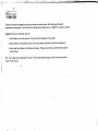
SUPPLEMENTARY INFORMATION
A Gig Bag is provided for convenient handling of the instrument.
1. Insert the stand in the long narrow pocket which runs the length of the Gig Bag.
(The stand will act as a support.)
2. The synthesizer module fits in the left side pocket of the Gig Bag.
3. The cable and power supply fit in the smaller pocket on the right side of the bag.
4. The two small straps of the Gig Bag then attach to the two strap posts located
at the top of the pedal unit.
The whole assembly can then be carried by the handle at the rear of the pedal unit.
MOOG MUSIC INC
2500 Walden Avenue
Buffalo, New York 14225
J93-045481-001
Copyright 1982 Moog Music Inc.
Printed in U.S.A. - T.G.-1000