1
&'()(
&'(("
!" " #!" !$%
!! (
!!
+,
+.+/,
+1
3
5
,
/6
%+
.
+
0
2
4
'
"
!* (
"!
7
,
86
9:9
,
0
2
,+6+:
4
#!
'
"$ !"
!% !
&'
!*)
()
'*+
$
71958,57.596&1::695195;5,796,.1,&<117857.6:=67.>1;6*775,1791;5%6,5
$
71958,57.596&1::6955;5,796,.1,&<19689>71591<1?59%57.5:1;;1=6@
8
<
AB
<
?
A+
+<
A
C
A
+
=A
+
C<
+A<+<
A
:
+A+
D
D
AA
7C++
+
+
C+
$
71958,57.596&1:9@571@955:695
AA++?
A
C++
A+.
+
1
C++
E+
,A+B@
3
8
C
&<3+
8++
+ FA
C+
C
+
$
71958,57.596&1:689>7159167.55%571:9@571:695<1?59%57.5:1;;1=6@
17.59:;5
*3+<
C<
<
?5,95:8;7195%57?89
6E
+
<5%,875,;;7.5:69559757
5%596,&8:;6@G>
11785=759<+
GA
D
8D+1;>
>
C
A,?,D+<
C
! 73
) 73+
( >
3+3
C
D
$
71958,57.596&1::695<5;5,796,.1,&19689>71591<1?59%57.5:1;;1=6@
6
C+
B3
HI
6+3*
3
D+
+
+EHI
+B
A
C*+:
+BF+
:
H:I
.+<9+
,
+5+H.95I
=+
+
+<
++
A
5%59
C
+<+
+
,
71958,57.596&1::695<851;>57;8,7=19& 17:19851%59187119@96;;
7
C
3
D
*
AD
<+<
<
++
%
A+3=
<
+
<3+
+
7
A
A
+A
<
7
J
++
D
./%+0+122234)0*
3+('5
&'
6
*+(213
!!7
()
/
1A+
A+
6
F
* 7
B3
* 7
B
5,
<6K:2"
L
,,!! *'(<,5,
< ,!!!
"*' *
LL
6
+
<
B3
+
B
+
+
,CB3
+
+
A
+
L
:
?C<M<"!!0'
LL,6
4-" 5%9
<,A<1
(( ) *--27B !"%0".
A
+
-
!"C
=+!+
5+
89:-:;<3,9$-3=()
89::>;<3,,=$-3?() C+
H
I+
B
,C
B<
!
7B
,?+A<
-
:,,97+
A
+
7B+<
B+<
<
.
A<
+
6B
A
<+B
<
+
+
9
A+
6
BA
,
B
A
,
D
K7%
-
()
'*+
$
!'
!/&'()(&'(("
%%%!
*6
)*?E3
b
!*0=$?
;5+H*IH)
&'(("I
*6
H*I
*4N
K
*) K(ND "N+
K
!*.
+
C
*7
+
A
*.C+
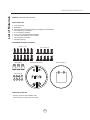
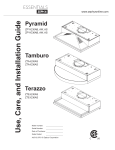
$%8
#8 x 1/2” (12)
Wire Caps (3)
3/16” x 3/8” (10)
RF Remote Control (1)
Remote Holder (1)
M4 x 6mm (8)
%%%!
*+<
*,
LIUHTXLUHGE\ORFDOFRGHV
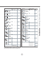
:
Equivalent number
length x used
=
Duct pieces
Total
Total
3-1/ 4” x 10” 1 Ft.
Rect.,
straight
x(
) =
Ft.
6” Round
30 Ft.
wall cap
with damper
x(
) =
Ft.
6” Round,
straight
1 Ft.
x(
) =
Ft.
6” Round,
roof cap
x(
) =
Ft.
7”-10” Round, 1 Ft.
x(
) =
Ft.
6” round to
1 Ft.
3-1/ 4” x 10”
rect.
transition
x(
) =
Ft.
3-1/ 4” x 10” 15 Ft.
Rect.90 0
elbow
x(
) =
Ft.
x(
) =
Ft.
3-1/ 4” x 10” 9 Ft.
Rect.45 0
elbow
x(
) =
Ft.
6” round to
16 Ft.
3-1/ 4” x 10”
rect.
transition
90 0 elbow
7” - 10”
Round,
90 0 elbow
15 Ft.
x(
) =
Ft.
3-1/ 4” x 10” 24 Ft.
Rect.90 0
flat elbow
x(
7” - 10”
Round,
45 0 elbow
9 Ft.
x(
) =
Ft.
3-1/ 4” x 10” 30 Ft.
Rect.
wall cap
with damper
x(
7” - 10”
30 Ft.
Round
wall cap
with damper
x(
) =
Ft.
3-1/ 4” x 10” 5 Ft.
Rect.to
6” round
transition
x(
) =
Ft.
7” - 10”
Round,
roof cap
x(
) =
Ft.
3-1/ 4” x 10” 20 Ft.
Rect.to
6” round
transition
90 0 elbow
x(
) =
Ft.
7” round to
8 Ft.
3 1/ 4” x 10”
rect.
transition
x(
) =
Ft.
) =
Ft.
15 Ft.
x(
) =
Ft.
7” round to
23 Ft.
3-1/ 4” x 10”
rect.
transition
90 0 elbow
x(
6” Round,
90 0 elbow
6” Round,
45 0 elbow
9 Ft.
x(
) =
Ft.
Subtotal column 2 =
Ft.
Subtotal column 1 =
Ft.
Total ductwork
Ft.
straight
) =
) =
Subtotal column 1 =
30 Ft.
Ft.
Ft.
Ft.
<((+!
60/:
A<
+
D ""BA
=
30 Ft.
=
@+
6+
0
Equivalent number
length x used
=
Duct pieces
@
660"
+
++
!0N
D
+
+
)0N
6
++.
+3
+
3
6A<
+F+
B
++
A+
in.
” max.
6
2 ”m
36
++
6/
4N
4
+
6/
4N
) K(ND "N+
”
36
4N
)* K(ND "N+
DE
3
+
:D
E
-"
H
+-I
A+
<
;=><
<
6
+B<
6
B
<
?
;%A!!/
+
6+<
+
6+
<
6+H
I<
+
5%59D
C
<<+<
++
D
8++
C
:
J
3A7
7
(+
6)
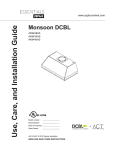
side wall cap
w/ gravity damper
side wall cap
w/ gravity damper
Soffit or crawl space
8” round or
3-1/4”x10” rect.
horizontal ducting
8” round
vertical ducting
Roof Pitch w/
Flashing & Cap
8” round
vertical ducting
B
@+
6)
$C
”
12
28
-3/
8”
,3
4-
3/8
”
3”
re
an m
te ote
nn
a
34
- 3/
8”
,4
0-
3/8
”
12”
22
”
1/2
3/4 View
(34”)12”
(40“)15”
elec.
k/o
Ø
73
/4
”
C/L
Top View
(34”)12”
(40“)15”
3-1/4”
C/L
9-7/8”
Back View
D
5-1/2”
7-3/4”
elec.
k/o
2”
1-1/2”
5-5/8”
(34”)17-1/4”
(40“)20-1/4”
10-3/8”
@)+E+
$
++21(&)'(&*KE++
)
20(+0
+1
2
02
&+16
3
:
<
A
C
++
D
+
2
+++)5
6++
+3
++))*/
7B !"%0".<
A<
+
<
-
!"C
=+!K
+
5+
&!+1/
C+
H
I+
B
,C
B
<
Cable Lock
9
@++
!!
!
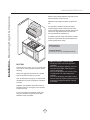
CAUTION: At least two installers are required
due to the weight and size of the insert.
')&)2)
'
+
)
3
9
AC+
A3
8
+
A
+
! ,
+
+
:6@ 6+
<
+C
HI:6@!
)
+
+ A+
+ !* (
+
):'))
+()3
( ;
+
+H4I4D K!N
H(I
H(I:6@)
$/10'+*+
60
+)&'0
60260'89:3(*
+)
L*(6+1
6'++
3
(AK
34 9434)
-1/2
”o
r
- :
C
C
3
<C
C
A
/6
A
<
C
+
cu
(AK
40
to
ut
94
4
-1/2 0)
”
-5 /
22
:6@
09*A
A
<
HLIDSSOLFDEOHI<+<E3
CABINET BACK
8in Round
5-1/2”
9”
9”
C/L
4”
11”
5-1/2”
1-1/8”
CABINET BACK
3-1/4in x 10in Rectangular
1/4”
@&
%)
"
C/L
:6@!
:6@)
>
8”
1
1
2
2
,39
A+W+
,W;+
39
AE3W+3
,WA
+
3
?
,
;
C+7
:39
A
W9
A+H!I
+
,W+
C+
-3H&'(("1I9
A+*
A+H!I
=34N
H(I
(D0
?3%+
9
+><:
@++
6%)
1
@4
+
6%)
1
1
1
2
2
,39
A+W+
,W;+
39
AE3W+3
,WA
+
3
?
,
;
C+7
:39
A
W9
A+H!I
+
,W+
C+
-3H&'(("1I9
A+*
A+H!I
=
D+
?39
A
A+H(I
)K 0ND)K4N
+
,
A
9
+
B
A
C
B
C
B3 8+EA<
A4N
) K(ND "NC
C*
C
D3 9
AC
C*
?
+
+9
AC
C
?,
+
0)
0
0
+&
&*'2
60)
%6
>):3'
+
)6:3
93 +
A
A
+
175C
A
A
:
<
H!I)K 0D)K4
-
@4
+
6%)
9
+
@4
+
6%)
>3Z+
6+
6W:
<
)* K(ND "N+
+
CC
C*
C
H4I(D0
>3Z
+
6W:
<
4N
+CC
C*
C
H(I(D0
2
1
3H!I
+
C
A+H(I
)K 0ND)K4NA
A
+ !<0
H!I
C
1
,3
W9
+
C
C
,WA
+C
A
C
4
+
6))
2
+()3'%6>)=
+()
3
-3
A
C
H4I)K 0ND)K4N<
H(I
C+
C
C*
+3
+
D
+
:
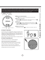
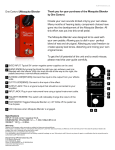
LCD Screen (speed level, delay off, filter clean,clean air)
clean mesh filter
clean air
Adjust 6 Speed Levels
LED Lights On/Dim/Off
Power / Delay Off Button
Power Button Function
Button will turn power on and off for entire insert (fan and lights).
- The insert controls will remember the last speed and light level it was turned off at.
(Example: Press Button to turn off insert when on fan Speed 4 and high lights. Press
insert will turn back on at Speed 4 and high lights level.)
Button again and the
Delay Off Button Function
- Press and hold Button for two-three seconds and the fan will turn on Speed 1. The
Graphic will illuminate. After five
minutes the fan and lights will automatically turn off.
- Pressing Button while Delay Off Function is enabled will turn the insert off and cancel the Delay Off Function.
Speed Selection Buttons
Fan Speed Decrease Button
- Press this button to decrease fan speed. 6 (burst), 5, 4, 3, 2, 1.
- If fan is on Speed 1 and this button is pressed, fan will power off.
Fan Speed Increase Button
- Press this button to increase fan speed. Fan On, 1, 2, 3, 4, 5, 6 (burst).
- If hood is off and this button is pressed, fan will turn on Speed 1.
Burst Mode
- This speed level is intended to be used as a quick burst of air extraction when excess cooking fumes and smoke are
generated. After 3 minutes the fan will automatically change to Speed 5.
Lights Button
- The Zephyr Bloom® LED Lights are two levels, High and Low.
- From off, press one time for High. LCD will show the words “lights hi” for 2 seconds then fade away.
- Press again for Low. LCD will display the words “lights lo” for 2 seconds then fade away.
- Press again to power lights off.
LCD Screen
- Displays status information, see Page 16 for more information.
=
"
@+0
Power / Delay Off
"
@
'+
Mesh Filter Clean Indicator (always enabled)
- After 30 hours of fan usage the Graphic and words “clean mesh filter” will illuminate indicating it is time to clean
the mesh filters. Graphic and words will remain illuminated until reset.
- To reset: With insert off, hold the Button for three seconds, after three seconds the
Graphic and words “clean mesh
filter” will turn off and the 30 hour timer will reset.
Clean Air Indicator
- Clean Air is a feature that turns the fan on every 4 hours for 10 minutes to remove stagnant air in the kitchen.
- To enable Clean Air Function:
- With insert off, hold the Button and
Button simultaneously for three seconds. The
Graphic and
words “clean air” will illuminate and the fan will turn on speed 1 for 10 minutes. After 10 minutes the fan
will turn off and the 4 hour timer will begin.
Graphic will remain on when Clean Air Function is enabled, even if fan is not on.
- To disable Clean Air Function:
- With insert off, hold the
Button and
Button simultaneously for three seconds until
Graphic
turns off.
- If the user changes the fan speed while the Clean Air Function is in use, the words “clean air” will turn off but the
will remain illuminated. If the user presses the Button at any time the 4 hour clean air timer will reset.
?
Graphic
/
Blower On/
Speed Selection 1
Blower On/
2 Power Off
1 Blower On / Speed Selection
Press
to power on blower and cycle through all six blower speeds.
2 Blower On / Power Off
By pressing
, the blowers will power on at the last speed setting. Press
again and the entire hood will power off, including lights.
3 Delay Off
By pressing
, the blower and lights will enter Delay Off mode. The
graphic will illuminate indicating the function is on. The blower will change to
speed 1 and shut down after 5 minutes.
4 Lights On / Dim / Off
5 Min Delay Off 3
4 Lights On/Dim/Off
Switch lights On by pressing
once, again to dim and again to switch Off.
/
79:
B+
C
+7
+
+
$
<:6@(7
+
7
+9:
D
-
:6@(
/
,
+
A+
2
+
&2')+
6&*3
8+EA<
A
HI
:6@-
9
A,-,
+A
+
+
A
9*
:6@-
B
-
"
@(
FCC Caution: To assure continued compliance, any changes or modifications not expressly approved by the party responsible for compliance could void the user’s authority to operate this equipment. (Example - use only shielded interface cables when connecting to computer
or peripheral device. This device complies with Part 15 of the FCC Rules. Operation is subject to the following two conditions. (1) This device
may not cause harmful interference, and (2) This device must accept any interference received, including interference that may cause
undesired operation. 7
A
<
+@
6
6
/
,
A
A+<
K
++
+
+
:
A
B+
+<
*A
K<
+++
3
+
60#'`
73
+
C+
+3
A
+<B
A)"
,:6
:
C
3*
+
60#'`3?/
3
+
A
+
1
! A
C
3
+
)3
C
C
)+
60#'`/
/
&'()(
&'()(
&'(("
2
%3
7*3
-"! "" )H+I !
-"! "" 2HI
-"! "" )H+I )
:6@0
60*
7+
+
E37+
E3,+
C+
++
+*
+
(5
60*
@
C
+
1
1
9
A+
:6@2*
2
!
:6@2*!
:6@2
D
$0
< 7
1
F
C
! 7
C+
+
;+
C<
+
7
A+
7
+
7
C+<
+
7
A+
:A+
! ,C
) 7
) C
( 7
( C
- 7
A
- ,+
7
C
++
D
! 7
! 7
) +
) ,+
(?
D+
C+
(
D+<C
+
+
9
- 7
A<
- ,+
7
7+
! 7
! ,C
) +
) ,+
3
J3+
!7
A;5
!,C
,+;5
! 7++
! ,
++
7
+++
+
C
J
C
!0N)0N
+
! =
++
A
! ,
E
) ?
C+
+
C
) 9
A
C+
C
+
( 7
++
( J
+
- 8+
+
+
- ,++
:
J
+3
! +
C
3
9:9
C
CCF
1
! ,++
?
9!) !A
! C
! 9
-
) 9:
) 9
+
C
-
CC
9
&0
6
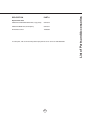
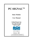
#!%#!
%ORZHU )DQ&XUYH
0RGHO $.0RQVRRQ'&%/
$&,QSXW 9+]
2XWOHW'LDPHWHULQ
%Z
KW
5"$
66(
,3D
,3B
,3?
,3=
,3:
,3,3,
,3
,
39
3D
3B
3?
3=
3:
33,
3
>39
>3D
>3B
>3?
>3=
>3:
>3>3,
>3
>
"
!-
-"
2-
""
!-
-"
2-
!""
!!-
!-"
!2-
)""
)!-
)-"
)2-
(""
(!-
(-"
(2-
-""
-!-
--"
-2-
0""
0!-
0-"
02-
2""
2ZW
Model:
AK9434AS
Voltage: 120V 60Hz
Power consumption
Total: Max. 219W @ 3.5A
Lamp:
Max. 6Wx2
Fan:
Max. 207W
Electronically Protected
Model:
AK9440AS
Voltage: 120V 60Hz
Power consumption
Total: Max. 225W @ 3.6A
Lamp:
Max. 6Wx3
Fan:
Max. 207W
Electronically Protected
U
V
W
V01
U
V
W
5A 250V
AC-N
ON/OFF DOWN
U
V
V01
W
UP
LAMP
U
V
W
5A 250V
AC-N
ON/OFF DOWN
,>
AC-L
UP
AC-L
LAMP
2!-
2-"
%b
)+(
%
&'()(K&'(("?E:<;+HI
-"! "" )
&'()(?E:<HI
-"! "" 2
9:9
,
("""""-
7
<A
KK
44444"4)04
,
!'%
++
%
STAPLE YOUR RECEIPT HERE
Proof of the original purchase
date is needed to obtain
service under warranty
Limited Warranty
TO OBTAIN SERVICE UNDER WARRANTY OR FOR ANY SERVICE RELATED QUESTIONS, please call:
1-888-880-8368
Zephyr Corporation (referred to herein as “we” or “us”) warrants to the original consumer purchaser (referred to herein
as “you” or “your”) of Zephyr products (the “Products”) that such Products will be free from defects in materials or workmanship as follows:
Three Year Limited Warranty for Parts and LED lamps: For three years from the date of your original purchase of the
Products, we will provide, free of charge, Products or parts to replace those that failed due to manufacturing defects.
We may choose, in our sole discretion, to repair or replace parts before we elect to replace the Products.
One Year Limited Warranty for Labor: For one year from the date of your original purchase of the Products, we will
provide, free of charge, the labor cost associated with repairing the Products or parts to replace those that failed due to
manufacturing defects. After the first year from the date of your original purchase, you are responsible for all labor costs
associated with this warranty.
Warranty Exclusions: This warranty covers only repair or replacement, at our option, of defective Products or parts
and does not cover any other costs related to the Products including but not limited to: (a) normal maintenance and
service required for the Products and consumable parts such as metal and carbon filters and fuses; (b) any Products or
parts which have been subject to freight damage, misuse, negligence, accident, faulty installation or installation contrary
to recommended installation instructions, improper maintenance or repair (other than by us); (c) commercial use of the
Products or use otherwise inconsistent with its intended purpose; (d) natural wear of the finish of the Products or wear
caused by improper maintenance, use of corrosive and abrasive cleaning products, pads, and oven cleaner products;
(e) chips, dents or cracks caused by abuse or misuse of the Products; (f) service trips to your home to teach you how to
use the Products; or (g) damage to the Products caused by accident, fire, floods or act of God. If you are outside our
service area, additional charges may apply for shipping costs for warranty repair at our designated service locations and
for the travel cost to have a service technician come to your home to repair, remove or reinstall the Products. After the
first year from the date of your original purchase, you are also responsible for all labor costs associated with this
warranty.
Limitations of Warranty. OUR OBLIGATION TO REPAIR OR REPLACE, AT OUR OPTION, SHALL BE YOUR SOLE
AND EXCLUSIVE REMEDY UNDER THIS WARRANTY. WE SHALL NOT BE LIABLE FOR INCIDENTAL, CONSEQUENTIAL OR SPECIAL DAMAGES ARISING OUT OF OR IN CONNECTION WITH THE USE OR PERFORMANCE OF
THE PRODUCTS. THE EXPRESS WARRANTIES IN THE PRECEDING SECTION ARE EXCLUSIVE AND IN LIEU OF
ALL OTHER EXPRESS WARRANTIES. WE HEREBY DISCLAIM AND EXCLUDE ALL OTHER EXPRESS WARRANTIES FOR THE PRODUCTS, AND DISCLAIM AND EXCLUDE ALL WARRANTIES IMPLIED BY LAW, INCLUDING
THOSE OF MERCHANTABILITY AND FITNESS FOR A PARTICULAR PURPOSE. Some states or provinces do not
allow limitations on the duration of an implied warranty or the exclusion or limitation of incidental or consequential damages, so the above limitations or exclusions may not apply to you. To the extent that applicable law prohibits the exclusion of implied warranties, the duration of any applicable implied warranty is limited to the same two-year period
described above. Any oral or written description of the Products is for the sole purpose of identifying the Products and
shall not be construed as an express warranty. Prior to using, implementing or permitting use of the Products, you shall
determine the suitability of the Products for the intended use, and you shall assume all risk and liability whatsoever in
connection with such determination. We reserve the right to use functionally equivalent refurbished or reconditioned
parts or Products as warranty replacements or as part of warranty service. This warranty is not transferable from the
original purchaser and applies in the United States and Canada.
To Obtain Service Under Limited Warranty: To qualify for warranty service, you must: (a) notify us at the address or
telephone number stated below within 60 days of the discovery of the defect; (b) give the model number and part identification number and serial number; and (c) describe the nature of any defect in the Product or part. At the time of the
request for warranty service, you must present evidence of your proof of purchase and proof of the original purchase
date. If we determine that the warranty exclusions listed above apply or if you fail to provide the necessary documentation to obtain service, you will be responsible for all shipping, travel, labor and other costs related to the services.
Please check our website for any revisions, www.zephyronline.com.
Zephyr Corporation Service Department, 2277 Harbor Bay Parkway, Alameda, CA 94502 1-888-880-8368
MAR11.0201