1
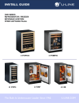
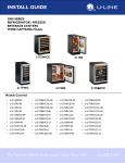
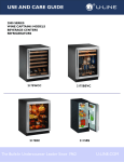
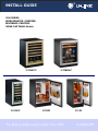
®
INSTALL GUIDE
2000 SERIES
REFRIGERATOR / FREEZER
BEVERAGE CENTERS
WINE CAPTAIN® Models
2175WCC
2115WC
2175BEVC
2175RF
The Built-In Undercouter Leader Since 1962
2115R
U-LINE.COM
1 Table of Contents
Safety Precautions
Safety Alert Definitions.........................................................................................................................................1
General Precautions ..............................................................................................................................................1
Inspect & Plan
Product Registration .............................................................................................................................................2
Models Covered.....................................................................................................................................................2
Tools / Material Required ....................................................................................................................................2
Exterior Cleaning ...................................................................................................................................................2
Black and White Models:........................................................................................................................... 2
Stainless Models:.......................................................................................................................................... 2
Prepare Site
Electrical Specifications .........................................................................................................................................3
Cut-Out Dimensions.............................................................................................................................................3
2115 Series ................................................................................................................................................... 3
2175 Series ................................................................................................................................................... 3
2275 Series ................................................................................................................................................... 3
Product Dimensions
2115R 2115WC(OL) & 2175RC Series................................................................................................. 4
2175BEV & 2175WC 2275ZWC Series................................................................................................ 5
Door Swing Dimensions
Other Site Requirements .....................................................................................................................................6
Side-By-Side Installation............................................................................................................................. 6
Power Supply ............................................................................................................................................... 6
Environmental Requirements ................................................................................................................... 6
Self-Closing Doors
Door Alignment and Adjustment.......................................................................................................................7
Door Reversability.................................................................................................................................................7
Reversing the door ................................................................................................................................................7
Wood Trim Finishing
Staining and final finish application: ......................................................................................................... 9
Final finish-only application: ...................................................................................................................... 9
Door Panel Installation
Custom 1/4'' Thick Door Panel Insert ............................................................................................................10
Door Panel Preparation.......................................................................................................................... 10
Panel Dimensions. .................................................................................................................................... 10
Door Panel Installation ........................................................................................................................... 10
Wood Grille Overlay
Grille Overlay .......................................................................................................................................................11
Preparation ................................................................................................................................................ 11
Installation.................................................................................................................................................. 11
Overlay Frame
Frame Preparation ................................................................................................................................... 14
Prepare The New Overlay Panel ......................................................................................................... 15
Attaching the overlay panel ................................................................................................................... 15
Assembling Door To Cabinet ............................................................................................................... 16
Installation
Leveling Information ............................................................................................................................................17
Installation..............................................................................................................................................................17
Relocating the Shelves............................................................................................................................. 17
Installation Troubleshooting.................................................................................................................. 17
2 Safety Precautions
General Precautions
IMPORTANT
• PLEASE READ all instructions before installing,
operating, or servicing the appliance.
• Proper installation procedures must be followed when
completing an installation or relocation of a unit.
Consult the installation guide before any installation
begins. U-Line contact information appears on the rear
cover of this guide.
• This unit requires connection to a dedicated 15 Amp
grounded (three-prong), polarized receptacle, installed
by a qualified electrician, compliant with applicable
electrical codes.
Safety Alert Definitions
Throughout this guide are safety items labeled with a Danger,
Warning or Caution based on the risk type:
Use this appliance for its intended purpose only and follow these
general precautions with those listed throughout this guide:
DANGER
RISK OF CHILD ENTRAPMENT. Before you throw away your
old refrigerator or freezer, take off the doors and leave shelves
in place so children may not easily climb inside.
WARNING
SHOCK HAZARD - Electrical Grounding Required.
• Never attempt to repair or perform maintenance on
the unit until the electricity has been disconnected.
• Never remove the round grounding prong from the
plug and never use a two-prong grounding adaptor.
• Altering, cutting of power cord, removal of power
cord, removal of power plug, or direct wiring can
cause serious injury, fire and or loss of property and
or life, and will void the warranty.
• Never use an extension cord to connect power to the
unit.
• Always keep your working area dry.
WARNING
DANGER
Danger means that failure to follow this safety statement will
result in severe personal injury or death.
Install provided Anti-Tip kit on all Wine Captain
Models and Glass Door Refrigerators. Serious personal
injury could occur.
CAUTION
WARNING
• Use care when moving and handling the unit. Use gloves
to prevent personal injury from sharp edges.
• If your model requires defrosting, DO NOT use an ice
pick or other sharp instrument to help speed up
defrosting. These instruments can puncture the inner
lining or damage the cooling unit. DO NOT use any type
of heater to defrost. Using a heater to speed up
defrosting can cause personal injury and damage to the
inner lining.
Warning means that failure to follow this safety
statement could result in serious personal injury,
property or equipment damage.
CAUTION
Caution means that failure to follow this safety statement
may result in minor or moderate personal injury, property
or equipment damage.
IMPORTANT
• Do not lift unit by door handle.
• Never install or operate the unit behind closed doors.
Be sure front grille is free of obstruction. Obstructing
free airflow can cause the unit to malfunction and will
void the warranty.
• Failure to clean the condenser every six months can
cause the unit to malfunction. This could void the
warranty.
• Allow unit temperature to stabilize for 24 hours before
use.
• Do not Block any internal Fans
Use only genuine U-Line replacement parts. Imitation
parts can damage the unit, affect its operation or
performance and may void the warranty.
U-Line Safety Precautions
1
Tools / Material Required
3 Inspect & Plan
• Screwdrivers — slotted and Phillips head
(Models ending in OL Only)
• 3/4” overlay frame material
• Cutting Tools
Product Registration
• Drill & Drill Bits
You have received a carton containing your U-Line Refrigerator,
Refrigerator Freezer, Beverage Center or Wine Captain® unit
with a package inside containing a Use and Care Guide, a Product
Registration Card, and a water line kit. Please complete and mail
the Product Registration Card or register online at www.ULineService.com. Once your unit is installed, keep the Use and
Care Guide and this Installation Guide in a safe place for future
reference.
(Optional Door Panel on 2115R(F) or 2175R(F) Black or White Models)
Models Covered
• 220 grit Sandpaper
This installation guide covers the following models.
• 280 grit Sandpaper
• 1/4” thick door panel material
• Cutting Tools
(Optional WC & BEV Wood Trim Finishing)
• Minwax® Water-Based Wood Stain
• Minwax® Polycrylic® Protective Finish
• Foam Applicator and / or Synthetic Bristle Brush
(Optional Overlay kits for Non-OL models)
U-2115RB-00
U-2175RCGS-01
U-2115RS-00
U-2175RCS-00
U-2115RS-01
U-2175RCS-01
U-2115RSOD-00
U-2175RCW-00
U-2115RSOD-01
U-2175RFB-00
U-2115RW-00
U-21575RFS-01
U-2115WCOL-00
U-2175RFW-00
U-2115WCS-00
U-2175RSOD-00
Model
Panel Kit (Black)
Panel Kit (White)
2115R
U-OL2115B
U-OL2115W
2175R
U-OL2175B
U-OL2175W
2175RF
U-OL2175B
U-OL2175W
Exterior Cleaning
Black and White Models:
• Black and White surfaces may be cleaned with a mild detergent
and warm water solution. Do not use solvent-based or abrasive
cleaners. Use a soft sponge and rinse with clean water. Wipe
with a soft, clean towel to prevent water spotting.
U-2115WCS-01
U-2175RSOD-01
U-2175BEVCOL-00
U-2175WCCOL-00
U-2175BEVCS-00
U-2175WCCS-00
Stainless Models:
U-2175BEVCS-01
U-2175WCCS-01
U-2175RCB-00
U-2275ZWCOL-00
• Stainless door panels, handles and frames can discolor when
exposed to chlorine gas, pool chemicals, salt water or cleaners
with bleach.
U-2175RCGOL-00
U-2275ZWCS-00
U-2175RCGS-00
U-2275ZWCS-01
• Keep your Stainless unit looking new by cleaning with a good
quality all-in-one stainless steel cleaner/polish on a monthly
basis. For best results use Claire Stainless Steel Polish and
Cleaner, which can be purchased from U-Line Corporation
(Part numbers 173348).
• Do not clean with steel wool or abrasive pads.
• Do not use cleaners that are not specifically intended
for stainless steel on stainless surfaces (this includes
glass, tile and counter cleaners).
• If any surface discolors or rust appears, clean it quickly with
Bon-Ami or Barkeepers Friend Cleanser and a non-abrasive
cloth. Always clean in the direction of the grain. Always finish
this process with Claire Stainless Steel Polish and Cleaner or
comparable product to prevent further problems.
WARNING
Rust that is allowed to linger can penetrate into the
surface of the stainless steel and complete removal of
the rust may not be possible.
U-Line Inspect & Plan
2
4 Prepare Site
2175 Series
Your U-Line product has been designed for either free-standing or
built-in installation. When built-in, your unit does not require
additional air space for top, sides, or rear. However, the front grille
must NOT be obstructed and clearance is required for an
electrical connection in the rear.
Follow the cut-out drawing The 24-1/4" width allows 1/4" for ease
in installation and removal of the unit. 24" is the cabinet depth in
most installations.
IMPORTANT
• Unit can NOT be installed behind a closed cabinet door.
Electrical Specifications
WARNING
24"
SHOCK HAZARD — Electrical Grounding Required.
34-1/4"
to
35-1/8"
• Never remove the round grounding prong from the
plug and never use a two-prong grounding adapter.
7"
4"
• Never use an extension cord to connect power to the
unit.
24-1/4"
IMPORTANT
Electrical installation must observe all state and local
codes. This unit requires connection to a grounded (threeprong), polarized receptacle that has been placed by a
qualified electrician.
The unit requires a grounded and polarized 115 VAC, 60 Hz, 15A
power supply (normal household current). An individual, properly
grounded branch circuit or circuit breaker is recommended. GFCI
(ground fault circuit interrupter) is usually not required for fixed
location appliances and is not recommended for your unit because
a GFCI could be prone to nuisance tripping. However, be sure to
consult your local codes.
2275 Series
Follow the cut-out drawing The 24-1/4" width allows 1/4" for ease
in installation and removal of the unit. 24" is the cabinet depth in
most installations.
See below for recommended receptacle location
Cut-Out Dimensions
24"
2115 Series
7”
1-1/2”
24-1/4”
34-1/8"
to
35"
24”
7"
1-1/2"
15-1/4"
Follow the cut-out drawing. The 15-1/4" width allows 1/4" for ease
in installation and removal of the unit. 24" is the cabinet depth in
most installations.
Prepare Site
3
2115R 2115WC(OL) & 2175RC
Series
5 Product Dimensions
2115R Series
2115WC / 2115WCOL Series
21175RC/RCG/RF Series
23-1/4"
23-1/16"
23-1/4"
34-1/8"
34-1/8"
3-13/16”
15"
3-13/16”
34-1/8"
15”
3-13/16”
2115R Black / White Models
24"
2115WCS Stainless Steel Models
2175R(C)(F) Black and White Models
23-1/2"
23-1/8”
23-1/16”
34-1/8"
34-1/8"
34-1/8"
3-7/8”
3-13/16”
15"
15"
2115RS Stainless & Outdoor Models
2115WCOL Wood Overlay Models
*Not Including Wood Overlay Panel
3-13/16”
24"
2175R(C)(F)S(G) Stainless & Out Door Models
22-5/8”
34-1/8"
3-13/16”
24"
2175R(C)(F)S Overlay Models
Product Dimensions
4
2175BEV & 2175WC 2275ZWC Series
2175BEVC Series
2175WCC Series
23-1/4”
24"
3-13/16”
2175WCCS Stainless Steel Models
22-5/8"
2175BEVCOL Wood Overlay Models
24”
2275ZWCS Stainless Steel Model
22-5/8”
22-5/8"
34-1/8”
34 - 1/8"
34 - 1/8”
23 15-16”
34-1/8”
34 - 1/8"
3 - 13/16”
23 15-16”
2175BEVCS Stainless Steel Models
3 - 13/16”
23-1/4””
23-1/4”
34 - 1/8"
3 - 13/16”
2275ZWC Series
3 - 13/16”
24"
2175WCCOL Wood Overlay Models
Product Dimensions
3-13/16”
24”
2275ZWCOL Wood Overlay Model
5
6 Door Swing Dimensions
2175WC Models
Wall
2115R Models
Wall
2" Min.
Wall
Wall
1/4" Min.
2" Min.
21"
21"
21"
21"
25-1/2"
90
Door Swing
16-1/2"
90
Door Swing
16-1/2"
25-1/2"
90
Door Swing
Black, White and Wood Overlay
Stainless Steel
90
Door Swing
Stainless Models
Black and White Models
2115WC Models
Wall
Wall
1/4" Min.
Units have a zero clearance for the door to open 90°. Stainless
Steel models require 2 1/8” door clearance to accommodate the
handle if installed next to a wall.
Other Site Requirements
2" Min.
Side-By-Side Installation
21"
21"
For a complete refreshment center, install two units side by side:
Cut-out width for a side-by-side installation is the total of the
widths listed under Cut-Out Dimensions in each unit’s Installation
Guide.
16-1/2"
16-1/2"
No trim kit is required. However, 1/4-inch space needs to be
maintained between the units to ensure unobstructed door swing.
90
Door Swing
90
Door Swing
Units must operate from separate, properly grounded electrical
receptacles placed according to each unit’s Electrical Specifications
Requirements
Stainless Steel
Black, White and Wood Overlay
2175R(F) & 2275WC Models
Wall
Wall
1/4" Min.
Power Supply
2" Min.
21"
21"
The unit requires a grounded and polarized 115 VAC, 60 Hz, 15A
circuit (normal household current). See Electrical Specifications.
Environmental Requirements
25-1/2"
90
Door Swing
25-1/2"
90
Door Swing
Black and White
If the ambient temperature is expected to drop below 45°F (7°C),
drain all water from the unit to prevent freezing damage, which is
not covered by the warranty.
Stainless Steel
2175BEV
Wall
1/4" Min.
Wall
2" Min.
21"
21"
25-1/2"
90
Door Swing
Wood Overlay
25-1/2"
90
Door Swing
The units are designed to operate between 50°F (10°C) and 100°F
(37°C). High ambient temperatures (100°F [37°C] or higher) may
reduce the unit’s ability to reach low temperatures and may also
reduce the ice production rate for those models with icemakers.
For best performance, keep the unit out of direct sunlight and
away from heat generating equipment.
For best performance and life outdoors, place under a counter or
provide shelter of some kind.
In climates where high humidity and dew points are present,
condensation may appear on outside surfaces. This is considered
normal. The condensation will evaporate when the humidity drops.
Stainless Steel
Door Swing Dimensions
6
7 Self-Closing Doors
Door Alignment and Adjustment
Align and adjust the door if it is not level, or is not sealing properly.
If the door is not sealed the unit may not cool properly, or
excessive frost may form in the interior.
IMPORTANT
• Properly aligned, the door’s gasket should be firmly in
contact with the cabinet all the way around the door
(no gaps). Carefully examine the door’s gasket to ensure
that it is firmly in contact with the cabinet. Also make
sure the door gasket is not pinched on the hinge side of
the door.
• The door will not be flush with the top of the cabinet.
The top edge of the door will be 1/8 in. (3.175 mm)
below the cabinet top.
1/8"
(3.175 mm)
4
5. After adjustment is complete, remove the door closers from the
bottom hinge, clean thoroughly and apply petroleum jelly to the
mating surfaces of the closers. Be sure that pins on closers align
with holes in the door and bottom cabinet hinge plates. Mount
door and install top hinge pivot pin.
Door Reversability
Location of the unit may make it desirable to mount the door on
the opposite side of the cabinet.
Models with black and white doors are field-reversible.
Stainless steel models must be ordered right- or left-hand hinged.
Reversing the door
To align and adjust the door:
1. Compare the top edge of the door (opposite the hinges) to the
top edge of the cabinet and note the type (up or down) of
adjustment needed.
1
2
3
2. Remove the top hinge pivot pin with a Phillips screwdriver and
lift door off bottom hinge pin. Be careful not to lose the door
closer insert sets.
3. Turn the door upside down and inspect the hinge plate mounting
holes. The plate has slotted mounting holes. Loosen but do not
remove the two hinge plate screws(1).
4. If door edge opposite the hinges needs to move up, move plate
toward outside of door(2). If door edge needs to move down,
move plate toward inside of door(3). Repeat until top edge of
door is parallel with top of cabinet and tighten screws (1)
securely.
The Hinge hardware will be removed and reinstalled on the
opposite side of the cabinet.
The top hinge hardware will be reinstalled on the bottom of the
opposite side of the cabinet.
The bottom hinge hardware will be reinstalled on the top of the
opposite side of the cabinet.
U-Line Self-Closing Door Alignment and Reversal
7
To reverse the door:
Remove existing bottom hinge.
Remove the existing bottom hinge (three screws) (2).
3
1
Reinstall hinge to top opposite.
Install the hinge just removed from the bottom to the TOP
opposite side of the cabinet (three screws) (2).
Reinstall Hole Plugs.
Install plastic screw plugs (three each, top and bottom) (3) into
holes where hinge hardware was removed.
2
Remove door:
1
1. Hold door to keep it from falling.
2. Remove hinge screw pin (1) from top hinge using a Phillips
screwdriver.
3. Remove door by tilting forward and lifting door off bottom hinge
closer inserts.
4. Reinstall hinge screw pin (1) into top hinge using a Phillips
screwdriver.
Remove hole plugs.
NOTCH
Remove plastic screw plugs (three each, top and bottom) (3)
from new hinge location. Save for reinstallation later.
5
Remove existing top hinge.
Remove existing top hinge (three screws) (2).
Prepare door for reinstallation.
1. Remove plastic hole plug from top of door handle and reinstall
on opposite side.
2. With bottom of door facing up, remove pivot plate (5) (two
screws).
3. Flip over and install pivot plate on opposite side of door. Ensure
notch in plate faces center.
Install Door.
4
ULI
1. Hold door upright and tilted forward.
4
2. Lift door on to bottom hinge closer inserts.
Reinstall hinge to bottom opposite.
3. Tilt door forward into position.
1. Install the hinge just removed from the top to the BOTTOM
opposite side of the cabinet (three screws) (2).
4. Hold door to keep it from falling.
2. Remove the two door closer inserts (4) from the existing
bottom hinge.
3. Install door closer inserts as shown on the new bottom hinge
(4).
5. Reinstall hinge screw pin (1) into top hinge using a Phillips
screwdriver.
Align and adjust the door:
Align and adjust the door, see DOOR ALIGNMENT AND
ADJUSTMENT above.
U-Line Self-Closing Door Alignment and Reversal
8
8 Wood Trim Finishing
Staining and final finish application:
IMPORTANT
WARNING
To prevent permanent damage to the inner liner of the
unit, the wire rack wood trim MUST be removed from
the unit for staining and/or finishing. Allow stain/finish
to dry thoroughly (at least 24 hours) in accordance with
the stain/finish manufacturer’s instructions, prior to reinstalling the wood trim inside the cabinet of the unit.
Failure to do so may cause the inner liner of the unit to
have a permanent odor, which is not covered by the
warranty.
IMPORTANT
• Your model may contain an electronic display panel in
the lowest level trim piece. After removing the trim
screws and gently pulling the trim from its location, a
wiring harness connector will become visible. Unplug
the connector and remove the trim from the interior.
• Glass in door is tinted. Stain may look darker when
door is closed.
Removing Wire Racks
1. Grasp the end of the rack, and gently slide it out until it stops.
2. Remove any bottles stored on the rack.
3. Press the left rack release lever (see above) down, and at the
same time, lift the corresponding right rack release lever up, and
pull the rack out until it is free of the tracks and the cabinet.
4. Do not remove the track side rails from the cabinet.
To insert a rack in the cabinet:
DO NOT use oil-based stains on wood trim. Vapors from
oil-based stains will permanently penetrate the liner and
will not dissipate over time.
1. Remove all screws securing wood trim to interior parts, and
remove the trim from the cabinet interior.
2. Lightly sand and clean wood.
3. Apply Minwax® Water-Based Wood Stain to wood with a
synthetic bristle brush or a foam applicator. Allow stain to
penetrate about three minutes. Before the stain is dry, take a
stain dampened rag and remove any excess stain remaining.
Wipe towards the grain with medium pressure to achieve the
desired stain color.
4. After two hours, repeat step 2. This will even out the color of
the wood.
5. Allow stain to dry for a minimum of three hours before applying
the final finish.
6. If desired, sand the wood with very fine sandpaper to smooth
the surface after staining.
7. Remove all dust from the wood, and apply one coat of Minwax®
Polycrylic® Protective Finish using a synthetic bristle brush to
the wood. Apply this finish in a thin coat following towards the
grain. Apply the finish to the back and sides of the wood first,
and allow it to dry for two hours. Apply the finish to the front
side of the wood next, and allow it to dry for two hours. Sand
with very fine 220 grit sandpaper. Apply two morel coats of
finish in the same manner, but do not sand the trim after
applying the final third coat.
8. Allow the final coat to dry for 24 hours before reinstalling the
trim to the cabinet interior parts.
Final finish-only application:
1. Remove all screws securing wood trim to interior parts, and
remove the trim.
2. Lightly scruff sand the wood trim with 280 or finer grit
sandpaper.
3. Remove sanding dust with a clean, dry cloth.
1. Align the left and right rack channels with the tracks in the
cabinet, and ensuring an even track engagement on both sides,
gently push the rack into the cabinet until it stops.
Before reloading the rack, ensure proper operation of the travel
stops in the left and right track rails by pulling the rack out gently
until it completely stops.
4. The factory-applied seal is compatible with almost all finishes. A
low odor, water clean up, quick-drying finish such as Minwax®
Polycrylic® Protective Finish is recommended (Minwax®
Polycrylic® is an ultra fast-drying water-based finish). Apply a
thin coat of a clear, protective finish, following the container
label directions.
5. Lightly sand and reapply if desired.
Allow the final coat to dry for 24 hours before reinstalling
the trim to the cabinet interior parts.
U-Line Wood Trim Finishing
9
9 Door Panel Installation
Custom 1/4'' Thick Door Panel Insert
Door Panel Preparation
A custom door panel may be inserted into the doorframe. Custom
door panels can be flat or raised, as long as the maximum panel
thickness, where inserted into the door reveal (channel), is no
more than 1/4" thick. For raised panels, the depth of the reveal is
1/4" on all four sides.
IMPORTANT
Raised panels will reduce the door’s 90° swing/zero
clearance if the unit is installed next to a wall or similar
type of structure.
3. Remove the two outside screws holding
door handle. Slightly separate door
handle from door.
4. Pull handle up and off.
5. Slide custom door panel insert into 1/4inch channel in door front.
IMPORTANT
Use care not to damage magnet, located on door bottom,
when installing door insert. Do not set door on bottom
edge when pushing insert into place.
6. Holding door gasket out of the way, replace handle on door,
making sure it is seated properly on insert and that screw holes
line up.
7. Install two small screws removed in Step 3.
Panel Dimensions.
8. Starting at the corners and working inward, push door gasket
into place on door.
The door panel must not weigh more than 20 lbs.
Model
Width
Height
2175R(C)(F)
23 1/32”
27 11/16”
2115R(C)(F)
14 1/32”
27 11/16”
9. Place door on bottom hinge pin and install upper hinge screw.
Door Panel Installation
Install the insert as follows:
CAUTION
Use care when handling the insert. Insert edges may be
sharp.
1. Remove top hinge screw pin with Phillips head screwdriver.
Remove door by tilting forward and lifting off bottom hinge
pin.
2. Pull door gasket out of groove (top edge of door only). Start in
the middle and pull outward, moving toward the edge . This may
take some force.
U-Line Door Panel Installationl
10
You may also mount your overlay to your grille using hook and
loop type fasteners. U-Line recommends using 3M® Dual lock®
fasteners. To mount your overlay using a hook and loop fastener
follow the instructions below.
10 Wood Grille Overlay
Grille Overlay
Your models grille is designed to accept a wood grille overlay. An overlay may be used to compliment a door overlay
and provides a seamless look for your surrounding decor.
Follow the instructions below to prepare and install your
grille overlay. Be sure to read over this chapter completely
before beginning.
Preparation
1. Read the instructions provided with your hook and loop
fastener carefully.
2. Apply hook and loop fastener system to the back of the overlay
and front of the grille. Use the shaded areas in the diagram
below for application location.
24 Inch Models
Application
Area
Wood Overlay
WARNING
Back
The grille overlay MUST have venting as shown in the
drawing below. Failure to have proper venting can
result in damage to your model.
Grille
Front
WARNING
The grille overlay may only be installed on indoor units.
1. Prepare your overlay using the dimensions provided in the
figure on page 12 for 24 inch models and page 13 for 15 inch
models. If using a hook and loop style mount, drill hole A will
not be used.
15 Inch Models
Application
Area
Wood Overlay
Back
2. If desired, stain and finish your grille to match your surrounding
decor. Follow the stain manufacturers instructions to apply stain
to your overlay.
Grille
Installation
Front
IMPORTANT
The wood overlay grille must be installed in such a
manner that the grille assembly can still be removed from
the unit.
3. Carefully align the wood overlay with the grille and press into
position.
Screw Mount (Recommended)
1. Remove the grille from your unit by removing the two
mounting screws. See below.
Remove Screw
Remove Screw
2. Lay the back of your grille overlay onto the front of the grille.
Make certain the screw holes and vents are aligned.
3. Slide each of the screws removed in step 1 through the grille
overlay and grille.
4. Mount your new overlay onto your unit by screwing the overlay
back onto the base of your unit.
Hook and Loop Fastener Mount
U-Line Grill Overlay Installation
11
1/4
1/2
3-3/32
2-1/8
11/64
U-Line Grill Overlay Installation
23-7/8
19-5/8
22-7/8
5/16
8-1/2
10-5/16
Grille Overlay Dimensions 24 Inch Models
FULL R
1/2
5/16
TYP 2X
1/2
TYP 3X
(7/16 )
Grille Drawing 24 inch
12
1/4
1/2
3-3/32
2-1/8
11/64
U-Line Grill Overlay Installation
14-7/8
10-5/8
13-7/8
.275
4-5/32
5-29/32
FULL R
Grille Overlay Dimensions 15 Inch Models
1/2
5/16
TYP 2X
1/2
TYP 3X
(15/32 )
Grille Drawing 15inch
13
1. Use the following instructions to create or have a wood
overlay panel created for you Wine Captain® or beverage
Center model as shown below.
11 Overlay Frame
Frame Preparation
2115WCOL 2175WCCOL & 2175BEVCOL Models Only
2. Drill holes for pivot pins, upper door hinge and lower door
hinge as shown
An overlay frame covers the door frame to give a built-in
appearance. Appropriate hardware and a copy of these
instructions will be included with the unit.
IMPORTANT
The thickness of the overlay panel must be 3/4”
Right-hand
isometric view
shown.
Opposite
for left-hand
3/8”
See Detail A
9/32”
NOTE: Final component
is only a picture frame.
No panel inside of rails.
(Excludes -60 Models)
NOTE: Front view of
wood panel with
Dim. B
A
right-hand hinge shown
(mirror image
for left-hand hinge)
Detail A
Scale 2:1
Door top
Ø 3/16” x 11/16” deep
A
Detail C
Scale 2:1
2-1/4”
Door bottom
Ø 3/8” x 1/4” deep
Chamfer 1/32” x 45°
3/4”
9/32
Section A-A (Excludes -60 Models)
Scale 2:1
Typ 4 places
3/4”
Dim. A
(See Table)
See Detail C
Dimension B Table
Dimension A Table
Model
Dimension A
Toe Kick
Dim. B
Toe Kick
Dim. B
2115WCOL
14-3/4”
3-3/4”
29-3/4”
4 1/4”
29-3/8”
2175BEVCOL
23-3/4”
3-7/8”
29-3/4”
4-3/8”
29-1/4”
2175WCCOL
23-3/4”
4”
29-5/8”
4-1/2”
29-1/4”
2275ZWCOL
23-3/4”
4-1/8”
29-1/2”
Overlay Frame
14
Prepare The New Overlay Panel
IMPORTANT
The overlay door panel must not weigh more than 20 lbs.
The thickness of the door panel must be 3/4”
1. Place a towel, or similar, soft non-marking material out on a flat
clean surface. Be sure the material is large enough to have the
wood panel not touch the hard mating surface.
2. Lay the wood panel out with the front side of the wood facing
down.
3. Cut the foam tape in to four pieces, two pieces the width of the
overlay and two pieces the height of the overlay.
4. Remove adhesive protection strip from one piece of the cut
foam and align the edge of the foam tape to the inside edge of
the overlay as shown, adhering the foam tape to the overlay. See
Below
2. Carefully lay the door over the wood panel, making sure door is
oriented correctly (top of door with top of wood overlay).
3. Pull door gasket out of the groove completely. Start in the
middle and pull outward, moving towards the corners (See
Below). This may take some force, but be careful not to cut or
rip the gasket.
5. Trim each piece of tape immediately after applying it to the
overlay. Do not allow any overlapping of the foam tape. Damage
to the overlay can occur is the foam tape is not trimmed
correctly.
6. If required, attach any optional cabinet hardware to the wood
panel at this time. If an optional cabinet handle is installed, make
sure the mounting screw heads are below (countersunk) the
back surface of the overlay.
Note: After attaching the optional cabinet hardware, additional
supports may be needed to keep panel flat for next steps.
Attaching the overlay panel
1. Remove the top hinge pivot pin with a Phillips screwdriver and
lift the door off bottom hinge pin. Be careful not to lose the
door closer insert sets. Save pivot pin for use later. See figure
in next column.
4. After the gasket has been removed, place it on a clean, flat
surface.
5. Secure the door to the back of the wood overlay using tape on
all four corners. Make sure all four edges are aligned. (See figure
on next page)
Overlay Frame
15
will not align correctly. (Sometimes it is helpful to open the door
180° to have the closer and pivot align correctly).
DOOR FRAME
11. Holding the door in the closed position, install the pivot post
through the top hinge into the top pivot plate. Tighten securely
with a Phillips screwdriver, making sure post is seated fully.
TAPE
12. Adjusting the door as needed.
TOP OF
OVERLAY
#6 x 1” Pan Head Screws
(10 Total)
BOTTOM OF
OVERLAY
Top Of Panel
Tape
ULIN_0418_A
6. Use the door
frame holes as
a guide to
lightly punch
pilot holes for
the #6x1” pan
head screws
Door closers
7. Attach the
door to the
overlay using
#6x1” wood
screws.
If you decide to
drill pilot holes,
remove the
wood overlay
from the door,
and do not use
a drill larger then 7/64”. Be sure not to drill deeper then 3/
8”. The door frame and wood overlay must be aligned
properly or the door will not operate correctly.
Depending on installation
bottom of overlay may NOT
align with bottom of door
Note: After attaching the wood to the door, double check the
bottom pivot hole location. If the hole in the pivot bracket is
covered by any wood, chase through the hole with a 11/32” drill to
open hole in door panel. DO NOT drill deeper than 1/4”.
Assembling Door To Cabinet
8. Starting at the corners and working toward the center, push the
door gasket back into place. Make sure the gasket is fully seated
on all four sides and corners.
9. Check the closure assembly on the bottom hinge to be sure it is
seated correctly in the bosses in the hinge.
10. Position door over closer. Be sure the door hinge plate holes
align with the bosses on the closer (see below). Failure to do so
will result in the door not sitting in the proper position and door
Overlay Frame
16
Installation
12
12 Installation
1. Plug in the powercord.
Leveling Information
2. Gently push the unit into position. Be careful not to kink the
water supply line or entangle the electrical cord.
It is recommended that the unit is level.
1. Use a level to check
the levelness of the
unit from front to
back and from side
to side. Level should
be placed along top
edge and side edge
as shown
3. Re-check the leveling, from front to back and side to side. Make
any necessary adjustments. The unit’s top surface should be
approximately 1/8" below the countertop.
4. Remove the tape from the glass shelves and wipe out the inside
of the unit with a clean, water-dampened cloth.
Relocating the Shelves
Both the glass shelves in the refrigerator and the inner door
shelves can be moved to accommodate your bottles, cans and
containers.
1
Glass Shelves on Right-Hand Hinge Units
2. If the unit is not level, adjust the feet on the corners of the unit
as necessary (not available in CO29 models).
• Open door fully, grasp shelf firmly, lift front edge slightly, and
pull straight out.
• Choose new location and slide shelf onto the appropriate rib.
Glass Shelves on Left-Hand Hinge Units
• Pull shelf out about 6” to clear the wall’s molded protrusion.
• Tilt right-hand edge of shelf up.
• Keeping at this angle and hugging the right wall, pull the shelf
out.
• Choose new location and insert over ribs, tilting right-hand
edge up. Push in, then lower shelf onto ribs.
Door Shelves
• First pull shelf up at a 45° angle, then straight out (see Figure
39).
Turn Foot to Adjust
• Choose new location and line up on bosses. First push straight
in, then down at a 45° angle.
3. Check the levelness after each adjustment and repeat the
previous steps until the unit is level.
Installation Troubleshooting
INSTALLATION TIP
If the room floor is higher than the floor in the cut-out opening,
adjust the rear feet to achieve a total unit rear height of 1/8" less
than the opening’s rear height. Shorten the unit height in the front
by adjusting the front feet. This allows the unit to be gently tipped
into the opening. Readjust the front feet to level the unit after it is
correctly positioned in the opening.
Q:
Problem
The door remains open unless it is pushed closed.
A:
Solution
The hinges should be self-closing when the door is open
approximately 8". If this is not the case, make sure the closers are
clean, greased and installed correctly. Also, re-check leveling from
front to back of the unit and readjust if necessary. Make sure that
pivot plate is installed correctly.
Q:
Problem
The custom overlay door was designed to align with the rest of the
cabinet doors, but the unit has crept forward.
A:
Solution
Make sure that the electrical cord and water supply line are not
obstructing the installation.
Level & Install Unit
17
®
INSTALLATION GUIDE
SERVICE INFORMATION
If you have a problem with this appliance, your use and care guide has troubleshooting information to help you
quickly identify common problems and provide information on possible cause and remedy. Answers to
Customers Frequently Asked Questions are available at www.u-line.com/customer/faq.cfm. You may contact
U-Line directly:
GENERAL INQUIRIES:
SERVICE ASSISTANCE:
U-Line Corporation
P.O. Box 245040
Milwaukee, Wisconsin 53224-9540 U.S.A.
Phone (414) 354-0300
FAX (414) 354-7905
Email: [email protected]
www.u-line.com
Phone (800) 779-2547
FAX (414) 354-5696
Email: [email protected]
www.u-lineservice.com
PARTS ASSISTANCE:
E-mail: [email protected]
ABOUT U-LINE
Building on 45 years, U-Line has captivated those with an appreciation for the finer things with exceptional
design, inspired innovations and attention to even the smallest details.
U-Line is synonymous with premium built-in undercounter ice making, refrigeration and wine storage appliances, the U-Line Corporation is committed to luxury under the counter. U-Line is known and respected for
unwavering dedication to product innovation, quality and selection. A bold and broad line of models is the product of visionaries in the pursuit of distinctive living environments in the kitchen and spaces beyond.
In 1962, Henry Uihlein founded U-Line Corporation as an outgrowth of Ben-Hur Freezer Company and was
the first to develop and patent an automatic stand-alone undercounter residential ice maker. His foresight and
determination to develop new ideas and to succeed when there were no clear guidelines or solutions are evident today. The Milwaukee, Wisconsin based family operated business provides continuity and vision from
which innovations continue to be born.
Going forward, U-Line will continue offering best-in-class products that build on the company's numerous patents and world firsts to guide the undercounter industry in realizing its unlimited potential.
The Built-In Undercouter Leader Since 1962
U_LINE.COM
©2009 U-Line Corporation
Publication Number 30282 1/2011 Rev.D