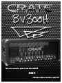
1
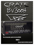
This is the operation guide for the Crate BV300H.
READ IT.
Then get ready for the Ride of your Life!
Contents:
A Message from the People Behind the BV300H
. . . . . . . . . .3
The Front Panel - Input & Channel 1 . . . . . . . . . . . . . .4
The Front Panel - Channel 2 . . . . . . . . . . . . . . . . . .5
The Front Panel - Channel 3 . . . . . . . . . . . . . . . . . .6
The Front Panel - Effects Loop, Eek & Ugh . . . . . . . . . . .7
The Rear Panel - Footswitch, Speaker Outputs, Slave Out
The Rear Panel - Effects Loop, Bias, AC Power
. . . .8
. . . . . . . . .9
Important Information About Tubes and Tube Products
A Brief History Of The Tube . . . . . . . . . . . . . . . .10
Tube Types And Usage
. . . . . . . . . . . . . . . . . . .10
The Nature Of Tubes: Why (And When) To Replace Them
. . . .11
The Importance Of Proper Biasing . . . . . . . . . . . . . .1
Survival Tips For Tube Amplifiers
Some Suggested Settings
The Block Diagram
. . . . . . . . . . . . .12
. . . . . . . . . . . . . . . . . . .13
. . . . . . . . . . . . . . . . . . . . . .14
Technical Specifications . . . . . . . . . . . . . . . . . . .15
CAUTION
PRECAUCION
ATTENTION
RISK OF ELECTRIC SHOCK
DO NOT OPEN
RIESGO DE CORRIENTAZO
NO ABRA
RISQUE D'ELECTROCUTION
NE PAS OUVRIR
WARNING: TO REDUCE THE RISK OF FIRE OR ELECTRIC SHOCK, DO NOT EXPOSE
THIS APPARATUS TO RAIN OR MOISTURE. TO REDUCE THE RISK OF ELECTRIC
SHOCK, DO NOT REMOVE COVER. NO USER-SERVICEABLE PARTS INSIDE. REFER
SERVICING TO QUALIFIED SERVICE PERSONNEL.
PRECAUCION: PARA REDUCIR EL RIESGO DE INCENDIOS O DESCARGAS ELECTRICAS, NO PERMITA QUE ESTE APARATO QUEDE EXPUESTO A LA LLUVIA O LA HUMEDAD. PARA DISMINUOIR EL
RIESGO DE CORRIENTAZO. NO ABRA LA CUBIERTA. NO HAY PIEZAS ADENTRO QUE EL USARIO
PUEDO REPARAR DEJE TODO MANTENIMIENTO A LOS TECHNICOS CALIFICADOS.
ATTENTION: PROTÉGEZ CET APPAREIL DE LA PLUIE ET DE L'HUMIDITÉ AFIN D'ÉVITER TOUT
RISQUE D'INCENDIE OU D'ÉLECTROCUTION. POUR REDUIRE D'ELECTROCUTION NE PAS ENLEVER
LE COUVERCLE. AUCUNE PIECE INTERNE N'EST REPRABLE PAR L'UTILISATEUR. POUR TOUTE
REPARATION, S'ADRESSER A UN TECHNICIEN QUALIFIE.
IMPORTANT SAFETY INSTRUCTIONS
• READ, FOLLOW, HEED, AND KEEP ALL INSTRUCTIONS AND WARNINGS.
• DO NOT OPERATE NEAR ANY HEAT SOURCE AND DO NOT BLOCK ANY VENTILATION OPENINGS ON THIS APPARATUS. FOR PROPER OPERATION, THIS UNIT REQUIRES 3”
(75CM) OF WELL VENTILATED SPACE AROUND HEATSINKS AND OTHER AIR FLOW PROVISIONS IN THE CABINET.
• DO NOT USE THIS APPARATUS NEAR SPLASHING, FALLING, SPRAYING, OR STANDING LIQUIDS.
• CLEAN ONLY WITH LINT-FREE DAMP CLOTH AND DO NOT USE CLEANING AGENTS.
• ONLY CONNECT POWER CORD TO A POLARIZED, SAFETY GROUNDED OUTLET WIRED TO CURRENT ELECTRICAL CODES AND COMPATIBLE WITH VOLTAGE, POWER, AND
FREQUENCY REQUIREMENTS STATED ON THE REAR PANEL OF THE APPARATUS.
•
•
•
•
•
•
PROTECT THE POWER CORD FROM DAMAGE DUE TO BEING WALKED ON, PINCHED, OR STRAINED.
UNPLUG THE APPARATUS DURING LIGHTNING STORMS OR WHEN UNUSED FOR LONG PERIODS OF TIME.
ONLY USE ATTACHMENTS, ACCESSORIES, STANDS, OR BRACKETS SPECIFIED BY THE MANUFACTURER FOR SAFE OPERATION AND TO AVOID INJURY.
WARNING: TO REDUCE THE RISK OF ELECTRIC SHOCK OR FIRE, DO NOT EXPOSE THIS UNIT TO RAIN OR MOISTURE.
SERVICE MUST BE PERFORMED BY QUALIFIED PERSONNEL.
OUR AMPLIFIERS ARE CAPABLE OF PRODUCING HIGH SOUND PRESSURE LEVELS. CONTINUED EXPOSURE TO HIGH SOUND PRESSURE LEVELS CAN CAUSE PERMANENT HEARING IMPAIRMENT OR LOSS. USER CAUTION IS ADVISED AND EAR PROTECTION IS RECOMMENDED IF UNIT IS OPERATED AT HIGH VOLUME.
EXPLANATION OF GRAPHICAL SYMBOLS:
EXPLICACION DE SIMBOLOS GRAFICOS:
EXPLICATION DES SYMBÔLES GRAPHIQUES:
"DANGEROUS VOLTAGE"
=
“VOLTAJE PELIGROSO”
"DANGER HAUTE TENSION"
"IT IS NECESSARY FOR THE USER TO REFER TO THE INSTRUCTION MANUAL"
=
“ES NECESARIO QUE EL USUARIO SE REFIERA AL MANUAL DE INSTRUCCIONES.”
"REFERREZ-VOUS AU MANUAL D'UTILISATION"
2
A Message from the People Behind the BV300H:
You now own the finest lead guitar amplifier in the world. The Crate BV300H was designed to
fulfill the needs of the professional musician. It is equally at home in the studio, in the
club, or on the big stage. This amplifier has been designed with key features to finely
sculpt its sound into YOUR sound. The BV300H uses premium materials and workmanship and is
made entirely in the U.S.A. It includes a full 5 year warranty on parts and labor and a 90
day warranty on tubes. Unlike some other amplifiers which only sound good when turned up,
the BV300H delivers the same awesome tone at low volumes that it does at high stage levels.
This is due to our unique power amplifier that produces the same sweet, warm juicy tone at
ANY level. 3 watts or 300 watts, the tone is consistent, strong and powerful.
Don’t let the 300W rating scare you. All amplifiers can benefit from added headroom. 300
watts allows the player to hear the detail and dynamics of the sound much better. The sound
is like nothing you have ever heard before. Imagine palm muting the low strings and actually
hearing the full dynamic. Many players don’t even know what this sounds like because their
amplifiers are underpowered. Have you ever started to turn your amplifier up louder only to
have the tone change, get flubby, fart out…. Lack of headroom. The only way to describe it
is to experience it.
Coupled with its massive power amplifier is a state of the art 3 channel preamp. Switching is
accomplished via momentary switches that provide instant access to each of the 3 channels.
A classic design originally used for bass or guitar, Channel 1 is full of dynamic headroom
and tonal versatility. It utilizes a clean, punchy preamplifier section with classic high
and low tone EQs and a 5-position midrange selector to further dial in your tone.
Channel 2 has a classic british tonality that will be familiar to most players. The warmth
and crunch of a naturally overdriven power amp is captured powerfully by this channel. Touch
sensitivity and dynamics are emphasized in this traditionally voiced preamp. This channel
provides creamy-smooth overdrive, with a slight compression effect.
Channel 3 is the power driver. It delivers the goods in a forceful, aggressive manner with
the slightest amount of tube compression. Voiced quite a bit harder than Channel 2, Channel
3 is like a sledgehammer pounding away.
Rounding out the front panel controls are a pair of power amp feedback controls, Eek and
Ugh. Use them for tuning the amplifier to different cabinets or rooms.
The rear panel consists of an array of speaker outputs, 1/4" and Neutrik Speakon®, slave
output with level control, bias controls and test points, and the effects loop with level
controls - switchable for series or parallel operation. The loop can be engaged from the
front panel switch or the supplied BVFS4 footswitch.
Speakon® is a registered trademark of Neutrik U.S.A.
3
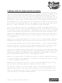
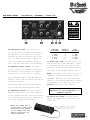
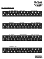
THE FRONT PANEL - Input, Channel 1:
1.Input Jack: 1 Meg Ohm input impedance 1/4”
input jack – plug your guitar in here.
2.Channel 1 Select Switch: When you want to
use Channel 1, press this switch. The green LED
above this switch lights up when Channel 1 is
selected. The BV300H uses instant access switching – when the footswitch (#28, rear panel) is
connected, either the front panel channel select
switches or the footswitch will select the
desired channel.
3.Gain: Use this control to adjust the input
gain for Channel 1. Towards the “–” side gives
you tight, dynamic clean tones. Towards the “+”
side you’ll get more crunch. Using a circuit
that was originally used for the bass or guitar, the gain is mild, yet thick & punchy. (A
humbucker will push the preamp intensely into
compression.)
provides a range of 38dB at 5kHz.
5.Mid Freq Select: Use this control to select
the frequency where the Mid control takes
effect – 300Hz, 700Hz, 1kHz, 1.5kHz, or 3kHz.
6.Mid: Use this control to adjust the midrange
level for Channel 1. The Mid control gives you
10dB of boost or 22dB of cut at whatever frequency the Mid Freq control (#6) is set to. The
Mid control is a peak/dip style filter.
7.Level: Use this control to adjust the output
level of Channel 1. Along with the Gain control
(#3), you can get the right blend of dynamics
for your playing style.
8.Bass: Use this control to adjust the low end
level for Channel 1. The Bass control provides
24dB of boost or cut at 50Hz.
4.Treble: Use this control to adjust the top
end level for Channel 1. The Treble control
4
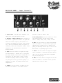
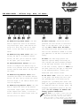
THE FRONT PANEL - Channel 2:
9.Channel 2 Select Switch: When you want to
use Channel 2, press this switch. The amber LED
above this switch lights up when Channel 2 is
selected. The BV300H uses instant access switching – when the footswitch (#28, rear panel) is
connected, either the front panel channel select
switches or the footswitch will select the
desired channel.
10.Gain: Use this control to adjust the input
gain for Channel 2. Towards the “–” side gives
you the classically British warm crunch. Towards
the “+” side gives you creamy smooth overdrive
with a touch of compression.
11.Treble: Use this control to adjust the top
end level for Channel 2. The Treble control
provides 12dB of boost or cut at 2kHz.
12.Mid Boost Select: Use this control to add
a 4~5dB boost from the low end up to the
midrange frequency selected: 250Hz, 500Hz,
750Hz, or 1kHz. There is, of course, no boost
when this control is at the “off” position.
13.Mid: Use this control to adjust the
midrange output level for Channel 2. The Mid
control gives you 10dB of boost or cut at
750Hz.
NOTE: The Mid Boost Select (#12) uses a different circuit than the Mid control (#13).
14.Level: Use this control to adjust the output level of Channel 2. Use this control along
with the Gain control (#10) to get the sound
you’re looking for on Channel 2.
15.Bass: Use this control to adjust the low
end level for Channel 2. The Bass control provides 20dB of boost or cut at 50Hz.
5
THE FRONT PANEL - Channel 3:
16.Channel 3 Select Switch: When you want
to use Channel 3, press this switch. The red
LED above this switch lights up when Channel 3
is selected. The BV300H uses instant access
switching – when the footswitch (#28, rear
panel) is connected, either the front panel
channel select switches or the footswitch will
select the desired channel.
17.Gain: Use this control to adjust the input
gain for Channel 3. Towards the “–” side gives
you a punchy tube sound perfect for aggressive
rhythm playing. Towards the “+” side and you’re
asking for some seriously aggressive tones!
18.Treble: Use this control to adjust the top
end level for Channel 2. The Treble control
provides 25dB of boost or cut at whatever frequency the High Freq control (#19) is set to.
19.High Freq Select: Use this control to
choose the frequency where the High control
takes effect – 10kHz, 8kHz, 6kHz, 4kHz or 2kHz.
20.Mid: Use this control to adjust the
midrange level for Channel 3. The Mid control
provides 20dB of boost or cut at 1.2kHz.
21.Level: Use this control to adjust the output level of Channel 3. Use this control along
the Gain control (#17) to get the sound you’re
looking for on Channel 3.
22.Bass: Use this control to adjust the low
end level for Channel 3. The Bass control provides 18dB of boost or cut at 100Hz.
6
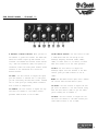
THE FRONT PANEL - Effects Loop, Eek & Ugh:
23.Loop Switch: When you want to engage the
rear panel effects loop, press this switch. The
blue LED above this switch lights up when the
effects loop is active. This can be used as a
“boost” feature – see the “Hot Tip” on page
9. The BV300H uses instant access switching –
when the footswitch (#28, rear panel) is connected, either the front panel loop switch or
the footswitch will activate the effects loop.
24.Eek!: This is your high frequency
power amp damping control. This is used to
add definition and edge to your sound. The
Eek! control helps to compensate for dark
rooms and/or speaker cabinets.
26.Standby Switch: Use this switch to
put the amplifier into “Stand By” mode the tube filaments are still turned on, but
the high voltage is deactivated.
NOTE: The Power switch must be turned on
for at least ONE MINUTE before you turn
on the Standby switch (#26).
27.Power Switch: Use this switch to turn
the amplifier on and off.
25.Ugh!: This is your low frequency power
amp damping control. This is used to control and shape the low end. Towards the “–”
side tightens up the bass and controls the
speaker cones better. Towards the “+” side
makes it more “thumpy” and allows the speaker
cones to move easier.
7
THE REAR PANEL - Footswitch, Speakers, Slave Out:
BIG WARNING:
IT MAY BE TEMPTING,
BUT NEVER PLUG
YOUR HEADPHONES
INTO THE SPEAKER
OUTPUT JACKS OF A
300 WATT AMPLIFIER!
28.Footswitch Jack: Use this jack to
connect the BVFS4 four-button footswitch to
the amplifier. This allows you to switch
channels and turn the effects loop on and
off - by remote foot control. Connect one
end of the supplied footswitch cable* to
this jack, the other end to the footswitch.
29.Speaker Output Jacks: Use these
jacks to connect your speaker cabinet(s) to
the amplifier. The wiring for the Speakon®
jacks is Pin 1+ = hot, Pin 1– = ground.
All six Speaker Output jacks are wired in
parallel, which lets you connect the amp to
a bunch of cabinets.
The minimum gauge of the wiring used for
these connecting cables should be 16GA!
30.Impedance Switch: Use this switch to
match the amplifier to the total impedance
of your speaker cabinets. Use the following
chart and make sure that this switch is at
the proper setting before playing!
*NOTE: You MUST use a
5-wire MIDI cable when
connecting the BVFS4
to the amplifier for
proper operation of
the footswitch.
IMPEDANCE
O F CABINETS
16 ohms
16 ohms
8 ohms
8 ohms
4 ohms
NUMBER OF
CABINETS
8
4
4
2
2
TOTAL
IMPEDANCE
2 ohms
4 ohms
2 ohms
4 ohms
2 ohms
31.Slave Out Jack: Use this jack to connect the amp to a slave amplifier, PA amp,
or recording console. The signal at the
Slave Out jack is an attenuated version of
the signal at the Speaker Output jacks.
NOTE: The
capable of
equipment.
control is
signal at the Slave Out jack is
potentially damaging certain
Make sure the Slave Out Level
all the way down before connect-
ing anything to the Slave Out jack. Then
slowly increase the Level control!
Never use the Slave Out if the
amplifier is not connected to a
speaker cabinet!
32.Slave Out Level: Use this knob to
adjust the output level of the Slave Out
signal (#31).
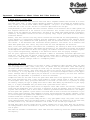
The BVFS4 footswitch - select channels
& turn the effects loop on and off
with just a tap of your foot!
8
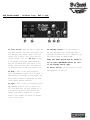
THE REAR PANEL - Effects Loop, Bias, AC Power:
33.Effects Loop Send Level: Use this
knob to adjust the level of the Effects
Loop Send signal (#34). Some effects are
picky as to what they like for an input
level, so use this knob to get them to
smile.
34.Effects Loop Send Jack*: When connecting the amp to an external effects
device, use this jack to send the signal
to the Input jack of the effect.
35.Series/Parallel Switch: Use this
switch to configure the effects loop in
series or in parallel with the signal path.
Certain effects sound better one way than
the other.
36.Effects Loop Return Jack*: When
connecting the amp to an external effects
device, use this jack to return the signal
from the output of the effects device back
into the amplifier.
37.Effects Loop Return Level: Use this
knob to adjust the level of the Effects
Loop Return signal (#36). Some effects have
hotter outputs than others, so use this
knob to adjust the return signal level for
the best level of effect.
38.Bias Controls: Authorized Service
personnel use this section to work their
magic on the amplifier. Like it says on
the amp: Don’t mess with the Bias!
Your Authorized Crate Service Center will
have all the information needed to re-bias
your amplifier if and when it becomes necessary.
39.Fuse: The fuse helps protect the
amplifier against damage from faulty AC
line voltages and other possible problems.
If the amp stops working, check the fuse.
If the fuse is blown, replace it ONLY with
the exact same size and type as indicated!
If the problem persists, contact your
Authorized Crate Service Center.
40.AC Inlet Jack: Insert the female end
of the power cord firmly into this jack.
The grounded power cord should only be
plugged into a grounded power outlet that
meets all applicable electrical codes and
is compatible with the voltage, power, and
frequency requirements stated on the rear
panel. Do not attempt to defeat the
safety ground connection!
* H O T T I P ! If you connect a signal cable from
the Effects Loop Send jack (#34) to the Effects
Loop Return jack (#36), the loop level control
adjust the amount of boost engaged - up to 6dB in
the series mode, up to 9dB in the parallel mode!
9
Important Information About Tubes And Tube Products:
A Brief History Of The Tube:
In 1883, Edison discovered that electrons would flow from a suspended filament when enclosed in an evacuated lamp. Years later, in 1905, Fleming expanded on Edison's discovery and created the "Fleming Valve".
Then, in 1907, Dr. Lee de Forest added a third component – the grid – to the "Fleming's Valve" and the
vacuum tube was a fact of life. The door to electronic amplification was now open.
During World War II, data gleaned from their intensive research on the detectors used in radar systems led
Bell Telephone Laboratories to the invention of the transistor. This reliable little device gained quick
support as the new component for amplification. The death of the vacuum tube seemed imminent as designers,
scientists, and engineers reveled in the idea of replacing large, fragile glass tubes with these small,
solid-state devices.
However, there were (and still are) many serious listeners who realized that the sound produced by a "transistor" amplifier is significantly different from that produced by a tube amplifier with identical design
specifications. They considered the sound produced by these new solid-state devices to be hard, brittle,
and lifeless. It was determined that solid-state devices produced a less musical set of harmonics than
tubes. When pushed past their limits, they tend to mute the tone and emphasize the distortion.
Tubes, on the other hand, produce a more musical set of harmonics, the intensity of which can be controlled
by the player. This characteristic adds warmth and definition to the sound which has become the hallmark
of tube amplifiers. When tubes are driven into clipping, the harmonic overtones can be both sweet and pleasing or intense and penetrating, depending on the musician’s musical taste and playing technique.
Over the years, application engineers have designed a number of outstanding solid-state amplifiers that
sound very, very good. Some use special circuitry which enables them to simulate the distortion characteristics of a tube amplifier. However, the tube amplifier, still held in the highest esteem by many musicians, offers a classic "vintage" sound in a contemporary market.
Tube Types And Usage:
Tube amplifiers are based primarily on two types of tubes – preamplifier tubes and power tubes. The tubes
used in preamplifiers (12AX7, 12AU7, 12AT7, etc.) are smaller than the power tubes. These tubes amplify
the signal from your instrument and shape the sound. They are inherently microphonic (mechanically pick up
and transmit external noises). Since these tubes are used in the critical first stages of a tube amplifier's circuitry, it is very important to use high-quality, low noise/low microphonic tubes for this application. Although tubes of this quality may be difficult to find and typically cost more than "off-theshelf" tubes, the improvement in performance is worth the investment.
Preamplifier tubes are also used to drive the power tubes. When used in this application, a 12AX7 will produce a more distorted tone than a 12AT7, which produces a clearer, sweeter sound. A 12AU7 is even cleaner and brighter than a 12AT7, giving more definition to the sound. (In some cases it is possible to change
the sound by changing the type of preamp and/or driver tubes. When making any modification to your equipment, it is highly recommended that you consult with a qualified service center.)
The power tubes are the largest tubes used in an amplifier. These tubes convert the low-level, conditioned
signal from the preamplifier into a level that is sufficient to drive the speakers. There are several types
of power tubes available, each of which offers a different performance/sound characteristic. For example,
the EL34 power tube produces a great Classic rock sound. When an EL34 is driven into distortion it produces a unique sound ("crunch"). When compared to the 6L6, the EL34 distorts more quickly, exhibits a "looser" low-end response and produces more harmonics at mid and high frequencies ("creamier" sound). These differences become more noticeable at higher volumes.
The 6L6 tubes produce a big low-end thump and have a very good dynamic range. They offer a more traditional "American Rock" sound. The 6V6 tubes produce a creamy sound with nice distortion. On the other hand,
the KT88 produces a big low-end but sounds more like an EL34 in the mid and high frequencies.
The 6550 power tubes are more rugged and stay cleaner sounding even at full power. When they do distort,
the sound produced is more solid and has a tighter low end; more of a "heavy metal" type distortion with
lots of power.
Some tubes are available in matched sets. These tubes have been extensively tested for optimum performance
and longevity.
10
The Nature Of Tubes: Why (And When) To Replace Them:
Tubes are made up of a number of fragile mechanical components that are vacuum-sealed in a glass envelope
or bubble. The tube's longevity is based on a number of factors which include how hard and often the amplifier is played, vibration from the speakers, road travel, repeated set up and tear down, etc.
Any time you notice a change in your amplifier's performance, check the tubes first.
If it's been a while since the tubes were replaced and the sound from your amplifier lacks punch, fades
in and out, loses highs or lows or produces unusual sounds, the power tubes probably need to be replaced.
If your amplifier squeals, makes noise, loses gain, starts to hum, lacks "sensitivity", or feels as if it
is working against you, the preamplifier tubes may need to be replaced.
The power tubes are subjected to considerably more stress than the preamplifier tubes. Consequently, they
almost always fail/degrade first. If deteriorating power tubes aren't replaced they will ultimately fail.
Depending on the failure mode, they may even cause severe damage to the audio output transformer and/or
other components in the amplifier. Replacing the tubes before they fail completely has the potential to
save you time, money and unwanted trouble. Since power tubes work together in an amplifier, it is crucial
that they (if there is more than one) be replaced by a matched set. If you're on the road a lot, we recommend that you carry a spare matched set of replacement power tubes and their associated driver tubes.
After turning off the power and disconnecting the amplifier from the power source, carefully check the
tubes (in bright light) for cracks or white spots inside the glass or any other apparent damage. Then, with
the power on, view the tubes in a dark room. Look for preamplifier tubes that do not glow at all or power
tubes that glow excessively red.
Whenever you replace the power tube(s):
• Always have the amplifier's bias voltage checked by a qualified service center. Improper bias voltage
will cause degradation in performance and possibly damage the tubes and/or the amplifier. (See the section
below entitled, "The Importance of Proper Biasing", for more information on this subject).
• We highly recommend that you replace the driver tube(s) as well. The driver tube determines the shape
and amplitude of the signal applied to the power tube(s) and has to work almost as hard as the power
tube(s).
You can check your preamplifier tubes for microphonics by turning the amplifier on, turning up the gain
and tapping lightly on each tube with the end of a pencil or a chop stick (my favorite). You will be able
to hear the tapping through your speakers, which is normal. It is not normal for a tube to ring like a
bell after it’s tapped. If it does ring then it’s microphonic and should be replaced. Remember to use only
high quality, low microphonic tubes in the preamplifier section.
Even though power tubes are rarely microphonic, you should check them anyway. The power tubes can be checked
for microphonics just like pre-amp tubes.
In the case of very high gain amps, you may be able to reduce the amount of noise generated by simply swapping the preamp tubes around.
The Importance Of Proper Biasing:
For the best performance and longest tube life, proper biasing is imperative. Bias is the negative voltage which is applied to the power tube’s control grid to set the level of idle current. We cannot over
emphasize the difference in warmth of tone and dynamic response that come with proper biasing. If the bias
is set too high (overbiased), the sound from the amp will be distorted at all levels. If the bias is set
too low, (under biased) the power tubes will run hot (the plates inside the tubes may glow red due to
excessive heat) and the sound from the amplifier will lack power and punch. The excessive heat greatly
reduces tube life – from a few days to as little as a few hours in extreme cases. Setting the bias on your
amp is like setting the idle on your car. If it’s too high or hot it’s running away with you and if it’s
too low or cold it will choke when you step on it.
The bias is adjusted at the factory in accordance with the type of power tube(s) installed in your amplifier. It is important to point out that tubes of the same type and specification typically exhibit different performance characteristics. Consequently, whenever power tubes are replaced, the bias voltage must
be checked (unless the amplifier is equipped with "self-biasing circuitry) and readjusted to accommodate
the operating parameters of the replacement tubes.
Depending on the model and amplifier type, there may be hum balance controls, trim pots, or bias adjustment controls on its rear panel. However, the bias adjustment should be performed only by qualified service personnel with the proper, calibrated test equipment.
11
Survival Tips For Tube Amplifiers:
To prolong tube life, observe these tips and recommendations:
• Match the impedance of your speaker cabinet(s) to your amplifier. Improper impedance matching will contribute to early tube degradation and may cause premature tube failure.
• Make sure the speaker(s) are properly connected prior to turning on the amplifier.
• After playing the amplifier, allow sufficient time for it to properly cool down prior to moving it. A
properly cooled amplifier prolongs tube life due to the internal components being less susceptible to
the damage caused by vibration.
• Allow the amplifier to warm up to room temperature before turning it on. The heat generated by the tube
elements can crack a cold glass housing.
• Replace the output tube(s) before the performance degrades or the tubes fail completely. Replace the
tube(s) on a regular basis (at least once per year or as often as every 4 to 6 months if you play long
and hard every day).
• Always have the bias checked after replacing the output tubes (unless the amplifier is equipped with
"self-biasing circuitry"). This should be done ONLY at a qualified service center. Improper biasing could
result in the tubes running too hot, which greatly reduces the life of the tubes – or too cold, which
results in distorted sound regardless of level settings. Do not play the amplifier if it exhibits these
symptoms – get the bias checked/adjusted immediately to prevent tube failure and/or other damage.
• If the locating notch on the base of a power tube breaks off, replace the tube. This significantly
reduces the risk of damaging your amplifier by incorrectly inserting the tube.
• Protect the amplifier from dust and moisture. If liquid gets into the amplifier proper, or if the amplifier is dropped or otherwise mechanically abused, have it checked out at an authorized service center
before using it.
• Proper maintenance and cleaning in combination with routine checkups by your authorized service center
will insure the best performance and longest life from your amplifier.
CAUTION: Tube replacement should be performed only by qualified service personnel who are
familiar with the dangers of hazardous voltages that are typically present in tube circuitry.
12
Some Suggested Settings:
Chug Rhythm (Humbucker):
Bluesy Stang:
Sparkling Clean:
Metal Sound:
Rock Sound:
Spitty Gain (Humbucker):
Evil Thoughts:
Chunk (Humbucker):
Bluesy Tone (Strat):
As Sick As It Gets:
13
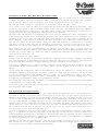
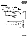
The Block Diagram:
V1
V1
V2
V2
GAIN
LEVEL
BASS TREBLE
INPUT
V1–V8 = 12AX7
V9–V10 = 12AU7
V11–V16 = 6550A
MID
300
3k
1.5k 1k 700
V3
V6
V6
V7
GAIN
LEVEL
SEND
RETURN
BASS MID TREBLE
OFF
1k
750 500 250
V4
V4
V5
EFFECTS
LOOP
V5
GAIN
LEVEL
BASS MID TREBLE
10k
2k
4k 6k 8k
1+
1-
V9
V10
V11
V13
V15
1+
IMPEDANCE
SELECTOR
V8
V9
EEK!
V10
V12
V14
SPEAKON
SPEAKER
OUTPUTS
V16
1-
1/4"
SPEAKER
OUTPUTS
UGH!
LEVEL
SLAVE
OUT
14
Technical Specifications:
OUTPUT POWER RATING
300 Watts RMS @ 5% THD, 4 ohm load, 120 VAC
SIGNAL TO NOISE RATIO
75dB Typical
GAIN
Channel 1
Channel 2
Channel 3
80dB
105dB
105dB
Channel 1
Channel 2
Channel 3
LOW
24dB range @ 50Hz
20dB range @ 50Hz
18dB range @ 100Hz
MID
+10/-22dB @ EQ Switch
10dB range @ 750Hz
20dB range @ 1.2kHz
EQ SWITCH
300,700,1k,1.5k or 3kHz
+4~5dB @ 250,500,750 or 1KHz
2k, 4k, 6k, 8k or 10kHz
HIGH
38dB range @ 5kHz
12dB range @ 2kHz
25dB range @ EQ Switch
EQs
EEK!
6dB @ 5kHz
UGH!
5dB below 250Hz
PREAMP TUBES
(8) 12AX7A, (2) 12AU7
POWER TUBES
(6) 6550A
POWER REQUIREMENTS
120 VAC, 60 Hz, 600VA
100/115 VAC, 50/60 Hz, 600VA
230 VAC, 50/60 Hz, 600VA
SIZE A N D WEIGHT
30”W x 12-1/2” H x 11”D, 80 lbs.
Specifications and information subject to change without notice.
The BV300H is covered with heavy duty Tolex® - wipe it clean from time to time with a soft damp cloth.
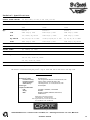
Declaration Of Conformity
#35, Effective 01-01-2001
Manufacturer’s Name:
Production Facility:
Production Facility:
Shipping Facility:
Office Facility:
SLM Electronics
1901 Congressional Drive, St. Louis, MO 63146, USA
700 Hwy 202 W, Yellville, AR 72687, USA
1400 Ferguson Ave., St. Louis, MO 63133, USA
1400 Ferguson Ave., St. Louis, MO 63133, USA
Product Type:
Audio Amplifier
Complies with Standards:
LVD:
Safety:
EMC:
92/31/EEC, 93/68/EEC, & 73/23/EWG
EN60065
EN55013, EN55020, EN55022, EN61000-3-2,
& EN61000-3-3
Supplementary information provided by:
SLM Electronics - R & D Engineering
1901 Congressional Drive, St Louis, MO 63146, USA
Tel.: 314-569-0141, Fax: 314-569-0175
www.crateamps.com
©2002 SLM Electronics • A division of St. Louis Music, Inc. • 1400 Ferguson Avenue • St. Louis, MO 63133
47-329-02 • 05/13/03
15