1
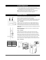
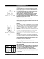
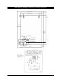
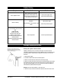
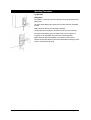
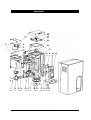
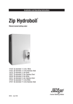
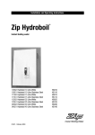
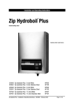
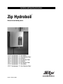
Installation and Operating Instructions
®
Zip Hydroboil
Filtered instant boiling water
01512
01511
03512
03511
05512
05511
07512
07511
Zip Hydroboil
Zip Hydroboil
Zip Hydroboil
Zip Hydroboil
Zip Hydroboil
Zip Hydroboil
Zip Hydroboil
Zip Hydroboil
81446 - February 2005
1.5 Litre White
1.5 Litre Stainless Steel
3 Litre White
3 Litre Stainless Steel
5 Litre White
5 Litre Stainless Steel
7.5 Litre White
7.5 Litre Stainless Steel
Page 2 of 12
Zip Hydroboil - Installation & Operating Instructions - 81446 - February 2005
Contents
Read These Warnings First . . . . . . . . . . . . . .4
Installation Requirements . . . . . . . . . . . . . . .4
Installation Procedures . . . . . . . . . . . . . . . . .5
Step 1 – Positioning . . . . . . . .5
Step 2 – Fastening . . . . . . . . .5
Step 3 – Connecting . . . . . . .6
a) Plumbing . . . . . . . .6
b) Venting . . . . . . . . .6
c ) Electrical . . . . . . .6
Step 4 – Assembling . . . . . . .6
Step 5 – Commissioning . . . .6
Wall Mounting Template Dimensions
& Electrical Diagram . . . . . . . . . . . . . . . . . . .7
Problem Solving . . . . . . . . . . . . . . . . . . . . . .8
Earthing Continuity Verification . . . . . . . . . . .8
Operating Procedures . . . . . . . . . . . . . . . . . .9
Spare Parts . . . . . . . . . . . . . . . . . . . . . . . . . .10
Contact Details . . . . . . . . . . . . . . . . . . . . . . .12
Note:
Read all instructions and precautions before proceeding. This unit must be
installed in accordance with water supply by-laws, current IEC regulations and
relevant local authority by-laws.
Zip Hydroboil - Installation & Operating Instructions - 81446 - February 2005
Page 3 of 12
Read These Warnings First
Please read all installation requirements, installation procedures and
precautions before installing any Zip Hydroboil instant boiling water heater.
Never attempt to install any Zip Hydroboil instant boiling water heater without
reading all of the applicable instructions.
In some hard water areas where mineral scale accumulation in the boiling
chamber of the Zip Hydroboil may become a problem, consideration should be
given to the maintenance required. A suitable form of water treatment may be
necessary.
All plumbing connections must be made in accordance with local regulations.
The Zip Hydroboil instant boiling water heater is not intended for use by young
children or infirm people without supervision.
Young children should be prevented from having access to ensure that they are
not able to use or play with the heater.
If the installation site is located more than 1000 metres above sea level, the
installer should contact a Zip authorised agent for high altitude settings.
This appliance must be earthed. If the power supply cord is damaged it must
be replaced by a Zip authorised agent or a qualified electrician.
Do not remove the cover of the heater under any circumstances without first
isolating the heater from the power supply.
Do not use strong, corrosive or abrasive cleaners to clean the case of the
heater.
Frost protection: If this heater is located where ambient air temperature could
fall below 5ºC when the heater is not in use, do not turn off the appliance
electrically. This safeguard does not offer the same protection to the connecting
pipework and fittings.
The ambient temperatures this unit should operate within are 5ºC - 50ºC.
This heater is intended only for indoor use and should never be installed
outdoors or be exposed to the elements of nature.
This unit must not be positioned in an area that may be cleaned by a water jet.
This unit must not be cleaned by a water jet.
Installation Requirements
Before installing, ensure that the following are available:
a) Sufficient space to position the heater so there is at least 150 mm
clearance above the heater for service access, 65 mm to its left and
20 mm to its right – the tap outlet usually should be positioned at least
200 mm above a draining board or drip tray.
b) Power supply connection to the heater via a double pole fused spur with a
minimum break rating that adequately covers the maximum power usage.
For units with 3.6 Kw element (25 ltr) or multi element units (40 ltr) an
isolating switch in the fixed wiring and attached to a secure surface is
required. This switch must provide all-pole disconnection and a contact
seperation of at least 3 mm installed in accordance with wiring rules.
c) Cold water supply with a minimum working pressure of 1 bar and a
maximum working pressure of 7 bar connected via an isolation valve.
d) Outlet drainage to a sink draining board or to a drip tray.
Page 4 of 12
Zip Hydroboil - Installation & Operating Instructions - 81446 - February 2005
Installation Requirements
e) Access to drainage from a vent situated at the base of the heater.
f) In all installation instances the walls of the heater must be vertical and the
base horizontal, there can be no exceptions to this rule.
Note: If the water pressure is likely to exceed 7 bar, a 3.5 bar pressure
reducing valve must be installed in the cold water supply line.
Installation Procedures
Before You Begin
Locate the paper mounting-hole template packed with the heater.
VENT
OUTLET
COLD
INLET
Read the installation and operating instructions completely.
Decide whether to install with concealed or exposed plumbing and/or electrical
connections. Concealed connections are preferred for superior appearance.
Step 1 – Positioning
INLET
POSITION
Position the heater so the tap will drain on to a draining board or drip tray.
VENT
POSITION
Position the base of the tap to be not less than 200 mm above the draining
board (height should be increased only if essential for filling larger vessels).
Provide clearance for service access of not less than 150 mm top, 65 mm left,
20 mm right.
Mark corner positions for the heater on the wall so as to position the paper
mounting-hole template.
Step 2 – Fastening
45mm
Position mounting-hole template on wall and drill holes where shown.
Drill holes for water inlet, vent outlet and wiring if rear access is intended.
Remove cover fastening screws from heater and lift whole cover off heater.
Install plumbing and wiring and prepare pipe ends and wiring ends as shown.
Screw heater chassis to the wall using screws or bolts suited to the wall.
Elbow
Screws or bolts must be capable of supporting the heater weight when filled.
Step 3 – Connecting
Approximate Weight When Filled
1.5 Litre models
10 kg
3.0 Litre models
12.5 kg
5.0 Litre models
16.5 kg
7.5 Litre models
20.5 kg
Zip Hydroboil - Installation & Operating Instructions - 81446 - February 2005
Page 5 of 12
Installation Procedures Continued
a) Plumbing
For exposed plumbing connection, connect the cold water inlet pipe from the
base of the heater directly to the 15 mm or half-inch compression fittings with
the nuts and olives provided.
250mm
Wring
45 mm
For concealed plumbing connections, connect the cold water pipe through the
rear of the chassis using a 15 mm or half-inch capillary elbow.
Cold water pipes must be flushed before connection to the inlet. Any clogging
due to sediment or fines will adversely affect the operation of the heater.
Concealed
Vent
Concealed
Inlet
It is recommended that the heater be installed with a stop cock which allows it
to be isolated from the mains supply for servicing.
Water pressure requirements:
Minimum - 1 bar (100 kPa). Maximum - 7 bar (700 kpa).
Warning: If pressure is likely to exceed 7 bar (700 kpa), a pressure limiting valve
must be installed in the cold water supply line. Zip recommends a valve rated at
3.5 bar (350 kpa) for this application.
b) Venting
A vent at the base of the heater must be plumbed to a safe visible location as,
under certain conditions, it may discharge cold or boiling water and/or steam.
For exposed vent plumbing, connect vent outlet from the base of heater to a
15 mm or half inch OD pipe which has a continuous fall, is no more than 3
metres long, has no more than 3 right angle bends, and discharges to a waste
water drain.
For concealed vent plumbing, connect plumbing to the vent outlet from the
heater rear using a capillary elbow protruding 45 mm from the wall.
Vent line
Visible Tundish
Alternatively attach a tun dish to the wall as shown and plumb away to waste.
c) Electrical
For concealed electrical connection, connect a power cable through the rear
access opening of the heater to the terminal block within the heater as shown.
For exposed electrical connection, connect the flex and plug (fitted to the
heater) to a standard power outlet on the wall within 1500 mm of the heater
that will adequatly cater for the units power needs.
Do not turn the power ON until the heater is filled with water.
Step 4 – Assembling
Place the heater case back on to the heater and secure the top 2 case screws.
Secure two bottom case screws.
Step 5 – Commissioning
1.5 Litre models
10 min 11 min
Check previous steps. Turn water supply ON. Water is now flowing into heater,
check connections for leaks. Wait approximately 5 minutes and check outlet
tap for water. This is acheived by pulling the tap handle forward.
3.0 Litre models
16 min 17 min
Power is only to be turned on when water is available from this outlet.
5.0 Litre models
16 min 17 min
7.5 Litre models
23 min 24 min
Inlet water
temperature
Page 6 of 12
15°C
10°C
Turn power ON. After a short period, boiling water will be available and will be
maintained close to boiling point thereafter. Initial heating periods are shown in
the table on the left.
Zip Hydroboil - Installation & Operating Instructions - 81446 - February 2005
Wall Mounting Template Dimensions & Electrical Diagram
274 (1.5 L & 3.O L)
38 (1.5 L & 3.O L)
304 (5.0 L & 7.5 L)
53 (5.0 L & 7.5 L)
19
150
CLEAR
65 CLEAR
318 5.O L
416 3.O L
448 5.O L
561 7.5 L
56
POSITIONING PIN
COLD
INLET
VENT
EXTERNAL PLUMBING
ELECTRICAL WIRING
POSITION
72
INTERNAL PLUMBING
15
25
35
20
42
BENCH TOP
Zip Hydroboil - Installation & Operating Instructions - 81446 - February 2005
Page 7 of 12
Problem Solving
Sympton
Possible Cause
Solution
Fails to dispense water.
Water isolating valve turned off.
Blocked filter, blocked meter tube,
blocked strainer, jammed ball valve
assy, airlock in transfer tube.
Check water supply valve.
Contact Zip authorised agent.
No power.
Water not boiling.
Runs out of boiling water and fails to
refill.
Outlet tap drips.
Overflow from vent.
Excessive steam from vent.
Power “on” but no heat.
Overload repeatedly tripping with
excessive steam.
Overload repeatedly tripping without
excessive steam.
Check power supply.
Faulty thermostat, faulty element, faulty
cutout.
Contact Zip authorised agent.
Internal adjustment.
Contact Zip athorised agent.
Earthing Continuity Verification
If required, an earth continuity test can be
performed by testing between the earth pin on
the products lead and a exposed piece of metal
on the case and the tap body.
Warning: this appliance must be earthed.
Following remedial service the earthing continuity of the heater must be
checked by a qualified technician using an appliance tester, or continuity tester
of accuracy Class 5 or better. Class 5 denotes an accuracy of 5% full scale
deflection.
1. Isolate power supply.
2. Set meter to 0 ohm with leads connected together.
3. Connect one test lead to the earth pin on the three pin plug.
4. Connect the other test lead to a bare patch of metal (preferably on the edge)
of the top of the cover, then to the front cover of the unit, and then to the tap
top under the plastic paddle. This can be achieved by inserting the probe up
from behind the paddle without losing water.
Warning- the water may be boiling - show extra care.
5. Test that in every instance the electrical resistance does not exceed 1 ohm.
Page 8 of 12
Zip Hydroboil - Installation & Operating Instructions - 81446 - February 2005
Operating Procedures
Tap Operation
Boiling water
Zip Hydroboil is fitted with a two-way cool-touch safety tap for filtered instant
boiling water.
For filtered instant boiling water, gently press the lower end of the tap paddle
inwards.
Boiling water will flow until the tap paddle is released.
This operation gives fingertip flow control for safe filling of cups and mugs.
For filtered instant boiling water to fill larger vessels such as teapots and
saucepans, lift the tap paddle until it locks into a horizontal position.
Boiling water will flow until the paddle is returned to its normal vertical
position. This operation allows the vessel to be filled without holding your hand
where it may be affected by steam.
Zip Hydroboil - Installation & Operating Instructions - 81446 - February 2005
Page 9 of 12
Spare Parts
Page 10 of 12
Key
Part No
Description
1
90487
Cistern Lid Clamp kit 2000B
2
90488
Cistern Lid and Gasket kit 2000B
3
90490
Gasket kit Hydroboil 2000B
4
90083
Float valve kit w/ float 2000B
5
90069
Jumper valve kit w/ seals 2000B
6
90102
Cistern float kit w/ nut and screw
7
90493
Metering tube kit 1500w 2000B
90494
Metering tube kit 2400w 2000B
8
90495
Banjo screw Hydroboil 2000B version 2
9
90496
O-Ring kit Hydroboil 2000B
10
90507
Fascia lens and actuator kit 2000B (coated)
11
90508
PCB kits Hydroboil 2000B
12
90081
Thermostat Kit
13
90127
Overload kit Hydroboil 2000B
14
90511
Tap Handle Hydroboil HB
15
90510
Outlet Nozzle Hydroboil 2000B
16
90503
Strap and key kit 1.5 & 3L 2000B
90504
Strap and key kit 5 & 7.5L 2000B
17
90505
Tap nut kit Hydroboil 2000B
18
90509
Tap body kit Hydroboil 2000B
19
90485
Element kit 1500W / 240V 2000B
90486
Element kit 2400W / 240V 2000B
20
90491
Cleaning hole cover kit
21
90492
Drain cap & seal kit
22
------
------------------------
23
90107
Filter kit Cold Inlet Bush
24
90131
Lid, Gasket & Clips Kit 1.5L & 3.0L
24
90132
Lid, Gasket & Clips Kit 5.0L & 7.5L
25
90141
Tank welded 1.5L Kit
25
90142
Tank welded 3.0L Kit
25
90143
Tank welded 5.0L Kit
25
90144
Tank welded 7.5L Kit
26
90146
Insulation Kit 1.5L
26
90147
Insulation Kit 3.0L
26
90148
Insulation Kit 5.0L
26
90149
Insulation Kit 7.5L
27
90130
Clips for Curled Tank Kit
Zip Hydroboil - Installation & Operating Instructions - 81446 - February 2005
Spare Parts
26
1
27
24
5
2
4
9
3
25
13
6
16 11 10 14
7
1
12
19 8
23 9 1
20 21
17 9 18 15
Zip Hydroboil - Installation & Operating Instructions - 81446 - February 2005
Page 11 of 12
Warranty Information
The Zip appliance you have chosen is precision-built from the finest materials
available and should give many years of trouble free service.
Certain warranties may be implied by law into your contract with Zip. The
warranty provided below is additional to these implied warranties and nothing
set out below shall limit your statutory rights or rights at law.
Zip Heaters (UK) Pty Ltd warrants that, should any part fail within 24 calendar
months of installation, that part will be repaired or replaced free of charge by
Zip or its Distributor or Service Provider, except as set out below, provided the
appliance is installed and used strictly in accordance with the instructions
supplied, and that failure is not due to accident, misuse, abuse, unsuitable
water conditions, or to any alteration, modification or repair by any party not
expressly nominated by Zip.
No costs are payable by the customer other than any mileage or travelling-time
charges incurred by a Zip Service Provider or the cost of removal, cartage and
re-installation of any component of the appliance if it needs to be returned for
repair to Zip or its Distributor.
This warranty does not cover damage resulting from non-operation of the
appliance or consequential damage to any other goods, furnishings or property.
No warranty applies to the life of any filtration cartridge installed with the
appliance as cartridge life may vary according to water quality and the rate of
water consumption.
Zip does not exclude, restrict or modify any liability that cannot be excluded,
restricted or modified or which cannot, except to a limited extent, be excluded,
restricted or modified as between the owner or user and Zip under the laws
applicable.
Furthermore, this warranty does not displace any statutory warranty, but, to the
extent to which Zip is entitled to do so, the liability of Zip under any statutory
warranty will be limited at Zip's option to the replacement of the appliance or
supply of equivalent appliance, the payment of the cost of replacing the
appliance or acquiring an equivalent appliance, or the payment of the cost of
having the appliance repaired or the repair of the appliance.
Registering Your Purchase
Head Office
Zip Heaters (UK) Pty. Ltd.
14/15 Bertie Ward Way
Rashe’s Green Dereham
NORFOLK NR19 1TE
Registering your Zip installation on the Zip website may help to establish date
of installation should it become necessary to service the appliance under terms
of the Zip warranty. To register your installation go to www.zipheaters.co.uk and
look under the heading "Warranty".
Website: www.zipheaters.co.uk
Telephone: 0870 608 8888
Facsimile: 01362 692 448
Zip Hydroboil - Installation & Operating Instructions - 81446 - February 2005
Page 12 of 12