1
D-Link ™ DES-3326SR
24-Port Layer 3 Stackable Switch
With Optional RPS Support
Manual
May 2005
651SR3326S035
D-Link DES-3326SR Layer 3 Switch
____________________
Information in this document is subject to change without notice.
© 2005 D-Link Corporation. All rights reserved.
Reproduction in any manner whatsoever without the written permission of D-Link
Corporation is strictly forbidden.
Trademarks used in this text: D-Link, the D-LINK logo are trademarks of D-Link Computer Corporation; Microsoft and Windows are
registered trademarks of Microsoft Corporation.
Other trademarks and trade names may be used in this document to refer to either the entities claiming the marks and names or their
products. D-Link Computer Corporation disclaims any proprietary interest in trademarks and trade names other than its own.
May 2005 P/N 651SR3326S035
ii
TABLE OF CONTENTS
About This Manual ........................................................................................................................................... vii
Intended Readers............................................................................................................................................... vii
Notes, Notices, and Cautions ............................................................................................................................ vii
Safety Instructions ............................................................................................................................................... viii
Introduction............................................................................................................................................................. 1
Switch Description.......................................................................................................................................... 1
Features ............................................................................................................................................................... 2
Front Panel Components ..................................................................................................................................... 3
LED Indicators................................................................................................................................................ 3
Stacking LED Indicators ................................................................................................................................. 4
Rear Panel Description........................................................................................................................................ 5
Side Panels ...................................................................................................................................................... 5
Optional Plug-in Modules ................................................................................................................................... 6
Management Options ........................................................................................................................................ 15
Installation............................................................................................................................................................. 16
Package Contents .......................................................................................................................................... 16
Before You Connect to the Network................................................................................................................. 17
Connecting the Console Port......................................................................................................................... 17
Password Protection.......................................................................................................................................... 18
IP Address Assignment..................................................................................................................................... 19
SNMP Settings.............................................................................................................................................. 20
Installing the Switch in a Rack...................................................................................................................... 22
Connecting Stacked Switch Groups.................................................................................................................. 23
Configuring a Switch Group for Stacking..................................................................................................... 25
Notes on Standalone Operation..................................................................................................................... 26
Connecting Devices to the Switch .................................................................................................................... 28
Installing a Redundant Power Supply ............................................................................................................... 29
Connect to RPS ............................................................................................................................................. 30
Basic Switch Management.................................................................................................................................... 31
Before You Start ........................................................................................................................................... 31
General Deployment Strategy ....................................................................................................................... 32
Web-based User Interface ............................................................................................................................. 33
Basic Setup........................................................................................................................................................ 35
Switch Information ....................................................................................................................................... 35
Switch IP Settings ............................................................................................................................................. 36
User Accounts Management ............................................................................................................................. 38
Admin and User Privileges ........................................................................................................................... 39
Saving Changes................................................................................................................................................. 39
Factory Reset .................................................................................................................................................... 40
Restart System............................................................................................................................................... 41
Stacking Mode ...................................................................................................................................................... 42
Port Configuration................................................................................................................................................. 44
Configure Ports ............................................................................................................................................. 45
Traffic Segmentation..................................................................................................................................... 49
Link Aggregation .................................................................................................................................................. 50
Configure Link Aggregation ......................................................................................................................... 51
Port Mirroring ....................................................................................................................................................... 54
MAC Forwarding.................................................................................................................................................. 55
MAC Address Aging Time ........................................................................................................................... 55
Unicast MAC Address Forwarding............................................................................................................... 55
Multicast MAC Address Forwarding............................................................................................................ 57
Broadcast/Multicast Storm Control............................................................................................................... 58
Spanning Tree Protocol......................................................................................................................................... 60
802.1w Rapid Spanning Tree........................................................................................................................ 60
Configure STP Switch Settings......................................................................................................................... 61
STP Port Settings .......................................................................................................................................... 63
Quality of Service Configuration .......................................................................................................................... 65
Configure QoS Output Scheduling ............................................................................................................... 66
Configure 802.1p User Priority..................................................................................................................... 67
Configure Default Priority ............................................................................................................................ 68
Configure Bandwidth Control....................................................................................................................... 69
MAC Notification ................................................................................................................................................. 70
System Log ........................................................................................................................................................... 72
SNTP Settings....................................................................................................................................................... 74
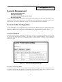
Security Management ........................................................................................................................................... 77
Access Profile Configuration ............................................................................................................................ 77
CPU Interface Filtering..................................................................................................................................... 84
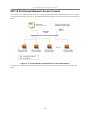
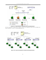
802.1X Port-based Network Access Control .................................................................................................... 90
802.1X Configuration ....................................................................................................................................... 92
Port Capability .............................................................................................................................................. 95
SNMP Network Management ............................................................................................................................... 99
SNMP Version .................................................................................................................................................. 99
SNMP View Table ...................................................................................................................................... 100
SNMP Group Table .................................................................................................................................... 101
SNMP Community Table............................................................................................................................ 102
SNMP Engine ID ........................................................................................................................................ 103
SNMP Host Table ....................................................................................................................................... 104
SNMP User Table ....................................................................................................................................... 105
Security IP Management ............................................................................................................................. 106
Network Monitoring and Statistics ..................................................................................................................... 107
Port Utilization Statistics............................................................................................................................. 108
Port Packet Statistics ................................................................................................................................... 109
MAC Address Table ................................................................................................................................... 112
Routing Table.............................................................................................................................................. 113
ARP Table................................................................................................................................................... 114
OSPF Information ....................................................................................................................................... 115
DVMRP Information .................................................................................................................................. 117
PIM Neighbor Address Table ..................................................................................................................... 119
GVRP Status ............................................................................................................................................... 119
Router Ports ................................................................................................................................................ 120
IGMP Snooping Group Table ..................................................................................................................... 121
IGMP Snooping Forwarding Table............................................................................................................. 121
IGMP Group Table ..................................................................................................................................... 122
IP Multicast Forwarding Table ................................................................................................................... 123
802.1X Authentication Status ..................................................................................................................... 123
Switch History............................................................................................................................................. 124
Switch Utilities.................................................................................................................................................... 125
TFTP Services................................................................................................................................................. 125
Ping Test ..................................................................................................................................................... 127
DHCP, BOOTP and DNS Relay..................................................................................................................... 128
VLANs and IP Interfaces.................................................................................................................................... 132
Understanding 802.1Q VLANs....................................................................................................................... 133
Configure VLANs............................................................................................................................................... 136
Configure 802.1Q Static VLANs ................................................................................................................ 136
802.1Q Port Settings ................................................................................................................................... 139
Switch GVRP.............................................................................................................................................. 140
IP Interface Configuration .................................................................................................................................. 141
Multicast Routing Configuration ........................................................................................................................ 144
Multicast Global Configurations................................................................................................................. 144
IGMP Snooping Settings............................................................................................................................. 145
IGMP Interface Configuration .................................................................................................................... 147
DVMRP Interface Configuration ................................................................................................................ 149
PIM-DM Settings........................................................................................................................................ 150
Static Route, Static ARP and RIP Configuration ................................................................................................ 152
Configure Static Routes .............................................................................................................................. 152
Configure Static ARP.................................................................................................................................. 153
Routing Information Protocol (RIP) Configuration .................................................................................... 154
Introduction to OSPF .......................................................................................................................................... 156
Configure OSPF.................................................................................................................................................. 174
MD5 Key Table Configuration ....................................................................................................................... 175
Configure OSPF Settings ................................................................................................................................ 176
OSPF Area Setting ...................................................................................................................................... 176
OSPF Interface Configuration..................................................................................................................... 178
OSPF Virtual Interface Settings.................................................................................................................. 179
Area Aggregation Configuration................................................................................................................. 181
OSPF Host Route Settings .......................................................................................................................... 182
Route Redistribution Settings ..................................................................................................................... 183
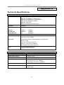
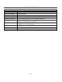
Technical Specifications ..................................................................................................................................... 185
Network Addressing and Protocols..................................................................................................................... 187
IP Addresses.................................................................................................................................................... 187
Internet Protocols ............................................................................................................................................ 192
Packet Headers............................................................................................................................................ 194
The Domain Name System ......................................................................................................................... 198
DHCP Servers ............................................................................................................................................. 199
IP Routing, Multicasting, Multicast Routing and Routing Protocols.................................................................. 200
ARP................................................................................................................................................................. 201
Multicasting .................................................................................................................................................... 202
Internet Group Management Protocol (IGMP) ........................................................................................... 203
Multicast Routing Protocols........................................................................................................................ 205
Routing Protocols........................................................................................................................................ 206
Glossary .............................................................................................................................................................. 209
LIMITED WARRANTY .................................................................................................................................... 211
FCC Warning .............................................................................................................................................. 213
Product Registration ........................................................................................................................................... 217
D-Link Europe Limited Product Warranty ........................................................................................................ 218
International Offices.................................................................................................................................... 228
D-Link DES-3326SR Layer 3 Switch
About This Manual
This manual is organized to provide basic setup information in the beginning chapters, followed by presentation
of more complex material concerning Layer 2 and Later 3 switching functions. Some chapters include
information pertinent to management of specific functions and protocols. This material is intended as a general
introduction to key concepts and is not intended a thorough or exhaustive study network management.
Intended Readers
The DES-3326SR Manual contains information useful for setup and management and of the DES-3326SR
Switch. This manual is intended for network managers familiar with network management concepts and
terminology.
Notes, Notices, and Cautions
NOTE: A NOTE indicates important information that helps you make
better use of your device.
NOTICE: A NOTICE indicates either potential damage to hardware or loss
of data and tells you how to avoid the problem.
CAUTION: A CAUTION indicates a potential for property damage,
personal injury, or death.
vii
D-Link DES-3326SR Layer 3 Switch
Safety Instructions
Use the following safety guidelines to ensure your own personal safety and to help protect your system from
potential damage. Throughout this safety section, the caution icon (
) is used to indicate cautions and
precautions that you need to review and follow.
Safety Cautions
To reduce the risk of bodily injury, electrical shock, fire, and damage to the equipment, observe the following
precautions.
Observe and follow service markings. Do not service any product except as explained in your system
documentation. Opening or removing covers that are marked with the triangular symbol with a lightning bolt
may expose you to electrical shock. Components inside these compartments should be serviced only by a trained
service technician.
If any of the following conditions occur, unplug the product from the electrical outlet and replace the part or
contact your trained service provider:
– The power cable, extension cable, or plug is damaged.
– An object has fallen into the product.
– The product has been exposed to water.
– The product has been dropped or damaged.
– The product does not operate correctly when you follow the operating instructions.
•
Keep your system away from radiators and heat sources. Also, do not block cooling vents.
•
Do not spill food or liquids on your system components, and never operate the product in a wet
environment. If the system gets wet, see the appropriate section in your troubleshooting guide or contact
your trained service provider.
•
Do not push any objects into the openings of your system. Doing so can cause fire or electric shock by
shorting out interior components.
•
Use the product only with approved equipment.
•
Allow the product to cool before removing covers or touching internal components.
•
Operate the product only from the type of external power source indicated on the electrical ratings label.
If you are not sure of the type of power source required, consult your service provider or local power
company.
•
To help avoid damaging your system, be sure the voltage selection Switch (if provided) on the power
supply is set to match the power available at your location:
– 115 volts (V)/60 hertz (Hz) in most of North and South America and some Far Eastern countries such
as South Korea and Taiwan
– 100 V/50 Hz in eastern Japan and 100 V/60 Hz in western Japan
– 230 V/50 Hz in most of Europe, the Middle East, and the Far East
•
Also be sure that attached devices are electrically rated to operate with the power available in your
location.
•
Use only approved power cable(s). If you have not been provided with a power cable for your system or
for any AC-powered option intended for your system, purchase a power cable that is approved for use
in your country. The power cable must be rated for the product and for the voltage and current marked
on the product's electrical ratings label. The voltage and current rating of the cable should be greater
than the ratings marked on the product.
viii
D-Link DES-3326SR Layer 3 Switch
•
To help prevent electric shock, plug the system and peripheral power cables into properly grounded
electrical outlets. These cables are equipped with three-prong plugs to help ensure proper grounding. Do
not use adapter plugs or remove the grounding prong from a cable. If you must use an extension cable,
use a 3-wire cable with properly grounded plugs.
•
Observe extension cable and power strip ratings. Make sure that the total ampere rating of all products
plugged into the extension cable or power strip does not exceed 80 percent of the ampere ratings limit
for the extension cable or power strip.
•
To help protect your system from sudden, transient increases and decreases in electrical power, use a
surge suppressor, line conditioner, or uninterruptible power supply (UPS).
•
Position system cables and power cables carefully; route cables so that they cannot be stepped on or
tripped over. Be sure that nothing rests on any cables.
•
Do not modify power cables or plugs. Consult a licensed electrician or your power company for site
modifications. Always follow your local/national wiring rules.
•
When connecting or disconnecting power to hot-pluggable power supplies, if offered with your system,
observe the following guidelines:
– Install the power supply before connecting the power cable to the power supply.
– Unplug the power cable before removing the power supply.
– If the system has multiple sources of power, disconnect power from the system by
unplugging all power cables from the power supplies.
•
Move products with care; ensure that all casters and/or stabilizers are firmly connected to the system.
Avoid sudden stops and uneven surfaces.
General Precautions for Rack-Mountable Products
Observe the following precautions for rack stability and safety. Also refer to the rack installation documentation
accompanying the system and the rack for specific caution statements and procedures.
Systems are considered to be components in a rack. Thus, "component" refers to any system as well as to various
peripherals or supporting hardware.
CAUTION: Installing systems in a rack without the front and side stabilizers
installed could cause the rack to tip over, potentially resulting in bodily injury under
certain circumstances. Therefore, always install the stabilizers before installing
components in the rack.
After installing system/components in a rack, never pull more than one component
out of the rack on its slide assemblies at one time. The weight of more than one
extended component could cause the rack to tip over and may result in serious
injury.
•
Before working on the rack, make sure that the stabilizers are secured to the rack, extended to the floor,
and that the full weight of the rack rests on the floor. Install front and side stabilizers on a single rack or
front stabilizers for joined multiple racks before working on the rack.
Always load the rack from the bottom up, and load the heaviest item in the rack first.
Make sure that the rack is level and stable before extending a component from the rack.
ix
D-Link DES-3326SR Layer 3 Switch
Use caution when pressing the component rail release latches and sliding a component into or out of a rack; the
slide rails can pinch your fingers.
After a component is inserted into the rack, carefully extend the rail into a locking position, and then slide the
component into the rack.
Do not overload the AC supply branch circuit that provides power to the rack. The total rack load should not
exceed 80 percent of the branch circuit rating.
Ensure that proper airflow is provided to components in the rack.
Do not step on or stand on any component when servicing other components in a rack.
NOTE: A qualified electrician must perform all connections to DC power and to
safety grounds. All electrical wiring must comply with applicable local or national
codes and practices.
CAUTION: Never defeat the ground conductor or operate the equipment in the
absence of a suitably installed ground conductor. Contact the appropriate electrical
inspection authority or an electrician if you are uncertain that suitable grounding is
available.
CAUTION: The system chassis must be positively grounded to the rack cabinet
frame. Do not attempt to connect power to the system until grounding cables are
connected. Completed power and safety ground wiring must be inspected by a
qualified electrical inspector. An energy hazard will exist if the safety ground cable
is omitted or disconnected.
Protecting Against Electrostatic Discharge
Static electricity can harm delicate components inside your system. To prevent static damage, discharge static
electricity from your body before you touch any of the electronic components, such as the microprocessor. You
can do so by periodically touching an unpainted metal surface on the chassis.
You can also take the following steps to prevent damage from electrostatic discharge (ESD):
1. When unpacking a static-sensitive component from its shipping carton, do not remove the component
from the antistatic packing material until you are ready to install the component in your system. Just
before unwrapping the antistatic packaging, be sure to discharge static electricity from your body.
2. When transporting a sensitive component, first place it in an antistatic container or packaging.
3. Handle all sensitive components in a static-safe area. If possible, use antistatic floor pads and
workbench pads and an antistatic grounding strap.
x
D-Link DES-3326SR Layer 3 Switch
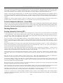
Chapter 1
Introduction
Switch Description
Features
Front Panel Components
LED Indicators
Rear Panel Description
Plug-in Modules
Switch Stacking
Management Options
Switch Description
Layer 3 switching is the integration of two proven technologies: switching and routing. Layer 3 switches are
running the same routing routines and protocols as traditional routers. The main difference between traditional
routing and Layer 3 switching is the addition of a group of Layer 2 switching domains and the execution of
routing routines for most packets via an ASIC – in hardware instead of software.
The DES-3326SR can also replace key traditional routers for data centers and server farms, routing between
these locations and the rest of the network, and providing 24 ports of Layer 2 switching performance combined
with wire-speed routing.
1
D-Link DES-3326SR Layer 3 Switch
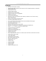
Features
•
8.8 Gbps Switching fabric capacity
•
Supports 802.1w Rapid Spanning Tree and 802.1D STP compatible operation for redundant
back up bridge paths
•
Supports 802.1Q VLAN
•
Supports IGMP snooping
•
Supports 802.1p Priority Queues
•
Supports 802.3ad LACP Link Aggregation
•
Supports port mirroring
•
Access Control Profile (ACL)
•
Multi-layer Access Control (based on MAC address, IP address, VLAN, Protocol, 802.1p,
DSCP/ TCP/UDP port)
•
Quality of Service (QoS) customized control
•
Port Security (MAC address table lock)
•
802.1x (port-based and MAC-based) access control and Radius Client support
•
Administrator-definable port security
•
Per-port bandwidth control
•
Broadcast, Multicast and DLF storm control
•
IEEE 802.3z and IEEE 802.3x compliant Flow Control for all Gigabit ports
•
SNMP v.1, v.2, v.3 network management, RMON support
•
Supports Web-based management.
•
Supports CLI management.
•
Supports BOOTP/DHCP/DNS Relay
•
Supports TFTP upgrade
•
Supports System Log
•
Fully configurable either in-band or out-of-band control via RS-232 console serial connection.
•
Telnet remote control console
•
Traffic Segmentation
•
Simple Network Time Protocol
•
MAC address update notification
•
Web GUI Traffic Monitoring
•
Supports RIP v1, v2
•
Supports OSPF
•
Supports PIM-DM
•
Supports DVMRP
•
•
Supports IGMP
Supports floating static route
2
D-Link DES-3326SR Layer 3 Switch
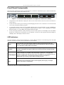
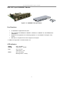
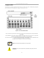
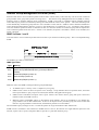
Front Panel Components
The front panel of the Switch consists of LED indicators, an RS-232 communication port, a slide-in module slot,
and 24 (10/100 Mbps) Ethernet/Fast Ethernet ports.
Figure 1 - 1. Front Panel View of the Switch as shipped (no modules are installed)
•
Comprehensive LED indicators display the status of the switch and the network (see the LED Indicators
section below).
•
An RS-232 DCE console port for setting up and managing the switch via a connection to a console terminal
or PC using a terminal emulation program.
•
A front-panel slide-in module slot for Gigabit Ethernet ports can accommodate a 2-port 1000BASE-T
Gigabit Ethernet module, a 2-port 1000BASE-SX Gigabit Ethernet module, a 2-port 1000BASE-LX Gigabit
Ethernet module, or a 2-port GBIC-based Gigabit Ethernet module.
•
Twenty-four high-performance, NWay Ethernet ports all of which operate at 10/100 Mbps with Auto-MDIX
function for connections to end stations, servers and hubs. All ports can auto-negotiate between 10Mbps or
100Mbps, full or half duplex, and flow control.
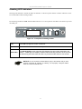
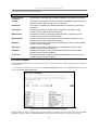
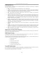
LED Indicators
The LED indicators of the Switch include Power, Console, RPS and Link/Act. The following shows the LED
indicators for the Switch along with an explanation of each indicator.
Power
This indicator on the front panel should be lit during the Power-On Self Test
(POST). It will light green approximately 2 seconds after the Switch is powered
on to indicate the ready state of the device.
Console
This indicator is lit green when the Switch is being managed via out-of-band/local
console management through the RS-232 console port using a straight-through
serial cable.
Link/Act/Speed
These indicators are located to the left and right of each port. The right side
indicator will light when the port has a link of 100 Mbps; the Link indicator will not
light for 10 Mbps links. The LEDs blink whenever there is reception or
transmission (i.e. Activity--Act) of data occurring at a port.
RPS
If the RPS unit is functioning in place of the original power supply, it will light
amber. Otherwise it remains dark.
See below for description of Stack ID LED indicator.
3
D-Link DES-3326SR Layer 3 Switch
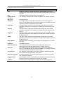
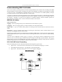
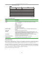
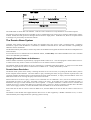
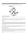
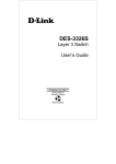
Stacking LED Indicators
Stacking LED indicators include the Stack ID indicator on the front panel and the Link/Act indicators on the
front of the DES-332GS stacking module.
Each stacking module has Link and Act LED indicators on its front panel for the IEEE 1394 IN/OUT pair and
the GBIC port.
Figure 1-2. Front panel of stacking module
Link
The Link LED lights to confirm a valid link.
Act
The ACT LED blinks to indicate activity on the link.
STACK NO.
The Stack Number seven-segment LED displays the Unit number assigned to the
Switch. A zero (0) in the display indicates that the stacking module is in the process
of determining the stack status and has not yet resolved the Switch’s Unit number.
NOTICE: Do not connect the stacked Switch group to the network until you have
properly configured all Switches for stacking. An improperly configured Switch
stack can cause a broadcast storm.
4
D-Link DES-3326SR Layer 3 Switch
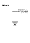
Rear Panel Description
The rear panel of the Switch contains an AC power connector.
Figure 1 - 3. Rear panel view of the Switch
The AC power connector is a standard three-pronged connector that supports the power cord. Plug-in the female
connector of the provided power cord into this socket, and the male side of the cord into a power outlet. The
Switch automatically adjusts its power setting to any supply voltage in the range from 100 ~ 240 VAC at 50 ~ 60
Hz.
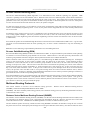
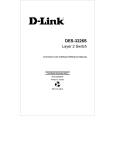
Side Panels
The right side panel of the Switch contains two system fans (see the top part of the diagram below). The left side
panel contains heat vents.
Figure 1 - 4. Side panel views of the Switch
The system fans are used to dissipate heat. The sides of the system also provide heat vents to serve the same
purpose. Do not block these openings, and leave at least 6 inches of space at the rear and sides of the switch for
proper ventilation. Be reminded that without proper heat dissipation and air circulation, system components
might overheat, which could lead to system failure.
5
D-Link DES-3326SR Layer 3 Switch
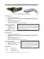
Optional Plug-in Modules
The DES-3326SR 24-port Fast Ethernet Switch is able to accommodate a range of optional plug-in modules in
order to increase functionality and performance. These modules must be purchased separately.
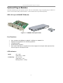
DES-132 2-port 100BASE-TX Module
Figure 1 - 5. 100BASE-TX two-port module
Port Functions
•
Fully compliant with IEEE802.3 10BASE-T, IEEE802.3u 100BASE-TX
•
Supports auto-negotiation in the following operation:
•
10/100M operation
•
Full/Half Duplex operation
•
Flow control: IEEE 802.3x compliant Flow Control support for full-duplex. Back pressure Flow
Control support for half-duplex mode.
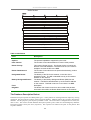
LED Indicators
Speed
Off – 10M
Solid Green – 100M
Link/Activity
Off – No Link
Solid Green – Link
Blinking Green – Activity
6
D-Link DES-3326SR Layer 3 Switch
DES-131F/132F 1/2-port 100BASE-FX Module
Figure 1 - 6. 100BASE-FX two-port module
Port Functions
•
Fully compliant with IEEE802.3u 100BASE-FX
•
Supports auto-negotiation in the following operation: 100M / Full-duplex / Flow control
•
IEEE 802.3x compliant Flow Control support for full-duplex
Connector: SC Type
Distance: 2km
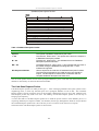
LED Indicators
Link
Off – No Link
Solid Green – Link
Active
Off – No Activity
Blinking Green – Activity
7
D-Link DES-3326SR Layer 3 Switch
DES-131FL/132FL 1/2-port 100BASE-FX Module
Figure 1 - 7. 100BASE-FX module
Port Functions
•
Fully compliant with IEEE802.3u 100BASE-FX
•
Supports auto-negotiation in the following operation: 100M / Full-duplex / Flow control
•
IEEE 802.3x compliant Flow Control support for full-duplex
Connector: SC type
Distance: 15km
LED Indicators
Link
Off – No Link
Solid Green – Link
Active
Off – No Activity
Blinking Green – Activity
8
D-Link DES-3326SR Layer 3 Switch
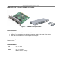
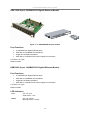
DES-132T 2-port 1000BASE-T Module
Figure 1 - 8. 1000BASE-T two-port module
Port Functions
•
2 1000BASE-T Gigabit Ethernet ports
•
Fully compliant with IEEE802.3 10BASE-T, IEEE802.3u 100BASE-TX, and IEEE802.3ab
1000BASE-T
•
Supports auto-negotiation in the following operation: 10*100/1000M / Full-duplex / Flow
control
•
IEEE 802.3x compliant Flow Control support for full-duplex
* 10 Mbps not supported in firmware release 4.01
LED Indicators
Speed
(1000M)
Off – 10/100M
Solid Green – 1000M
Link
Off – No Link
Solid Green – Link
Active
Off – No Activity
Blinking Green – Activity
9
D-Link DES-3326SR Layer 3 Switch
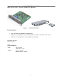
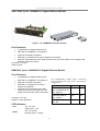
DES-132G 2-port 1000BASE-SX Gigabit Ethernet Module
Figure 1 - 9. 1000BASE-SX two-port module
Port Functions
•
2 1000BASE-SX Gigabit Ethernet ports
•
IEEE 802.3z 1000BASE-SX compliance
•
Supports Full-duplex operations
•
IEEE 802.3x compliant Flow Control support for full-duplex
Connector: SC Type
Distance: 550m
DEM-320S 2-port 1000BASE-SX Gigabit Ethernet Module
Port Functions
•
2 1000BASE-SX Gigabit Ethernet ports
•
IEEE 802.3z 1000BASE-SX compliance
•
Supports Full-duplex operations
•
IEEE 802.3x compliant Flow Control support for full-duplex
Connector: SC Type
Distance: 550m
LED Indicators
Link
Off – No Link
Solid Green – Link
Active
Off – No Activity
Blinking Green – Activity
10
D-Link DES-3326SR Layer 3 Switch
DES-132GL 2-port 1000BASE-LX Gigabit Ethernet Module
Figure 1 - 10. 1000BASE-LX two-port module
Port Functions
•
2 1000BASE-LX Gigabit Ethernet ports
•
IEEE 802.3z 1000BASE-LX compliance
•
Supports Full-duplex operations
•
IEEE 802.3x compliant Flow Control support for full-duplex
•
Supports multi-mode fiber optic cable connections of up to 550 meters or 5 km single-mode
fiber-optic cable connections.
Connector: SC Type
Distance: 5km
DEM-320L 2-port 1000BASE-LX Gigabit Ethernet Module
Port Functions
•
2 1000BASE-LX Gigabit Ethernet ports
•
IEEE 802.3z 1000BASE-LX compliance
•
Supports Full-duplex operations
•
IEEE 802.3x compliant Flow Control
support for full-duplex
•
Supports single-mode fiber optic cable
connections of up to 550 meters or 5 km
single-mode fiber-optic cable connections.
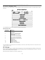
The 1000BASE-SX module allows connections
using multi-mode fiber optic cable in the following
configurations:
Connector: SC Type
Distance: 10km (9/125um)
LED Indicators
Link
Off – No Link
Solid Green – Link
Active
Off – No Activity
Blinking Green – Activity
11
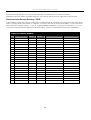
62.5µm
50µm
Modal bandwidth
(min. overfilled launch)
Unit: MHz*km
200
500
Operating distance
Unit: meters
275
550
Channel insertion loss
Unit: dB
2.53
3.43
D-Link DES-3326SR Layer 3 Switch
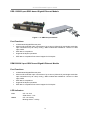
DES-132GB 2-port GBIC-based Gigabit Ethernet Module
Figure 1 - 11. GBIC two-port module
Port Functions
•
2 GBIC-based Gigabit Ethernet ports
•
Allows multi-mode fiber optic connections of up to 550 m (SX and LX) and single-mode fiber
optic connections of up to 5 km (LX only). GBIC modules are available in –SX and –LX fiber
optic media.
•
IEEE 802.3z compliance
•
Supports full-duplex operations
•
IEEE 802.3x compliant Flow Control support for full-duplex
DEM-320GH 2-port GBIC-based Gigabit Ethernet Module
Port Functions
•
2 GBIC-based Gigabit Ethernet ports
•
Allows multi-mode fiber optic connections of up to 550 m (SX and LX) and single-mode fiber
optic connections of up to 5 km (LX only). GBIC modules are available in –SX and –LX fiber
optic media.
•
IEEE 802.3z compliance
•
Supports full-duplex operations
•
IEEE 802.3x compliant Flow Control support for full-duplex
LED Indicators
Link
Off – No Link
Solid Green – Link
Active
Off – No Activity
Blinking Green – Activity
12
D-Link DES-3326SR Layer 3 Switch
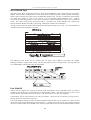
DES-332GS 1-port GBIC-Based Gigabit Ethernet Switch and stacking Module
Figure 1 - 12. Stacking Module with one GBIC port
Port Functions
•
•
•
•
•
1 GBIC-Based Gigabit Ethernet port
Allows multi-mode fiber optic connections of up to 550 m (SX and LX) and single-mode fiber
optic connections of up to 5 km (LX only). GBIC modules are available in –SX and –LX fiber
optic media.
IEEE 802.3z 1000BASE-SX compliance
Supports Full-duplex operations
IEEE 802.3x compliant Flow Control support for full-duplex
Stacking Port Function
•
•
•
1 transmitting port and 1
receiving port
IEEE1394.b compliance
Forwarding rate up to
965Mbps
The stacking ports are marked IN and OUT. The IEEE 1394 compliant
cable must be connected from an IN port on one Switch to an OUT port on
the next Switch in the stack. The last two Switches (at the top and bottom of
the stack) must also be connected from the IN port on one Switch to the
OUT port on the other Switch. In this way, a loop is made such that all of
the Switches in the Switch stack have the IN stacking port connected to
another Switch’s OUT stacking port.
DEM-320GS 1-port GBIC-Based Gigabit Ethernet Switch and stacking Module
Port Functions
•
•
•
•
•
1 GBIC-Based Gigabit Ethernet port
Allows multi-mode fiber optic connections of up to 550 m (SX and LX) and single-mode fiber
optic connections of up to 5 km (LX only). GBIC modules are available in –SX and –LX fiber
optic media.
IEEE 802.3z 1000BASE-SX compliance
Supports Full-duplex operations
IEEE 802.3x compliant Flow Control support for full-duplex
Stacking Port Function
•
•
•
1 transmitting port and 1 receiving port
IEEE1394.b compliance
Forwarding rate up to 965Mbps
LED Indicators*
Link
Off – No Link
Solid Green – Link
Active
Off – No Activity
Blinking Green – Activity
The optional Stacking Module allows up to eight DES-3326SR
Switches to be interconnected via their individual stacking
modules. This forms an eight-Switch stack that can then be
managed and configured as thought the entire stack were a
single Switch. The Switch stack is then accessed through a
single IP address or alternatively, through the master Switch’s
serial port (via the management station’s console and the
Switch’s Command Line Interface).
*See Stacking LED Indicators on page 4 for details on the stacking port display.
13
D-Link DES-3326SR Layer 3 Switch
Switch Stacking
The optional Stacking Module allows up to thirteen DES-3326SR Switches to be interconnected via their
individual Stacking Modules. This forms a thirteen-switch stack that can then be managed and configured as
thought the entire stack were a single switch. The switch stack is then accessed through a single IP address or
alternatively, through the master switch’s serial port (via the management station’s console and the switch’s
Command Line Interface).
The stacking ports are marked IN and OUT. The IEEE 1394 compliant cable must be connected from an IN
port on one switch to an OUT port on the next switch in the stack. In this way, a loop is made such that all of
the switches in the switch stack have the IN stacking port connected to another switch’s OUT stacking port. See
Connecting Stacked Switch Groups on page 23 for an illustration of a properly connected stack.
Stack order can be automatically determined, the lowest MAC address is elected as the Master Switch and the
remaining stack order depends on how the Switches are connected. However, it may be best to configure a
Master for the group first using the CLI interface, and then connect the stack accordingly.
NOTE: Stacking mode is configured using the CLI command config
stacking mode. The default settings allow the switch to function as a
standalone device or as a member of a stacked group.
14
D-Link DES-3326SR Layer 3 Switch
Management Options
The system may be managed out-of-band through the console port on the front panel or in-band using Telnet, a
web browser or SNMP-based management.
Web-based Management Interface
After you have successfully installed the Switch, you can configure the Switch, monitor the LED panel, and
display statistics graphically using a web browser, such as Netscape Navigator (version 6.2 and higher) or
Microsoft® Internet Explorer (version 5.0).
NOTE: To access the Switch through a web browser, the computer
running the web browser must have IP-based network access to the
Switch.
Command Line Console Interface through the Serial Port or Telnet
You can also connect a computer or terminal to the serial console port or use Telnet to access the Switch. The
command-line-driven interface provides complete access to all Switch management features. For a full list of
commands, see the Command Line Reference Manual, which is included on the documentation CD.
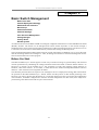
SNMP-Based Management
You can manage the Switch with an SNMP-compatible console program. The Switch is supports SNMP version
1.0, version 2.0 and version 3.0. The SNMP agent decodes the incoming SNMP messages and responds to
requests with MIB objects stored in the database. The SNMP agent updates the MIB objects to generate statistics
and counters.
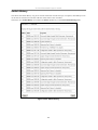
The Switch supports a comprehensive set of MIB extensions:
•
•
•
•
•
•
•
•
•
•
•
•
•
•
•
•
•
•
•
RFC 1643 Ether-like MIB
RFC 1724 RIPv2 MIB
RFC 1757 RMON
RFC 1850 OSPF MIB
RFC 1907 SNMPv2 MIB
RFC 2021 RMON II MIB
RFC 2096 IP-FORWARD MIB
RFC 2233 IF-MIB
RFC 2358 Ethernet-Link MIB
RFC 2573 SNMP Notification and Target MIB
RFC 2574 SNMP User-based SM MIB
RFC 2575 SNMP View-based ACM MIB
RFC 2674 802.1p and 802.1q Bridge MIB
RFC 2737 Entity MIB
RFC 2932 IPMROUTE STD MIB
RFC 2933 IGMP MIB
RFC 2934 PIM MIB
IEEE8021-PAE 802.1x PAE MIB
D-Link Enterprise MIB
15
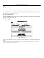
D-Link DES-3326SR Layer 3 Switch
Chapter 2
Installation
Package Contents
Before You Connect to the Network
Connecting the Console Port
Password Protection
SNMP Settings
IP Address Assignment
Connecting Stacked Switch Groups
Configuring a Switch Group for Stacking
Connecting Devices to the Switch
Package Contents
Before you begin installing the Switch, confirm that your package contains the following items:
•
One DES-3326SR Layer 3 Switch
•
Mounting kit: 2 mounting brackets and screws
•
Four rubber feet with adhesive backing
•
One AC power cord
•
This Manual and CLI Reference on the documentation CD
16
D-Link DES-3326SR Layer 3 Switch
Before You Connect to the Network
Before you connect to the network, you must install the Switch on a flat surface or in a rack, set up a terminal
emulation program, plug in the power cord, and then set up a password and IP address.
NOTICE: Do not connect the Switch to the network until you have established the correct IP
settings, user accounts and proper stacking configuration (if the Switch is stacked).
Connecting the Console Port
The Switch provides an RS-232 serial port that enables a connection to a computer or terminal for monitoring
and configuring the Switch. This port is a female DB-9 connector, implemented as a Data Circuit-terminating
Equipment (DCE) connection.
To use the console port, you need the following equipment:
•
A terminal or a computer with both a serial port and the ability to emulate a terminal
•
A null modem or crossover RS-232 cable with a female DB-9 connector for the console port on the
Switch
To connect a terminal to the console port:
1.
Connect the female connector of the RS-232 cable directly to the console port on the Switch, and
tighten the captive retaining screws.
2.
Connect the other end of the cable to a terminal or to the serial connector of a computer running
terminal emulation software. Set the terminal emulation software as follows:
a.
Select the appropriate serial port (COM port 1 or COM port 2).
b.
Set the data rate to 9600 baud.
c.
Set the data format to 8 data bits, 1 stop bit, and no parity.
d.
Set flow control to none.
e.
Under Properties, select VT100 for Emulation mode.
f.
Select Terminal keys for Function, Arrow, and Ctrl keys. Ensure that you select Terminal keys
(not Windows keys).
NOTICE: When you use HyperTerminal with the Microsoft® Windows® 2000
operating system, ensure that you have Windows 2000 Service Pack 2 or
later installed. Windows 2000 Service Pack 2 allows you to use arrow keys in
HyperTerminal’s VT100 emulation. See www.microsoft.com for information
on Windows 2000 service packs.
g.
After you have correctly set up the terminal, plug the power cable into the power receptacle on the
back of the Switch. The boot sequence appears in the terminal.
h.
After the boot sequence completes, the console login screen displays.
i.
If you have not logged into the command line interface (CLI) program, press the Enter key at the
User name and password prompts. There is no default user name and password for the Switch, user
names and passwords must first be created by the administrator. If you have previously set up user
accounts, log in and continue to configure the Switch.
j.
Enter the commands to complete your desired tasks. Many commands require administrator-level
access privileges. Read the next section for more information on setting up user accounts. See the
Command Line Reference on the documentation CD for a list of all commands and additional
information on using the CLI.
k.
When you have completed your tasks, exit the session with the logout command or close the
emulator program.
17
D-Link DES-3326SR Layer 3 Switch
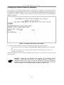
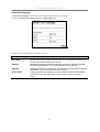
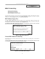
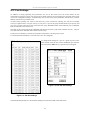
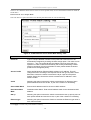
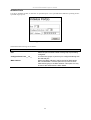
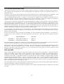
Password Protection
The DES-3326SR does not have a default user name and password. One of the first tasks when settings up the
Switch is to create user accounts. If you log in using a predefined administrator-level user name you have
privileged access to the Switch’s management software.
After your initial login, define new passwords for both default user names to prevent unauthorized access to the
Switch, and record the passwords for future reference.
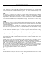
To create an administrator-level account for the Switch, do the following:
1.
At the CLI login prompt, enter create account admin followed by the <user name> and press
the Enter key.
2.
You will be asked to provide a password. Type the <password> used for the administrator
account being created and press the Enter key.
3.
You will be prompted to enter the same password again to verify it. Type the same password
and press the Enter key.
4.
Successful creation of the new administrator account will be verified by a Success message.
User names and passwords can be up to 15 characters in length.
NOTE: Passwords are case sensitive.
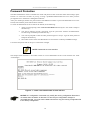
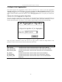
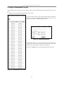
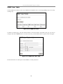
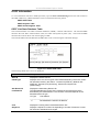
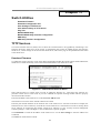
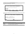
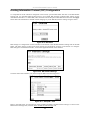
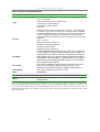
The sample below illustrates a successful creation of a new administrator-level account with the user name
“newmanager”.
Figure 2 - 1. Create a new administrator account with CLI
NOTICE: CLI configuration commands only modify the running configuration file and are
not saved when the Switch is rebooted. To save all your configuration changes in
nonvolatile storage, you must use the save command to copy the running configuration file
to the startup configuration.
18
D-Link DES-3326SR Layer 3 Switch
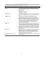
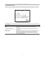
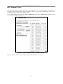
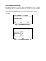
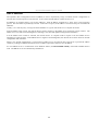
IP Address Assignment
Each Switch must be assigned its own IP Address, which is used for communication with an SNMP network
manager or other TCP/IP application (for example BOOTP, TFTP). The Switch’s default IP address is
10.90.90.90. You can change the default Switch IP address to meet the specification of your networking address
scheme.
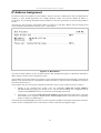
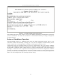
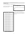
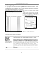
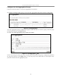
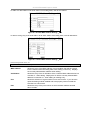
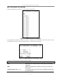
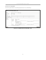
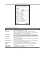
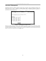
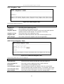
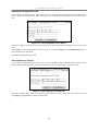
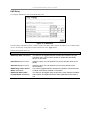
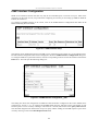
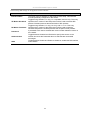
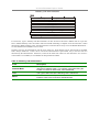
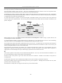
The Switch is also assigned a unique MAC address by the factory. This MAC address cannot be changed, and
can be found from the initial boot console screen – shown below.
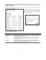
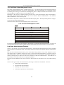
Figure 2 - 2. Boot Screen
The Switch’s MAC address can also be found from the Web management program on the Switch Information
(Basic Settings) window on the Configuration menu.
The IP address for the Switch must be set before it can be managed with the Web-based manager. The Switch IP
address can be automatically set using BOOTP or DHCP protocols, in which case the actual address assigned to
the Switch must be known.
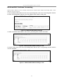
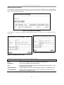
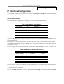
The IP address may be set using the Command Line Interface (CLI) over the console serial port as follows:
1.
Starting at the command line prompt, enter the commands config ipif System ipaddress
xxx.xxx.xxx.xxx/yyy.yyy.yyy.yyy. Where the x’s represent the IP address to be assigned to the IP
interface named System and the y’s represent the corresponding subnet mask.
2.
Alternatively, you can enter config ipif System ipaddress xxx.xxx.xxx.xxx/z. Where the x’s represent
the IP address to be assigned to the IP interface named System and the z represents the corresponding
number of subnets in CIDR notation.
The IP interface named System on the Switch can be assigned an IP address and subnet mask which can then be
used to connect a management station to the Switch’s Telnet or Web-based management agent.
19
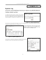
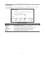
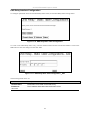
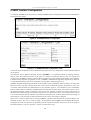
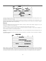
D-Link DES-3326SR Layer 3 Switch
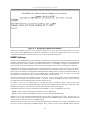
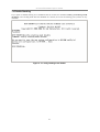
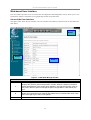
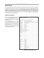
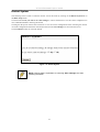
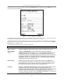
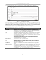
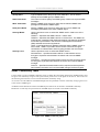
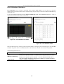
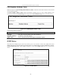
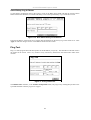
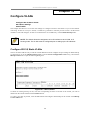
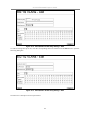
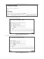
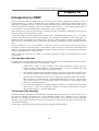
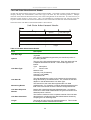
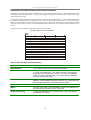
Figure 2 - 3. Assigning the Switch an IP Address
In the above example, the Switch was assigned an IP address of 10.10.1.100 with a subnet mask of 255.0.0.0.
The system message Success indicates that the command was executed successfully. The Switch can now be
configured and managed via Telnet and the CLI or via the Web-based management.
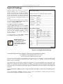
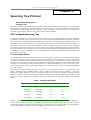
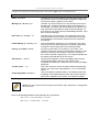
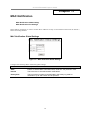
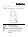
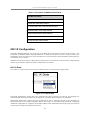
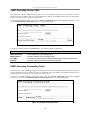
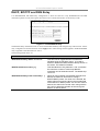
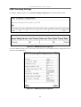
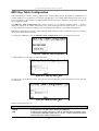
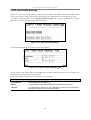
SNMP Settings
Simple Network Management Protocol (SNMP) is an OSI Layer 7 (Application Layer) designed specifically for
managing and monitoring network devices. SNMP enables network management stations to read and modify the
settings of gateways, routers, Switches, and other network devices. Use SNMP to configure system features for
proper operation, monitor performance and detect potential problems in the Switch, Switch group or network.
Managed devices that support SNMP include software (referred to as an agent), which runs locally on the device.
A defined set of variables (managed objects) is maintained by the SNMP agent and used to manage the device.
These objects are defined in a Management Information Base (MIB), which provides a standard presentation of
the information controlled by the on-board SNMP agent. SNMP defines both the format of the MIB
specifications and the protocol used to access this information over the network.
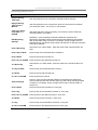
The DES-3326SR supports the SNMP versions 1, 2c, and 3. You can specify which version of the SNMP you
want to use to monitor and control the Switch. The three versions of SNMP vary in the level of security
provided between the management station and the network device.
In SNMP v.1 and v.2, user authentication is accomplished using ‘community strings’, which function like
passwords. The remote user SNMP application and the Switch SNMP must use the same community string.
SNMP packets from any station that has not been authenticated are ignored (dropped).
The default community strings for the Switch used for SNMP v.1 and v.2 management access are:
public - Allows authorized management stations to retrieve MIB objects.
private - Allows authorized management stations to retrieve and modify MIB objects.
SNMP v.3 uses a more sophisticated authentication process that is separated into two parts. The first part is to
maintain a list of users and their attributes that are allowed to act as SNMP managers. The second part describes
what each user on that list can do as an SNMP manager.
The Switch allows groups of users to be listed and configured with a shared set of privileges. The SNMP version
may also be set for a listed group of SNMP managers. Thus, you may create a group of SNMP managers that are
20
D-Link DES-3326SR Layer 3 Switch
allowed to view read-only information or receive traps using SNMP v.1 while assigning a higher level of
security to another group, granting read/write privileges using SNMP v.3.
Using SNMP v.3 individual users or groups of SNMP managers can be allowed to perform or be restricted from
performing specific SNMP management functions. The functions allowed or restricted are defined using the
Object Identifier (OID) associated with a specific MIB. An additional layer of security is available for SNMP v.3
in that SNMP messages may be encrypted. To read more about how to configure SNMP v.3 settings for the
Switch read the next section, Management.
Traps
Traps are messages that alert network personnel of events that occur on the Switch. The events can be as serious
as a reboot (someone accidentally turned OFF the Switch), or less serious like a port status change. The Switch
generates traps and sends them to the trap recipient (or network manager). Typical traps include trap messages
for Authentication Failure or Topology Change.
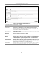
MIBs
Management and counter information are stored by the Switch in the Management Information Base (MIB). The
Switch uses the standard MIB-II Management Information Base module. Consequently, values for MIB objects
can be retrieved from any SNMP-based network management software. In addition to the standard MIB-II, the
Switch also supports its own proprietary enterprise MIB as an extended Management Information Base. The
proprietary MIB may also be retrieved by specifying the MIB Object Identifier. MIB values can be either readonly or read-write.
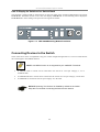
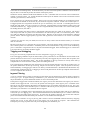
Installing the Switch without the Rack
The Switch is supplied with rubber feet for stationing it on a flat surface and mounting brackets and screws for
mounting the Switch in a rack. If you intend to use a stacked Switch arrangement, place the Master unit in the
top position so that it may be easily identified.
1.
Install the Switch on a level surface that can safely support the weight of the Switch and its attached
cables. The Switch must have adequate space for ventilation and for accessing cable connectors.
2.
Set the Switch on a flat surface and check for proper ventilation. Allow at least 5 cm (2 inches) on each
side of the Switch and 15 cm (6 inches) at the back for the power cable.
3.
Attach the rubber feet on the marked locations on the bottom of the chassis.
4.
The rubber feet, although optional, are recommended to keep the unit from slipping.
Figure 2-4. Install rubber feet for installations with or without a rack
21
D-Link DES-3326SR Layer 3 Switch
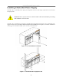
Installing the Switch in a Rack
You can install the Switch in most standard 19-inch (48.3-cm) racks. Refer to the illustrations below.
1.
Use the supplied screws to attach a mounting bracket to each side of the Switch.
2.
Align the holes in the mounting bracket with the holes in the rack.
3.
Insert and tighten two screws through each of the mounting brackets.
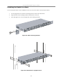
Figure 2-5. Attach mounting brackets
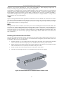
Figure 2-6. Install Switch in equipment rack
22
D-Link DES-3326SR Layer 3 Switch
Connecting Stacked Switch Groups
A total of up to thirteen DES-3326SR Switches can be stacked, using the optional stacking module, into a Switch
stack that can then be configured and managed as a single unit. The Web-based Management agent of the
Master Switch can configure and manage all of the Switches in a Switch stack − using a single IP address (the IP
address of the Master Switch).
The Command Line Interface (CLI) can be also be used to manage and configure all of the Switches in a Switch
stack − from the serial port on the Master Switch. The CLI can also be used to configure and manage the switch
stack via the TELNET protocol − using a single IP address (the IP address of the Master Switch).
NOTICE: Do not connect the stacked Switch group to the network until you have
properly configured all Switches for stacking. An improperly configured Switch
stack can cause a broadcast storm.
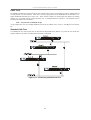
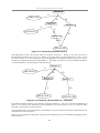
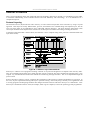
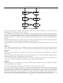
Stacking Connections with IEEE 1394 Cabling
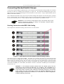
The example below illustrates stacking connections for a six-switch stack.
Figure 2 - 7. Switch Stack connections between optional stacking modules
The stacking ports are marked IN and OUT. The IEEE 1394 compliant cable must be connected from an IN
port on one switch to an OUT port on the next switch in the stack. Connect the last Switch in the stack to the
Master switch to complete the loop. This will create a ring topology for the stacked group. The logical stack
order is determined by stacking connection in relation to the Master. The Number 2 Switch will be the Switch
connected to the OUT port on the Master, the Number 3 Switch is connected to the OUT port on the Number 2
Switch, and so on.
NOTICE: If a link between stacked switches fails the stacked group must be
connected to work around the failed link. Any change to the composition of a
stacked switch group or any failure of a stacking port will trigger an automatic restart
of the entire stack. Therefore, after making the necessary changes to the stacked
group, restart the entire stack again so the new stacking relationship may be
negotiated again. Read the CLI Reference for information on manual configuration
of Switch Stacking Commands.
23
D-Link DES-3326SR Layer 3 Switch
Notes on Stacking Switches
By default, the Switch configuration settings allow it to operate as a standalone device, or in a stacked group. It
is not necessary to change any settings for the Switch to function in either capacity. However, it is recommended
that a Master Switch be manually designated for a stacked group when it is first set up.
Keep in mind the following guidelines when setting up a Switch stack:
•
A Switch that is not connected to another DES-3326SR through the stacking ports will operate as a
standalone Switch even if the stacking mode is enabled as a Master or in Auto mode.
•
In order to easily identify the Master Switch, place the designated Master unit at the top of the stack.
Use the auto stacking mode for the remaining Switches. Stack order is determined by how the Switches
are connected in relation to the Master.
•
If a link between stacked switches fails the stacked group must be connected to work around the failed
link. As with any changes in the composition of the stacked switch group, the new stacking relationship
must be negotiated. Any change to the composition of a stacked switch group or any failure of a
stacking port will cause the entire stack to restart and negotiate the new stacking composition.
The slave Switch units must meet the following criteria:
•
All additional slave Switches must be the same model, that is (at the time of the writing of this manual),
the slaves must be all DES-3326SR Switches. The slave unit types cannot be mixed within a single
stacked group.
•
All Switches must have the same firmware version loaded to operate in a stacked group.
•
A Master should be designated for the group. If the remaining Switches are using the default stacking
mode configuration, the Master will be recognized and the stack order established automatically.
Stacking mode can be changed using the CLI. The possible stacking configuration modes are as follows:
Disabled: This forces the Switch to operate as a standalone device. In standalone mode the Switch functions as a
standalone device even if a stacking module is installed. To force standalone operation it is necessary to use the
CLI command config stacking mode disable. A Switch that has stacking mode disabled should
never connect to another Switch through stacking ports. See below for notes on standalone operation.
NOTICE: Do not use stacking ports on a Switch that has the stacking mode disabled.
Enabled: Stacking mode is enabled by default. When enabled the Switch can operate as a standalone device or it
can operate with other DES-3326SR Switches in a properly connected stacked group. Stacking must be enabled
for the Switch function in a stacked arrangement with other DES-3326SR Switches. When stacking mode is
enabled it must also be configured to function in auto, master or slave mode.
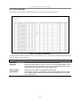
Auto: This is the default stacking mode setting for the DES-3326SR. In auto stacking mode the Switch is
eligible for stacking or it can operate as a standalone device. If a DES-3326SR Switch stack is connected and all
units are configured to operate in auto stacking mode, the master-slave relationships is determined automatically.
However, as previously noted, it is better to manually designate a Switch (at the top of the stack) to be the
Master Switch and restart the entire stack. See the instructions below for details on how to manually designate a
Master.
Master: The auto mode described above may be overridden so that a properly connected Switch in a stack may
be forced into master mode. Only one Switch in a stack may act as the master and all configuration settings for
the stacked group - including stacking configuration - are saved in configuration files in the master Switch. The
stack is managed as a single entity through the master. It may be convenient to place the master unit in the
upper-most slot of a stacked group to visually distinguish it form the slave units. The master unit should be used
to uplink the stack group to the backbone. If the master unit fails or is replaced for any reason, it is possible to
load configuration files saved from the original master unit in order to continue operation with identical settings.
Slave: The auto mode may be overridden to force the Switch to operate in slave mode. When the Switch is in
slave mode, it is ineligible to function as a master and all configuration, is done through the Master unit. A
Master Switch must be properly connected to the stack for a Switch to operate in slave mode.
24
D-Link DES-3326SR Layer 3 Switch
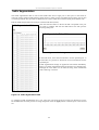
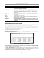
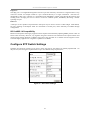
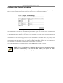
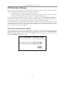
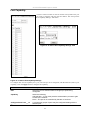
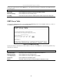
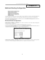
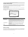
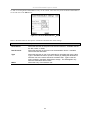
Configuring a Switch Group for Stacking
In order to set up a stack of DES-3326SR Switches it is only necessary to designate a single Switch as Master if
all the Switches are using the default auto setting for the stacking mode configuration. Stacking mode may also
be disabled for standalone operation, however it is not necessary to disable stacking to use the Switch as a
standalone device. When the stacking mode is enabled, the options available for operation are auto(default),
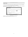
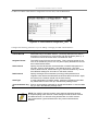
master and slave.
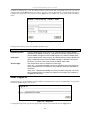
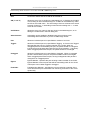
Figure 2 - 8. Stacking mode options when enabled
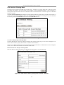
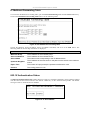
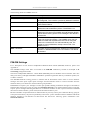
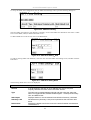
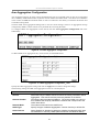
To configure the DES-3326SR to function in a stacked group as the Master, do the following:
1. At the CLI login prompt, enter config stacking mode enable master and press the Enter
key.
2. You will be prompted to save the stacking mode configuration. Press the Y key (yes) to save the
stacking mode configuration.
Successful configuration will be verified by a Success message. It takes a few seconds for the change to be saved
and to take effect.
NOTICE: A Switch that has previously been operating as a standalone Switch
maintains a configuration file used only for standalone operation. Therefore if a
standalone Switch is later used in a stack, the standalone configuration file is NOT
loaded upon restart. New configuration settings must be configured for any Switch that
makes a transition form standalone operation to Master of a Switch stack.
25
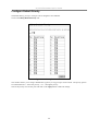
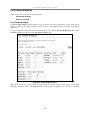
D-Link DES-3326SR Layer 3 Switch
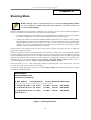
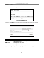
Figure 2 - 9. config stacking mode enable master
The remaining slave units in the stack can be set to the default configuration to automatically recognize the
presence of the Master. The stack order will likewise be determined automatically according to the physical
stacking connection.
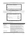
Notes on Standalone Operation
The DES-3326SR operates as a standalone Switch using the default configuration settings when it is not
connected to another Switch through a stacking port. It may also be configured to disable stacking for the
Switch, in which case, if a stacking module is installed, the stacking port should not be used.
Configuration settings for a standalone Switch are saved in a configuration file that is only used for standalone
operation. This standalone configuration is used whenever the Switch is used as a standalone Switch, even if the
stacking mode is enabled for Auto or Master. Likewise, a separate configuration file is used when a Switch is
operating as a stacked unit. This is important if the stacking function of a Switch is changed from standalone
operation. For example, if a standalone Switch is later used as a Master Switch for a stack, it will NOT load the
previously created standalone configuration file. A Switch that makes a transition from standalone operation to
Master, must be reconfigured with new IP settings and other settings.
26
D-Link DES-3326SR Layer 3 Switch
To Disable Stacking
If you prefer to disable stacking for a standalone Switch, use the CLI command config stacking mode
disable. Once stacking mode has been disabled on a Switch, do not use the stacking ports (if there are any
installed).
Figure 2 - 10. config stacking mode disable
27
D-Link DES-3326SR Layer 3 Switch
Unit ID Display for Switches in a Switch Stack
The Stack ID 7-segment LED (as shown below) on the front panel of the stacking module displays the logical
STACK NO. The Master Switch in the stack will display STACK NO. 1. The remaining slaves display the
STACK NO. 2 to 13 according to the position in the logical stack order.
Figure 2 - 11. DES-3326SR Stacking Module Front Panel
Connecting Devices to the Switch
These connections can be accomplished at any port in either straight-through cable or a crossover cable because
the switch supports Auto-MDIX function.
NOTE: Auto-MDIX function is not supported by the 100BASE-TX module.
•
A 10BASE-T hub or switch can be connected to the switch via a two-pair Category 3, 4 or 5
UTP/STP cable.
•
A 100BASE-TX hub or switch can be connected to the switch via a two-pair Category 5 UTP cable.
•
A 1000BASE-T connections use two-pair Category 5e UTP cable.
NOTICE: Spanning Tree Protocol is disabled by default on the Switch.
Keep this in mind when connecting the Switch to the network.
28
D-Link DES-3326SR Layer 3 Switch
Installing a Redundant Power Supply
The DPS-200 is a redundant power-supply unit designed to conform to the voltage requirements of the switches
being supported.
CAUTION: The AC power cord for the switch should be disconnected before proceeding
with installation of the DPS-200.
The DPS-900 is a standard-size rack mount (5 standard units in height) designed to hold up to 8 redundant power
supplies. These can be used with the DPS-200 and DPS-500 redundant power supplies, or a install a combination
of both types. For the DES-3326SR Layer 3 Switch, use the DPS-200.
Figure 2 - 12. Install DPS-200 in DPS-900
Figure 2 - 13. Install DPS-900 in equipment rack
29
D-Link DES-3326SR Layer 3 Switch
Connect to RPS
The DPS-200 is connected to the Master Switch using a 14-pin DC power cable. A standard, three-pronged AC
power cable connects the redundant power supply to the main power source.
Figure 2 - 14. Connect RPS to Switch
Insert one end of the 14-pin DC power cable into the receptacle on the switch and the other end into the redundant
power supply.
Using a standard AC power cable, connect the redundant power supply to the main AC power source. A green LED
on the front of the DPS-200 will glow to indicate a successful connection.
Re-connect the switch to the AC power source. On certain switches, such as the DES-3326SR, an LED indicator will
show that a redundant power supply is now in operation.
No change in switch configuration is necessary for this installation.
NOTE: See the DPS-200 documentation for more information.
CAUTION: Do not use the Switch with any redundant power system other than
the DPS-200.
30
D-Link DES-3326SR Layer 3 Switch
Chapter 3
Basic Switch Management
Before You Start
General Deployment Strategy
Web-based User Interface
Basic Setup
Switch Information
Switch IP Settings
User Accounts Management
Saving Changes
Factory Reset
Restart System
All software function of the DES-3326SR can managed, configured and monitored via the embedded web-based
(HTML) interface. The Switch can be managed from remote stations anywhere on the network through a
standard browser such as Netscape Navigator/Communicator or Microsoft Internet Explorer. The browser acts as
a universal access tool and can communicate directly with the Switch using the HTTP protocol.
The web-based management module and the Console program (and Telnet) are different ways to access the same
internal Switching software and configure it. Thus, all settings encountered in web-based management are the
same as those found in the console program.
Before You Start
The DES-3326SR Layer 3 Switch supports a wide array of functions and gives great flexibility and increased
network performance by eliminating the routing bottleneck between the WAN or Internet and the Intranet. Its
function in a network can be thought of as a new generation of router that performs routing functions in
hardware, rather than software. It is in effect, a router that also has numerous independent Ethernet collision
domains – each of which can be assigned an IP subnet.
This flexibility and rich feature set requires a bit of thought to arrive at a deployment strategy that will maximize
the potential of the DES-3326SR Layer 3 Switch. Please read the portions of this manual pertaining to the
functions you wish to perform with the Switch. It is especially important to map out VLANs and configuration
of IP interfaces, and OSPF configuration in advance of actual configuration. For this reason, these subjects are
presented in greater detail in the final two parts of this manual.
31
D-Link DES-3326SR Layer 3 Switch
General Deployment Strategy
1.
Determine how the network would be best segmented. This is probably done using VLANs in an
existing layer 2 Switched network.
2.
Develop an IP addressing scheme. This involves allocating a block of IP addresses to each network
segment. Each network subnet is then assigned a network address and a subnet mask. Background
information regarding IP addresses is presented in Part IV of this guide.
3.
Determine which network resources must be shared by the subnets. Shared resources may be connected
directly to Layer 3 Switches. Static routes to each of the shared resources should be determined.
4.
Determine how each subnet will communicate with the WAN or Internet. Again, static routes should
be determined and default gateways identified.
5.
Develop a security scheme. Some subnets on the network need more security or should be isolated
from the other subnets. IP or MAC filtering can be used. Also, one or more VLANs on the Layer 3
Switch can be configured without an IP subnet – in which case, these VLANs will function as a layer 2
VLAN and would require an external router to connect to the rest of the network.
6.
Develop a policy scheme. Some subnets will have a greater need for multicasting bandwidth, for
example. A policy is a mechanism to alter the normal packet forwarding in a network device, and can
be used to intelligently allocate bandwidth to time-critical applications such as the integration of voice,
video, and data on the network.
7.
Develop a redundancy scheme. Planning redundant links and routes to network critical resources can
save valuable time in case of a link or device failure. The DES-3326SR Spanning Tree function can be
used to block the redundant link until it is needed.
VLAN Setup
VLANs setup in Layer 3 Switching is more complicated than in conventional Layer 2 Switching environments.
Be sure to carefully plan the VLAN/IP interface arrangement for the network before configuring the VLANs and
IP interface associations.
Please read the material provided in later chapters about setting up VLANs in a Layer 3 Switch for more
information.
Defining Static Routes
Routes between the IP interfaces and a default gateway or other router with a WAN connection should be
determined beforehand and entered into the static/default routing table on the DES-3326SR.
Static route configuration and related topics are discussed at length in later chapters.
32
D-Link DES-3326SR Layer 3 Switch
Web-based User Interface
The user interface provides access to various Switch configuration and management screens, allows you to view
performance statistics, and permits you to graphically monitor the system status.
Areas of the User Interface
The figure below shows the user interface. The user interface is divided into 3 distinct areas as described in the
table below.
Area 1
Area 2
Area 3
Figure 3- 1. Main Web-Manager window
Area
Function
1
Presents a graphical near real-time image of the front panel of the Switch. This area
displays the Switch’s ports and expansion modules. When the Switch is stacked a
virtual representation of the Switch stack appears in the right hand portion. Click on
the ports in the front panel to manage the port’s configuration or view data for the
port.
2
Select the menu or window to be displayed. The folder icons can be opened to
display the hyperlinked menu buttons and subdirectorys contained within them. Click
the D-Link logo to go to the D-Link website.
3
Presents the information or menu selected for configuration or display.
33
D-Link DES-3326SR Layer 3 Switch
Login to Web Manager
To begin managing the Switch simply run the browser you have installed on your computer and point it to the IP
address you have defined for the device. The URL in the address bar should read something like:
http://123.123.123.123, where the numbers 123 represent the IP address of the Switch.
NOTE: The Factory default IP address for the Switch is 10.90.90.90.
In the Welcome page, click on the Login hyperlink; this opens a login screen. Enter a user name and password to
access the Switch’s management main page (pictured above). There is no user name or password configured for
the Switch in the default settings, so if this is the first time logging in it is not necessary to enter these.
NOTICE: Any changes made to the Switch configuration during the current
session must be saved in the Save Changes web menu (explained below) or use
the command line interface (CLI) command save.
Web Pages and Menus
Menus for configuration and information are organized in two folders or directories, Basic Setup and Advanced
Setup. These folders contain all the menus and subdirectories used to configure, manage and view information
for the DES-3326SR.
The Basic Setup directory includes the SNTP Settings, Network Management, Switch Utilities and Network
Monitoring subdirectories as well as the menus for Switch Information, Basic Switch Setup (includes IP
settings), Serial Port Settings, Port Configuration, Port Security Settings, Traffic Segmentation, User
Accounts, Factory Reset, Save Changes and Restart System.
Advanced Setup includes subdirectories for Spanning Tree, MAC Notification, Forwarding, Configure QoS,
VLAN Configuration, Link Aggregation, 802.1x, System Log and Layer 3 IP Networking. Other menus
included are (Port) Mirroring Configuration and Access Profile Mask Setup.
NOTE: Configure the user name and password in the User Accounts
menu before connecting the Switch to the greater network.
34
D-Link DES-3326SR Layer 3 Switch
Basic Setup
The subsections below describe how to change some of the basic settings for the Switch such as changing IP
settings and assigning user names and passwords for management access privileges, as well as how to save the
changes and restart the Switch. The menus to perform these tasks are located in the Basic Setup folder. The
hyperlinked menu buttons in this folder include: Switch Information, Basic Switch Setup, Serial Port
Settings, Port Configurations, Port Security Settings, Traffic Segmentation Table, User Accounts, Factory
Reset, Save Changes and Restart System. Most of these menus and the subdirectorys located in the Basic
Setup folder are discussed in later chapters. The subdirectories include: SNTP Settings, Network Management,
Switch Utilities and Network Monitoring.
Switch Information
The first page displayed upon logging in
presents the System Information menu. This
page can be accessed at any time by clicking
the Switch Information button in the Basic
Setup folder.
The System Information page displays
general information about the Switch
including its MAC Address, Hardware Boot
PROM and Firmware versions, and installed
module information. To view the same
information using the CLI interface use the
command show switch (this will also
display IP settings information).
Figure 3- 2. Switch Information menu
35
D-Link DES-3326SR Layer 3 Switch
Switch IP Settings
Switch IP settings may initially be set using the
console interface prior to connecting to it
through the Ethernet. If the Switch IP address
has not yet been changed, read the Introduction
of the CLI Reference or read the instructions
below on how to use the console port and CLI IP
settings commands to establish IP settings for the
Switch.
To change IP settings using the web manager
you must access the Basic Switch Setup menu
located in the Basic Setup folder.
To configure the Switch’s IP address:
Open the Basic Setup folder and click the Basic
Switch Setup menu button. The web manager
will display the Current Switch IP Settings at
the top of the menu interface. Use the IP settings
fields under New Switch IP Settings to change
the IP settings on the Switch. Follow the
instructions below.
It is also possible to provide Name, Location
and Contact information in this menu.
NOTE: the Switch’s
factory default IP address
is 10.90.90.90 with a
subnet mask of 255.0.0.0
and a default gateway of
0.0.0.0.
Figure 3- 3. Configure Switch IP Settings
To manually assign the Switch’s IP address, subnet mask, and default gateway address:
Select Manual from the Get IP From drop-down menu.
Enter the appropriate IP address and subnet mask.
If you want to access the Switch from a different subnet from the one it is installed on, enter the IP address of the
gateway. If you will manage the Switch from the subnet on which it is installed, you can leave the default
address (0.0.0.0) in this field.
If no VLANs have been previously configured on the Switch, you can use the default VLAN ID (VID) 1. The
default VLAN contains all of the Switch ports as members. If VLANs have been previously configured on the
Switch, you will need to enter the VLAN ID of the VLAN that contains the port connected to the management
station that will access the Switch. The Switch will allow management access from stations with the same VID
listed here.
To use the BOOTP or DHCP protocols to assign the Switch an IP address, subnet mask, and default gateway
address:
Use the Get IP From: <Manual> pull-down menu to choose from BOOTP or DHCP. This selects how the
Switch will be assigned an IP address on the next reboot.
36
D-Link DES-3326SR Layer 3 Switch
The Switch IP Settings options are:
Parameter
Description
BOOTP
The Switch will send out a BOOTP broadcast request when it is powered
up. The BOOTP protocol allows IP addresses, network masks, and default
gateways to be assigned by a central BOOTP server. If this option is set,
the Switch will first look for a BOOTP server to provide it with this
information before using the default or previously entered settings.
DHCP
The Switch will send out a DHCP broadcast request when it is powered up.
The DHCP protocol allows IP addresses, network masks, and default
gateways to be assigned by a DHCP server. If this option is set, the Switch
will first look for a DHCP server to provide it with this information before
using the default or previously entered settings.
Manual
Allows the entry of an IP address, Subnet Mask, and a Default Gateway for
the Switch. These fields should be of the form xxx.xxx.xxx.xxx, where each
xxx is a number (represented in decimal form) between 0 and 255. This
address should be a unique address on the network assigned for use by the
network administrator. The fields which require entries under this option are
as follows:
Subnet Mask
A Bitmask that determines the extent of the subnet that the Switch is on.
Should be of the form xxx.xxx.xxx.xxx, where each xxx is a number
(represented in decimal) between 0 and 255. The value should be 255.0.0.0
for a Class A network, 255.255.0.0 for a Class B network, and
255.255.255.0 for a Class C network, but custom subnet masks are
allowed.
Default Gateway
IP address that determines where packets with a destination address
outside the current subnet should be sent. This is usually the address of a
router or a host acting as an IP gateway. If your network is not part of an
intranet, or you do not want the Switch to be accessible outside your local
network, you can leave this field unchanged.
Setting the Switch’s IP Address using the Console Interface
Each Switch must be assigned its own IP Address, which is used for communication with an SNMP network manager or
other TCP/IP application (for example BOOTP, TFTP). The Switch’s default IP address is 10.90.90.90. You can change the
default Switch IP address to meet the specification of your networking address scheme.
The IP address for the Switch must be set before it can be managed with the Web-based manager. The Switch IP address can
be automatically set using BOOTP or DHCP protocols, in which case the actual address assigned to the Switch must be
known.
The IP address may be set using the Command Line Interface (CLI) over the console serial port as follows:
Starting at the command line prompt, enter the commands config ipif System ipaddress xxx.xxx.xxx.xxx/yyy.yyy.yyy.yyy.
Where the x’s represent the IP address to be assigned to the IP interface named System and the y’s represent the
corresponding subnet mask.
Alternatively, you can enter config ipif System ipaddress xxx.xxx.xxx.xxx/z. Where the x’s represent the IP address to be
assigned to the IP interface named System and the z represents the corresponding number of subnets in CIDR notation.
The IP interface named System on the Switch can be assigned an IP address and subnet mask which can then be used to
connect a management station to the Switch’s Telnet or Web-based management agent.
The system message Success indicates that the command was executed successfully. The Switch can now be configured and
managed via Telnet and the CLI or via the Web-based management agent using the above IP address to connect to the
Switch.
37
D-Link DES-3326SR Layer 3 Switch
User Accounts Management
Use the User Accounts table to control user privileges. To view existing User Accounts, open the Basic Setup
folder and click on the User Accounts link. This will open the User Accounts Table, as shown below. If no
user accounts have et been created, there will not be any listed here.
Figure 3- 4. User Accounts Table
To add a new user, click on the New button. A new menu appears.
To delete an existing user account, select the Username and click on the Delete button. You will be prompted to
confirm that you want to delete the account. Click OK to delete the account information and continue.
Figure 3- 5. User Accounts - Add
Add a new user by typing in a User Name, and New Password and retype the same password in the Confirm
New Password. Choose the level of privilege (Admin or User) from the Access Level drop-down menu. Click
on the Apply button to create the new account. The new Username now appears in the User Accounts Table
To modify an existing user, select the Username listed in the User Accounts table and click on the Edit button.
For an existing account, the Username may not be changed. If you wish to change the username you must delete
the account and create a new one.
38
D-Link DES-3326SR Layer 3 Switch
Figure 3- 6. User Accounts - Edit
To change the password, type in the New Password and retype it in the Confirm New Password entry field.
Choose the level of privilege (Admin or User) from the Access Level drop-down menu.
Admin and User Privileges
There are two levels of user privileges: Admin and User. Some menu selections available to users with Admin
privileges may not be available to those with User privileges.
The following table summarizes the Admin and User privileges:
Management
Admin
User
Configuration
Yes
Read Only
Network Monitoring
Yes
Read Only
Community Strings and Trap Stations
Yes
Read Only
Update Firmware and Configuration Files
Yes
No
System Utilities
Yes
Ping Only
Factory Reset
Yes
No
Add/Update/Delete User Accounts
Yes
No
View User Accounts
Yes
No
User Account Management
After establishing a User Account with Admin-level privileges, be sure to save the changes (see below).
Saving Changes
Changes made to the Switch’s configuration must be saved in order to retain them. Access the Save Changes
menu located in the Basic Setup folder and click on Save Configuration button to save any changes made to the
Switch configuration.
39
D-Link DES-3326SR Layer 3 Switch
Figure 3- 7. Save Configuration window
The Switch has two levels of memory, normal RAM and non-volatile or NV-RAM. To save all the changes
made in the current session to the Switch’s flash memory, click the Save Configuration button. Click the OK
button in the new dialog box that appears to continue. When this is done, the settings will be immediately
applied to the Switching software in RAM, and will immediately take effect. Once the Switch configuration
settings have been saved to NV-RAM, they become the default settings for the Switch. These settings will be
used every time the Switch is rebooted. This is equivalent to implementing the save command using the CLI.
Some settings, though, require you to restart the Switch before they will take effect. Restarting the Switch erases
all settings in RAM and reloads the stored settings from the NV-RAM. Thus, it is necessary to save all setting
changes to NV-RAM before rebooting the Switch.
Factory Reset
Click the Factory Reset link in the Basic Setup folder to bring up the reset menu.
Figure 3- 8. Factory Reset to Default Value
The following options are available to perform a factory reset:
•
Reset − If you select this option, the Switch’s stacking mode, IP address, subnet mask, and default
gateway settings do not change. All other configuration settings return to the factory default settings
•
Reset Config − Choose this option to return all configuration settings to the factory default settings, but
does not save the settings or reboot the Switch. If you select this option, all of the factory default
settings are restored on the Switch including the IP address, user accounts, stacking mode (set to auto)
and the switch history log. The switch will not reboot. New user accounts information and IP settings
will need to be assigned.
•
Reset System − all of the factory default settings are restored on the switch. The switch will reboot.
New user accounts information and IP settings will need to be assigned.
Select the reset option you want to perform and click on the Apply button.
40
D-Link DES-3326SR Layer 3 Switch
Restart System
The following menu is used to restart the Switch. Access this menu by clicking on the Restart System link in
the Basic Setup folder.
Click the Yes after Do you want to save the settings? to instruct the Switch to save the current configuration to
non-volatile RAM before restarting the Switch.
Clicking the No option instructs the Switch not to save the current configuration before restarting the Switch.
All of the configuration information entered from the last time Save Changes was executed will be lost.
Click the Restart button to restart the Switch.
Figure 3- 9. Restart System
NOTE: Clicking Yes is equivalent to executing Save Changes and then
restarting the Switch.
41
D-Link DES-3326SR Layer 3 Switch
Chapter 4
Stacking Mode
NOTE: Stacking mode is configured using the CLI command config stacking mode.
To view stacking and related information about switches in the stack use the CLI
command show stacking.
The DES-3326SR Switch can be used as a standalone Layer 3 Switch or it can be used in a stacked arrangement.
There are two hardware requirements to use the Switch in a stacked group:
1.
The proper module(s) must be installed. A stacking module must be installed in order to use the Switch
in a stacked configuration. The DES-332GS stacking module is described on page 13.
2.
Currently the firmware for the DES-3326SR and DES-3326SR does not yet support stacking with the
DGS-3312SR Layer 3 Switch or the DES-3226S Layer 2 Switch. Furthermore, the two models (DES3326SR and DES-3326SR) cannot be mixed in a stack as of this writing. Each stacked Switch group
must be uniform in type, model and firmware. In other words, the stack must consist entirely of DES3326SR, or entirely of DES-3326SR Layer 3 Switches.
If the Switches in the stacked group meet these criteria and are properly connected, they may be stacked in
groups of up to thirteen Switches.
Changes to a Switches stacking mode must be using the CLI interface. Please refer to the CLI Reference Manual
or read Configuring a Switch Group for Stacking on page 25 for a description of how to configure the stacking
mode. The default settings allow the slave switches to automatically detect the presence of a Master Switch and
determine the stacking order. Therefore it is only necessary to configure one Switch to be the Master if the
remaining slaves are set to their default settings (config stacking mode enable auto). The CLI
command to designate a Master is config stacking mode enable master.
The switch stack (up to 13 − total) is displayed in the upper right-hand corner of you web-browser. The icons
are in the same order as their respective Unit numbers.
To view the stacking information, use the CLI command show stacking. The illustration below shows a typical
Switch stack information display.
DES-3326SR:4#
DES-3326SR:4#sh stack
Command: show stacking
ID MAC Address
Port Range Mode
Version RPS Status Model Name
--- ----------------- ---------- ---------- -------- ----------- ---------*1 00-00-81-00-01-E0 1 - 26 AUTO
4.01-B27
Present DES-3326SR
2 00-36-57-01-00-00 27 - 52 AUTO
4.01-B27
Present DES-3326SR
3 00-00-81-05-02-80 53 - 78 AUTO
4.01-B27
Present DES-3326SR
Total Entries :3
Figure 4- 1. Stacking Information
42
D-Link DES-3326SR Layer 3 Switch
These parameters are listed in the CLI display:
Parameter
Description
ID
This displays the Switch’s order in the stack. The Switch with a Unit ID of 1 is
the Master switch.
MAC Address
The MAC Address is the unique address of the switch assigned by the
factory.
Port Range
This is the range of ports assigned to the corresponding Switch in the Switch
stack. Notice in the example above, Switch number 2 (Unit ID 2) has a Start
Port of 27 since there are twenty-six ports on the Master Switch. A third
Switch is added to the stack, so the Start Port of Switch number 3 (Unit ID 3)
becomes 54, and so on.
Mode
This displays the stacking mode configured for the Switch. The possible
stacking modes are Auto, Master and Slave.
Version
The Version in this menu refers to the Switch firmware version.
RPS Status
Displays the status of an optional Redundant Power Supply for DES-3326SR.
Model Name
Displays the model name of the corresponding Switch in a stack.
43
D-Link DES-3326SR Layer 3 Switch
Chapter 5
Port Configuration
Configure Ports
Serial Port Settings
Port Security Settings
Traffic Segmentation
This section contains information for configuring various attributes and properties for individual physical ports
and port mirroring.
44
D-Link DES-3326SR Layer 3 Switch
Configure Ports
Click the Port Configurations link in the Basic Setup folder:
For stacked switch installations, it will be
necessary to select the Unit (switch) according to
its logical position in the stack.
Figure 5- 1. Choose switch from stack
Click the radio button on the far left to select the port
you want to configure and click the Edit button. The
basic settings for the Switch ports are summarized in
the table below.
Figure 5- 2. Port Configurations
45
D-Link DES-3326SR Layer 3 Switch
Click on the port you want to configure on the Port Configurations menu and then click the Edit button. This
will open the following dialog box:
Figure 5- 3. Port Configurations − Edit
The Unit drop-down dialog box allows you to select different switches in a switch stack, if you have the optional
stacking module installed and the switches in the stack are properly interconnected.
The Port pull-down menu allows different ports (on the currently selected Unit) to be selected for configuration.
You can also select a range of ports (beginning with the Port selected above) to configure with the Configure
Ports from _ to _ pull-down menu.
The configurable parameters for ports include the following:
Parameter
Description
State <Enabled>
Toggle the State <Enabled> field to either enable or disable a given port.
Speed/Duplex
<Auto>
Toggle the Speed/Duplex <Auto> field to either select the speed and
duplex/half-duplex state of the port. Auto – auto-negotiation between 10 and
100 Mbps devices, full- or half-duplex. The Auto setting allows the port to
automatically determine the fastest settings the device the port is connected to
can handle, and then to use those settings. The other options are 100M/Full,
100M/Half, 10M/Full, and 10M/Half. There is no automatic adjustment of port
settings with any option other than Auto.
Flow Control
Displays the flow control scheme used for the various port configurations.
Ports configured for full-duplex use 802.3x flow control, half-duplex ports use
backpressure flow control, and Auto ports use an automatic selection of the
two. Select to turn Flow Control On or Off. The default is On.
Learning
Enable or disable MAC address learning for the selected ports. When Enabled,
destination and source MAC addresses are automatically listed in the
forwarding table. When learning is Disabled, MAC addresses must be manually
entered into the forwarding table. This is sometimes done for reasons of
security or efficiency. See the section titled MAC Forwarding for information on
entering MAC addresses into the forwarding table.
46
D-Link DES-3326SR Layer 3 Switch
Serial Port Settings
The Serial Port Settings window allows the configuration of the switch’s serial port.
Click on the Serial Port Settings link from the Basic Setup folder.
Figure 5- 4. Serial Port Settings
The following fields can then be set for the serial port:
Parameter
Description
Baud Rate
Set the serial bit rate used to communicate with a management station. The
console baud rate is 9600 bits per second.
Data Bits
Displays the number of bits that make up a word when communicating with
the management station. The console interface uses 8 data bits.
Stop Bits
Displays the number of bits used to indicate that a word has been completely
transmitted. The console interface uses 1 stop bit.
Auto-Logout
This sets the time the interface can be idle before the switch automatically
logs-out the user. The options are 2 mins, 5 mins, 10 mins, 15 mins, or
Never.
47
D-Link DES-3326SR Layer 3 Switch
Port Security Settings
Port security settings instruct the Switch on how to handle MAC address table entries for each port. The Port
Security Settings menu link is located in the Basic Setup folder.
For stacked Switches, select the Switch form the Unit drop-down menu and configure the port security for the
Switch. Follow the instruction below for port security settings.
Click the selection button on the far left that corresponds to the port you want to configure and click the Edit
button.
The Port Security Edit menu appears, notice that
once this menu is available you may move to any
port on any switch in the stack to configure security
for that port. See the table below for a description of
the Port Security Settings parameters.
Figure 5- 5. Port Security Settings
Figure 5- 6. Configure Port Security
Configure the following parameters for Port Security:
Parameter
Description
Admin State
<Disabled>
Toggle Admin State to either enable or disable port security for the port.
Max Learning
Address <1 >
Select the maximum number of addresses that may be learned for the port.
The port can be restricted to 10 or less MAC addresses that are allowed for
dynamically learned MAC addresses in the forwarding table.
Lock Address Mode
<Delete On Reset>
Select Delete On Timeout to clear dynamic entries for the ports on timeout of
the Forwarding Data Base (FDB). Specify Delete On Reset to delete all FDB
entries, including static entries upon system reset or rebooting. Specify
Permanent to ensure that MAC addresses do not age out. MAC addresses
retain locked status even if the Switch is restarted if Permanent is selected
here.
Configure Ports from
__ to __
Use this to specify a consecutively numbered group of ports on the switch for
configuration.
48
D-Link DES-3326SR Layer 3 Switch
Traffic Segmentation
The traffic segmentation table is used to limit traffic flow from a single port to other ports on the switch. It
cannot be used to segment traffic between switch units in a stack. For this it would be appropriate to use VLANs
or a filtering method. This provides an additional tool to direct traffic flow without relying on the Master CPU.
Edit the Traffic Segmentation for each port with the Edit menu (below).
Click the selection button on the far left that corresponds to the port
you want to configure and click the Edit button. This will open the
following dialog box:
Figure 5- 7. Traffic Segmentation – Edit
In the Edit menu, select the Forward Ports for the specified port. A
Forward Port is a port that is allowed to receive transmissions for the
specified port.
Traffic segmentation settings are applied to each Switch individually.
There is no traffic segmentation between Switches in a stacked group.
Although the same effect can be achieved using other mechanisms
such as filtering or VLANs.
Figure 5- 8. Traffic Segmentation Table
To configure Traffic Segmentation for a port, select the ports from the Port List that are allowed to receive
forwarded frames from the port that is being configured. Click the Apply button to add the ports to the forward
list.
49
D-Link DES-3326SR Layer 3 Switch
Chapter 6
Link Aggregation
Configure Link Aggregation
Link aggregation allows several ports to be grouped together and to act as a single link. This gives a bandwidth
that is a multiple of a single link’s bandwidth.
Link aggregation is most commonly used to link a bandwidth intensive network device or devices – such as a
server – to the backbone of a network.
The switch allows the creation of up to 6 link aggregation groups, each group consisting of up of up to 8 links
(ports). The aggregated links must be contiguous (they must have sequential port numbers) except the two
(optional) Gigabit ports – which can only belong to a single link aggregation group. A link aggregation group
may not cross an 8-port boundary, starting with port 1 (a group may not contain ports 8 and 9, for example) and
all of the ports in the group must be members of the same VLAN. Further, the aggregated links must all be of
the same speed and should be configured as full-duplex.
The configuration of the lowest numbered port in the group becomes the configuration for all of the ports in the
aggregation group. This port is called the Master Port of the group, and all configuration options – including the
VLAN configuration – that can be applied to the Master Port are applied to the entire link aggregation group.
Load balancing is automatically applied to the ports in the aggregated group, and a link failure within the group
causes the network traffic to be directed to the remaining links in the group.
The Spanning Tree Protocol will treat a link aggregation group as a single link, on the switch level. On the port
level, the STP will use the port parameters of the Master Port in the calculation of port cost and in determining
the state of the link aggregation group. If two redundant link aggregation groups are configured on the switch,
STP will block one entire group – the same way the Spanning Tree Protocol will block a single port that has a
redundant link.
50
D-Link DES-3326SR Layer 3 Switch
Configure Link Aggregation
The Switch supports Link Aggregation Control Protocol and allows for a choice of the Link Aggregation
Algorithm. The links to the menus used to set it up are located in the Link Aggregation subdirectory, in the
Advanced Settings folder. Use the Link Aggregation Algorithm menu to instruct the Switch on what criteria is
used to implement address-based load sharing. Use the Link Aggregation menu to set up the ports used for the
link.
Choose the Link Aggregation Algorithm
The Link Aggregation Algorithm is used to determine how load balancing is handled for an aggregated link. It is
possible to configure which portion of data packets are examined in order to determine which port is used to
transmit load-sharing data. This feature is only available using the address-based load-sharing algorithm.
Figure 6- 1. Link Aggregation Algorithm − Selection
Select the packet examination criteria and click on the Apply button to make the change effective. The
parameters used to instruct the Switch are described in the table below.
Parameter
Mac_source
Description
Indicates that the switch should examine the MAC source address.
Mac_destination
Indicates that the switch should examine the MAC destination address.
Mac_source_dest
Indicates that the switch should examine the MAC source and destination
addresses.
IP_source
Indicates that the switch should examine the IP source address.
IP_destination
Indicates that the switch should examine the IP destination address.
IP_source_dest
Indicates that the switch should examine the IP source and destination
addresses.
51
D-Link DES-3326SR Layer 3 Switch
Configure the Link Aggregation Groups
Follow the instructions below to set up Link Aggregation on the Switch.
To configure a link aggregation group, click on the Link Aggregation link from the Advanced Setup folder:
Figure 6- 2. Link Aggregation
Any Link Aggregation groups configured will appear listed in the table. To remove a group, select the group
from the table and click on the Delete button.
To create a new Link Aggregation group, click the New button:
Figure 6- 3. Link Aggregation − New
Click to select the ports in the group. Up to six ports may be selected for each group. Configure the parameters
for the group and click on the Apply button to create the group. See the table below for a description of the
parameters used for the Link Aggregation group.
52
D-Link DES-3326SR Layer 3 Switch
To change an existing entry, select the group you want to configure and then click the Edit button:
Figure 6- 4. Link Aggregation − Edit
Click to select the new ports in the group. To remove a port from the group, click the Port Member selection box
so the check disappears. Up to six ports may be selected for each group. Ports that are not available for link
aggregation have their selection box shaded. Configure the available parameters for the group and click on the
Apply button to make the changes to the group. See the table below for a description of the parameters used for
the Link Aggregation group. The Type and Group ID can be changed for an existing group.
The following fields con be configured for Link Aggregation:
Parameter
Description
Group ID
Allows the entry of a number used to identify the link aggregation group −
when adding a new group. Displays the Group ID of the currently selected
link aggregation group − when editing and existing entry.
Type
Select the type of link aggregation used for the group. If type is not specified
the default type is Static. Aggregated ports may be either LACP or Static.
LACP indicates the port group as LACP compliant so they can be connected
to an LACP compliant device.
Static trunk groups are not able to adjust dynamically and both devices
connected to the static trunk group must be manually configured if the
composition of the group is changed.
Master Port <1>
The Master port of link aggregation group.
Unit
Allows the selection of a particular switch in a switch stack, if you have the
optional stacking module installed and have properly interconnected the
switches in the switch stack.
Port Member
Allows the specification of the ports that will make up the link aggregation
group.
Status <Disabled>
This field can be toggled between Enabled and Disabled. This is used to turn
a link aggregation group on or off. This is useful for diagnostics, to quickly
isolate a bandwidth intensive network device or to have an absolute backup
link aggregation group that is not under automatic control.
53
D-Link DES-3326SR Layer 3 Switch
Chapter 7
Port Mirroring
The Switch allows you to copy frames transmitted and received on a port and redirect the copies to another port.
You can attach a monitoring device to the mirrored port, such as a sniffer or an RMON probe, to view details
about the packets passing through the first port.
To configure a port for port mirroring:
Click the Mirroring Configurations link in the Advanced Settings folder to see the menu below.
Figure 7- 1. Target Port Selection
The target port is the port where information will be duplicated and sent for capture and network analysis. This is
the port where a network analyzer would be attached to capture packets duplicated from the source port.
Up to 25 entries can be made to the port mirroring table, but it should be noted that a faster port (a 1000 Mbps
Gigabit Ethernet port, for example) should not be mirrored to a slower port (one of the 24 100 Mbps Fast
Ethernet port), because many packets will be dropped.
The following fields can be set:
Parameter
Description
Source Port
Allows the entry of the port number of the port to be mirrored. This port is
the source of the packets to be duplicated and forwarded to the Target
port.
Direction <Ingress>
This field can be toggled between Either, Ingress and Egress. Ingress
mirrors only received packets, while Egress mirrors only transmitted
packets.
NOTE: You cannot mirror a fast port onto a slower port. For example, if you try to mirror
the traffic from a 100 Mbps port onto a 10 Mbps port, this can cause throughput
problems. The port you are copying frames from should always support an equal or
lower speed than the port to which you are sending the copies. Also note, the target
port for the mirroring cannot be a member of a trunk group.
54
D-Link DES-3326SR Layer 3 Switch
Chapter 8
MAC Forwarding
Static Unicast Forwarding
Static Multicast Forwarding
Broadcast/Multicast Storm Control
The Switch allows permanent or static entries into the forwarding database (FDB). These FDB entries are MAC
addresses that will not age out. The menu links for MAC Forwarding configuration are found in a separate
subdirectory in the Forwarding subdirectory in the Advanced Setup folder.
MAC Address Aging Time
The MAC Address Aging Time specifies the length of time a learned MAC Address will remain in the
forwarding table without being accessed (that is, how long a learned MAC Address is allowed to remain idle).
The Aging Time can be set to any value between 10 and 1,000,000 seconds.
To configure the MAC Address Aging Time, click on the Forwarding folder and then the MAC Forwarding
folder, then click on the MAC Address Aging Time link:
Figure 8- 1. MAC Address Aging Time
Unicast MAC Address Forwarding
MAC addresses can be statically entered into the switch’s MAC Address Forwarding Table. These addresses
will never age out.
To enter a MAC address into the switch’s forwarding table, click on the Forwarding folder and then the MAC
Forwarding folder and then click the Unicast MAC Address Setting:
Figure 8- 2. Unicast MAC Address Settings
55
D-Link DES-3326SR Layer 3 Switch
To add a new MAC address to the MAC Address Forwarding Table, click the New button:
Figure 8- 3. Unicast MAC Address Settings − Add
To edit an existing entry in the MAC address in the MAC Address Forwarding Table, click the Edit button:
Figure 8- 4. Unicast MAC Address Settings − Edit
The following fields can be set:
Parameter
Description
MAC Address
Allows the entry of the MAC address of an end station that will be entered
into the switch’s static forwarding table when adding a new entry. Displays
the currently selected MAC address when editing.
VLAN Name
Allows the entry of the VLAN Name of the VLAN the MAC address below is a
member of − when editing. Displays the VLAN the currently selected MAC
address is a member of − when editing an existing entry.
Unit
Allows the selection of a given switch from a switch stack − if you have the
optional stacking module installed and have properly interconnected the
switches in a switch stack.
Port
Allows the entry of the port number on which the MAC address entered
above resides.
56
D-Link DES-3326SR Layer 3 Switch
Multicast MAC Address Forwarding
Multicast MAC addresses can be statically entered into the switch’s MAC Address Forwarding Table. These
addresses will never age out.
To enter a Multicast MAC address into the switch’s forwarding table, click on the Forwarding folder and then
the MAC Forwarding folder and then click on the Multicast MAC Address Settings link:
Figure 8- 5. Multicast MAC Address Settings
To add a new multicast MAC address to the switch’s forwarding table, click the New button:
Figure 8- 6. Multicast MAC Address Settings − Add
To edit an existing entry to the switch’s forwarding table, click the entry’s corresponding click-box and then
click the edit button:
Figure 8- 7. Multicast MAC Address Settings − Edit
57
D-Link DES-3326SR Layer 3 Switch
The following fields can be set:
Parameter
MAC Address:[
Description
]
Allows the entry of the MAC address of an end station that will be entered
into the switch’s static forwarding table.
VLAN Name
Allows the entry of the VLAN name of the VLAN the MAC address below is
a member of − when adding a new entry to the table. Displays the VLAN
name of the VLAN the MAC address is a member of − when editing an
existing entry.
Port: [
Allows the entry of the port number on which the MAC address entered
above resides.
]
None
Specifies the port as being none.
Egress
Specifies the port as being a source of multicast packets originating from
the MAC address specified above.
Forbidden
Forbidden Non-Member - specifies the port as not being a member of the
VLAN and that the port is forbidden from becoming a member of the VLAN
dynamically.
Broadcast/Multicast Storm Control
Broadcast and Multicast storms consist of broadcast or multicast packets that flood and/or are looped on a
network causing noticeable performance degradation and, in extreme cases, network failure.
The DES-3326SR allows some control over broadcast/multicast storms by setting thresholds on the number of
broadcast/multicast packets received (in thousands of packets per second or Kpps), and then following a userspecified course of action when this threshold is exceeded.
To configure Broadcast/Multicast storm control:
Click on the Forwarding folder, and then on the MAC Forwarding folder, and finally on the
Broadcast/Multicast Storm Control link:
Figure 8- 8. Broadcast/Multicast Storm Control
Broadcast/Multicast storm control is applied to groups of ports on the DES-3326SR. Group 1 contains ports 1
through 8. Group 2 contains ports 9 through 16. Group 3 contains ports 17 through 24. Group 4 and Group 5
contain the ports on the optional plug-in module.
The Upper Threshold (Kpps) sets the rate of broadcast or multicast packets received on any of the ports in the
corresponding port group that will trigger the action to be taken by the switch, as detailed below. A range of
thousands of packets received per second (Kpps) between 0 and 255 can be specified.
58
D-Link DES-3326SR Layer 3 Switch
When any one of the ports contained within a given port group receives more broadcast or multicast packets per
second than is specified in the Upper Threshold (Kpps) field, the switch will take the actions specified in the
Broadcast Storm Mode, Multicast Storm Mode, and the Destination Lookup Fail pull-down menus.
The Broadcast Storm Mode is Enabled or Disabled using the pull-down menu for the corresponding port
group. When the Broadcast Storm Mode is enabled, and a port contained within the corresponding port group
receives more broadcast packets than specified in the Upper Threshold (Kpps) field, the switch will drop all
broadcast packets received by any port in the port group until the rate of broadcast packets received by the port
group falls.
The Multicast Storm Mode is Enabled or Disabled using the pull-down menu for the corresponding port
group. When the Multicast Storm Mode is enabled, and a port contained within the corresponding port group
receives more multicast packets than specified in the Upper Threshold (Kpps) field, the switch will drop all
multicast packets received by any port in the port group until the rate of multicast packets received by the port
group falls.
The Destination Lookup Fail is Enabled or Disabled using the pull-down menu for the corresponding port
group. When the Destination Lookup Fail is enabled, and a port contained within the corresponding port group
receives more destination lookup failed packets than specified in the Upper Threshold (Kpps) field, the switch
will drop all destination lookup failed packets received by any port in the port group until the rate of destination
lookup failed packets received by the port group falls.
59
D-Link DES-3326SR Layer 3 Switch
Chapter 9
Spanning Tree Protocol
802.1w Rapid Spanning Tree
Configure STP
The Switch supports 802.1d Spanning Tree Protocol (STP) and 802.1w Rapid Spanning Tree Protocol (RSTP).
802.1d STP will be familiar to most networking professionals. However, since 802.1w RSTP has been recently
introduced to D-Link managed Ethernet Switches, a brief introduction to the technology is provided below
followed by a description of how to set up 802.1 d STP and 802.1w RSTP.
802.1w Rapid Spanning Tree
The Switch implements two versions of the Spanning Tree Protocol, the Rapid Spanning Tree Protocol (RSTP)
as defined by the IEE 802.1w specification and a version compatible with the IEEE 802.1d STP. RSTP can
operate with legacy equipment implementing IEEE 802.1d, however the advantages of using RSTP will be lost.
The IEEE 802.1w Rapid Spanning Tree Protocol (RSTP) evolved from the 802.1d STP standard. RSTP was
developed in order to overcome some limitations of STP that impede the function of some recent Switching
innovations, in particular, certain Layer 3 function that are increasingly handled by Ethernet Switches. The basic
function and much of the terminology is the same as STP. Most of the settings configured for STP are also used
for RSTP. This section introduces some new Spanning Tree concepts and illustrates the main differences
between the two protocols.
Port Transition States
An essential difference between the two protocols is in the way ports transition to a forwarding state and the in
the way this transition relates to the role of the port (forwarding or not forwarding) in the topology. RSTP
combines the transition states disabled, blocking and listening used in 802.1d and creates a single state
Discarding. In either case, ports do not forward packets; in the STP port transition states disabled, blocking or
listening or in the RSTP port state discarding there is no functional difference, the port is not active in the
network topology. The Comparing Port States table below compares how the two protocols differ regarding the
port state transition.
Both protocols calculate a stable topology in the same way. Every segment will have a single path to the root
bridge. All bridges listen for BPDU packets. However, BPDU packets are sent more frequently – with every
Hello packet. BPDU packets are sent even if a BPDU packet was not received. Therefore, each link between
bridges are sensitive to the status of the link. Ultimately this difference results faster detection of failed links, and
thus faster topology adjustment. A drawback of 802.1d is this absence of immediate feedback from adjacent
bridges.
Table 1. Comparing Port States
802.1d STP
802.1w RSTP
Forwarding?
Learning?
Disabled
Discarding
No
No
Blocking
Discarding
No
No
Listening
Discarding
No
No
Learning
Learning
No
Yes
Forwarding
Forwarding
Yes
Yes
RSTP is capable of more rapid transition to a forwarding state – it no longer relies on timer configurations –
RSTP compliant bridges are sensitive to feedback from other RSTP compliant bridge links. Ports do not need to
wait for the topology to stabilize before transitioning to a forwarding state. In order to allow this rapid transition,
the protocol introduces two new variables: the edge port and the point-to-point (P2P) port.
60
D-Link DES-3326SR Layer 3 Switch
Edge Port
The edge port is a configurable designation used for a port that is directly connected to a segment where a loop
cannot be created. An example would be a port connected directly to a single workstation. Ports that are
designated as edge ports, transition to a forwarding state immediately without going through the listening and
learning states. An edge port loses its status if it receives a BPDU packet, immediately becoming a normal
spanning tree port.
P2P Port
A P2P port is also capable of rapid transition. P2P ports may be used to connect to other bridges. Under RSTP,
all ports operating in full-duplex mode are considered to be P2P ports, unless manually overridden through
configuration.
802.1w/802.1d Compatibility
RSTP can interoperate with legacy equipment and is capable of automatically adjusting BPDU packets to 802.1d
format when necessary. However, any segment using 802.1 STP will not benefit from the rapid transition and
rapid topology change detection of RSTP. The protocol also provides for a variable used for migration in the
event that legacy equipment on a segment is updated to use RSTP.
Configure STP Switch Settings
Spanning Tree Protocol operates on two levels: on the switch level, the settings are globally implemented. On
the port level, the settings are implemented on a per user-defined Group of ports basis.
Figure 9- 1. STP switch Settings
61
D-Link DES-3326SR Layer 3 Switch
Configure the following STP Switch parameters and click the Apply button to implement them:
Parameter
Description
Status <Disabled>
This field can be toggled between Enabled and Disabled using
the pull-down menu. This will enable or disable the Spanning
Tree Protocol (STP), globally, for the switch.
Max Age: (6 - 40 sec) <20 >
The Max. Age can be set from 6 to 40 seconds. At the end of
the Max. Age, if a BPDU has still not been received from the
Root Bridge, your switch will start sending its own BPDU to all
other switches for permission to become the Root Bridge. If it
turns out that your switch has the lowest Bridge Identifier, it will
become the Root Bridge.
Hello Time: (1 - 10 sec) < 2 >
The Hello Time can be set from 1 to 10 seconds. This is the
interval between two transmissions of BPDU packets sent by
the Root Bridge to tell all other switches that it is indeed the
Root Bridge.
Forward Delay: (4 - 30 sec) <15 >
The Forward Delay can be from 4 to 30 seconds. This is the
time any port on the switch spends in the listening state while
moving from the blocking state to the forwarding state.
Priority: (0 - 61440) <32768>
A Priority for the switch can be set from 0 to 61440. This
number is used in the voting process between switches on the
network to determine which switch will be the root switch. A
low number indicates a high priority, and a high probability that
this switch will be elected as the root switch.
STP Version <RSTP >
Choose RSTP (default) or STP Compatibility. Both versions
use STP parameters in the same way. RSTP is fully
compatible with IEEE 802.1d STP and can function with legacy
equipment.
Tx Hold Count
This is the maximum number of Hello packets transmitted per
interval. The count can be specified from 1 to 10. The default
value = 3.
<3 >
Forwarding BPDU <Enabled >
This can enabled or disabled. When it is enabled it allows the
forwarding of STP BPDU packets from other network devices
when STP is disabled on the switch. The default is enabled.
NOTE: The Hello Time cannot be longer than the Max. Age. Otherwise, a configuration
error will occur.
Observe the following formulas when setting the above parameters:
Max. Age ≤ 2 x (Forward Delay - 1 second)
Max. Age ≥ 2 x (Hello Time + 1 second)
62
D-Link DES-3326SR Layer 3 Switch
STP Port Settings
In addition to setting Spanning Tree parameters for use on the switch level, the switch allows for the
configuration of groups of ports, each port-group of which will have its own spanning tree, and will require some
of its own configuration settings. An STP Group will use the switch-level parameters entered above, with the
addition of Port Priority and Port Cost.
An STP Group spanning tree works in the same way as the switch-level spanning tree, but the root bridge
concept is replaced with a root port concept. A root port is a port of the group elected based on port priority and
port cost, to be the connection to the network for the group. Redundant links will be blocked, just as redundant
links are blocked on the switch level.
The STP on the switch level blocks redundant links between switches (and similar network devices). The port
level STP will block redundant links within an STP Group.
Under most circumstances, an STP Group should correspond to a VLAN group of ports.
For stacked switch installations, first select the Unit to be configured.
To change STP settings for a port or a group of ports on the
same switch, select the first (lowest numbered) port from the
list and click the Edit button, a separate menu will appear.
Figure 9- 2. Edit STP Port Settings
Figure 9- 3. STP Port Settings
The STP (RSTP) parameters in the STP Port Settings menu are described in the table below.
63
D-Link DES-3326SR Layer 3 Switch
The following fields are configured in the STP Port Settings – Edit menu:
Parameter
Description
Cost
A Port Cost can be set from 1 to 200000000. The lower the
number, the greater the probability the port will be chosen to
forward packets.
Default port cost:
100Mbps port = 200000
Gigabit ports = 20000
Priority <128>
A Port Priority can be from 0 to 240. The lower the number,
the greater the probability the port will be chosen as the Root
Port.
Migration <No>
Select Yes or No. Choosing Yes will enable the port to
migrate from 802.1d STP status to 802.1w RSTP status.
RSTP can coexist with standard STP, however the benefits of
RSTP are not realized on a port where an 802.1d network
connects to an 802.1w enabled network. Migration should be
enabled (yes) on ports connected to network stations or
segments that will be upgraded to 802.1w RSTP on all or
some portion of the segment.
Edge <No>
Select True or False. Choosing true designates the port as an
edge port. Edge ports cannot create loops, however an edge
port can lose edge port status if a topology change creates a
potential for a loop. An edge port normally should not receive
BPDU packets. If a BPDU packet is received it automatically
loses edge port status. False indicates the port does not have
edge port status.
P2P <Yes>
Select True or False. Choosing true indicates a point-to-point
(p2p) shared link. These are similar to edge ports however
they are restricted in that a p2p port must operate in fullduplex. Like edge ports, p2p ports transition to a forwarding
state rapidly thus benefiting from RSTP.
Configure Ports from __ to __
A consecutive groups of ports may be configured starting with
the selected port.
64
D-Link DES-3326SR Layer 3 Switch
Chapter 10
Quality of Service Configuration
Configure QoS Output Scheduling
Configure 802.1p User Priority
Configure Default Priority
Configure Bandwidth
The DES-3326SR switch supports 802.1p priority queuing. The switch has 4 priority queues. These priority
queues are numbered from 0 (Class 0) — the lowest priority queue — to 3 (Class 3) — the highest priority
queue. The eight priority queues specified in IEEE 802.1p (p0 to p7) are mapped to the switch’s priority queues
as follows:
p1 and p2 are assigned to the switch’s Class 0 queue.
p0 and p3 are assigned to the switch’s Class 1 queue.
p4 and p5 are assigned to the switch’s Class 2 queue.
p6 and p7 are assigned to the switch’s Class 3 queue.
Priority scheduling is implemented using two types of methods, strict priority and round-robin priority. If no
changes are made to the QoS priority scheduling settings the method used is strict priority.
For strict priority-based scheduling, packets residing in the higher priority queues are transmitted first. Only
when these queues are empty, are packets of lower priority allowed to be transmitted. Higher priority packets
always receive preference regardless of the amount of lower priority packets in the buffer and regardless of the
time elapsed since any lower priority packets have been transmitted. By default the switch is configured to
empty the buffer using strict priority.
NOTICE: The default QoS scheduling arrangement is a strict priority schedule. To
customize scheduling to set up round-robin queue clearing, the MAX. Latency and
MAX. Packets values need to be changed.
To use implement round-robin (weighted) priority, the switch’s four priority queues can be configured to reduce
the buffer in a round-robin fashion - beginning with the highest priority queue, and proceeding to the lowest
priority queue before returning to the highest priority queue.
The weighted-priority based scheduling alleviates the main disadvantage of strict priority-based scheduling − in
that lower priority queues get starved of bandwidth − by providing a minimum bandwidth to all queues for
transmission. This is accomplished by configuring the maximum number of packets allowed to be transmitted
from a given priority queue and the maximum amount of time a given priority queue will have to wait before
being allowed to transmit its accumulated packets. This establishes a Class of Service (CoS) for each of the
switch’s four hardware priority queues.
The possible range for maximum packets is: 0 to 255 packets.
The possible range for maximum latency is: 0 to 255 (in increments of 16 microseconds each).
Remember that the DES-3326SR has four priority queues (and thus four Classes of Service) for each port on the
switc
To configure QoS settings, open the Configure QoS subdirectory in the Advanced Setup folder, and the click
on the link for the QoS setting you want to configure. h.
65
D-Link DES-3326SR Layer 3 Switch
Configure QoS Output Scheduling
Open the QoS Output Scheduling menu to adjust settings for the four QoS Classes. You may then change the
Priority settings mapped to these Classes in the 802.1p User Priority setting menu (see below).
Figure 10- 1. QoS Output Scheduling
The MAX. Packets field specifies the number of packets that a queue will transmit before surrendering the
transmit buffer to the next lower priority queue in a round-robin fashion. The default value of 0 combined with
the default MAX. Latency value of 0 will enforce a strict scheduling for output queues. The maximum value for
MAX. Packets is 255.
The MAX. Latency field specifies the maximum amount of time—in multiples of 16 microseconds—that a
queue will have to wait before being given access to the transmit buffer. The MAX. Latency is a priority queue
timer. When it expires, it overrides the round-robin queuing and gives the priority queue that it was set for access
to the transmit buffer. The default value of 0 combined with the default MAX. Packets value of 0 will enforce a
strict scheduling for output queues. The maximum value for MAX. Latency is 255.
Type in the values desired for scheduling and click on the Apply button to make the changes.
NOTE: There is a small amount of additional latency introduced because the priority
queue that is transmitting at the time the MAX. Latency time expires will finish
transmitting its current packet before giving up the transmit buffer.
66
D-Link DES-3326SR Layer 3 Switch
Configure 802.1p User Priority
Once you have assigned a maximum number of packets and a maximum latency to a given Class of Service on
the switch, you can then assign this Class to each of the 8 levels of 802.1p priorities. Open the 802.1 User
Priority configuration menu in the QoS subdirectory to see the menu below.
Figure 10- 2. QoS Class of Traffic
Configure the Class-to-Priority mapping as you wish and click on the Apply button to make the change.
67
D-Link DES-3326SR Layer 3 Switch
Configure Default Priority
The default 802.1p priority to each port can be changed to suit conditions.
Click on the 802.1p Default Priority link:
Figure 10- 3. Priority Based on Port
This window allows you to assign a default 802.1p priority to any given port on the switch. The priority queues
are numbered from 0 − the lowest priority − to 7 − the highest priority.
Choose the priority level for the ports and click on the Apply button to make the change.
68
D-Link DES-3326SR Layer 3 Switch
Configure Bandwidth Control
The bandwidth control settings are used to place a ceiling on the transmitting and receiving data bit rates for any
port.
To change the maximum allowed bandwidth for a given port:
Click the selection button in the far left column that corresponds to
the port you want to configure and click the Edit button. A new
dialog box used to edit bandwidth settings opens.
Figure 10- 4. Edit Port Bandwidth
To limit either the Rx or Tx rates, deselect the No Limit check box
and type the desired rate. Rates can be expressed using whole
numbers up to the maximum available rate for the port.
Click on the Apply button to put the bandwidth limits into effect.
Figure 10- 5. Bandwidth Control Table
69
D-Link DES-3326SR Layer 3 Switch
Chapter 11
MAC Notification
MAC Notification Global Setting
MAC Notification Port Settings
MAC address notification is used to monitor MAC addresses as they are learned and entered into the Switch’s
MAC forwarding database.
MAC Notification Global Settings
Figure 11- 1. MAC Notification Global Settings
Configure the following MAC notification global settings:
Parameter
Description
State
Enable or Disable MAC notification switch wide form the pull-down menu.
Interval
This is the time in seconds between notifications.
History Size
This is maximum number of entries listed in the history log used for
notification. Up to 500 entries can be specified.
70
D-Link DES-3326SR Layer 3 Switch
MAC Notification Port Settings
Enable or disable MAC notification for ports with the menu below.
Figure 11- 2. MAC Notification Port Settings
To change MAC Notification settings for a port or a group of ports on the same switch, select the first (lowest
numbered) port from the list and click the Edit button, a separate menu will appear.
Figure 11- 3. MAC Notification Port Settings - Edit
Configure the following MAC notification global settings:
Parameter
Description
Port
Select the port or lowest number of the group of ports being
configured.
State
Enable or Disable MAC notification for the port from the pulldown menu.
Configure Ports from __ to __
A consecutive groups of ports may be configured starting with
the selected port.
71
D-Link DES-3326SR Layer 3 Switch
Chapter 12
System Log
The menu links to set up a System Log are located in their own subdirectory in the Advanced Settings folder.
The log may be configured and later disabled without losing the configuration using the System Log State menu.
Configure System Log State
To enable the System Log Server settings, select Enabled
and click the Apply button in the System Log State menu.
Any server settings that have been configured will be
retained regardless of whether the system log is on or off.
Figure 12- 1. System Log State menu
The switch can send system log messages to up to four designated servers. Use the System Log Server menu to
configure IP settings and the type of messages sent.
Click the New button to add a new server setup.
Select an existing entry and click the Edit button to
change the entries settings. To remove an entry,
select it and click on the Delete button.
Figure 12- 2. System Log Server list
The parameters configured for adding and editing System Log Server
settings are the same. See the table below for a description.
Figure 12- 3. System Log Server – Add
72
D-Link DES-3326SR Layer 3 Switch
Use the descriptions here as a guide to set up the System Log Server settings.
Parameter
Description
Index
Syslog server settings index (1-4).
Server IP
Type in the IP address of the Syslog server receiving the message.
Severity
Select the level of message sent, select: Warning, Information or All.
Facility
Some of the operating system daemons and processes have been assigned
Facility values. Processes and daemons that have not been explicitly
assigned a Facility may use any of the "local use" facilities or they may use
the "user-level" Facility. Those Facilities that have been designated are
shown in the following: Bold font means the facility values the switch
supports now.
Numerical
Facility
Code
0
kernel messages
1
user-level messages
2
mail system
3
system daemons
4
security/authorization messages
5
messages generated internally by syslog line printer subsystem
7
network news subsystem
8
UUCP subsystem
9
clock daemon
10
security/authorization messages
11
FTP daemon
12
NTP subsystem
13
log audit
14
log alert
15
clock daemon
16
local use 0 (local0)
17
local use 1 (local1)
18
local use 2 (local2)
19
local use 3 (local3)
20
local use 4 (local4)
21
local use 5 (local5)
22
local use 6 (local6)
23
local use 7 (local7)
UDP Port
Type the UDP port number used for sending Syslog messages. The default
is 514.
Status
Choose Enabled or Disabled to activate or deactivate this
73
D-Link DES-3326SR Layer 3 Switch
Chapter 13
SNTP Settings
The Simple Network Time Protocol (SNTP), an adaptation of the Network Time Protocol (NPT) is configured
on the Switch using the following pages. The SNTP subdirectory in the Basic Setup contains the links to the
menus used to configure SNTP.
Current Time Settings
Use the current time settings to determine how system time will be kept. The table below describes the
parameters used for setting SNTP.
Figure 13- 1. Current Time Settings
The following parameters can set or are displayed:
Parameter
Description
Current Time
Displays the current system time.
Time Source
Displays the time source for the system.
SNTP State
Use this pull-down menu to Enable or Disable SNTP.
SNTP Secondary
Server
This is the primary server the SNTP information will be taken from
SNTP Poll Interval in
Seconds
This is the interval between requests for updated SNTP information.
Year
Enter the current year, if you want to update the system clock.
Month
Enter the current month, if you want to update the system clock.
Day
Enter the current day, if you want to update the system clock.
Time in HH MM SS
Enter the current time in hours, minutes, and seconds, if you want to update
the system clock.
74
D-Link DES-3326SR Layer 3 Switch
Time Zone and DST
See the table below for a description of the Time Zone and DST parameters.
Figure 13- 2. Time Zone and DST Settings
75
D-Link DES-3326SR Layer 3 Switch
The following parameters can set:
Parameter
Description
Daylight Saving
Time State
Use this pull-down menu to Enable or Disable the DST Settings.
Daylight Saving
Time Offset in
Minutes
Use this pull-down menu to specify the amount of time that will constitute
your local DST offset − 30, 60, 90, or 120 minutes.
Time Zone Offset
from GMT in +/HH:MM
Use these pull-down menus to specify your local time zone’s offset from
Greenwich Mean Time (GMT.)
DST Repeating
Settings
Repeating - Using repeating mode will enable DST seasonal time
adjustment. Repeating mode requires that the DST beginning and ending
date be specified using a formula. For example, specify to begin DST on
Saturday during the second week of April and end DST on Sunday during the
last week of October.
From: Which Day
Should be From: Which Week. Enter the week of the month that DST will
start.
From: Day of Week
Enter the day of the week that DST will start on.
From: Month
Enter the month DST will start on.
From: time in HH:MM
Enter the time of day that DST will start on.
To: Which Day
Should be be To: Which Week. Enter the week of the month the DST will
end.
To: Day of Week
Enter the day of the week that DST will end.
To: Month
Enter the month that DST will end.
To: time in HH:MM
Enter the time DST will end.
Annual Settings
Annual - Using annual mode will enable DST seasonal time adjustment.
Annual mode requires that the DST beginning and ending date be specified
consisely. For example, specify to begin DST on April 3 and end DST on
October 14.
From: Month
Enter the month DST will start on, each year.
From: Day
Enter the day of the week DST will start on, each year.
From: time in HH:MM
Enter the time of day DST will start on, each year.
To: Month
Enter the month DST will end on, each year.
To: Day
Enter the day of the week DST will end on, each year.
To: time in HH:MM
Enter the time of day that DST will end on, each year.
76
D-Link DES-3326SR Layer 3 Switch
Chapter 14
Security Management
Access Profile Configuration
CPU Interface Filtering
802.1X Port-based Network Access Control
802.1X Configuration
Various security mechanisms are available with the DES-3326S including those discussed in this chapter. Other
techniques are used to improve the security environment that are not included in this chapter but are discussed in
other chapters. This chapter is dedicated to setting up Access Profiles and 802.1X configuration.
Access Profile Configuration
Access profiles allow you to establish criteria to determine if the Switch will forward packets based on the
information contained in each packet’s header. These criteria can be specified on a basis of VLAN, MAC
address or IP address. First, create the Access Profile Mask, then, define the rules used to allow access.
Access Profile Mask
Creating an access profile is divided into two basic parts. The first is to specify which part or parts of a frame
the switch will examine, such as the MAC source address or the IP destination address. The second part is
entering the criteria the switch will use to determine what to do with the frame. The entire process is described
below in two parts.
Figure 14- 1. Access Profile Mask Setting Table
To create an Access Profile Mask:
Click the New button in the Access Profile Mask Setting summary table page. A new menu is displayed. Use this
to create an access profile and specify what criteria are used to examine frames. Once the profile has been
created you can set up the rule applied to the profile as described later in this section.
77
D-Link DES-3326SR Layer 3 Switch
There are two different menus used to create an access profile mask, one for IP based and another for Ethernet
based masks.
Ethernet-based Access Profile Mask:
Select the Ethernet option from the Access Profile pull-down menu to view the following:
Figure 14- 2. MAC Address Access Profile Mask Setting – Add
Parameter
Description
Profile ID
Type in a unique identifier number for this profile set or allow an ID to be
automatically assigned by checking the Auto Assign option. This value can be
set from 1 – 255. The profile ID sets the relative priority for the profile and
specifies an index number that will identify the access profile being created
with this command. Priority is set relative to other profiles where the lowest
profile ID has the highest priority.
Access Profile
Select profile based on Ethernet (MAC Address) or IP address. This will
change the menu according to the requirements for the type of profile. Select
Ethernet to instruct the switch to examine the layer 2 part of each packet
header. Select IP to instruct the switch to examine the IP address in each
frame’s header.
VLAN
Selecting this option instructs the switch to examine the VLAN part of each
packet header and use this as the, or part of the criterion for forwarding.
Source MAC Mask
Enter a MAC address mask for the source MAC address.
Destination MAC
Mask
Destination MAC Mask - Enter a MAC address mask for the destination MAC
address.
802.1p
Selecting this option instructs the switch to examine the 802.1p priority value of
each packet header and use this as the, or part of the criterion for forwarding.
Ethernet type
Selecting this option instructs the Switch to examine the Ethernet type value in
each frame's header.
Click Apply to set this entry in the Switch’s memory.
78
D-Link DES-3326SR Layer 3 Switch
IP-based Access Profile Mask:
Select the IP option from the Access Profile pull-down menu to view the following:
Figure 14- 3. IP Address Access Profile Mask – Add
79
D-Link DES-3326SR Layer 3 Switch
Parameter
Description
Profile ID
Type in a unique identifier number for this profile set or allow an ID to be
automatically assigned by checking the Auto Assign option. This value can be
set from 1 – 255. The profile ID sets the relative priority for the profile and
specifies an index number that will identify the access profile being created
with this command. Priority is set relative to other profiles where the lowest
profile ID has the highest priority.
Access Profile
Select profile based on Ethernet (MAC Address) or IP address. This will
change the menu according to the requirements for the type of profile. Select
Ethernet to instruct the switch to examine the layer 2 part of each packet
header. Select IP to instruct the switch to examine the IP address in each
frame’s header.
VLAN
Selecting this option instructs the switch to examine the VLAN part of each
packet header and use this as the, or part of the criterion for forwarding.
Source IP Mask
Enter an IP address mask for the source IP address.
Destination IP Mask
Destination IP Mask - Enter an IP address mask for the destination MAC
address.
DSCP
Selecting this option instructs the switch to examine the DiffServ Code part of
each packet header and use this as the, or part of the criterion for forwarding.
Protocol*
(for IP address
Access Profiles only)
Selecting this option instructs the switch to examine the protocol type value in
each frame’s header. You must then specify what protocol(s) to include
according to the following guidelines:
Select ICMP to instruct the switch to examine the Internet Control Message
Protocol (ICMP) field in each frame’s header.
Select Type to further specify that the access profile will apply an ICMP type
value, or specify Code to further specify that the access profile will apply an
ICMP cod value.
Select IGMP to instruct the switch to examine the Internet Group Management
Protocol (ICMP) field in each frame’s header.
Select Type to further specify that the access profile will apply an IGMP type
value
Select TCP to use the TCP port number contained in an incoming packet as
the forwarding criterion. Selecting TCP requires that you specify a source port
mask and/or a destination port mask.
Source Port Mask Ox - Specify a TCP port mask for the source port in hex
form (hex 0x0-0xffff).
Destination Port Mask Ox - Specify a TCP port mask for the destination port in
hex form (hex 0x0-0xffff).
Select UDP to use the UDP port number contained in an incoming packet as
the forwarding criterion. Selecting UDP requires that you specify a source port
mask and/or a destination port mask.
Source Port Mask Ox - Specify a TCP port mask for the source port in hex
form (hex 0x0-0xffff).
Destination Port Mask Ox - Specify a TCP port mask for the destination port in
hex form (hex 0x0-0xffff).
*TCP flag mask
parameter can be
implemented using
the CLI interface.
This option is not
available using the
web interface.
80
D-Link DES-3326SR Layer 3 Switch
To establish the rule for a previously created Access Profile Mask:
Select the Access Profile from the Access Profile Mask Setting Table and click the Edit Rule button.
Figure 14- 4. Access Profile Rule Setting
To create a new rule set for the access profile click the New button. A new menu is displayed. To remove a
previously created rule, select it and lick the Delete button.
Figure 14- 5. Add Access Profile Rule
81
D-Link DES-3326SR Layer 3 Switch
Configure the following Access Profile Rule – Ethernet settings:
Parameter
Description
Profile ID
This is the identifier number for this profile set.
Access Rule ID
Type in a unique identifier number for this access. This value can be set from
1 – 255.
priority
Select this option to instruct the switch to use the 802.1p priority value
entered in the adjacent field for packets that meet the criteria. A number
between 0 − lowest priority, and 7 − highest priority, can be entered.
replace_priority
Select this option to instruct the switch to replace the 802.1p value (in a
packet that meets the selected criteria). In this way, packets meeting the
criteria can have their priority handling modified for use within the switch, and
then have a different priority value assigned when they leave the switch.
replace_dscp:
Select this option to instruct the switch to replace the DSCP value (in a
packet that meets the selected criteria) with the value entered in the adjacent
field.
82
D-Link DES-3326SR Layer 3 Switch
The following window is used for the IP Rule configuration.
Figure 14- 6. Access Profile Rule Configuration – IP
Configure the following Access Profile Rule - IP settings:
Parameter
Description
Permit/Deny
Select Permit to specify that the packets that match the access profile are
forwarded by the switch according to any additional rule added (see below).
Select Deny to specify that packets that do not match the access profile are
not forwarded by the switch and will be filtered.
Access Rule ID
Adds an additional rule to the above specified access profile. The value is used
to index the rule created.
Source IP
Enter an IP address for the source IP address.
Destination IP
Destination IP - Enter an IP address for the destination IP address.
priority
Select this option to instruct the switch to use the 802.1p priority value entered
in the adjacent field for packets that meet the criteria. A number between 0 −
lowest priority, and 7 − highest priority, can be entered.
replace_priority
Select this option to instruct the switch to replace the 802.1p value (in a packet
that meets the selected criteria). In this way, packets meeting the criteria can
have their priority handling modified for use within the switch, and then have a
different priority value assigned when they leave the switch.
replace_dscp:
Select this option to instruct the switch to replace the DSCP value (in a packet
that meets the selected criteria) with the value entered in the adjacent field.
83
D-Link DES-3326SR Layer 3 Switch
CPU Interface Filtering
There are specific circumstances under which the ACL cannot filter a packet even when there is a condition
match that should deny forwarding. This is a limitation that may arise if:
•
the destination MAC is the same as the Switch (system) MAC
•
a packet is directed to the system IP interface such as multicast IP packets or if the hardware IP routing
table is full and Switch software routes the packet according to routing protocol.
In order to address this functional limitation of the chip set, an additional function, CPU Interface Filtering, has
been added. CPU Filtering may be universally enabled or disabled. Setting up CPU Interface Filtering follows
the same basic procedure as ACL configuration and requires some of the same input parameters.
CPU Interface Filtering is configured in a manner similar to creating an Access Profiles. First a mask is created
to specify which part or parts of a frame the Switch will examine, such as the MAC source address or the IP
destination address. Then rules are used to define criteria the Switch will use to determine what to do with the
frame. The entire process is described below.
CPU Interface Filtering State Settings
In the following window, the user may globally enable or disable the CPU Interface Filtering mechanism by
using the pull-down menu to change the running state. To access this window, click CPU Interface Filtering
State in the Advanced Setup directory folder. Choose Enabled to enable CPU packets to be scrutinized by the
Switch and Disabled to disallow this scrutiny.
Figure 14- 7. CPU Interface Filtering State Settings window
84
D-Link DES-3326SR Layer 3 Switch
CPU Interface Filtering Mask
Creating an access profile is divided into two basic parts. The first is to specify which part or parts of a frame
the switch will examine, such as the MAC source address or the IP destination address. The second part is
entering the criteria the switch will use to determine what to do with the frame. The entire process is described
below in two parts.
The CPU Interface Filtering table displays the CPU Interface Filtering (mask) entries created on the Switch. To
create a new CPU Interface Filtering entry, click the New button. To change an existing entry or view the rules
for an entry, select the Profile ID number and click the Edit Rule button.
Figure 14- 8. CPU Interface Filtering Table
To create a CPU Interface Filtering Mask:
Click the New button in the CPU Interface Filtering table summary table page. A new menu is displayed. Use
this to create a mask to specify what criteria are used to examine frames.
There are two different mask types for CPU Interface Filtering and therefore two different menus for creating the
masks, one for IP based and another for Ethernet based masks.
Ethernet-based CPU Interface Filtering Mask:
Select the Ethernet option from the Access Profile pull-down menu to view the following:
Figure 14- 9. CPU Interface Filtering Configuration window – Ethernet
85
D-Link DES-3326SR Layer 3 Switch
Parameter
Description
Profile ID
Type in a unique identifier number for this profile set or allow an ID to be
automatically assigned by checking the Auto Assign option. This value can be
set from 1 – 255. The profile ID sets the relative priority for the profile and
specifies an index number that will identify the cpu access profile being created
with this command. Priority is set relative to other profiles where the lowest
profile ID has the highest priority.
Access Profile
Select profile based on Ethernet (MAC Address) or IP address. This will
change the menu according to the requirements for the type of profile. Select
Ethernet to instruct the switch to examine the layer 2 part of each packet
header. Select IP to instruct the switch to examine the IP address in each
frame’s header.
VLAN
Selecting this option instructs the switch to examine the VLAN part of each
packet header and use this as the, or part of the criterion for forwarding.
Source MAC Mask
Enter a MAC address mask for the source MAC address.
Destination MAC
Mask
Destination MAC Mask - Enter a MAC address mask for the destination MAC
address.
802.1p
Selecting this option instructs the switch to examine the 802.1p priority value of
each packet header and use this as the, or part of the criterion for forwarding.
Ethernet type
Selecting this option instructs the Switch to examine the Ethernet type value in
each frame's header.
Click Apply to set this entry in the Switch’s memory.
IP-based CPU Interface Filtering Mask:
Select the IP option from the Access Profile pull-down menu to view the following:
Figure 14- 10. CPU Interface Filtering Configuration window- IP
86
D-Link DES-3326SR Layer 3 Switch
Parameter
Description
Profile ID
Type in a unique identifier number for this profile set or allow an ID to be
automatically assigned by checking the Auto Assign option. This value can be
set from 1 – 255. The profile ID sets the relative priority for the profile and
specifies an index number that will identify the cpu access profile being created
with this command. Priority is set relative to other profiles where the lowest
profile ID has the highest priority.
Access Profile
Select profile based on Ethernet (MAC Address) or IP address. This will
change the menu according to the requirements for the type of profile. Select
Ethernet to instruct the switch to examine the layer 2 part of each packet
header. Select IP to instruct the switch to examine the IP address in each
frame’s header.
VLAN
Selecting this option instructs the switch to examine the VLAN part of each
packet header and use this as the, or part of the criterion for forwarding.
Source IP Mask
Enter an IP address mask for the source IP address.
Destination IP Mask
Destination IP Mask - Enter an IP address mask for the destination MAC
address.
DSCP
Selecting this option instructs the switch to examine the DiffServ Code part of
each packet header and use this as the, or part of the criterion for forwarding.
Protocol*
(for IP address
Access Profiles only)
Selecting this option instructs the switch to examine the protocol type value in
each frame’s header. You must then specify what protocol(s) to include
according to the following guidelines:
Select ICMP to instruct the switch to examine the Internet Control Message
Protocol (ICMP) field in each frame’s header.
Select Type to further specify that the access profile will apply an ICMP type
value, or specify Code to further specify that the access profile will apply an
ICMP cod value.
Select IGMP to instruct the switch to examine the Internet Group Management
Protocol (ICMP) field in each frame’s header.
Select Type to further specify that the access profile will apply an IGMP type
value
Select TCP to use the TCP port number contained in an incoming packet as
the forwarding criterion. Selecting TCP requires that you specify a source port
mask and/or a destination port mask.
Source Port Mask Ox - Specify a TCP port mask for the source port in hex
form (hex 0x0-0xffff).
Destination Port Mask Ox - Specify a TCP port mask for the destination port in
hex form (hex 0x0-0xffff).
Select UDP to use the UDP port number contained in an incoming packet as
the forwarding criterion. Selecting UDP requires that you specify a source port
mask and/or a destination port mask.
Source Port Mask Ox - Specify a TCP port mask for the source port in hex
form (hex 0x0-0xffff).
Destination Port Mask Ox - Specify a TCP port mask for the destination port in
hex form (hex 0x0-0xffff).
*TCP flag mask
parameter can be
implemented using
the CLI interface.
This option is not
available using the
web interface.
87
D-Link DES-3326SR Layer 3 Switch
To establish the rule for a previously created CPU Interface Filtering entry:
Open the CPU Interface Filtering table menu and click the Edit Rule button.
Figure 14- 11. CPU Interface Filtering Table – Ethernet
To create a new rule set for an access profile click the New button. A new window is displayed. To remove a
previously created rule, click the corresponding Delete button. The following window is used for the Ethernet
Rule configuration.
Figure 14- 12. CPU Interface Filtering Rule Configuration – Ethernet
Configure the following CPU Interface Filtering Rule - Ethernet settings:
Parameter
Description
Permit/Deny
Select Permit to specify that the packets that match the access profile are
forwarded by the switch according to any additional rule added (see below).
Select Deny to specify that packets that do not match the access profile are
not forwarded by the switch and will be filtered.
Access Rule ID
Adds an additional rule to the above specified access profile. The value is used
to index the rule created.
Source MAC
Enter an MAC address for the source MAC address.
Destination MAC
Destination MAC - Enter a MAC address for the destination MAC address.
88
D-Link DES-3326SR Layer 3 Switch
The following window is used for the IP Rule configuration.
Figure 14- 13. CPU Interface Filtering Rule Configuration – IP
Configure the following CPU Interface Filtering Rule - IP settings:
Parameter
Description
Permit/Deny
Select Permit to specify that the packets that match the access profile are
forwarded by the switch according to any additional rule added (see below).
Select Deny to specify that packets that do not match the access profile are
not forwarded by the switch and will be filtered.
Access Rule ID
Adds an additional rule to the above specified access profile. The value is used
to index the rule created.
Source IP
Enter an IP address for the source IP address.
Destination IP
Destination IP - Enter an IP address for the destination IP address.
89
D-Link DES-3326SR Layer 3 Switch
802.1X Port-based Network Access Control
The Switch is an implementation of the server side of IEEE 802.1X-Port Based Network Access Control.
Through this mechanism, users have to be authorized before being able to access the network. See the following
figure:
DES-3326S
Switch
Figure 14- 14. Typical 802.1X Configuration Prior to User Authentication
Once the user is authenticated, the Switch unblocks the port that is connected to the user as shown in the next
figure.
90
D-Link DES-3326SR Layer 3 Switch
DES-3326S
Switch
Figure 14- 15. Typical 802.1X Configuration with User Authentication
The user’s information, including account number, password, and configuration details such as IP address and
billing information, is stored in a centralized RADIUS server.
Figure 14- 16. Typical Configuration with 802.1X Fully Implemented
91
D-Link DES-3326SR Layer 3 Switch
Table 2. Conformance to IEEE 802.1X Standards
State Machine Name
Port Timers state machine
Authenticator PAE state machine
The Authenticator Key Transmit state machine
Reauthentication Timer state machine
Backend Authentication state machine
Controlled Directions state machine
The Key Receive state machine
802.1X Configuration
The DES-3326SR implements the server-side of the IEEE 802.1x Port-based Network Access Control. This
mechanism is intended to allow only authorized users, or other network devices, access to network resources by
establishing criteria for each port on the switch that a user or network device must meet before allowing that port
to forward or receive frames.
IEEE 802.1X operation must be enabled on the switch before it will function. It will necessary to determine the
whether to port-based or MAC-based 802.1x authorization (see below).
802.1X State
To use 802.1x on the switch, choose the type of authorization to use and click the Apply button.
Figure 14- 17. 802.1X State
Port-based Authorization means that ports configured for 802.1x function (see 802.1X Port Settings) are
initialized based on the port number only and subject to any authorization parameters as configured.
MAC-based Authorization means that ports configured for 802.1x function (see 802.1X Port Settings) are
initialized based on port number and MAC address, then subject to any authorization parameters configured.
Additional configuration is required to list the MAC address in the authorization list and to specify the port from
which request is made (see Initialize Ports below).
92
D-Link DES-3326SR Layer 3 Switch
802.1X Port Settings
Existing 802.1X port settings are displayed and can be con figured using the menu below.
Figure 14- 18. 802.1X Port Settings
Click the selection button on the far left that corresponds to the port you want to configure and click the Edit
button, a separate menu will appear.
Parameter
Description
Port status
Lists the current status of port, Authorized or Unauthorized.
PAE State
Displays the administrative control over the port’s authorization status. Force
Authorized forces the Authenticator of the port to become Authorized. Force
Unauthorized forces the port to become Unauthorized.
Backend State
Shows the current state of the Backend Authenticator.
OperCtlState
This displays whether a controlled Port that is unauthorized will exert control
over communication in both receiving and transmitting directions, or just the
receiving direction.
93
D-Link DES-3326SR Layer 3 Switch
Figure 14- 19. 802.1X Port Settings – Edit
Configure the following 802.1x port settings:
Parameter
Description
Port
Port being configured for 802.1x settings.
AdminCtlDir
From the pull-down menu, select whether a controlled Port that is
unauthorized will exert control over communication in both receiving and
transmitting directions, or just the receiving direction.
Port Control
From the pull-down menu, select Force Authorized, Force Unauthorized or
Auto − Force Authorized forces the Authenticator of the port to become
Authorized. Force Unauthorized forces the port to become Unauthorized.
Quiet Period
Select the time interval between authentication failure and the start of a new
authentication attempt.
Tx Period
Select the time to wait for a response from a supplicant (user) to send EAP
Request/Identity packets.
Support Timeout
Select the time to wait for a response from a supplicant (user) for all EAP
packets, except for the Request/Identity packets.
Server Timeout
Select the length of time to wait for a response from a Radius server.
MaxReq
Select the maximum number of times to retry sending packets to the
supplicant.
ReAuthPeriod
Select the time interval between successive re-authentications.
ReAuthenticate
Enable or disable reauthentication.
94
D-Link DES-3326SR Layer 3 Switch
Port Capability
Click the selection button on the far left that corresponds to the port
you want to configure and click the Next button. This will open the
Port Capability Settings - Edit menu
Figure 14- 20. 802.1x Port Capability Settings - Edit
Figure 14- 21. 802.1x Port Capability Settings
To configure 802.1x Port Capability for a port, select the port to be configured, and determine the (802.1x) port
capability. Click the Apply button to configure the capability.
Parameter
Description
Port
Select the port or lowest number of the group of ports being
configured.
Capability
Select the following:
Authenticator − A user must pass the authentication process to gain
access to the network.
None − The port is not controlled by the 802.1x functions.
Configure Ports from __ to
__
A consecutive groups of ports may be configured starting with the
selected port.
95
D-Link DES-3326SR Layer 3 Switch
Initialize Ports
Use this to initialize the 802.1x functions on specified ports or for specified MAC addresses operating from a
specified range of ports.
Figure 14- 22. Initialize Ports
The Initialize Ports settings are as follows:
Parameter
Description
Port
Select the port or lowest number of the group of ports being
configured.
Configure Ports from __ to __
A consecutive groups of ports may be configured starting with
the selected port.
MAC Address
Specify the MAC address to add to the list for MAC based
802.1x initialization. Click the option box to insert a check
mark before typing in the MAC address. This option can only
be used if the authorization is MAC-based.
96
D-Link DES-3326SR Layer 3 Switch
Re-Authenticate Ports
802.1x ports must be periodically re-authenticated (when the re-authentication period lapses). Use this menu to
determine if previously authenticated devices are re-authenticated based on either MAC address or port number.
Figure 14- 23. Reauthenticate Ports
The Reauthenticate Ports parameters are identical to the Initialize Ports parameters since they are basically doing
the same thing.
Parameter
Description
Port
Select the port or lowest number of the group of ports being
configured.
Configure Ports from __ to
__
A consecutive groups of ports may be configured starting with the
selected port.
MAC Address
Specify the MAC address to add to the list for re-authentication. Click
the option box to insert a check mark before typing in the MAC
address. This option can only be used if the authorization is MACbased (see 802.1X State).
97
D-Link DES-3326SR Layer 3 Switch
Radius Server Settings
Use this menu to configure the settings the switch will use to communicate with a Radius server. To add Radius
server settings click the New button, a separate configuration menu appears. To edit an existing Radius settings
index, select it and click the edit button
Figure 14- 24. Radius Server Settings
The parameters configured for adding and editing Radius settings are the same. See the table below for a
description.
Figure 14- 25. Edit Radius Server Settings
Figure 14- 26. Radius Server – Add
Configure the following Radius server settings when adding or editing:
Parameter
Description
Index
Radius server settings index. (Not available in the Edit menu).
IP Address
Type in the IP address of the Radius server.
Key
Type the shared-secret key used by the Radius server and the switch. Up to
32 characters can be used.
AuthPortNumber
Type the UDP port number for authentication requests. The default is 1812.
AcctPortNumber
Type the UDP port number for accounting requests (if accounting server is
being used). The default is 1813.
98
D-Link DES-3326SR Layer 3 Switch
Chapter 15
SNMP Network Management
SNMP View Table
SNMP Group Table
SNMP Community Table
SNMP Engine ID
SNMP Host Table
SNMP User Table
Security IP Management
The DES-3326SR incorporates a flexible SNMP management for the switching environment. SNMP
management can be customized o suit the needs of the networks and the preferences of the network
administrator. Use the SNMP V3 menus to select the SNMP version used for specific tasks.
SNMP Version
The DES-3326SR supports the Simple Network Management Protocol (SNMP) versions 1, 2c, and 3. The
SNMP version used to monitor and control the switch can be specified by the administrator. The three versions
of SNMP vary in the level of security provided between the management station and the network device.
SNMP settings are configured using the menus located on the SNMP V3 folder of the web manager.
Workstations on the network that are allowed SNMP privileged access to the switch can be restricted with the
Management Station IP Address menu.
99
D-Link DES-3326SR Layer 3 Switch
SNMP View Table
The SNMP View Table is used to assign views to community strings that define which MIB objects can be
accessed by an SNMP manager.
To delete an existing View Table entry, click the
selection button on the far left that corresponds to
the port you want to configure and click the Delete
button. To create a new entry, click the New button,
a separate menu will appear.
Figure 15- 1. SNMP View Table – Add New
Figure 15- 2. SNMP View Table
Parameter
Description
View Name
Type an alphanumeric string of up to 32 characters. This is used to identify
the new SNMP view being created.
Subtree
Type the Object Identifier (OID) Subtree for the view. The OID identifies an
object tree (MIB tree) that will be included or excluded from access by an
SNMP manager.
View Type
Select Included to include this object in the list of objects that an SNMP
manager can access. Select Excluded to exclude this object from the list of
objects that an SNMP manager can access.
100
D-Link DES-3326SR Layer 3 Switch
SNMP Group Table
The SNMP Group created with this table maps SNMP users (identified in the SNMP User Table) to the views
created in the previous menu.
Figure 15- 3. SNMP Group Table
To delete an existing entry, click the selection button on the far left that corresponds to the port you want to
configure and click the Delete button. To create a new entry, click the New button, a separate menu will appear.
Figure 15- 4. SNMP Group – Add New
See the descriptions below for the SNMP Group Table parameters.
101
D-Link DES-3326SR Layer 3 Switch
Parameter
Description
Group Name
Type an alphanumeric string of up to 32 characters. This is used to
identify the new SNMP group of SNMP users.
Read View Name
This name is used to specify the SNMP group created can request SNMP
messages.
Write View Name
Specify a SNMP group name for users that are allowed SNMP write
privileges to the switch’s SNMP agent.
Notify View Name
Specify a SNMP group name for users that can receive SNMP trap
messages generated by the switch’s SNMP agent.
Security Model
Use the pull-down menu to select the SNMP version. Select one of the
following:
SNMPv1 – Specifies that SNMP version 1 will be used.
SNMPv2 – Specifies that SNMP version 2c will be used. The SNMP v2c
supports both centralized and distributed network management strategies.
It includes improvements in the Structure of Management Information
(SMI) and adds some security features.
USM – (User-based Security Module) Specifies that the SNMP version 3
will be used. SNMP v3 provides secure access to devices through a
combination of authentication and encrypting packets over the network.
Security Level
Use the pull-down menu to select the SNMP version:
NoAuthNoPriv − Specifies that there will be no authorization and no
encryption of packets sent between the switch and a remote SNMP
manager.
AuthNoPriv − Specifies that authorization will be required, but there will be
no encryption of packets sent between the switch and a remote SNMP
manager.
AuthPriv − Specifies that authorization will be required, and that packets
sent between the switch and a remote SNMP manger will be encrypted.
SNMP Community Table
Use this table to create an SNMP community string to define the relationship between the SNMP manager and
an agent. The community string acts like a password to permit access to the agent on the switch. One or more of
the following characteristics can be associated with the community string:
An Access List of IP addresses of SNMP managers that are permitted to use the community string to gain access
to the switch’s SNMP agent.
An MIB view that defines the subset of all MIB objects that will be accessible to the SNMP community.
Read/write or read-only level permission for the MIB objects accessible to the SNMP community
Figure 15- 5. SNMP Community Table
102
D-Link DES-3326SR Layer 3 Switch
To delete an existing entry, click the selection button on the far left that corresponds to the port you want to
configure and click the Delete button. To create a new entry, click the New button, a separate menu will appear.
Configure the parameters as desired and click the Apply button to add the new string to the SNMP Community
Table.
Figure 15- 6. SNMP Community Table – Add
Configure the following for the new SNMP Community entry:
Parameter
Description
Community Name
Type an alphanumeric string of up to 33 characters that is used to identify
members of an SNMP community. This string is used like a password to give
remote SNMP managers access to MIB objects in the switch’s SNMP agent.
View Name
Type an alphanumeric string of up to 32 characters that is used to identify the
group of MIB objects that a remote SNMP manager is allowed to access on
the switch. The view name must exist in the SNMP View Table.
Access Right
Use the pull-down menu to select the access right:
read_only − Specifies that SNMP community members using the community
string created with this command can only read the contents of the MIBs on
the switch.
read_write − Specifies that SNMP community members using the community
string created with this command can read from and write to the contents of
the MIBs on the switch.
SNMP Engine ID
The Engine ID is a unique identifier used for SNMP V3 implementations. This is an alphanumeric string used to
identify the SNMP engine on the switch.
Figure 15- 7. Engine ID
To change the Engine ID, type the new Engine ID in the space provided and click the Apply button.
103
D-Link DES-3326SR Layer 3 Switch
SNMP Host Table
Use the SNMP Host Table to set up trap recipients.
Figure 15- 8. SNMP Host Table
To delete an existing entry, click the selection button on the far left that corresponds to the port you want to
configure and click the Delete button. To create a new entry, click the New button, a separate menu will appear.
Figure 15- 9. SNMP Host Table – Add
Parameter
Description
IP Address
Type the IP address of the remote management station that will serve as the
SNMP host for the switch.
SNMP Version
From the pull-down menu select:
V1 – To specifies that SNMP version 1 will be used.
V2 – To specify that SNMP version 2 will be used.
V3 – To specify that the SNMP version 3 will be used.
Community String or
SNMP V3 User Name
Type in the community string or SNMP V3 user name as appropriate.
104
D-Link DES-3326SR Layer 3 Switch
SNMP User Table
Use the SNMP User Table to create a new SNMP user and add the user to an existing SNMP group or to a newly
created group.
Figure 15- 10. SNMP User Table
To delete an existing entry, click the selection button on the far left that corresponds to the port you want to
configure and click the Delete button. To create a new entry, click the New button, a separate menu will appear.
Figure 15- 11. SNMP User Table – Add
See the table below for a description of the SNMP User Table parameters.
105
D-Link DES-3326SR Layer 3 Switch
Security IP Management
Management Stations IP Addresses designate stations that are allowed to make configuration changes to the
Switch. This can be used in addition to standard SNMP security precautions (community strings). IP
Management Stations may also be used with the more elaborate SNMP v3. SNMP Management configuration is
presented in a separate chapter below.
Figure 15- 12. Management IP Address Setup
Select up to three management stations used to manage the Switch. If you choose to define one or more
designated management stations, only the chosen stations, as defined by IP address, will be allowed management
privilege through the web manager or Telnet session. To define a management station IP setting, type in the IP
address in the area provided and click on the Apply button.
106
D-Link DES-3326SR Layer 3 Switch
Chapter 16
Network Monitoring and Statistics
Port Utilization Statistics
Port Packets Statistics
MAC Address Table
IP Address Table
Routing Table
ARP Table
OSPF Information
DVMRP Information
PIM Neighbor Address Table
GVRP Status
Router Ports
IGMP and IGMP Snooping Information
IP Multicast Forwarding Table
802.1X Authentication Status
Switch History
The DES-3326SR provides extensive network monitoring capabilities. The menus and subdirectories are located
in the Network Monitoring folder in the Basic Setup folder.
107
D-Link DES-3326SR Layer 3 Switch
Port Utilization Statistics
Port Utilization can be viewed for individual ports using the Line Chart or you can opt to see all ports
displayed in Port Utilization Table. These windows display the percentage of the total available bandwidth being
used on the port.
To view port utilization statistics, open the Network Monitoring folder and the Statistics subdirectory. Click on
either Port Utilization (Line Chart or Table) link:
Figure 16- 1. Port Utilization Line Chart
Figure 16- 2. Port Utilization Table
Select the desired port by clicking on the front panel display in the upper part of the web page or use the Unit:
and Port: drop-down menus. The Interval field sets the interval at which the error statistics are updated.
The following field can be set:
Parameter
Description
Unit
Allows you to specify a Switch in a Switch stack using that Switch’s Unit ID.
Port (Line Chart only)
Allows you to specify a port to monitor − from the Switch selected above.
Time Interval
The time between updates received from the Switch, in seconds. Suspend
stops the updates. The default is 1s.
108
D-Link DES-3326SR Layer 3 Switch
Port Packet Statistics
Packets statistics are viewed in the following menus:
Port Packet Analysis
Port Error Packets
Port Packet Analysis
The Port Packet Analysis window displays the size of packets received or transmitted by a given switch port. In
addition, statistics on the number and rate of unicast, multicast, and broadcast packets received by the switch are
displayed.
To view an analysis of packets received or transmitted by a port, open the Network Monitoring folder and the
Statistics subdirectory and click on the Port Packet Analysis link:
Figure 16- 3. Port Packet Analysis
Select the desired port by clicking on the front panel display in the upper part of the web page or use the Unit:
and Port: drop-down menus. The Interval field sets the interval at which the error statistics are updated.
109
D-Link DES-3326SR Layer 3 Switch
The packet analysis fields are described here:
Parameter
Description
Update Interval
<Suspend>
The interval (in seconds) that the table is updated. The default is 2 seconds.
Frames
The number of packets (or frames) received or transmitted by the switch with
the size, in octets, given by the column on the right.
Frames/sec
The number of packets (or frames) transmitted or received, per second, by
the switch.
Unicast RX
Displays the number of unicast packets received by the switch in total
number (Frames) and the rate (Frames/sec).
Multicast RX
Displays the number of multicast packets received by the switch in total
number (Frames) and the rate (Frames/sec).
Broadcast RX
Displays the number of broadcast packets received by the switch in total
number (Frames) and the rate (Frames/sec).
RX Bytes
Displays the number of bytes (octets) received by the switch in total number
(Total), and rate (Total/sec).
RX Frames
Displays the number of packets (frames) received by the switch in total
number (Total), and rate (Total/sec).
TX Bytes
Displays the number of bytes (octets) transmitted by the switch in total
number (Total), and rate (Total/sec).
TX Frames
Displays the number of packets (frames) transmitted by the switch in total
number (Total), and rate (Total/sec).
Port Error Packets
The Port Error Packets window displays the packet errors that the switch can detect and displays the results on
a per port basis.
To view the error statistics for a port, open the Network Monitoring folder and the Statistics subdirectory and
click on the Port Packet Analysis link:
Figure 16- 4. Port Error Packet Statistics window
Select the desired port by clicking on the front panel display in the upper part of the web page or use the Unit:
and Port: drop-down menus. The Interval field sets the interval at which the error statistics are updated.
110
D-Link DES-3326SR Layer 3 Switch
The following fields from above are described in more detail:
Parameter
Description
Unit
Allows the selection of a particular switch in a switch stack if you have
installed the optional stacking module and have properly interconnected the
switches.
Port
Allows the selection of a particular port on the switch.
Update Interval
<Suspend>
The interval (in seconds) that the table is updated. The default is Suspend.
RX Frames
Received packets.
CRC Error
For 10 Mbps ports, the counter records CRC errors (FCS or alignment
errors). For 100 Mbps ports, the counter records the sum of CRC errors and
code errors (frames received with rxerror signal).
Undersize
The total number of frames received that were less than 64 octets long
(excluding framing bits, but including FCS octets) and were otherwise well
formed.
Oversize
The total number of frames received that were longer than 1518 octets
(excluding framing bits, but including FCS octets) and were otherwise well
formed.
Fragment
The total number of frames received that were less that 64 octets in length
(excluding framing bits, but including FCS octets) and had either an FCS or
an alignment error.
Jabber
The total number of frames received that were longer than 1518 octets
(excluding framing bits, but including FCS octets), and had either an FCS or
an alignment error.
Drop Packets
The total number of events in which packets were dropped due to a lack of
resources.
TX Frames
Transmitted packets.
Excessive Deferral
The number of frames for which the first transmission attempt on a
particular interface was delayed because the medium was busy.
CRC Error
For 10 Mbps ports, the counter records CRC errors (FCS or alignment
errors). For 100 Mbps ports, the counter records the sum of CRC errors and
code errors (frames received with rxerror signal).
Late Collision
Late Collisions. The number of times that a collision is detected later than
512 bit-times into the transmission of a packet.
Excessive Collision
Excessive Collisions. The number of frames for which transmission failed
due to excessive collisions.
Single Collision
Single Collision Frames. The number of successfully transmitted frames for
which transmission is inhibited by more than one collision.
Collision
An estimate of the total number of collisions on this network segment.
111
D-Link DES-3326SR Layer 3 Switch
MAC Address Table
This allows the switch’s dynamic MAC address forwarding table to be viewed. When the switch learns an
association between a MAC address and a port number, it makes an entry into its forwarding table. These entries
are then used to forward packets through the switch.
To view MAC Address Table, open the Network Monitoring folder and the Address Tables subdirectory and
click on the MAC Address Table link:
Figure 16- 5. Browse Address Table – sequential window
The MAC Address Table can be browsed according to MAC address, VLAN or port.
112
D-Link DES-3326SR Layer 3 Switch
Routing Table
To view Routing Table, open the Network Monitoring folder and the Address Tables subdirectory and click on
the Routing Table link:
Figure 16- 6. Routing Table
Parameter
Description
IP Address
The IP address of the router.
Netmask
The subnet mask corresponding to the IP address above.
Gateway
The IP address of the gateway between the switch and this router.
Interface Name
The name of the IP interface on which this router resides.
Hops
The number of routers between the switch and this router.
Protocol
The routing protocol in use by this router.
113
D-Link DES-3326SR Layer 3 Switch
ARP Table
To view ARP Table, open the Network Monitoring folder and the Address Tables subdirectory and click on
the ARP Table link:
Figure 16- 7. ARP Table
Use the ARP Table to search for MAC addresses. Enter the Interface Name and IP Address and click on the
Find button.
114
D-Link DES-3326SR Layer 3 Switch
OSPF Information
To view information relevant to OSPF operations, open the Network Monitoring and use the links located in
the OSPF subdirectory. OSPF information can be viewed in the following menus:
OSPF LSDB Table
OSPF Neighbor Table
OSPF Virtual Neighbor Table
OSPF Link State Database Table
The Switch maintains two OSPF Link State Databases (LSDB) − Internal and External. The Internal LSDB
describes the Link State Advertisements (LSA) for OSPF Antonymous Systems (AS). The External LSDB
describes the LSAa for those ASs not belonging to OSPF.
The internal OSPF Link State Database (LSDB) table can be viewed using the web-based manager.
Figure 16- 8. OSPF LSDB Table
The following fields can be set or are displayed:
Parameter
Description
Area ID
Displays the OSPF Area ID.
LSDB Type
Displays which one of four types of link advertisements by which the current
link was discovered by the Switch − Router link (RTRLink), Network link
(NETLink), Summary link (Summary), Autonomous System link
(ASSummary).
Adv Router ID
Displays the Advertising Router’s ID
Link State ID
This field identifies the portion of the Internet environment that is being
described by the advertisement. The contents of this field depend on the
advertisement's LS type.
LS Type
Link State ID
_________________________________________
5
The destination network’s IP address.
Cost
Displays the routing metric associated with the link.
Sequence
Displays a sequence number corresponding to number of times the current
link has been advertised as changed.
115
D-Link DES-3326SR Layer 3 Switch
OSPF Neighbor Table
Figure 16- 9. OSPF Neighbor Table
The following fields are displayed.
Parameter
Description
Neighbor ID
The router ID of a neighboring router.
IP Address
The IP address of the neighboring router.
Neighbor Options
This field indicates whether the neighbor router can accept OSPF optional
operation within its OSPF domain. For example, TOS routing.
Neighbor Priority
The priority value of the neighboring router.
Neighbor State
Indicates the relationship between the switch and the neighbor router.
State Changes
The number of times the neighbor router has changed state.
OSPF Virtual Neighbor Table
Figure 16- 10. OSPF Virtual Neighbor Table
The following fields can be set or are displayed.
Parameter
Description
Transit Area ID
The area ID of the transit area that the virtual link resides on.
Virtual Neighbor ID
The router ID of the neighboring router via the virtual link.
IP Address
The IP address of the neighboring router.
Virtual Neighbor Options
This field indicates whether the neighbor router can accept OSPF
optional operation within its OSPF domain. For example, TOS routing.
Virtual Neighbor State
Indicates the relationship between the switch and the neighbor router.
State Changes
The number of times the neighbor router has changed state.
116
D-Link DES-3326SR Layer 3 Switch
DVMRP Information
To view DVMRP information, open the Network Monitoring folder and use the links located in a separate
DVMRP subdirectory. DVMRP information can be viewed in the following menus:
DVMRP Routing Table
DVMRP Neighbor Address Table
DVMRP Next Hop Table
DVMRP Routing Table
Figure 16- 11. DVMRP Routing Table
The Source Address and Source Mask fields allow the entry of an IP address and corresponding subnet mask to
search the table. Click Find and the DVMRP Routing table will be searched for the IP address and subnet mask
above.
The following fields are displayed.
Parameter
Description
Source Address
The IP address of the DVMRP router.
Source Mask
The subnet mask corresponding to the IP address above.
Next Hop Router
The IP address of the next hop router.
Hop
The number of hops (routers) that are between the switch and the listed
router.
Learned
Indicates whether this entry is dynamic (learned) or not.
Interface Name
The name of the IP interface the router resides on.
Expire
The total number of routers that the packets can cross.
117
D-Link DES-3326SR Layer 3 Switch
DVMRP Neighbor Address Table
Figure 16- 12. DVMRP Neighbor Table
The following fields are displayed.
Parameter
Description
Interface
The name of the IP interface the router resides on.
Neighbor Address
IP address of the DVMRP neighbor.
Generation ID
Indicates if the neighbor supports generation ID.
Expire Time
Time in seconds until the DVMRP neighbor information expires.
DVMRP Next Hop Table
Figure 16- 13. DVMRP Next Hop Table
The following fields are displayed.
Parameter
Description
Source IP Address
The network address which, when combined with the corresponding next hop
Source Mask value, identifies the source for which this entry specifies a next
hop on an outgoing interface.
Source Mask
The network mask which, when combined with the corresponding next hop
Source value, identifies the source for which this entry specifies a next hop on
an outgoing interface.
Interface Name
The name of the IP interface the router resides on.
Type
Type is 0, or leaf, if no downstream dependent neighbors exist on the
outgoing virtual interface. Otherwise, type is branch.
118
D-Link DES-3326SR Layer 3 Switch
PIM Neighbor Address Table
Multicast routers use Protocol Independent Multicast (PIM) to determine which other multicast routers should
receive multicast packets.
The PIM Neighbor Address Table contains information regarding each of a router’s PIM neighbors. This
screen may be found in the Monitoring folder under the heading PIM Monitoring and is a read-only screen.
Figure 16- 14. PIM Neighbor Address Table
The following fields are displayed.
Parameter
Description
Interface
The name of the IP interface the router resides on.
Neighbor Address
IP address of the PIM neighbor.
Expire Time
Time in seconds until the PIM neighbor information expires.
GVRP Status
This allows the GVRP status for each of the switch’s ports to be viewed by VLAN. The GVRP status screen
displays the ports on the switch that are currently Egress or Untagged ports. To view GVRP Status, open the
Network Monitoring folder and the Status subdirectory. Click on the GVRP Status link to see the following
menu:
Figure 16- 15. GVRP Status
119
D-Link DES-3326SR Layer 3 Switch
Router Ports
This displays which of the switch’s ports are currently configured as router ports. A router port configured by a
user (using the console or Web-based management interfaces) is displayed as a static router port, designated by
S. A router port that is dynamically configured by the switch is designated by D.
To browse the Router Ports, open the Network Monitoring folder and the Status subdirectory. Click on the
Router Ports link to see the following menu:
Figure 16- 16. Browse Router Port
S signifies a static router port, configured by the user.
D signifies a dynamically assigned router port, configured by the switch.
120
D-Link DES-3326SR Layer 3 Switch
IGMP Snooping Group Table
This allows the Switch’s IGMP Snooping table to be viewed. IGMP Snooping allows the switch to read the
Multicast Group IP address and the corresponding MAC address from IGMP packets that pass through the
Switch. You may specify a VLAN by name to view.
To browse the IGMP Snooping table, open the Network Monitoring folder and the Status subdirectory. Click
on the IGMP Snooping Group Table link to see the following menu:
Figure 16- 17. IGMP Snooping Group Table
Specify the VLAN and click on the Find button. The following fields are displayed.
Parameter
Description
Multicast Group
The IP address of the multicast group.
MAC Address
The MAC address of the multicast group.
Port Map
These are the ports where the IGMP packets were snooped are displayed,
Reports
The total number of reports received for this group.
IGMP Snooping Forwarding Table
This allows the switch’s IGMP Snooping Forwarding table to be viewed. IGMP Snooping allows the switch to
read the Multicast Group IP address and the corresponding Source IP address from IGMP packets that pass
through the Switch. You may specify a VLAN by name to view.
To browse the IGMP Snooping Forwarding table, open the Network Monitoring folder and the Status
subdirectory. Click on the IGMP Snooping Forwarding Table link to see the following menu:
Figure 16- 18. IGMP Forwarding Table
121
D-Link DES-3326SR Layer 3 Switch
Specify the VLAN and click on the Find button. The following information is displayed in the IGMP Snooping
Forwarding table:
Parameter
Description
Source IP
The IP address of the device sending the IGMP packets.
Multicast Group
The IP address of the multicast group.
Port Map
These are the ports where the IGMP packets were snooped are displayed.
IGMP Group Table
To browse the IGMP Group table, open the Network Monitoring folder and the Status subdirectory. Click on
the IGMP Group Table link to see the following menu:
Figure 16- 19. IGMP Group Table
Specify the Interface and Multicast Group IP address and click on the Find button. The following IGMP Group
information is displayed:
Parameter
Description
Interface Name
The name of the IP interface the IGMP Group resides on.
Multicast Group
The IP address of the multicast group.
Last Reporter IP
The IP address of the last IGMP report sender.
Querier IP
The IP address of the IGMP querier.
Expire
The total number of hops (routers) packets are allowed to cross.
122
D-Link DES-3326SR Layer 3 Switch
IP Multicast Forwarding Table
To browse the IP Multicast Forwarding table, open the Network Monitoring folder and the Status subdirectory.
Click on the IP Multicast Forwarding Table link to see the following menu:
Figure 16- 20. IP Multicast Forwarding Table
Specify the Multicast Group IP address, Source IP address and Mask, and click on the Find button. The
following Multicast Forwarding information is displayed:
Parameter
Description
Multicast Group
The IP address of the multicast group.
Source IP Address
The IP address of the multicast source.
Source Mask
The subnet mask corresponding to the IP address above.
Upstream Neighbor
The IP address of the next router on the path from the switch to the multicast
source.
Expire Time
The number of hops (routers) the packets are allowed to cross.
Protocol
The routing protocol in use.
802.1X Authentication Status
The 802.1X Authentication Status window displays if 802.1X is enabled or disabled. It can be globally enabled
with the 802.1X State menu located in the 802.1X subdirectory of the Advanced Setup folder. The default
settings for 802.1X Authentication is disabled.
Figure 16- 21. 802.1X Status
123
D-Link DES-3326SR Layer 3 Switch
Switch History
This allows the Switch History Log to be viewed. The Switch records all traps, in sequence, that identify events
on the switch. The time since the last cold start of the switch is also recorded.
The link to view Switch History is located in the Status subdirectory of the Network Monitoring folder.
Figure 16- 22. Switch History
124
D-Link DES-3326SR Layer 3 Switch
Chapter 17
Switch Utilities
Download Firmware
Download Configuration File
Save Settings to TFTP Server
Save Switch History to TFTP Server
Ping Test
BOOTP/DHCP Relay
BOOTP/DHCP Relay Interface Configuration
DNS Relay
DNS Relay Interface Configuration
TFTP Services
Trivial File Transfer Protocol (TFTP) services allow the switch firmware to be upgraded by transferring a new
firmware file from a TFTP server to the switch. A configuration file can also be loaded into the switch from a
TFTP server, switch settings can be saved to the TFTP server, and a history log can be uploaded from the switch
to the TFTP server.
Download Firmware
To update the switch’s firmware, click on the Basic Setup folder and then the switch Utilities folder and then the
TFTP Services folder and finally click on the Download Firmware from TFTP Server link:
Figure 17- 1. Download Firmware from Server
Select which switch of a switch stack you want to update the firmware on. This allows the selection of a
particular switch from a switch stack if you have installed the optional stacking module and have properly
interconnected the switches.
Enter the IP address of the TFTP server in the Server IP Address field.
The TFTP server must be on the same IP subnet as the switch.
Enter the path and the filename to the firmware file on the TFTP server. Note that in the above example, the
firmware file is in the root directory of the D drive of the TFTP server. The TFTP server must be running TFTP
server software to perform the file transfer. TFTP server software is a part of many network management
software packages – such as NetSight, or can be obtained as a separate program.
Click Download to record the IP address of the TFTP server. Use the Save Settings to enter the address into
NV-RAM.
Click Start to initiate the file transfer.
125
D-Link DES-3326SR Layer 3 Switch
Download Configuration File
To download a configuration file for the switch’s, click on the Basic Setup folder and then the switch Utilities
folder and then the TFTP Services folder and finally click on the Download Configuration from TFTP Server
link:
Figure 17- 2. Use Configuration File on Server
Enter the IP address of the TFTP server and specify the location of the switch configuration file on the TFTP
server.
Click Apply to record the IP address of the TFTP server. Use Save Changes from the Maintenance menu to
enter the address into NV-RAM
Click Start to initiate the file transfer.
Save Settings to Server
To download a configuration file for the switch’s, click on the Basic Setup folder and then the switch Utilities
folder and then the TFTP Services folder and finally click on the Upload Settings to TFTP Server link:
Figure 17- 3. Save Settings To TFTP Server
Enter the IP address of the TFTP server and the path and filename of the settings file on the TFTP server and
click Apply. Highlight Start to initiate the file transfer.
126
D-Link DES-3326SR Layer 3 Switch
Save History Log to Server
To download a configuration file for the switch’s, click on the Basic Setup folder and then the switch Utilities
folder and then the TFTP Services folder and finally click on the Upload history Log to TFTP Server link:
Figure 17- 4. Save Switch History To TFTP Server
Enter the IP address of the TFTP server and the path and filename for the history log on the TFTP server. Click
Apply to make the changes current. Click Start to initiate the file transfer.
Ping Test
Ping is a small program that sends data packets to the IP address you specify. The destination node then returns
the packets to the switch. This is very useful to verify connectivity between the switch and other nodes on the
network.
Figure 17- 5. Ping Test Screen
The Infinite times checkbox, in the Number of Repetitions field, tells ping to keep sending data packets to the
specified IP address until the program is stopped.
127
D-Link DES-3326SR Layer 3 Switch
DHCP, BOOTP and DNS Relay
Use DHCP/BOOTP and DNS Relay configuration to allow the Switch to relay DHCP/BOOTP and DNS
information packets to hosts that request them from sources outside the interface on which they reside.
Figure 17- 6. DHCP/BOOTP Relay
The BOOTP Relay Information menu is used to enable BOOTP Relay and configure hops and time limit. Set the
relay configuration as desired and click on the Apply button. These settings will be applied to all BOOTP/DHCP
relays regardless of the destination or source.
The following fields can be set:
Parameter
Description
BOOTP/DHCP Relay Status <Disabled>
This field can be toggled between Enabled and
Disabled using the pull-down menu. It is used to
enable or disable the BOOTP/DHCP Relay service on
the switch. The default is Disabled
BOOTP HOPS Count Limit [4 ]
This field allows an entry between 1 and 16 to define
the maximum number of router hops BOOTP
messages can be forwarded across. The default hop
count is 4.
BOOTP/DHCP Relay Time Threshold [0 ]
Allows an entry between 0 and 65535 seconds, and
defines the maximum time limit for routing a
BOOTP/DHCP packet. If a value of 0 is entered, the
switch will not process the value in the seconds field
of the BOOTP or DHCP packet. If a non-zero value is
entered, the switch will use that value, along with the
hop count to determine whether to forward a given
BOOTP or DHCP packet.
128
D-Link DES-3326SR Layer 3 Switch
BOOTP/DHCP Relay Interface Configuration
To configure BOOTP relay for individual IP interfaces, use the DHCP/BOOTP Relay Settings menu.
Figure 17- 7. DHCP/BOOTP Relay Settings
To create a new relay configuration, enter the IP interface name you want to configure for DHCP relay and the
IP address of the server. Click on the New button to enter the relay settings. Up to four servers can be entered for
each IP interface.
Figure 17- 8. BOOT/DHCP Relay Interface Configuration − Add
The information listed in the BOOTP Table is described as follows:
Parameter
Description
Interface
The name of the IP interface in which BOOTP relay is to be enabled.
Server IP
The IP address of the BOOTP or DHCP server.
129
D-Link DES-3326SR Layer 3 Switch
DNS Relay
To configure DNS Relay, click on the DNS Relay link:
Figure 17- 9. DNS Relay
The DNS Relay Information menu is used to enable DNS Relay and configure IP addresses for available DNS
servers. Set the relay configuration as desired and click on the Apply button.
The following fields can be set:
Parameter
Description
DNS Relay State <Disabled>
This field can be toggled between Disabled and Enabled using the
pull-down menu, and is used to enable or disable the DNS Relay
service on the switch.
Name Server (1) <0.0.0.0>
Allows the entry of the IP address of a primary domain name server
(DNS).
Name Server (2) <0.0.0.0>
Allows the entry of the IP address of a secondary domain name
server (DNS).
DNSR Relay Cache Server
Status <Disabled>
This can be toggled between Disabled and Enabled. This determines
if a DNS cache will be enabled on the switch.
DNS Relay Static Table
Lookup Status <Disabled>
This field can be toggled using the pull-down menu between Disabled
and Enabled. This determines if the static DNS table will be used or
not.
130
D-Link DES-3326SR Layer 3 Switch
DNS Relay Interface Configuration
To configure permanent entries for the DNS Relay Static Table, use the DNS Relay Static Settings menu.
Figure 17- 10. DNS Relay Static Table Configuration
To create a new DNS Relay Static entry, enter the Domain Name and the associated IP address. Click on the
New button to enter the settings into the static table.
Figure 17- 11. DNS Relay Static Table Configuration − Add
The following fields can be set:
Parameter
Description
Domain Name
The domain name used for the static entry.
IP Address
<0.0.0.0>
The IP address associated with the domain name.
131
D-Link DES-3326SR Layer 3 Switch
Chapter 18
VLANS AND IP INTERFACES
VLANs can function somewhat differently in a Layer 3 Switch, that is when the VLANs are Layer 3-based, than
if they are strictly based on Layer 2 information. Since IP Switching among VLANs may be unfamiliar to users
who are otherwise well acquainted with conventional VLANs used in standard Ethernet Switches, some
explanation of VLANs used in Layer 3 Switching is presented below. It is essential to fully grasp this difference
to take advantage of the improved efficiency of Layer 3 Switching.
VLANs in Layer 2
In normal 802.1Q VLAN implementation, packets cannot cross VLANs in a Switch that is limited to Layer 2
functions. If a member of one VLAN wants to connect to another VLAN, the link must be through an external
router.
Layer 3-Based VLANs
Layer 3-based VLANs use network-layer addresses (subnet address for TCP/IP) to determine VLAN
membership. These VLANs are based on layer 3 information, however this does not constitute a ‘routing’
function.
The DES-3326SR Switch allows an IP subnet to be configured for each 802.1Q VLAN that exists on the Switch.
That is, a VLAN can be associated or attached to an IP subnet. This represents an improvement in performance
since it bypasses any routing functions, packets transferred between subnets are reduced to a “hardware”
decision.
Even though a Switch inspects a packet’s IP address to determine VLAN membership, no route calculation is
performed, the RIP protocol is not employed, and packets traversing the Switch are bridged using the Spanning
Tree algorithm.
A Switch that implements layer 3 (or ‘subnet’) VLANs without performing any routing function between these
VLANs is referred to as performing ‘IP Switching’.
Planning VLAN Layout
VLANs on the DES-3326SR have considerably more functions and are more complex than on a traditional layer
2 Switch, and must therefore be laid-out and configured with a bit more forethought. VLANs with an IP
interface assigned to them could be thought of as network links – not just as a collection of associated end users.
Further, VLANs assigned an IP network address and subnet mask enables IP routing between them.
VLANs must be configured on the Switch before they can be assigned IP subnets. Furthermore, the static
VLAN configuration is specified on a per port basis. On the DES-3326SR a VLAN can consist of end-nodes –
just like a traditional layer 2 Switch, but a VLAN can also consist of one or more Switches – each of which is
connected to multiple end-nodes or network resources.
So, the IP subnets for a network must be determined first, and the VLANs configured on the Switch to
accommodate the IP subnets. Finally, the IP subnets can be assigned to the VLANs.
Assigning IP Network Addresses and Subnet Masks to VLANs
The DES-3326SR allows the assignment of IP subnets to individual VLANs. This is the fundamental advantage
of VLANs in IP Switching.
Developing an IP addressing scheme is a complex subject, but it is sufficient here to mention that the total
number of anticipated end nodes – for each IP interface – must be accommodated with an unique IP address. It
should be noted that the Switch regards a VLAN with an IP network address and corresponding subnet mask
assigned as an IP interface.
132
D-Link DES-3326SR Layer 3 Switch
Understanding 802.1Q VLANs
This review of 802.1Q VLANs presents some basic background about how VLANs work according to the IEEE
802.1Q standard. VLANs operate according to the same rules regardless of whether the Switching environment
is Layer 2 or Layer 3. The difference is primarily that in a Layer 3 Switch there is an added capability of unique
association between a VLAN and an IP interface or subnet group.
A VLAN is a collection of end nodes grouped by logic rather than physical location. End nodes that frequently
communicate with each other are assigned to the same VLAN, regardless of where they are located physically on
the network. Logically, a VLAN can be equated to a broadcast domain, because broadcast packets are
forwarded only to members of the VLAN on which the broadcast was initiated.
IEEE 802.1Q VLANs
Some relevant terms:
Tagging - The act of putting 802.1Q VLAN information into the header of a packet.
Untagging - The act of stripping 802.1Q VLAN information out of the packet header.
Ingress port - A port on a Switch where packets are flowing into the Switch and VLAN decisions must be
made.
Egress port - A port on a Switch where packets are flowing out of the Switch, either to another Switch or to an
end station, and tagging decisions must be made.
IEEE 802.1Q (tagged) VLANs are implemented on the DES-3326SR Switch. 802.1Q VLANs require tagging,
which enables the VLANs to span an entire network (assuming all Switches on the network are IEEE 802.1Qcompliant).
Any port can be configured as either tagging or untagging. The untagging feature of IEEE 802.1Q VLANs
allow VLANs to work with legacy Switches that don’t recognize VLAN tags in packet headers. The tagging
feature allows VLANs to span multiple 802.1Q VLAN compliant Switches through a single physical connection
and allows Spanning Tree to be enabled on all ports and work normally.
802.1Q VLAN Packet Forwarding
Packet forwarding decisions are made based upon the following three types of rules:
•
Ingress rules – rules relevant to the classification of received frames belonging to a VLAN.
•
Forwarding rules between ports – decides filter or forward the packet
•
Egress rules – determines if the packet must be sent tagged or untagged.
133
D-Link DES-3326SR Layer 3 Switch
802.1Q VLAN Tags
The figure below shows the 802.1Q VLAN tag. There are four additional octets inserted after the source MAC
address. Their presence is indicated by a value of 0x8100 in the EtherType field. When a packet’s EtherType
field is equal to 0x8100, the packet carries the IEEE 802.1Q/802.1p tag. The tag is contained in the following
two octets and consists of 3 bits or user priority, 1 bit of Canonical Format Identifier (CFI – used for
encapsulating Token Ring packets so they can be carried across Ethernet backbones) and 12 bits of VLAN ID
(VID). The 3 bits of user priority are used by 802.1p. The VID is the VLAN identifier and is used by the
802.1Q standard. Because the VID is 12 bits long, 4094 unique VLANs can be identified.
The tag is inserted into the packet header making the entire packet longer by 4 octets. All of the information
contained in the packet originally is retained.
The EtherType and VLAN ID are inserted after the MAC source address, but before the original
EtherType/Length or Logical Link Control. Because the packet is now a bit longer than it was originally, the
Cyclic Redundancy Check (CRC) must be recalculated.
Port VLAN ID
Packets that are tagged (are carrying the 802.1Q VID information) can be transmitted from one 802.1Q
compliant network device to another with the VLAN information intact. This allows 802.1Q VLANs to span
network devices (and indeed, the entire network – if all network devices are 802.1Q compliant).
Unfortunately, not all network devices are 802.1Q compliant. These devices are referred to as tag-unaware.
802.1Q devices are referred to as tag-aware.
Prior to the adoption 802.1Q VLANs, port-based and MAC-based VLANs were in common use. These VLANs
relied upon a Port VLAN ID (PVID) to forward packets. A packet received on a given port would be assigned
that port’s PVID and then be forwarded to the port that corresponded to the packet’s destination address (found
134
D-Link DES-3326SR Layer 3 Switch
in the Switch’s forwarding table). If the PVID of the port that received the packet is different from the PVID of
the port that is to transmit the packet, the Switch will drop the packet.
Within the Switch, different PVIDs mean different VLANs. (remember that two VLANs cannot communicate
without an external router). So, VLAN identification based upon the PVIDs cannot create VLANs that extend
outside a given Switch (or Switch stack).
Every physical port on a Switch has a PVID. 802.1Q ports are also assigned a PVID, for use within the Switch.
If no VLANs are defined on the Switch, all ports are then assigned to a default VLAN with a PVID equal to 1.
Untagged packets are assigned the PVID of the port on which they were received. Forwarding decisions are
based upon this PVID, in so far as VLANs are concerned. Tagged packets are forwarded according to the VID
contained within the tag. Tagged packets are also assigned a PVID, but the PVID is not used to make packet
forwarding decisions, the VID is.
Tag-aware Switches must keep a table to relate PVIDs within the Switch to VIDs on the network. The Switch
will compare the VID of a packet to be transmitted to the VID of the port that is to transmit the packet. If the
two VIDs are different, the Switch will drop the packet. Because of the existence of the PVID for untagged
packets and the VID for tagged packets, tag-aware and tag-unaware network devices can coexist on the same
network.
A Switch port can have only one PVID, but can have as many VIDs as the Switch has memory in its VLAN
table to store them.
Because some devices on a network may be tag-unaware, a decision must be made at each port on a tag-aware
device before packets are transmitted – should the packet to be transmitted have a tag or not? If the transmitting
port is connected to a tag-unaware device, the packet should be untagged. If the transmitting port is connected to
a tag-aware device, the packet should be tagged.
Tagging and Untagging
Every port on an 802.1Q compliant Switch can be configured as tagging or untagging.
Ports with tagging enabled will put the VID number, priority and other VLAN information into the header of all
packets that flow into and out of it. If a packet has previously been tagged, the port will not alter the packet, thus
keeping the VLAN information intact. The VLAN information in the tag can then be used by other 802.1Q
compliant devices on the network to make packet forwarding decisions.
Ports with untagging enabled will strip the 802.1Q tag from all packets that flow into and out of those ports. If
the packet doesn’t have an 802.1Q VLAN tag, the port will not alter the packet. Thus, all packets received by
and forwarded by an untagging port will have no 802.1Q VLAN information. (Remember that the PVID is only
used internally within the Switch). Untagging is used to send packets from an 802.1Q-compliant network device
to a non-compliant network device.
Ingress Filtering
A port on a Switch where packets are flowing into the Switch and VLAN decisions must be made is referred to
as an ingress port. If ingress filtering is enabled for a port, the Switch will examine the VLAN information in
the packet header (if present) and decide whether or not to forward the packet.
If the packet is tagged with VLAN information, the ingress port will first determine if the ingress port itself is a
member of the tagged VLAN. If it is not, the packet will be dropped. If the ingress port is a member of the
802.1Q VLAN, the Switch then determines if the destination port is a member of the 802.1Q VLAN. If it is not,
the packet is dropped. If the destination port is a member of the 802.1Q VLAN, the packet is forwarded and the
destination port transmits it to its attached network segment.
If the packet is not tagged with VLAN information, the ingress port will tag the packet with its own PVID as a
VID (if the port is a tagging port). The Switch then determines if the destination port is a member of the same
VLAN (has the same VID) as the ingress port. If it does not, the packet is dropped. If it has the same VID, the
packet is forwarded and the destination port transmits it on its attached network segment.
This process is referred to as ingress filtering and is used to conserve bandwidth within the Switch by dropping
packets that are not on the same VLAN as the ingress port at the point of reception. This eliminates the
subsequent processing of packets that will just be dropped by the destination port.
135
D-Link DES-3326SR Layer 3 Switch
Chapter 19
Configure VLANs
Configure 802.1Q Static VLANs
802.1Q Port Settings
Switch GVRP
This chapter describes how to use the web manager to configure VLANs in the Switch. If you are not familiar
with using VLANs on a Layer 3 Switch, it would be a good idea to read the previous section. All the menus
needed to create and configure VLANs are located in their own subdirectory in the Advanced Setup folder.
NOTE: The Switch allows the assignment of an IP interface to each VLAN, in IP
Routing mode. The VLANs must be configured prior to setting up the IP interfaces.
Configure 802.1Q Static VLANs
The VLAN menu adds an entry to edit the VLAN definitions and to configure the port settings for IEEE 802.1Q
VLAN support. Go to the Advanced Setup folder, open the VLAN Configurations subdirectory, and click the
802.1Q VLANs link to open the following dialog box:
Figure 19- 1. 802.1Q VLANs
To delete an existing 802.1Q VLAN, click the corresponding click-box to the left of the VLAN you want to
delete from the switch and then click the Delete button.
To create a new 802.1Q VLAN, click the New button and configure membership for the VLAN in the 802.1Q
VLANs Add menu.
136
D-Link DES-3326SR Layer 3 Switch
Figure 19- 2. 802.1Q Static VLANs Entry Settings – Add
To edit an existing 802.1Q VLAN, click the corresponding click-box and then click the Edit button to open the
following dialog box:
Figure 19- 3. 802.1Q Static VLANs Entry Settings – Edit
See below for a description of VLAN parameters.
137
D-Link DES-3326SR Layer 3 Switch
The following fields can then be set in either the Add or Edit dialog boxes:
Parameter
Description
Unit
Choose the Switch that the VLAN will be created on.
VID (VLAN ID)
Allows the entry of a VLAN ID in the Add dialog box, or displays the VLAN ID
of an existing VLAN in the Edit dialog box. VLANs can be identified by either
the VID or the VLAN name. The Auto Assign click box will instruct the switch
to assign VLAN IDs − in ascending numerical order starting with 1 − to each
VLAN as it is created.
VLAN Name
Allows the entry of a name for the new VLAN in the Add dialog box, or for
editing the VLAN name in the Edit dialog box.
Advertisement
Advertising can be enabled or disabled using this pull-down menu.
Advertising allows members to join this VLAN through GVRP.
Port
Allows an individual port to be specified as member of a VLAN.
Tagged
Allows an individual port to be specified as Tagging. A Check in the Tagged
field specifies the port as a Tagging member of the VLAN. When an
untagged packet is transmitted by the port, the packet header is changed to
include the 32-bit tag associated with the VID (VLAN Identifier – see below).
When a tagged packet exits the port, the packet header is unchanged.
Untagged
Allows an individual port to be specified as Untagged. When an untagged
packet is transmitted by the port, the packet header remains unchanged.
When a tagged packet exits the port, the tag is stripped and the packet is
changed to an untagged packet.
Egress
Egress Member - specifies the port as being a static member of the VLAN.
Egress Member Ports are ports that will be transmitting traffic for the VLAN.
These ports can be either tagged or untagged.
Forbidden
Forbidden Non-Member - specifies the port as not being a member of the
VLAN and that the port is forbidden from becoming a member of the VLAN
dynamically.
138
D-Link DES-3326SR Layer 3 Switch
802.1Q Port Settings
The Port VLAN ID (PVID) menu, shown below, allows you to determine whether the switch will share its
VLAN configuration information with other GARP VLAN Registration Protocol (GVRP) enabled switches. In
addition, Ingress Checking can be used to limit traffic by filtering incoming packets whose PVID does not
match the PVID of the port.
Figure 19- 4. Port VLAN ID (PVID)
The following fields can then be set:
Parameter
Description
Unit
Choose the Switch that the VLAN will be created on.
PVID
A Port VLAN Identifier is a classification mechanism that associates a
port with a specific VLAN and is used to make forwarding decisions
for untagged packets received by the port. For example, if port #2 is
assigned a PVID of 3, then all untagged packets received on port #2
will be assigned to VLAN 3. This number is generally the same as the
VID# number assigned to the port in the Edit 802.1Q VLANs menu
above.
GVRP <Disabled>
The Group VLAN Registration Protocol (GVRP) enables the port to
dynamically become a member of a VLAN.
Ingress Checking
<Enabled>
This field can be toggled using the space bar between Enabled and
Disabled. Enabled enables the port to compare the VID tag of an
incoming packet with the PVID number assigned to the port. If the two
are different, the port filters (drops) the packet. Disabled disables
Ingress filtering.
139
D-Link DES-3326SR Layer 3 Switch
Switch GVRP
To enable GVRP for the Switch, access the Switch GVRP menu in the VLAN Configurations folder, select
Enabled from the drop-down menu and click on the Apply button. GVRP may be disabled universally without
changing any of the per-port GVRP settings so they do not have to be reconfigured if Switch GVRP is enabled
later.
Figure 19- 5. – Switch GVRP
140
D-Link DES-3326SR Layer 3 Switch
Chapter 20
IP Interface Configuration
To configure IP interfaces, first set up VLANs, then access the IP Interface Settings menu located in the Layer
3 - IP Networking subdirectory of the Advanced Setup folder.
Set Up IP Interfaces
Each VLAN must be configured prior to setting up the VLAN’s corresponding IP interface.
An example is presented below:
Table 3. VLAN Example – Assigned Ports
VLAN Name
VID
Switch Ports
System (default)
1
5, 6, 7, 8, 21, 22, 23, 24
Engineer
2
9, 10, 11, 12
Marketing
3
13, 14, 15, 16
Finance
4
17, 18, 19, 20
Sales
5
1, 2, 3, 4
Backbone
6
25, 26
In this case, 6 IP interfaces are required, so a CIDR notation of 10.32.0.0/11 (or a 11-bit) addressing scheme will
work. This addressing scheme will give a subnet mask of 11111111.11100000.00000000.00000000 (binary) or
255.224.0.0 (decimal).
Using a 10.xxx.xxx.xxx IP address notation, the above example would give 6 network addresses and 6 subnets.
Any IP address from the allowed range of IP addresses for each subnet can be chosen as an IP address for an IP
interface on the switch.
For this example, we have chosen the next IP address above the network address for the IP interface’s IP
Address:
Table 4. VLAN Example – Assigned IP Interfaces
VLAN Name
VID
Network Number
IP Address
System (default)
1
10.32.0.0
10.32.0.1
Engineer
2
10.64.0.0
10.64.0.1
Marketing
3
10.96.0.0
10.96.0.1
Finance
4
10.128.0.0
10.128.0.1
Sales
5
10.160.0.0
10.160.0.1
Backbone
6
10.192.0.0
10.192.0.1
The 6 IP interfaces, each with an IP address (listed in the table above), and a subnet mask of 255.224.0.0 can be
entered into the Setup IP Interface window.
To setup IP Interfaces on the switch:
Go to the Advanced Setup folder, and click on the Layer 3 IP Networking link, and then click on the Setup IP
Interfaces link to open the following dialog box:
141
D-Link DES-3326SR Layer 3 Switch
Figure 20- 1. Setup IP Interface
To setup an new IP interface, click the New button:
Figure 20- 2. Setup IP Interface – Add
To edit an existing IP interface, click on the Edit button:
Figure 20- 3. Setup IP Interface – Edit
142
D-Link DES-3326SR Layer 3 Switch
Choose a name for the interface to be added and enter it in the Interface Name field (if you are editing an IP
Interface, the Interface Name will already be in the top field as seen in the window above). Enter the interface’s
IP address and subnet mask in the corresponding fields. Pull the Active pull-down menu to Yes and click Apply
to enter to make the IP interface effective. Use the Save Changes dialog box from the Basic Setup folder to
enter the changes into NV-RAM.
The following fields can be set:
Parameter
Description
Interface Name
This field displays the name for the IP interface. The default IP interface is
named “System”.
IP Address
Enter an IP address to be assigned to this IP interface.
Subnet Mask
Enter a subnet mask to be applied to this IP interface.
VLAN Name
Enter the VLAN Name for the VLAN the IP interface belongs to. The VLAN
name must match the existing
Active <Yes>
This field is toggled between Yes and No using the space bar. This entry
determines whether the interface will be active or not.
Switch
This drop-down menu allows the selection of an individual switch from a
switch stack, if you have the optional stacking module and have properly
interconnected the switches in the stack.
Port/Member
Specify which of the ports on the Switch will be a member of this VLAN.
143
D-Link DES-3326SR Layer 3 Switch
Chapter 21
Multicast Routing Configuration
Multicast Global Configurations
IGMP Snooping Settings
IGMP Interface Configurations
DVMRP Interface Configuration
PIM-DM Settings
Controlling Multicast Routing on the Switch includes setting up IGMP for IP interfaces, PIM and DVMRP. This
chapter describes how to set these up. For an explanation of how these protocols function, read Appendix C.
The functions supporting IP multicasting are added located in the IP Multicast Routing Protocols subdirectory
in the Layer 3 IP Networking folder.
Multicast Global Configurations
IGMP Snooping, DVMRP, and PIM-DM can be enabled or disabled on the switch without changing the
individual protocol’s configuration.
To enable or disable IGMP Snooping, DVMRP, and PIM-DM globally on the switch:
From the Layer 3 IP Networking folder, click on the IP Multicast Routing Protocols link and then click on
the Multicast Global Configurations link to open the following dialog box:
Figure 21- 1. Multicast Global Configurations
IGMP Snooping, DVMRP, and PIM-DM routing protocols can be individually enabled or disabled, globally
on the switch − without changing the individual protocol’s configuration from the above window.
144
D-Link DES-3326SR Layer 3 Switch
IGMP Snooping Settings
To configure IGMP Snooping, click the IGMP Snooping Configurations to open the following menu:
Figure 21- 2. IGMP Snooping Configuration
To edit an IGMP Snooping entry on the switch, select the entry on the IGMP Snooping Configurations screen
and then click the Edit button:
Figure 21- 3. IGMP Snooping Configuration
145
D-Link DES-3326SR Layer 3 Switch
The following fields can be set:
Parameter
Description
VLAN Name
Allows the entry of the name of the VLAN for which IGMP Snooping is to be
configured.
Query Interval
Allows the entry of a value between 1 and 65500 seconds, with a default of
125 seconds. This specifies the length of time between sending IGMP
queries.
Max Response
Sets the maximum amount of time allowed before sending an IGMP
response report. A value between 1 and 25 seconds can be entered, with a
default of 10 seconds.
Robustness Variable
A tuning variable to allow for sub-networks that are expected to lose a large
number of packets. A value between 2 and 255 can be entered, with larger
values being specified for sub-networks that are expected to lose larger
numbers of packets.
Last Member Query
Interval
Specifies the maximum amount of time between group-specific query
messages, including those sent in response to leave group messages. The
default is 1 second.
Querier State
This field can be switched using the pull-down menu between Disabled and
Enabled.
Host Timeout
Specifies the maximum amount of time a host can be a member of a
multicast group without the switch receiving a host membership report. The
default is 260 seconds.
Host Leave Timer
Specifies the maximum amount of time between the switch receiving a leave
group message from a host, and the switch issuing a group membership
query. If the switch does not receive a response from the group membership
query before the Host Leave Timer expires, the host address is deleted from
the switch’s forwarding table. The default is 2 seconds.
Route Timeout
Specifies the maximum amount of time a route will remain in the switch’s
forwarding table without receiving a membership report. The default is 260
seconds.
State <Disabled>
This field can be switched using the pull-down menu between Disabled and
Enabled. This is used to enable or disable IGMP Snooping for the specified
VLAN.
146
D-Link DES-3326SR Layer 3 Switch
IGMP Interface Configuration
IGMP for IP interfaces function the same way they do for individual ports or VLANs in Layer 2. Most of the
parameters are the same as well, except instead of configuring for VLANs you are setting up IGMP for different
subnets (IP interfaces).
To configure an IGMP Interface on the switch, click on the IGMP Interface Configuration link under the IP
Multicast Routing Protocols folder:
Figure 21- 4. IGMP Interface Setup
The Internet Group Multicasting Protocol (IGMP) can be configured on the switch on a per-IP interface basis.
Each IP interface configured on the switch is displayed in the above IGMP Interface Configuration dialog box.
To configure IGMP for a particular interface, click the corresponding click-box for that IP interface and click the
Edit button. This will open the following dialog box:
Figure 21- 5. IGMP Interface Configuration − Edit
This dialog box allows the configuration of IGMP for each IP interface configured on the switch. IGMP can be
configured as Version 1 or 2 by toggling the Version field using the pull-down menu. The length of time
between queries can be varied by entering a value between 1 and 65,500 seconds in the Query Interval field.
The maximum length of time between the receipt of a query and the sending of an IGMP response report can be
varied by entering a value in the Max Response Time field.
147
D-Link DES-3326SR Layer 3 Switch
NOTE: The Robustness Variable field allows IGMP to be ‘tuned’ for subnetworks that are expected to lose many packets. A high value (max. 255)
for the robustness variable will help compensate for ‘lossy’ sub-networks.
A low value (min. 2) should be used for less ‘lossy’ sub-networks.
The following fields can be set for IGMP Interfaces:
Parameter
Description
Interface Name <System>
Displays the name of the IP interface that is to be configured for
IGMP. This must be a previously configured IP interface.
IP Address
Displays the IP address corresponding to the IP interface name
above.
Version <2>
Enter the IGMP version (1 or 2) that will be used to interpret IGMP
queries on the interface.
Query Interval <125>
Allows the entry of a value between 1 and 65535 seconds, with a
default of 125 seconds. This specifies the length of time between
sending IGMP queries.
Max Response Time <10>
Sets the maximum amount of time allowed before sending an IGMP
response report. A value between 1 and 25 seconds can be entered,
with a default of 10 seconds.
Robustness Variable <2>
A tuning variable to allow for subnetworks that are expected to lose a
large number of packets. A value between 2 and 255 can be entered,
with larger values being specified for subnetworks that are expected
to lose larger numbers of packets.
148
D-Link DES-3326SR Layer 3 Switch
DVMRP Interface Configuration
To configure DVMRP for an IP interface, Click the DVMRP Interface Configurations link from the IP Multicast
Routing Protocols folder:
Figure 21- 6. DVMRP Interface Configuration
Figure 21- 7. DVMRP Interface Configuration − Edit
This menu allows the Distance-Vector Multicast Routing Protocol to be configured for each IP interface defined
on the switch.
The Distance Vector Multicast Routing Protocol (DVMRP) is a hop-based method of building multicast
delivery trees from multicast sources to all nodes of a network. Because the delivery trees are ‘pruned’ and
‘shortest path’, DVMRP is relatively efficient. Because multicast group membership information is forwarded by
a distance-vector algorithm, propagation is slow. DVMRP is optimized for high delay (high latency) relatively
low bandwidth networks, and can be considered as a ‘best-effort’ multicasting protocol.
DVMRP resembles the Routing Information Protocol (RIP), but is extended for multicast delivery. It relies upon
RIP hop counts to calculate ‘shortest paths’ back to the source of a multicast message, but defines a ‘route cost’
to calculate which branches of a multicast delivery tree should be ‘pruned’ – once the delivery tree is established.
When a sender initiates a multicast, DVMRP initially assumes that all users on the network will want to receive
the multicast message. When an adjacent router receives the message, it checks its unicast routing table to
determine the interface that gives the shortest path (lowest cost) back to the source. If the multicast was received
over the shortest path, then the adjacent router enters the information into its tables and forwards the message. If
the message is not received on the shortest path back to the source, the message is dropped.
Route cost is a relative number that is used by DVMRP to calculate which branches of a multicast delivery tree
should be ‘pruned’. The ‘cost’ is relative to other costs assigned to other DVMRP routes throughout the network.
The higher the route cost, the lower the probability that the current route will be chosen to be an active branch of
the multicast delivery tree (not ‘pruned’) – if there is an alternative route.
149
D-Link DES-3326SR Layer 3 Switch
The following fields for DVMRP can be set:
Parameter
Description
Interface Name <System>
Displays the name of the IP interface for which DVMRP is to
be configured. This must be a previously defined IP interface.
IP Address
Displays the IP address corresponding to the IP Interface
name entered above.
Probe Interval <10>
This field allows an entry between 0 and 65,535 seconds and
defines the interval between ‘probes’. The default is 10.
Neighbor Timeout Interval <35>
This field allows an entry between 1 and 65,535 seconds and
defines the time period for DVMRP will hold Neighbor Router
reports before issuing poison route messages. The default is
35 seconds.
Metric <1>
This field allows an entry between 1 and 31 and defines the
route cost for the IP interface. The DVMRP route cost is a
relative number that represents the real cost of using this
route in the construction of a multicast delivery tree. It is
similar to, but not defined as, the hop count in RIP. The
default cost is 1.
State <Disabled>
This field can be toggled between Enabled and Disabled and
enables or disables DVMRP for the IP interface. The default
is Disabled.
PIM-DM Settings
For a description of how Protocol Independent Multicast-Dense Mode (PIM-DM) functions, please read
Appendix C.
The PIM-DM settings menu links are located in the PIM-DM subdirectory located in the Layer 3 IP
Networking configuration folder.
The Protocol Independent Multicast – Dense Mode (PIM-DM) protocol should be used in networks with a low
delay (low latency) and high bandwidth as PIM-DM is optimized to guarantee delivery of multicast packets, not
to reduce overhead.
The PIM-DM multicast routing protocol is assumes that all downstream routers want to receive multicast
messages and relies upon explicit prune messages from downstream routers to remove branches from the
multicast delivery tree that do not contain multicast group members.
PIM-DM has no explicit ‘join’ messages. It relies upon periodic flooding of multicast messages to all interfaces
and then either waiting for a timer to expire (the Join/Prune Interval) or for the downstream routers to transmit
explicit ‘prune’ messages indicating that there are no multicast members on their respective branches. PIM-DM
then removes these branches (‘prunes’ them) from the multicast delivery tree.
Because a member of a pruned branch of a multicast delivery tree may want to join a multicast delivery group (at
some point in the future), the protocol periodically removes the ‘prune’ information from its database and floods
multicast messages to all interfaces on that branch. The interval for removing ‘prune’ information is the
Join/Prune Interval.
150
D-Link DES-3326SR Layer 3 Switch
To configure PIMDM for an IP interface, click the PIMDM Interface Configuration link under the IP Multicast
Routing Protocols folder:
Figure 21- 8. PIM-DM Interface Configuration
The Protocol Independent Multicast − Dense Mode (PIM-DM) protocol can be individually configured for each
IP interface on the switch. The PIM-DM Interface Configurations dialog box will display all of the IP
interfaces currently configured on the switch.
To configure PIM-DM for a given IP Interface, click the corresponding click-box and then click the Edit button:
Figure 21- 9. PIM-DM Interface Configuration − Edit
Configure these parameters for PIM-DM interfaces:
Parameter
Description
Interface Name
Allows the entry of the name of the IP interface for which PIM-DM
is to be configured. This must be a previously defined IP interface.
IP Address
Displays the IP address for the IP interface named above.
Hello Interval <30>
This field allows an entry of between 0 and 18724 seconds and
determines the interval between sending Hello packets to other
routers on the network. The default is 30 seconds.
Join/Prune Interval <60 >
This field allows an entry of between 0 and 18724 seconds. This
interval also determines the time interval the router uses to
automatically remove prune information from a branch of a
multicast delivery tree and begin to flood multicast messages to all
branches of that delivery tree. These two actions are equivalent.
The default is 60 seconds.
State <Disabled>
This field can be toggled between Enabled and Disabled using the
pull-down menu, and is used to enable or disable PIM-DM for the
IP interface. The default is Disabled.
151
D-Link DES-3326SR Layer 3 Switch
Chapter 22
Static Route, Static ARP and RIP Configuration
Configure Static Routes
Configure Static ARP
Routing Information Protocol (RIP) Configuration
This chapter describes how to configure static routes, create permanent entries for the ARP table, and set up RIP.
For more information on static routes (IP routing) ARP and RIP, please read Appendix C.
Configure Static Routes
Entries into the Switch’s forwarding table can be made using both MAC addresses and IP addresses. Static IP
forwarding is accomplished by the entry of an IP address into the switch’s Static IP Routing table. Static routes
that have been previously configured appear in the Static/Default Route Settings table.
To enter an IP address into the Switch’s IP Forwarding Table, open the Forwarding Folder and then the IP
Forwarding folder, and the click the Static/Default Routes link:
Figure 22- 1. Static/Default Routes
To delete an existing static/default route, select the route and the click the Delete button.
To add a new static/default route, click the New button:
Figure 22- 2. Static/Default Routes – Add
152
D-Link DES-3326SR Layer 3 Switch
The following fields can be set:
Parameter
Description
IP Address <0.0.0.0>
Allows the entry of an IP address that will be a static entry into the
Switch’s Routing Table.
Subnet Mask <0.0.0.0>
Allows the entry of a subnet mask corresponding to the IP address
above.
Gateway IP <0.0.0.0>
Allows the entry of an IP address of a gateway for the IP address
above.
Metric <1 >
Allows the entry of a routing protocol metric representing the
number of routers between the Switch and the IP address above.
Backup Status
Specify the route as Primary or Backup. If a single IP route is used,
it is unnecessary to change this. Designate a backup route if an
alternate route is desired. A backup IP route is sometimes called
‘”floating static route”.
Configure Static ARP
To make a static ARP entry, click the IP Forwarding folder and then the Static ARP link:
Figure 22- 3. Static ARP
To delete an existing static ARP entry, click corresponding click-box and then click the Delete button.
To add a new static ARP entry, click the New button:
Figure 22- 4. Static ARP – Add
The following fields can be set:
Parameter
Description
IP Address
The IP address of the ARP entry.
MAC Address
The MAC address of the ARP entry.
153
D-Link DES-3326SR Layer 3 Switch
Routing Information Protocol (RIP) Configuration
To setup RIP for the IP interfaces configured in the Switch, open the RIP folder and click on the RIP Global
Setting link. Use the RIP Global Setting menu to first enable RIP and then configure RIP settings for the
individual IP interfaces. To enable RIP, select Enabled from the drop-down RIP State menu and click the Apply
button. RIP can be disabled or enabled without changing any of the RIP IP interfaces settings using this menu.
Figure 22- 5. RIP Status
RIP settings are configured for each IP interface on the Switch. Click the RIP Interface Settings link in the RIP
folder. The menu appears in table form listing settings for IP interfaces currently on the Switch. To configure
RIP settings for an individual interface, click on the hyperlinked name of the interface.
Figure 22- 6. RIP Interface Settings
Click the name of the interface you want to setup for RIP to the following menu:
Figure 22- 7. Setup RIP – Edit
Refer to the table below for a description of the available parameters for RIP interface settings. To return to the
RIP Interface Settings table, click the Show All RIP Interface Settings link.
154
D-Link DES-3326SR Layer 3 Switch
The following RIP settings can be applied to each IP interface:
Parameter
Description
Interface Name
The name of the IP interface on which RIP is to be setup. This interface
must be previously configured on the Switch.
TX Mode <Disabled>
Toggle among Disabled, V1 Only, V1 Compatible, and V2 Only. This entry
specifies which version of the RIP protocol will be used to transmit RIP
packets. Disabled prevents the transmission of RIP packets.
RX Mode <Disabled>
Toggle among Disabled, V1 Only, V2 Only, and V1 or V2. This entry
specifies which version of the RIP protocol will be used to interpret
received RIP packets. Disabled prevents the reception of RIP packets.
Password
A password to be used to authenticate communication between routers on
the network.
Authentication
Toggle between Disabled and Enabled to specify that routers on the
network should us the Password above to authenticate router table
exchanges.
State
Toggle between Disable and Enable to disable or enable this RIP interface
on the Switch.
155
D-Link DES-3326SR Layer 3 Switch
Chapter 22
Introduction to OSPF
The Open Shortest Path First (OSPF) routing protocol that uses a link-state algorithm to determine routes to
network destinations. A “link” is an interface on a router and the “state” is a description of that interface and its
relationship to neighboring routers. The state contains information such as the IP address, subnet mask, type of
network the interface is attached to, other routers attached to the network, etc. The collection of link-states are
then collected in a link-state database that is maintained by routers running OSPF.
OSPF specifies how routers will communicate to maintain their link-state database and defines several concepts
about the topology of networks that use OSPF.
To limit the extent of link-state update traffic between routers, OSPF defines the concept of Area. All routers
within an area share the exact same link-state database, and a change to this database on one router triggers an
update to the link-state database of all other routers in that area. Routers that have interfaces connected to more
than one area are called Border Routers and take the responsibility of distributing routing information between
areas.
One area is defined as Area 0 or the Backbone. This area is central to the rest of the network in that all other
areas have a connection (through a router) to the backbone. Only routers have connections to the backbone and
OSPF is structured such that routing information changes in other areas will be introduced into the backbone,
and then propagated to the rest of the network.
When constructing a network to use OSPF, it is generally advisable to begin with the backbone (area 0) and
work outward.
The Link-State Algorithm
An OSPF router uses a link-state algorithm to build a shortest path tree to all destinations known to the router.
The following is a simplified description of the algorithm’s steps:
1.
When OSPF is started, or when a change in the routing information changes, the router
generates a link-state advertisement. This advertisement is a specially formatted packet that
contains information about all the link-states on the router.
2.
This link-state advertisement is flooded to all router in the area. Each router that receives the
link-state advertisement will store the advertisement and then forward a copy to other routers.
3.
When the link-state database of each router is updated, the individual routers will calculate a
Shortest Path Tree to all destinations − with the individual router as the root. The IP routing
table will then be made up of the destination address, associated cost, and the address of the
next hop to reach each destination.
4.
Once the link-state databases are updated, Shortest Path Trees calculated, and the IP routing
tables written − if there are no subsequent changes in the OSPF network (such as a network
link going down) there is very little OSPF traffic.
The Shortest Path Algorithm
The Shortest Path to a destination is calculated using the Dijkstra algorithm. Each router is places at the root of a
tree and then calculates the shortest path to each destination based on the cumulative cost to reach that
destination over multiple possible routes. Each router will then have its own Shortest Path Tree (from the
perspective of its location in the network area) even though every router in the area will have and use the exact
same link-state database.
The following sections describe the information used to build the Shortest Path Tree.
156
D-Link DES-3326SR Layer 3 Switch
OSPF Cost
Each OSPF interface has an associated cost (also called “metric”) that is representative of the overhead required
to send packets over that interface. This cost is inversely proportional to the bandwidth of the interface (i.e. a
higher bandwidth interface has a lower cost). There is then a higher cost (and longer time delays) in sending
packets over a 56 Kbps dial-up connection than over a 10 Mbps Ethernet connection. The formula used to
calculate the OSPF cost is as follows:
Cost = 100,000,000 / bandwidth in bps
As an example, the cost of a 10 Mbps Ethernet line will be 10 and the cost to cross a 1.544 Mbps T1 line will be
64.
Shortest Path Tree
To build Router A’s shortest path tree for the network diagramed below, Router A is put at the root of the tree
and the smallest cost link to each destination network is calculated.
Figure 23- 1. Constructing a Shortest Path Tree
157
D-Link DES-3326SR Layer 3 Switch
Router A
0
128.213.0.0
10
10
Router B
5
Router C
5
192.213.11.0
10
Router D
10
222.211.10.0
Figure 23- 2. Constructing a Shortest Path Tree
The diagram above shows the network from the viewpoint of Router A. Router A can reach 192.213.11.0
through Router B with a cost of 10+5=15. Router A can reach 222.211.10.0 through Router C with a cost of
10+10=20. Router A can also reach 222.211.10.0 through Router B and Router D with a cost of 10+5+10=25,
but the cost is higher than the route through Router C. This higher-cost route will not be included in the Router
A’s shortest path tree. The resulting tree will look like this:
Router A
0
128.213.0.0
10
Router B
10
Router C
10
5
192.213.11.0
222.211.10.0
Figure 23- 3. Constructing a Shortest Path Tree - Completed
Note that this shortest path tree is only from the viewpoint of Router A. The cost of the link from Router B to
Router A, for instance is not important to constructing Router A’s shortest path tree, but is very important when
Router B is constructing its shortest path tree.
Note also that directly connected networks are reached at a cost of 0, while other networks are reached at the cost
calculated in the shortest path tree.
Router A can now build its routing table using the network addresses and costs calculated in building the above
shortest path tree.
158
D-Link DES-3326SR Layer 3 Switch
Areas and Border Routers
OSPF link-state updates are forwarded to other routers by flooding to all routers on the network. OSPF uses the
concept of areas to define where on the network routers that need to receive particular link-state updates are
located. This helps ensure that routing updates are not flooded throughout the entire network and to reduce the
amount of bandwidth consumed by updating the various router’s routing tables.
Areas establish boundaries beyond which link-state updates do not need to be flooded. So the exchange of linkstate updates and the calculation of the shortest path tree are limited to the area that the router is connected to.
Routers that have connections to more than one area are called Border Routers (BR). The Border Routers have
the responsibility of distributing necessary routing information and changes between areas.
Areas are specific to the router interface. A router that has all of its interfaces in the same area is called an
Internal Router. A router that has interfaces in multiple areas is called a Border Router. Routers that act as
gateways to other networks (possibly using other routing protocols) are called Autonomous System Border
Routers (ASBRs).
Link-State Packets
There are different types of link-state packets, four are illustrated below:
•
Router Link-State Updates − these describe a router’s links to destinations within an area.
•
Summary Link-State Updates – issued by Border Routers and describe links to networks
outside the area but within the Autonomous System (AS).
•
Network Link-State Updates – issued by multi-access areas that have more than one attached
router. One router is elected as the Designated Router (DR) and this router issues the network
link-state updates describing every router on the segment.
•
External Link-State Updates – issued by an Autonomous System Border Router and describes
routes to destinations outside the AS or a default route to the outside AS.
The format of these link-state updates are described in more detail below.
Router link-state updates are flooded to all routers in the current area. These updates describe the destinations
reachable through all of the router’s interfaces.
Summary link-state updates are generated by Border Routers to distribute routing information about other
networks within the AS. Normally, all Summary link-state updates are forwarded to the backbone (area 0) and
are then forwarded to all other areas in the network. Border Routers also have the responsibility of distributing
routing information from the Autonomous System Border Router in order for routers in the network to get and
maintain routes to other Autonomous Systems.
Network link-state updates are generated by a router elected as the Designated Router on a multi-access segment
(with more than one attached router). These updates describe all of the routers on the segment and their network
connections.
External link-state updates carry routing information to networks outside the Autonomous System.
Autonomous System Border Router is responsible for generating and distributing these updates.
159
The
D-Link DES-3326SR Layer 3 Switch
OSPF Authentication
OSPF packets can be authenticated as coming from trusted routers by the use of predefined passwords. The
default for routers is to use not authentication.
There are two other authentication methods − simple password authentication (key) and Message Digest
authentication (MD-5).
Message Digest Authentication (MD-5)
MD-5 authentication is a cryptographic method. A key and a key-ID are configured on each router. The router
then uses an algorithm to generate a mathematical “message digest” that is derived from the OSPF packet, the
key and the key-ID. This message digest (a number) is then appended to the packet. The key is not exchanged
over the wire and a non-decreasing sequence number is included to prevent replay attacks.
Simple Password Authentication
A password (or key) can be configured on a per-area basis. Routers in the same area that participate in the
routing domain must be configured with the same key. This method is possibly vulnerable to passive attacks
where a link analyzer is used to obtain the password.
The Backbone and Area 0
OSPF limits the number of link-state updates required between routers by defining areas within which a given
router operates. When more than one area is configured, one area is designated as area 0 − also called the
backbone.
The backbone is at the center of all other areas − all areas of the network have a physical (or virtual) connection
to the backbone through a router. OSPF allows routing information to be distributed by forwarding it into area 0,
from which the information can be forwarded to all other areas (and all other routers) on the network.
In situations where an area is required, but is not possible to provide a physical connection to the backbone, a
virtual link can be configured.
Virtual Links
Virtual links accomplish two purposes:
1.
Linking an area that does not have a physical connection to the backbone.
2.
Patching the backbone in case there is a discontinuity in area 0.
Areas Not Physically Connected to Area 0
All areas of an OSPF network should have a physical connection to the backbone, but is some cases it is not
possible to physically connect a remote area to the backbone. In these cases, a virtual link is configured to
connect the remote area to the backbone. A virtual path is a logical path between two border routers that have a
common area, with one border router connected to the backbone.
Partitioning the Backbone
OSPF also allows virtual links to be configured to connect the parts of the backbone that are discontinuous. This
is the equivalent to linking different area 0s together using a logical path between each area 0. Virtual links can
also be added for redundancy to protect against a router failure. A virtual link is configured between two border
routers that both have a connection to their respective area 0s.
160
D-Link DES-3326SR Layer 3 Switch
Neighbors
Routers that are connected to the same area or segment become neighbors in that area. Neighbors are elected via
the Hello protocol. IP multicast is used to send out Hello packets to other routers on the segment. Routers
become neighbors when they see themselves listed in a Hello packet sent by another router on the same segment.
In this way, two-way communication is guaranteed to be possible between any two neighbor routers.
Any two routers must meet the following conditions before the become neighbors:
•
Area ID − two routers having a common segment − their interfaces have to belong to the same area on
that segment. Of course, the interfaces should belong to the same subnet and have the same subnet
mask.
•
Authentication − OSPF allows for the configuration of a password for a specific area. Two routers on
the same segment and belonging to the same area must also have the same OSPF password before they
can become neighbors.
•
Hello and Dead Intervals − The Hello interval specifies the length of time, in seconds, between the
hello packets that a router sends on an OSPF interface. The dead interval is the number of seconds that
a router’s Hello packets have not been seen before its neighbors declare the OSPF router down. OSPF
routers exchange Hello packets on each segment in order to acknowledge each other’s existence on a
segment and to elect a Designated Router on multi-access segments. OSPF requires these intervals to
be exactly the same between any two neighbors. If any of these intervals are different, these routers will
not become neighbors on a particular segment.
•
Stub Area Flag − any two routers also have to have the same stub area flag in their Hello packets in
order to become neighbors.
Adjacencies
Adjacent routers go beyond the simple Hello exchange and participate in the link-state database exchange
process. OSPF elects one router as the Designated Router (DR) and a second router as the Backup Designated
Router (BDR) on each multi-access segment (the BDR is a backup in case of a DR failure). All other routers on
the segment will then contact the DR for link-state database updates and exchanges. This limits the bandwidth
required for link-state database updates.
Designated Router Election
The election of the DR and BDR is accomplished using the Hello protocol. The router with the highest OSPF
priority on a given multi-access segment will be com the DR for that segment. In case of a tie, the router with
the highest Router ID wins. The default OSPF priority is 1. A priority of zero indicates a router that can not be
elected as the DR.
161
D-Link DES-3326SR Layer 3 Switch
Building Adjacency
Two routers undergo a multi-step process in building the adjacency relationship. The following is a simplified
description of the steps required:
•
Down − No information has been received from any router on the segment.
•
Attempt − On non-broadcast multi-access networks (such as Frame Relay or X.25), this state indicates
that no recent information has been received from the neighbor. An effort should be made to contact the
neighbor by sending Hello packets at the reduced rate set by the Poll Interval.
•
Init − The interface has detected a Hello packet coming from a neighbor but bi-directional
communication has not yet been established.
•
Two-way − Bi-directional communication with a neighbor has been established. The router has seen its
address in the Hello packets coming from a neighbor. At the end of this stage the DR and BDR election
would have been done. At the end of the Two-way stage, routers will decide whether to proceed in
building an adjacency or not. The decision is based on whether one of the routers is a DR or a BDR or
the link is a point-to-point or virtual link.
•
Exstart − (Exchange Start) Routers establish the initial sequence number that is going to be used in the
information exchange packets. The sequence number insures that routers always get the most recent
information. One router will become the primary and the other will become secondary. The primary
router will poll the secondary for information.
•
Exchange − Routers will describe their entire link-state database by sending database description
packets.
•
Loading − The routers are finalizing the information exchange. Routers have link-state request list and
a link-state retransmission list. Any information that looks incomplete or outdated will be put on the
request list. Any update that is sent will be put on the retransmission list until it gets acknowledged.
•
Full − The adjacency is now complete. The neighboring routers are fully adjacent. Adjacent routers
will have the same link-state database.
Adjacencies on Point-to-Point Interfaces
OSPF Routers that are linked using point-to-point interfaces (such as serial links) will always form adjacencies.
The concepts of DR and BDR are unnecessary.
OSPF Packet Formats
All OSPF packet types begin with a standard 24 byte header and there are five packet types. The header is
described first, and each packet type is described in a subsequent section.
All OSPF packets (except for Hello packets) forward link-state advertisements. Link-State Update packets, for
example, flood advertisements throughout the OSPF routing domain.
•
OSPF packet header
•
Hello packet
•
Database Description packet
•
Link-State Request packet
•
The Link-State Update packet
•
Link-State Acknowledgment packet
The OSPF Packet Header
Every OSPF packet is preceded by a common 24 byte header. This header contains the information necessary
for a receiving router to determine if the packet should be accepted for further processing.
The format of the OSPP packet header is shown below:
162
D-Link DES-3326SR Layer 3 Switch
OSPF Packet Header
Type
Version No.
Packet Length
Router ID
Area ID
Checksum
Authentication Type
Authentication
Authentication
Table 5. OSPF Packet Header
Field
Description
Version No.
The OSPF version number
Type
The OSPF packet type. The OSPF packet types are as follows:
Type Description
Hello
Database Description
Link-State Request
Link-State Update
Link-State Acknowledgment
Packet Length
The length of the packet in bytes. This length includes the 24 byte
header.
Router ID
The Router ID of the packet’s source.
Area ID
A 32-bit number identifying the area that this packet belongs to. All
OSPF packets are associated with a single area. Packets traversing a
virtual link are assigned the backbone Area ID of 0.0.0.0
Checksum
A standard IP checksum that includes all of the packet’s contents
except for the 64-bit authentication field.
Authentication Type
The type of authentication to be used for the packet.
Authentication
A 64-bit field used by the authentication scheme.
The Hello Packet
Hello packets are OSPF packet type 1. They are sent periodically on all interfaces, including virtual links, in
order to establish and maintain neighbor relationships. In addition, Hello Packets are multicast on those physical
networks having a multicast or broadcast capability, enabling dynamic discovery of neighboring routers.
All routers connected to a common network must agree on certain parameters such as the Network Mask, the
Hello Interval, and the Router Dead Interval. These parameters are included in hello packets, so that differences
can inhibit the forming of neighbor relationships. A detailed explanation of the receive processing for Hello
packets, so that differences can inhibit the forming of neighbor relationships.
The format of the Hello packet is shown below:
163
D-Link DES-3326SR Layer 3 Switch
Hello Packet
Version No.
1
Packet Length
Router ID
Area ID
Checksum
Authentication Type
Authentication
Authentication
Network Mask
Hello Interval
Options
Router Priority
Router Dead Interval
Designated Router
Backup Designated Router
Neighbor
Table 6. Hello Packet
Field
Description
Network Mask
The network mask associated with this interface.
Options
The optional capabilities supported by the router.
Hello Interval
The number of seconds between this router’s Hello packets.
Router Priority
This router’s Router Priority. The Router Priority is used in the
election of the DR and BDR. If this field is set to 0, the router is
ineligible become the DR or the BDR.
Router Dead Interval
The number of seconds that must pass before declaring a silent
router as down.
Designated Router
The identity of the DR for this network, in the view of the
advertising router. The DR is identified here by its IP interface
address on the network.
Backup Designated Router
The identity of the Backup Designated Router (BDR) for this
network. The BDR is identified here by its IP interface address
on the network. This field is set to 0.0.0.0 if there is no BDR.
Field
Description
Neighbor
The Router Ids of each router from whom valid Hello packets
have been seen within the Router Dead Interval on the network.
The Database Description Packet
Database Description packets are OSPF packet type 2. These packets are exchanged when an adjacency is being
initialized. They describe the contents of the topological database. Multiple packets may be used to describe the
database. For this purpose a poll-response procedure is used. One of the routers is designated to be master, the
other a slave. The master seconds Database Description packets (polls) which are acknowledged by Database
Description packets sent by the slave (responses). The responses are linked to the polls via the packets’ DD
sequence numbers.
164
D-Link DES-3326SR Layer 3 Switch
Database Description Packet
2
Version No.
Packet Length
Router ID
Area ID
Checksum
Authentication Type
Authentication
Authentication
Reserved
I M MS
Reserved
Options
DD Sequence No.
Link-State Advertisement Header ...
Table 7. Database Description Packet
Field
Description
Options
The optional capabilities supported by the router.
I – bit
The Initial bit. When set to 1, this packet is the first in the sequence
of Database Description packets.
M – bit
The More bit. When set to 1, this indicates that more Database
Description packets will follow.
MS – bit
The Master Slave bit. When set to 1, this indicates that the router is
the master during the Database Exchange process. A zero
indicates the opposite.
DD Sequence Number
User to sequence the collection of Database Description Packets.
The initial value (indicated by the Initial bit being set) should be
unique. The DD sequence number then increments until the
complete database description has been sent.
The rest of the packet consists of a list of the topological database’s pieces. Each link state advertisement in the
database is described by its link state advertisement header.
The Link-State Request Packet
Link-State Request packets are OSPF packet type 3. After exchanging Database Description packets with a
neighboring router, a router may find that parts of its topological database are out of date. The Link-State
Request packet is used to request the pieces of the neighbor’s database that are more up to date. Multiple LinkState Request packets may need to be used. The sending of Link-State Request packets is the last step in
bringing up an adjacency.
A router that sends a Link-State Request packet has in mind the precise instance of the database pieces it is
requesting, defined by LS sequence number, LS checksum, and LS age, although these fields are not specified in
the Link-State Request packet itself. The router may receive even more recent instances in response.
The format of the Link-State Request packet is shown below:
165
D-Link DES-3326SR Layer 3 Switch
Link-State Request Packet
3
Version No.
Packet Length
Router ID
Area ID
Checksum
Authentication Type
Authentication
Authentication
Link-State Type
Link-State ID
Advertising Router
Each advertisement requested is specified by its Link-State Type, Link-State ID, and Advertising Router. This
uniquely identifies the advertisement, but not its instance. Link-State Request packets are understood to be
requests for the most recent instance.
The Link-State Update Packet
Link-State Update packets are OSPF packet type 4. These packets implement the flooding of link-state
advertisements. Each Link-State Update packet carries a collection of link-state advertisements one hop further
from its origin. Several link-state advertisements may be included in a single packet.
Link-State Update packets are multicast on those physical networks that support multicast/broadcast. In order to
make the flooding procedure reliable, flooded advertisements are acknowledged in Link-State Acknowledgment
packets. If retransmission of certain advertisements is necessary, the retransmitted advertisements are always
carried by unicast Link-State Update packets.
The format of the Link-State Update packet is shown below:
Link-State Update Packet
4
Version No.
Packet Length
Router ID
Area ID
Checksum
Authentication Type
Authentication
Authentication
Number of Advertisements
Link-State Advertisements ...
The body of the Link-State Update packet consists of a list of link-state advertisements. Each advertisement
begins with a common 20-byte header, the link-state advertisement header. Otherwise, the format of each of the
five types of link-state advertisements is different.
166
D-Link DES-3326SR Layer 3 Switch
The Link-State Acknowledgment Packet
Link-State Acknowledgment packets are OSPF packet type 5. To make the folding of link-state advertisements
reliable, flooded advertisements are explicitly acknowledged. This acknowledgment is accomplished through
the sending and receiving of Link-State Acknowledgment packets. Multiple link-state advertisements can be
acknowledged in a single Link-State Acknowledgment packet.
Depending on the state of the sending interface and the source of the advertisements being acknowledged, a
Link-State Acknowledgment packet is sent either to the multicast address AllSPFRouters, to the multicast
address AllDRouters, or as a unicast packet.
The format of this packet is similar to that of the Data Description packet. The body of both packets is simply a
list of link-state advertisement headers.
The format of the Link-State Acknowledgment packet is shown below:
Link-State Acknowledgment Packet
Version No.
Packet Length
5
Router ID
Area ID
Checksum
Authentication Type
Authentication
Authentication
Link-State Advertisement Header ...
Each acknowledged link-state advertisement is described by its link-state advertisement header. It contains all
the information required to uniquely identify both the advertisement and the advertisement’s current instance.
Link-State Advertisement Formats
There are five distinct types of link-state advertisements. Each link-state advertisement begins with a standard
20-byte link-state advertisement header. Succeeding sections then diagram the separate link-state advertisement
types.
Each link-state advertisement describes a piece of the OSPF routing domain. Every router originates a router
links advertisement. In addition, whenever the router is elected as the Designated Router, it originates a network
links advertisement. Other types of link-state advertisements may also be originated. The flooding algorithm is
reliable, ensuring that all routers have the same collection of link-state advertisements. The collection of
advertisements is called the link-state (or topological) database.
From the link-state database, each router constructs a shortest path tree with itself as root. This yields a routing
table.
There are four types of link state advertisements, each using a common link state header. These are:
•
Router Links Advertisements
•
Network Links Advertisements
•
Summary Link Advertisements
•
Autonomous System Link Advertisements
167
D-Link DES-3326SR Layer 3 Switch
The Link State Advertisement Header
All link state advertisements begin with a common 20-byte header. This header contains enough information to
uniquely identify the advertisements (Link State Type, Link State ID, and Advertising Router). Multiple
instances of the link state advertisement may exist in the routing domain at the same time. It is then necessary to
determine which instance is more recent. This is accomplished by examining the link state age, link state
sequence number and link state checksum fields that are also contained in the link state advertisement header.
The format of the Link State Advertisement Header is shown below:
Link-State Advertisement Header
Link-State Age
Options
Link-State Type
Link-State ID
Advertising Router
Link-State Sequence Number
Link-State Checksum
Length
Table 8. Link-State Advertisement Header
Field
Description
Link State Age
The time is seconds since the link state advertisement was
originated.
Options
The optional capabilities supported by the described portion of
the routing domain.
Link State Type
The type of the link state advertisement. Each link state type has
a separate advertisement format. The link state type are as
follows:
Type
Description
1
Router Links
Network Links
Summary Link (IP Network)
Summary Link (ASBR)
AS External Link
Link State ID
This field identifies the portion of the internet environment that is
being described by the advertisement. The contents of this field
depend on the advertisement’s Link State Type.
Advertising Router
The Router ID of the router that originated the Link State
Advertisement. For example, in network links advertisements this
field is set to the Router ID of the network’s Designated Router.
Link State Sequence
Number
Detects old or duplicate link state advertisements. Successive
instances of a link state advertisement are given successive Link
State Sequence numbers.
Link State Checksum
The Fletcher checksum of the complete contents of the link state
advertisement, including the link state advertisement header by
excepting the Link State Age field.
Length
The length in bytes of the link state advertisement. This includes
the 20-byte link state advertisement header.
168
D-Link DES-3326SR Layer 3 Switch
Router Links Advertisements
Router links advertisements are type 1 link state advertisements. Each router in an area originates a routers links
advertisement. The advertisement describes the state and cost of the router’s links to the area. All of the router’s
links to the area must be described in a single router links advertisement.
The format of the Router Links Advertisement is shown below:
Routers Links Advertisements
Link-State Age
Options
Link-State Type
Link-State ID
Advertising Router
Link-State Sequence Number
Link-State Checksum
Reserved
V E B
Length
Reserved
Number of Links
Link ID
Link Data
Type
No. Of TOS
TOS
TOS 0 Metric
0
Metric
...
0
TOS
Metric
...
Link ID
Link Data
In router links advertisements, the Link State ID field is set to the router’s OSPF Router ID. The T – bit is set in
the advertisement’s Option field if and only if the router is able to calculate a separate set of routes for each IP
Type of Service (TOS). Router links advertisements are flooded throughout a single area only.
Table 9. Routers Links Advertisement
Field
Description
V – bit
When set, the router is an endpoint of an active virtual link that is
using the described area as a Transit area (V is for Virtual link
endpoint).
E – bit
When set, the router is an Autonomous System (AS) boundary
router (E is for External).
B – bit
When set, the router is an area border router (B is for Border).
Number of Links
The number of router links described by this advertisement. This
must be the total collection of router links to the area.
The following fields are used to describe each router link. Each router link is typed. The Type field indicates
the kind of link being described. It may be a link to a transit network, to another router or to a stub network.
The values of all the other fields describing a router link depend on the link’s Type. For example, each link has
an associated 32-bit data field. For links to stub networks this field specifies the network’s IP address mask. For
other link types the Link Data specifies the router’s associated IP interface address.
169
D-Link DES-3326SR Layer 3 Switch
Table 10. Routers Links Advertisements
Field
Description
Type
A quick classification of the router link. One of the following:
Type Description
Point-to-point connection to another router.
Connection to a transit network.
Connection to a stub network.
Virtual link.
Link ID
Identifies the object that this router link connects to. Value depends
on the link’s Type. When connecting to an object that also originates
a link state advertisement (i.e. another router or a transit network) the
Link ID is equal to the neighboring advertisement’s Link State ID.
This provides the key for looking up an advertisement in the link state
database.
Type Link ID
Neighboring router’s Router ID.
IP address of Designated Router.
IP network/subnet number.
Neighboring router’s Router ID
Link Data
Contents again depend on the link’s Type field. For connections
to stub networks, it specifies the network’s IP address mask. For
unnumbered point-to-point connection, it specifies the interface’s
MIB-II ifIndex value. For other link types it specifies the router’s
associated IP interface address. This latter piece of information is
needed during the routing table build process, when calculating
the IP address of the next hop.
No. of TOS
The number of different Type of Service (TOS) metrics given for
this link, not counting the required metric for TOS 0. If no
additional TOS metrics are given, this field should be set to 0.
TOS 0 Metric
The cost of using this router link for TOS 0.
Field
Description
TOS
IP Type of Service that this metric refers to.
Metric
The cost of using this outbound router link, for traffic of the
specified TOS.
For each link, separate metrics may be specified for each Type of Service (TOS). The metric for TOS 0 must
always be included, and was discussed above. Metrics for non-zero TOS are described below. Note that the cost
for non-zero TOS values that are not specified defaults to the TOS 0 cost. Metrics must be listed in order of
increasing TOS encoding. For example, the metric for TOS 16 must always follow the metric for TOS 8 when
both are specified.
170
D-Link DES-3326SR Layer 3 Switch
Network Links Advertisements
Network links advertisements are Type 2 link state advertisements. A network links advertisement is originated
for each transit network in the area. A transit network is a multi-access network that has more than one attached
router. The network links advertisement is originated by the network’s Designated router. The advertisement
describes all routers attached to the network, including the Designated Router itself. The advertisement’s Link
State ID field lists the IP interface address of the Designated Router.
The distance form the network to all attached routers is zero, for all TOS. This is why the TOS and metric fields
need not be specified in the network links advertisement.
The format of the Network Links Advertisement is shown below:
Network Link Advertisements
Link-State Age
2
Options
Link-State ID
Advertising Router
Link-State Sequence Number
Link-State Checksum
Length
Network Mask
Attached Router
Table 11. Network Link Advertisement
Field
Description
Network Mask
The IP address mask for the network.
Attached Router
The Router Ids of each of the routers attached to the network. Only
those routers that are fully adjacent to the Designated Router (DR)
are listed. The DR includes itself in this list.
Summary Link Advertisements
Summary link advertisements are Type 3 and 4 link state advertisements. These advertisements are originated
by Area Border routers. A separate summary link advertisement is made for each destination known to the
router, that belongs to the Autonomous System (AS), yet is outside the area.
Type 3 link state advertisements are used when the destination is an IP network. In this case the advertisement’s
Link State ID field is an IP network number. When the destination is an AS boundary router, a Type 4
advertisement is used, and the Link State ID field is the AS boundary router’s OSPF Router ID. Other that the
difference in the Link State ID field, the format of Type 3 and 4 link state advertisements is identical.
171
D-Link DES-3326SR Layer 3 Switch
Summary Link Advertisements
Link-State Age
2
Options
Link-State ID
Advertising Router
Link-State Sequence Number
Link-State Checksum
Length
Network Mask
TOS
Metric
For stub area, Type 3 summary link advertisements can also be used to describe a default route on a per-area
basis. Default summary routes are used in stub area instead of flooding a complete set of external routes. When
describing a default summary route, the advertisement’s Link State ID is always set to the Default Destination −
0.0.0.0, and the Network Mask is set to 0.0.0.0.
Separate costs may be advertised for each IP Type of Service. Note that the cost for TOS 0 must be included,
and is always listed first. If the T-bit is reset in the advertisement’s Option field, only a route for TOS 0 is
described by the advertisement. Otherwise, routes for the other TOS values are also described. If a cost for a
certain TOS is not included, its cost defaults to that specified for TOS 0.
Table 12. Summary Link Advertisement
Field
Description
Network Mask
For Type 3 link state advertisements, this indicates the destination
network’s IP address mask. For example, when advertising the
location of a class A network the value 0xff000000
TOS
The Type of Service that the following cost is relevant to.
Metric
The cost of this route. Expressed in the same units as the
interface costs in the router links advertisements.
172
D-Link DES-3326SR Layer 3 Switch
Autonomous Systems External Link Advertisements
Autonomous Systems (AS) link advertisements are Type 5 link state advertisements. These advertisements are
originated by AS boundary routers. A separate advertisement is made for each destination known to the router,
that is external to the AS.
AS external link advertisements usually describe a particular external destination. For these advertisements the
Link State ID field specifies an IP network number. AS external link advertisements are also used to describe a
default route. Default routes are used when no specific route exists to the destination. When describing a default
route, the Link Stat ID is always set the Default Destination address (0.0.0.0) and the Network Mask is set to
0.0.0.0.
The format of the AS External Link Advertisement is shown below:
AS External Link Advertisements
Link-State Age
5
Options
Link-State ID
Advertising Router
Link-State Sequence Number
Link-State Checksum
Length
Network Mask
E
TOS
Metric
Forwarding Address
External Route Tag
Table 13. AS External System Advertisement
Field
Description
Network Mask
The IP address mask for the advertised destination.
E – bit
The type of external metric. If the E – bit is set, the metric specified
is a Type 2 external metric. This means the metric is considered
larger than any link state path. If the E – bit is zero, the specified
metric is a Type 1 external metric. This means that is comparable
directly to the link state metric.
Forwarding Address
Data traffic for the advertised destination will be forwarded to this
address. If the Forwarding Address is set to 0.0.0.0, data traffic will
be forwarded instead to the advertisement’s originator.
TOS
The Type of Service that the following cost is relevant to.
Metric
The cost of this route. The interpretation of this metric depends on
the external type indication (the E – bit above).
External Route Tag
A 32-bit field attached to each external route. This is not used by
the OSPF protocol itself.
173
D-Link DES-3326SR Layer 3 Switch
Chapter 24
Configure OSPF
MD5 Key Table Configuration
Configure OSPF Settings
OSPF Area Setting
OSPF Interface Configuration
OSPF Virtual Interface Settings
Area Aggregation Configuration
OSPF Host Route Settings
Route Redistribution Settings
This chapter describes how to configure OSPF settings for the Switch. If you are not familiar with the basic
concepts associated of OSPF protocol, please read the preceding chapter
174
D-Link DES-3326SR Layer 3 Switch
MD5 Key Table Configuration
MD5 authentication is used to identify trusted routers sending OSPF packets. By default no authentication is
used for OSPF so it is not necessary to configure any MD5 keys to use OSPF. MD5 authentication can be set up
at any time, before or after you have configured OSPF settings. The link for MD5 Key configuration is located in
the Configuration folder.
The MD5 Key Table Configuration menu allows the entry of a 16 character Message Digest − version 5
(MD5) key which can be used to authenticate every packet exchanged between OSPF routers. It is used as a
security mechanism to limit the exchange of network topology information to the OSPF routing domain.
MD5 Keys created here are entered in when setting up OSPF interfaces. Please read the description in the section
below about OSPF Interface Settings.
To configure an MD5 Key, click the MD5 Key Table Configuration link to open the following menu:
Figure 24- 1. MD5 Key Table Configuration
To add an MD5 key to the table, click the New button:
Figure 24- 2. MD5 Key Table − Add
To edit an entry in the MD5 key table, select the key from the MD5 Key Table Configuration screen, and click
the Edit button:
Figure 24- 3. MD5 Key Table − Edit
The following fields can be set:
Parameter
Description
Key ID
A number from 1 to 255 used to identify the MD5 Key.
Key
A alphanumeric string of between 1 and 16 case-sensitive characters used
to generate the Message Digest which is in turn, used to authenticate OSPF
packets within the OSPF routing domain.
175
D-Link DES-3326SR Layer 3 Switch
Configure OSPF Settings
All the links for OSPF configuration menus are contained within a subdirectory of the Layer 3 IP Networking
subdirectory (located in the Configuration folder). The OSPF tables used to monitor OSPF information can be
accessed using the links located in the OSPF subdirectory located in the Layer 3 subdirectory of the Monitoring
folder. OSPF tables are discussed following this section’s discussion of OSPF configuration.
Global OSPF Settings
The OSPF General Setting menu allows OSPF to be enabled or disabled on the Switch − without changing the
Switch’s OSPF configuration.
From the Layer 3 IP Networking folder, open the OSPF folder and click on the OSPF General Setting link. To
enable OSPF, first supply an OSPF Rout ID (see below), select Enabled from the State drop-down menu and
click the Apply button.
Figure 24- 4. General Setup for OSPF
The following parameters are used for general OSPF configuration:
Parameter
Description
OSPF Route ID
A 32-bit number (in the same format as an IP address − xxx.xxx.xxx.xxx)
that uniquely identifies the Switch in the OSPF domain. It is common to
assign the highest IP address assigned to the Switch (router). In this case,
it would be 10.255.255.255, but any unique 32-bit number will do. If 0.0.0.0
is entered, the highest IP address assigned to the Switch will become the
OSPF Route ID.
Current Route ID
Displays the OSPF Route ID currently in use by the Switch. This Route ID
is displayed as a convenience to the user when changing the Switch’s
OSPF Route ID.
State
Allows OSPF to be enabled or disabled globally on the Switch without
changing the OSPF configuration.
OSPF Area Setting
This menu allows the configuration of OSPF Area IDs and to designate these areas as either Normal or Stub.
Normal OSPF areas allow Link-State Database (LSDB) advertisements of routes to networks that are external to
the area, Stub areas do not allow the LSDB advertisement of external routes. Stub areas use a default summary
external route (0.0.0.0 or Area 0) to reach external destinations.
176
D-Link DES-3326SR Layer 3 Switch
To set up an OSPF Area configuration click the OSPF Area Settings link to open the following dialog box:
Figure 24- 5. OSPF Area Setting
The first OSPF Area Setting screen displays a summary of all of the OSPF areas defined on the switch. OSPF
areas can be added, edited, or deleted from this screen.
To add an OSPF area to the switch, click on the New button:
Figure 24- 6. OSPF Area Setting − Add
To edit an existing OSPF area definition, select the area from the OSPF Area Setting screen, and then click the
Edit button:
Figure 24- 7. OSPF Area Setting − Edit
The following fields can be set or are displayed:
Parameter
Description
Area ID
A 32-bit number in the form of an IP address (xxx.xxx.xxx.xxx) that
uniquely identifies the OSPF area in the OSPF domain.
Type
This field can be toggled between Normal and Stub using the space bar.
When it is toggled to Stub, additional fields appear − Stub Import Summary
LSA, and Default Cost.
Stub Import
Summary LSA
Displays whether or not the selected Area will allow Summary Link-State
Advertisements (Summary LSAs) to be imported into the area from other
areas.
Default Cost
Displays the default cost for the route to the stub of between 0 and 65,535.
The default is 0.
177
D-Link DES-3326SR Layer 3 Switch
OSPF Interface Configuration
To set up OSPF interfaces, click the OSPF Interface Settings link to view OSPF settings for existing IP
interfaces. If there are no IP interfaces configured (besides the default System interface), only the System
interface settings will appear listed.
To configure an OSPF Interface, click on the OSPF Interface Configuration link:
Figure 24- 8. OSPF Interface Configuration
All of the IP Interfaces currently configured on the switch will be displayed. Select the IP interface you want to
configure OSPF for, and then click the Edit button. This will open the following dialog box:
Figure 24- 9. OSPF Interface Configuration
Some OSPF interface settings require previously configured OSPF settings. Read the descriptions below for
details.
178
D-Link DES-3326SR Layer 3 Switch
The following fields can then be configured for the OSPF interface:
Parameter
Description
Interface Name
Displays the of an IP interface previously configured on the Switch.
Area ID
Allows the entry of an OSPF Area ID configured above.
Router Priority
Allows the entry of a number between 0 and 255 representing the OSPF
priority of the selected area. If a Router Priority of 0 is selected, the Switch
cannot be elected as the Designated Router for the network.
Hello Interval
Allows the specification of the interval between the transmission of OSPF
Hello packets, in seconds. Between 5 and 65535 seconds can be specified.
The Hello Interval, Dead Interval, Authorization Type, and Authorization Key
should be the same for all routers on the same network.
Dead Interval
Allows the specification of the length of time between the receipt of Hello
packets from a neighbor router before the selected area declares that router
down. An interval between 5 and 65535 seconds can be specified. The
Dead Interval must be evenly divisible by the Hello Interval.
State
Allows the OSPF interface to be disabled for the selected area without
changing the configuration for that area.
Auth Type
This field can be toggled between None, Simple, and MD5 using the space
bar. This allows a choice of authorization schemes for OSPF packets that
may be exchanged over the OSPF routing domain. None specifies no
authorization. Simple uses a simple password to determine if the packets
are from an authorized OSPF router. When Simple is selected, the Auth
Key:[ ] field allows the entry of a 8 character password that must be the
same as a password configured on a neighbor OSPF router. MD5 uses a
cryptographic key entered in the MD5 Key Table Configuration menu.
When MD5 is selected, the Auth Key ID:[ ] field allows the specification of
the Key ID as defined in the MD5 configuration above. This must be the
same MD5 Key as used by the neighboring router.
Metric
This field allows the entry of a number between 1 and 65,535 that is
representative of the OSPF cost of reaching the selected OSPF interface.
The default metric is 1.
OSPF Virtual Interface Settings
Click the OSPF Virtual Interface Settings link to view the current OSPF virtual interface settings. There are not
virtual interface settings configured by default, so the first time this table is viewed there will be not interfaces
listed. A new menu appears (see below).
To setup an OSPF Virtual Interface on the switch, click the Virtual Interface Configuration link under the OSPF
folder:
Figure 24- 10. Virtual Interface Configuration
179
D-Link DES-3326SR Layer 3 Switch
To add a new OSPF virtual interface configuration set to the table, click the New button.
Figure 24- 11. Virtual Interface Configuration − Add
Configure the following parameters if you are adding or changing an OSPF Virtual Interface:
Parameter
Description
Transit Area ID
Allows the entry of an OSPF Area ID − previously defined on the Switch −
that allows a remote area to communicate with the backbone (area 0). A
Transit Area cannot be a Stub Area or a Backbone Area.
Neighbor Router
The OSPF router ID for the remote router. This is a 32-bit number in the
form of an IP address (xxx.xxx.xxx.xxx) that uniquely identifies the remote
area’s Area Border Router.
Hello Interval
Specify the interval between the transmission of OSPF Hello packets, in
seconds. Enter a value between 1 and 65535 seconds. The Hello
Interval, Dead Interval, Authorization Type, and Authorization Key should
have identical settings for all routers on the same network.
Dead Interval
Specify the length of time between (receiving) Hello packets from a
neighbor router before the selected area declares that router down. Again,
all routers on the network should use the same setting.
Auth Type
If using authorization for OSPF routers, select the type being used. MD5
key authorization must be set up in the MD5 Key Settings menu.
Password/Auth. Key
ID
Enter a case-sensitive password for simple authorization or enter the MD5
key you set in the MD5 Key settings menu.
NOTE: For OSPF to function properly some settings should be identical
on all participating OSPF devices. These settings include the Hello Interval
and Dead Interval. For networks using authorization for OSPF devices,
they Authorization Type and Password or Key used must likewise be
identical.
180
D-Link DES-3326SR Layer 3 Switch
Area Aggregation Configuration
Area Aggregation allows all of the routing information that may be contained within an area to be aggregated
into a summary LSDB advertisement of just the network address and subnet mask. This allows for a reduction
in the volume of LSDB advertisement traffic as well as a reduction in the memory overhead in the Switch used
to maintain routing tables.
Click the OSPF Area Aggregation Settings link to view the current settings. There are no aggregation settings
configured by default, so there will not be any listed the first accessing the menu.
To configure OSPF Area Aggregation on the switch, click the Area Aggregation Configuration link in the
OSPF folder:
Figure 24- 12. OSPF Aggregation Configuration
To add an OSPF Area Aggregation entry on the switch, click the New button:
Figure 24- 13. OSPF Aggregation Configuration − Add
Specify the OSPF Aggregation settings and click the Apply button to add or change the settings.
The following settings for OSPF Area Aggregation can be set or are displayed::
Parameter
Description
Area ID
Allows the entry the OSPF Area ID for which the routing information will be
aggregated. This Area ID must be previously defined on the Switch.
Network Number
Sometimes called the Network Address. The 32-bit number in the form of
an IP address that uniquely identifies the network that corresponds to the
OSPF Area above.
Network Mask
The subnet mask used for the OSPF Area.
LSDB Type
Specify the type of address aggregation. Choose Summary or NSSA-Ext.
Advertisement
Select Enabled or Disabled to determine whether the selected OSPF Area
will advertise it’s summary LSDB (Network-Number and Network-Mask).
181
D-Link DES-3326SR Layer 3 Switch
OSPF Host Route Settings
OSPF host routes work in a way analogous to RIP, only this is used to share OSPF information with other OSPF
routers. This is used to work around problems that might prevent OSPF information sharing between routers.
To configure OSPF host routes, click the OSPF Host Route Settings link. To add a new OSPF Route, click the
New button. Configure the setting in the menu that appears.
Figure 24- 14. OSPF Host Route Settings
To add a OSPF Host Route on the switch, click the New button:
Figure 24- 15. OSPF Host Route Settings − Add
Specify the host route settings and click the Apply button to add or change the settings. The new settings will
appear listed in the OSPF Host Route Settings list.
The following fields for OSPF host route can be set or are displayed::
Parameter
Description
Host Address
The IP address of the OSPF host.
Metric
A value between 1 and 65,535 that will be advertised for the route.
Area ID
A 32-bit number in the form of an IP address (xxx.xxx.xxx.xxx) that uniquely
identifies the OSPF area in the OSPF domain.
182
D-Link DES-3326SR Layer 3 Switch
Route Redistribution Settings
Route redistribution allows routers on the network − that are running different routing protocols − to exchange
routing information. This is accomplished by comparing the routes stored in the various router’s routing tables
and assigning appropriate metrics. This information is then exchanged among the various routers according to
the individual routers current routing protocol. The DES-3326SR can redistribute routing information between
the OSPF and RIP routing protocols to all routers on the network that are running OSPF or RIP. Routing
information entered into the Static Routing Table on the local DES-3326SRs Switch is also redistributed.
To configure Route Redistribution on the switch, click on the Route Redistribution link in the Layer 3 IP
Network folder.
Figure 24- 16. Route Redistribution Settings
To add a Route Redistribution setting on the switch, click the New button:
Figure 24- 17. Route Redistribution Settings − Add
183
D-Link DES-3326SR Layer 3 Switch
To edit an existing Route Redistribution entry on the switch, select the entry from the Route Redistribution
screen and click on the Edit button:
Figure 24- 18. Route Redistribution − Edit
Refer to the table below for descriptions of the Router Redistribution Table settings:
Parameter
Description
Src Protocol
Allows the selection of the protocol of the source device. Available choices
are RIP, OSPF, or Static.
Dest Protocol
Allows the selection of the protocol of the destination device. Available
choices are RIP and OSPF.
Type
Allows the selection of one of two methods for calculating the metric value.
Type-1 calculates the metric (for RIP to OSPF) by adding the destination’s
interface cost to the metric entered in the Metric field. Type-2 uses the
metric entered in the Metric field without change. This field applies only
when the destination field is OSPF.
Metric
Allows the entry of an interface cost.
184
D-Link DES-3326SR Layer 3 Switch
Appendix A
Technical Specifications
General
Standard
IEEE 802.3 10BASE-T Ethernet
IEEE 802.3u 100BASE-TX Fast Ethernet
IEEE 802.3ab 1000BASE-T Gigabit Ethernet
IEEE 802.3z 1000BASE-X Ethernet
IEEE 802.1 P/Q VLAN
IEEE 802.3x Full-duplex Flow Control
Protocols
CSMA/CD
Data Transfer Rates:
Half-duplex
Full-duplex
Ethernet
Fast Ethernet
Gigabit Ethernet
10 Mbps
100Mbps
N/A
20Mbps
200Mbps
2000Mbps
Topology
Star
Network Cables
UTP Cat.5 for 100Mbps
UTP Cat.3, 4, 5 for 10Mbps
Fiber Optic
EIA/TIA-568 100-ohm screened twisted-pair (STP)(100m)
IEC 793-2:1992
Type A1a - 50/125um multimode
Type A1b - 62.5/125um multimode
Both types use SC optical connector
Ports
24 x 10/100 Mbps NWay ports
2 Gigabit Ethernet (optional)
Performance
Transmission Method:
Store-and-forward
Packet Buffer Memory:
16 MB per device
Filtering Address Table:
8 K MAC address per device
Packet Filtering/ Forwarding Rate:
Full-wire speed for all connections.
148,800 pps per port (for 100Mbps)
1,488,000 pps per port (for 1000Mbps)
MAC Address Learning:
Automatic update.
Forwarding Table Age Time:
Max age: 10 - 1000000 seconds.
Default = 300.
185
D-Link DES-3326SR Layer 3 Switch
Physical & Environmental
AC inputs:
100 - 240 VAC, 50/60 Hz (internal universal power supply)
Power Consumption:
29 watts maximum
DC fans:
1 built-in 40 x 40 x10 mm fan
Operating Temperature:
0 to 50 degrees Celsius (32 to 122 degrees Fahrenheit)
Storage Temperature:
-25 to 55 degrees Celsius (-13 to 131 degrees Fahrenheit)
Humidity:
Operating: 5% to 95% RH, non-condensing
Storage: 0% to 95% RH, non-condensing
Dimensions:
441 mm x 210 mm x 43 mm (17.36 x 8.26 x 1.69 inches)
1UHeight, 19 inch rack-mount width
Weight:
2.5 kg (5.5 lbs.)
EMI:
FCC Class A, CE Mark, C-Tick
Safety:
CSA International
186
D-Link DES-3326SR Layer 3 Switch
Appendix B
Network Addressing and Protocols
This appendix provides background information pertaining to Layer 3 IP networking including IP addressing, network
protocols and the composition of packet headers.
IP Addressing and Subnetting
This section gives basic information needed to configure your Layer 3 Switch for IP routing. The information includes how
IP addresses are broken down and how subnetting works. You will learn how to assign each interface on the router an IP
address with a unique subnet.
Definitions
•
IP Address – the unique number ID assigned to each host or interface on a network. IP addresses have the form
xxx.xxx.xxx.xxx.
•
Subnet – a portion of a network sharing a particular network address.
•
Subnet mask – a 32-bit number used to describe which portion of a Network Address refers to the subnet and
which portion refers to the host. Subnet masks have the form xxx.xxx.xxx.xxx.
•
Interface – a network connection
•
IP Interface – another name for subnet.
•
Network Address – the resulting 32-bit number from a bitwise logical AND operation performed between an IP
address and a subnet mask.
•
Subnet Address – another name for network address.
IP Addresses
The Internet Protocol (IP) was designed for routing data between network sites. Later, it was adapted for routing between
networks (referred to as “subnets”) within a site. The IP defines a way of generating a unique number that can be assigned
each network in the internet and each of the computers on each of those networks. This number is called the IP address.
IP addresses use a “dotted decimal” notation. Here are some examples of IP addresses written in this format:
1.
210.202.204.205
2.
189.21.241.56
3.
125.87.0.1
This allows IP address to be written in a string of 4 decimal (base 10) numbers. Computers can only understand binary (base
2) numbers, and these binary numbers are usually grouped together in bytes, or eight bits. (A bit is a binary digit – either a
“1” or a “0”). The dots (periods) simply make the IP address easier to read. A computer sees an IP address not as four
decimal numbers, but as a long string of binary digits (32 binary digits or 32 bits, IP addresses are 32-bit addresses).
The three IP addresses in the example above, written in binary form are:
1.
11010010.11001010.11001100.11001101
2.
10111101.00010101.11110001.00111000
3.
01111101.01010111.00000000.00000001
187
D-Link DES-3326SR Layer 3 Switch
The dots are included to make the numbers easier to read.
Eight binary bits are called a ‘byte’ or an ‘octet’. An octet can represent any decimal value between ‘0’ (00000000) and
‘255’ (11111111). IP addresses, represented in decimal form, are four numbers whose value is between ‘0’ to ‘255’. The
total range of IP addresses are then:
Lowest possible IP address -
0.0.0.0
Highest possible IP address -
255.255.255.255
To convert decimal numbers to 8-bit binary numbers (and vice-versa), you can use the following chart:
Binary to Decimal Conversion
Binary Octet Digit
27
26
25
24
23
22
21
20
Decimal Equivalent
128
64
32
16
8
4
2
1
Binary Number
128+64+32+16+8+4+2+1=
255
1
1
1
1
1
1
1
1
Each digit in an 8-bit binary number (an octet) represents a power of two. The left-most digit represents 2 raised to the 7th
power (2x2x2x2x2x2x2=128) while the right-most digit represents 2 raised to the 0th power (any number raised to the 0th
power is equal to one, by definition).
IP addresses actually consist of two parts, one identifying the network and one identifying the destination (node) within the
network.
The IP address discussed above is one part and a second number called the Subnet mask is the other part. To make this a bit
more confusing, the subnet mask has the same numerical form as an IP address.
Address Classes
Address classes refer to the range of numbers in the subnet mask. Grouping the subnet masks into classes makes the task of
dividing a network into subnets a bit easier.
There are 5 address classes. The first 4 bits in the IP address determine which class the IP address falls in.
•
Class A addresses begin with 0xxx, or 1 to 126 decimal.
•
Class B addresses begin with 10xx, or 128 to 191 decimal.
•
Class C addresses begin with 110x, or 192 to 223 decimal.
•
Class D addresses begin with 1110, or 224 to 239 decimal.
•
Class E addresses begin with 1111, or 240 to 254 decimal.
Addresses beginning with 01111111, or 127 decimal, are reserved. They are used for internal testing on a local machine
(called loopback). The address 127.0.0.1 can always be pinged from a local node because it forms a loopback and points
back to the same node.
Class D addresses are reserved for multicasting.
Class E Addresses are reserved for future use. They are not used for node addresses.
The part of the IP address that belongs to the network is the part that is ‘hidden’ by the ‘1’s in the subnet mask. This can be
seen below:
•
Class A
NETWORK.node.node.node
•
Class B
NETWORK.NETWORK.node.node
•
Class C
NETWORK.NETWORK.NETWORK.node
188
D-Link DES-3326SR Layer 3 Switch
For example, the IP address 10.42.73.210 is a Class A address, so the Network part of the address (called the Network
Address) is the first octet (10.x.x.x). The node part of the address is the last three octets (x.42.73.210).
To specify the network address for a given IP address, the node part is set to all “0”s. In our example, 10.0.0.0 specifies the
network address for 10.42.73.210. When the node part is set to all “1”s, the address specifies a broadcast address. So,
10.255.255.255 is the broadcast address for the network 10.0.0.0.
Subnet Masking
A subnet mask can be applied to an IP address to identify the network and the node parts of the address. A bitwise logical
AND operation between the IP address and the subnet mask results in the Network Address.
For example:
00001010.00101010.01001001.11010010
10.42.73.210
Class A IP address
11111111.00000000.00000000.00000000
255.0.0.0
Class A Subnet Mask
00001010.00000000.00000000.00000000
10.0.0.0
Network Address
The Default subnet masks are:
•
Class A – 11111111.00000000.00000000.00000000
255.0.0.0
•
Class B – 11111111.11111111.00000000.00000000
255.255.0.0
•
Class C – 1111111.11111111.11111111.00000000
255.255.255.0
Additional bits can be added to the default subnet mask for a given Class to further subnet a network. When a bitwise logical
AND operation is performed between the subnet mask and the IP address, the result defines the Subnet Address.
Some restrictions apply to subnet addresses. Addresses of all “0”s and all “1”s are reserved for the local network (when a
host does not know it’s network address) and for all hosts on the network (the broadcast address). This also applies to
subnets. A subnet address cannot be all “0”s or all “1”s. A 1-bit subnet mask is also not allowed.
Calculating the Number of Subnets and Nodes
To calculate the number of subnets and nodes, use the formula (2n – 2) where n = the number of bits in either the subnet
mask or the node portion of the IP address. Multiplying the number of subnets by the number of nodes available per subnet
gives the total number of nodes for the entire network.
For example:
00001010.00101010.01001001.11010010
10.42.73.210
Class A IP address
11111111.11100000.00000000.00000000
255.224.0.0
Subnet Mask
00001010.00100000.00000000.00000000
10.32.0.0
Network Address
00001010.00101010.11111111.11111111
10.32.255.255 Broadcast Address
This example uses an 11-bit subnet mask. (There are 3 additional bits added to the default Class A subnet mask). So the
number of subnets is:
23 – 2 = 8 – 2 = 6
Subnets of all “0”s and all “1”s are not allowed, so 2 subnets are subtracted from the total.
The number of bits used in the node part of the address is 24 – 3 = 21 bits, so the total number of nodes is:
221 – 2 = 2,097,152 – 2 = 2,097,150
189
D-Link DES-3326SR Layer 3 Switch
Multiplying the number of subnets times the number of nodes gives 12,582,900 possible nodes.
Note that this is less than the 16,777,214 possible nodes that an unsubnetted class A network would have.
Subnetting reduces the number of possible nodes for a given network, but increases the segmentation of the network.
Classless Inter-Domain Routing – CIDR
Under CIDR, the subnet mask notation is reduced to a simplified shorthand. Instead of specifying all of the bits of the subnet
mask, it is simply listed as the number of contiguous “1”s (bits) in the network portion of the address. Look at the subnet
mask of the above example in binary - 11111111.11100000.00000000.00000000 – and you can see that there are 11 “1”s or
11 bits used to mask the network address from the node address. Written in CIDR notation this becomes: 10.32.0.0/11
Class A Subnet Masks
# of
Bits
Subnet Mask
CIDR
Notation
# of
Subnets
# of Hosts
Total Hosts
2
255.192.0.0
/10
2
4194302
8388604
3
255.224.0.0
/11
6
2097150
12582900
4
255.240.0.0
/12
14
1048574
14680036
5
255.248.0.0
/13
30
524286
15728580
6
255.252.0.0
/14
62
262142
16252804
7
255.254.0.0
/15
126
131070
16514820
8
255.255.0.0
/16
254
65534
16645636
9
255.255.128.0
/17
510
32766
16710660
10
255.255.192.0
/18
1022
16382
16742404
11
255.255.224.0
/19
2046
8190
16756740
12
255.255.240.0
/20
4094
4094
16760836
13
255.255.248.0
/21
8190
2046
16756740
14
255.255.252.0
/22
16382
1022
16742404
15
255.255.254.0
/23
32766
510
16710660
16
255.255.255.0
/24
65534
254
16645636
17
255.255.255.128
/25
131070
126
16514820
18
255.255.255.192
/26
262142
62
16252804
19
255.255.255.224
/27
525286
30
15728580
20
255.255.255.240
/28
1048574
14
14680036
21
255.255.255.248
/29
2097150
6
12582900
22
255.255.255.252
/30
4194302
2
8388604
190
D-Link DES-3326SR Layer 3 Switch
Class B Subnet Masks
# of
Bits
Subnet Mask
CIDR
Notation
# of
Subnets
# of Hosts
Total Hosts
2
3
4
5
6
7
8
9
10
11
12
13
14
255.255.192
255.255.224.0
255.255.240.0
255.255.248.0
255.255.252.0
255.255.254.0
255.255.255.0
255.255.255.128
255.255.255.192
255.255.255.224
255.255.255.240
255.255.255.248
255.255.255.252
/18
/19
/20
/21
/22
/23
/24
/25
/26
/27
/28
/29
/30
2
6
14
30
62
126
254
510
1022
2046
4094
8190
16382
16382
8190
4094
2046
1022
510
254
126
62
30
14
6
2
32764
49140
57316
61380
63364
64260
64516
64260
63364
61380
57316
49140
32764
Class C Subnet Masks
# of
Bits
Subnet Mask
CIDR
Notation
# of
Subnets
# of Hosts
Total Hosts
2
255.255.255.192
/26
2
62
124
3
255.255.255.224
/27
6
30
180
4
255.255.255.240
/28
14
14
196
5
255.255.255.248
/29
30
6
180
6
255.255.255.252
/30
62
2
124
191
D-Link DES-3326SR Layer 3 Switch
Internet Protocols
This is a brief introduction to the suite of Internet Protocols frequently referred to as TCP/IP. It is intended to give the reader
a reasonable understanding of the available facilities and some familiarity with terminology. It is not intended to be a
complete description.
Protocol Layering
The Internet Protocol (IP) divides the tasks necessary to route and forward packets across networks by using a layered
approach. Each layer has clearly defined tasks, protocol, and interfaces for communicating with adjacent layers, but the
exact way these tasks are accomplished is left to individual software designers. The Open Systems Interconnect (OSI)
seven-layer model has been adopted as the reference for the description of modern networking, including the Internet.
A diagram of the OSI model is shown below (note that this is not a complete listing of the protocols contained within each
layer of the model):
Figure B- 1. OSI Seven Layer Network Model
Each layer is a distinct set of programs executing a distinct set of protocols designed to accomplish some necessary tasks.
They are separated from the other layers within the same system or network, but must communicate and interoperate. This
requires very well-defined and well-known methods for transferring messages and data. This is accomplished through the
protocol stack.
Protocol layering as simply a tool for visualizing the organization of the necessary software and hardware in a network. In
this view, Layer 2 represents Switching and Layer 3 represents routing. Protocol layering is actually a set of guidelines used
in writing programs and designing hardware that delegate network functions and allow the layers to communicate. How
these layers communicate within a stack (for example, within a given computer) is left to the operating system programmers.
192
D-Link DES-3326SR Layer 3 Switch
Figure B- 2. The Protocol Stack
Between two protocol stacks, members of the same layer are known as peers and communicate by well-known (open and
published) protocols. Within a protocol stack, adjacent
layers communicate by an internal interface. This interface is usually not publicly documented and is frequently proprietary.
It has some of the same characteristics of a protocol and two stacks from the same software vendor may communicate in the
same way. Two stacks from different software vendors (or different products from the same vendor) may communicate in
completely different ways. As long as peers can communicate and interoperate, this has no impact on the functioning of the
network.
The communication between layers within a given protocol stack can be both different from a second stack and proprietary,
but communication between peers on the same OSI layer is open and consistent.
A brief description of the most commonly used functional layers is helpful to understand the scope of how protocol layering
works.
Layer 1
This is referred to as the physical layer. It handles the electrical connections and signaling required to make a physical link
from one point in the network to another. It is on this layer that the unique Media Access Control (MAC) address is defined.
Layer 2
This layer, commonly called the Switching layer, allows end station addressing and the establishment of connections
between them.
Layer 2 Switching forwards packets based on the unique MAC address of each end station and offers high-performance,
dedicated-bandwidth of Fast or Gigibit Ethernet within the network.
Layer 2 does not ordinarily extend beyond the intranet. To connect to the Internet usually requires a router and a modem or
other device to connect to an Internet Service Provider’s WAN. These are Layer 3 functions.
Layer 3
Commonly referred to as the routing layer, this layer provides logical partitioning of networks (subnetting), scalability,
security, and Quality of Service (QoS).
The backbone of the Internet is built using Layer 3 functions. IP is the premier Layer 3 protocol.
IP is itself, only one protocol in the IP protocol suite. More extensive capabilities are found in the other protocols of the IP
suite. For example; the Domain Name System (DNS) associates IP addresses with text names, the Dynamic Host
Configuration Protocol (DCHP) eases the administration of IP addresses, and routing protocols such as the Routing
Information Protocol (RIP), the Open Shortest Path First (OSPF), and the Border Gateway Protocol (BGP) enable Layer 3
devices to direct data traffic to the intended destination. IP security allows for authentication and encryption. IP not only
allows for user-to-user communication, but also for transmission from point-to-multipoint (known as IP multicasting).
193
D-Link DES-3326SR Layer 3 Switch
Layer 4
This layer, known as the transport layer, establishes the communication path between user applications and the network
infrastructure and defines the method of communicating. TCP and UDP are well-known protocols in the transport layer.
TCP is a “connection-oriented” protocol, and requires the establishment of parameters for transmission prior to the exchange
of data. Web technology is based on TCP. UDP is “connectionless” and requires no connection setup. This is important for
multicast traffic, which cannot tolerate the overhead and latency of TCP. TCP and UDP also differ in the amount of error
recovery provided and whether or not it is visible to the user application. Both TCP and UDP are layered on IP, which has
minimal error recovery and detection. TCP forces retransmission of data that was lost by the lower layers, UDP does not.
Layer 7
This layer, known as the application layer, provides access to either the end user application software such as a database.
Users communicate with the application, which in turn delivers data to the transport layer. Applications do not usually
communicate directly with lower layers. They are written to use a specific communication library, like the popular WinSock
library.
Software developers must decide what type of transport mechanism is necessary. For example, Web access requires reliable,
error-free access and would demand TCP, Multimedia, on the other hand, requires low overhead and latency and commonly
uses UDP.
TCP/IP
The TCP/IP protocol suite is a set of protocols that allow computers to share resources across a network. TCP and IP are
only two of the Internet suite of protocols, but they are the best known and it has become common to refer the entire family
of Internet protocols as TCP/IP.
TCP/IP is a layered set of protocols. An example, such as sending e-mail, can illustrate this. There is first a protocol for
sending and receiving e-mail. This protocol defines a set of commands to identify the sender, the recipient, and the content
of the e-mail. The e-mail protocol will not handle the actual communication between the two computers, this is done by
TCP/IP. TCP/IP handles the actual sending and receiving of the packets that make up the e-mail exchange.
TCP makes sure the e-mail commands and messages are received by the appropriate computers. It keeps track of what is
sent and what is received, and retransmits any packets that are lost or dropped. TCP also handles the division of large
messages into several Ethernet packets, and makes sure these packets are received and reassembled in the correct order.
Because these functions are required by a large number of applications, they are grouped into a single protocol, rather than
being the part of the specifications for just sending e-mail. TCP is then a library of routines that application software can use
when reliable network communications are required.
IP is also a library of routines, but with a more general set of functions. IP handles the routing of packets from the source to
the destination. This may require the packets to traverse many different networks. IP can route packets through the
necessary gateways and provides the functions required for any user on one network to communicate with any user on
another connected network.
The communication interface between TCP and IP is relatively simple. When IP received a packet, it does not know how
this packet is related to others it has sent (or received) or even which connection the packet is part of. IP only knows the
address of the source and the destination of the packet, and it makes its best effort to deliver the packet to its destination.
The information required for IP to do its job is contained in a series of octets added to the beginning of the packet called
headers. A header contains a few octets of data added to the packet by the protocol in order to keep track of it.
Other protocols on other network devices can add and extract their own headers to and from packets as they cross networks.
This is analogous to putting data into an envelope and sending the envelope to a higher-level protocol, and having the higherlevel protocol put the entire envelope into it’s own, larger envelope. This process is referred to as encapsulation.
Many levels of encapsulation are required for a packet to cross the Internet.
Packet Headers
TCP
Most data transmissions are much longer that a single packet. The data must then be divided up among a series of packets.
These packets must be transmitted, received and then reassembled into the original data. TCP handles these functions.
194
D-Link DES-3326SR Layer 3 Switch
TCP must know how large a packet the network can process. To do this, the TCP protocols at each end of a connection state
how large a packet they can handle and the smaller of the two is selected.
The TCP header contains at least 20 octets. The source and destination TCP port numbers are the most important fields.
These specify the connection between two TCP protocols on two network devices.
The header also contains a sequence number that is used to ensure the packets are received in the correct order. The packets
are not numbered, but rather the octets the packets contain are. If there are 100 octets of data in each packet, the first packet
is numbered 0, the second 100, the third 200, etc.
To insure that the data in a packet is received uncorrupted, TCP adds the binary value of all the octets in the packet and
writes the sum in the checksum field. The receiving TCP recalculates the checksum and if the numbers are different, the
packet is dropped.
When packets have been successfully received, TCP sends an acknowledgement. This is simply a packet that has the
acknowledgement number field filled in.
An acknowledgement number of 1000 indicates that all of the data up to octet 1000 has been received. If the transmitting
TCP does not receive an acknowledgement in a reasonable amount of time, the data is resent.
The window field controls the amount of data being sent at any one time. It would require too much time and overhead to
acknowledge each packet received. Each end of the TCP connection declares how much data it is able to receive at any one
time by writing this number of octets in the window field.
The transmitting TCP decrements the number in the window field and when it reaches zero, the transmitting TCP stops
sending data. When the receiving TCP can accept more data, it increases the number in the window field. In practice, a
single packet can acknowledge the receipt of data and give permission for more data to be sent.
IP
TCP sends its packets to IP with the source and destination IP addresses. IP is only concerned with these IP addresses. It is
not concerned with the contents of the packet or the TCP header.
IP finds a route for the packet to get to the other end of the TCP connection. IP adds its own header to the packet to
accomplish this.
The IP header contains the source and destination addresses, the protocol number, and another checksum.
The protocol number tells the receiving IP which protocol to give the packet to. Although most IP traffic uses TCP, other
protocols can be used (such as UDP).
The checksum is used by the receiving IP in the same way as the TCP checksum.
195
D-Link DES-3326SR Layer 3 Switch
The flags and fragment offset are used to keep track of packets that must be divided among several smaller packets to cross
networks for which they are too large.
The Time-to-Live (TTL) is the number of gateways the packet is allowed to cross between the source and destination. This
number is decremented by one when the packet crosses a gateway and when the TTL reaches zero, the packet is dropped.
This helps reduce network traffic if a loop develops.
Ethernet
Every active Ethernet device has its own Ethernet address (commonly called the MAC address) assigned to it by the
manufacturer. Ethernet uses 48 bit addresses.
The Ethernet header is 14 octets that include the source and destination MAC address and a type code.
There is no relationship between the MAC address of a network node and its IP address. There must be a database of
Ethernet addresses and their corresponding IP addresses.
Different protocol families can be in use on the same network. The type code field allows each protocol family to have its
own entry.
A checksum is calculated and when the packet is received, the checksum is recalculated. If the two checksums are different,
the packet is dropped.
When a packet is received, the headers are removed. The Ethernet Network Interface Card (NIC) removes the Ethernet
header and checks the checksum. It then looks at the type code. If the type code is for IP, the packet is given to IP. IP then
removes the IP header and looks at its protocol field. If the protocol field is TCP, the packet is sent to TCP. TCP then looks
at the sequence number and uses this number and other data from the headers to reassemble the data into the original file.
196
D-Link DES-3326SR Layer 3 Switch
TCP and UDP Well-Known Ports
Application protocols run ‘on top of’ TCP/IP. When an application wants to send data or a message, it gives the data to
TCP. Because TCP and IP take care of the networking details, the application can look at the network connection as a
simple data stream.
To transfer a file across a network using the File Transfer Protocol (FTP), a connection must first be established. The
computer requesting the file transfer must connect specifically to the FTP server on the computer that has the file.
This is accomplished using sockets. A socket is a pair of TCP port numbers used to establish a connection from one
computer to another. TCP uses these port numbers to keep track of connections. Specific port numbers are assigned to
applications that wait for requests. These port numbers are referred to as ‘well-known’ ports.
TCP will open a connection to the FTP server using some random port number, 1234 for example, on the local computer.
TCP will specify port 21 for the FTP server. Port 21 is the well-known port number for FTP servers. Note that there are two
different FTP programs running in this example – an FTP client that requests the file to be transferred, and an FTP server that
sends the file to the FTP client. The FTP server accepts commands from the client, so the FTP client must know how to
connect to the server (must know the TCP port number) in order to send commands. The FTP Server can use any TCP port
number to send the file, so long as it is sent as part of the connection setup.
A TCP connection is then described by a set of four numbers – the IP address and TCP port number for the local computer,
and the IP address and TCP port number for the remote computer. The IP address is in the IP header and the TCP port
number is in the TCP header.
No two TCP connection can have the same set of numbers, but only one number needs to be different. It is possible, for
example, for two users to send files to the same destination at the same time. This could give the following connection
numbers:
Internet addresses
TCP ports
Connection 1
10.42.73.23, 10.128.12.1
1234, 21
Connection 2
10.42.73.23, 10.128.12.1
1235, 21
The same computers are making the connections, so the IP addresses are the same. Both computers are using the same wellknown TCP port for the FTP server. The local FTP clients are using different TCP port numbers.
FTP transfers actually involve two different connections. The connection begins by the FTP sending commands to send a
particular file. Once the commands are sent, a second connection is opened for the actual data transfer. Although it is
possible to send data on the same connection, it is very convenient for the FTP client to be able to continue to send
commands (such as ‘stop sending this file’).
UDP and ICMP
There are many applications that do not require long messages that cannot fit into a single packet. Looking up computer
names is an example. Users wanting to make connections to other computers will usually use a name rather than the
computer’s IP or MAC address. The user’s computer must be able to determine the remote computer’s address before a
connection can be made. A designated computer on the network will contain a database of computer names and their
corresponding IP and MAC addresses. The user’s computer will send a query to the name database computer, and the
database computer will send a response. Both the query and the response are very short. There is no need to divide the
query or response between multiple packets, so the complexity of TCP is not required. If there is no response to the query
after a period of time, the query can simply be resent.
The User Datagram Protocol (UDP) is designed for communications that do not require division among multiple packets and
subsequent reassembly. UDP does not keep track of what is sent.
UDP uses port numbers in a way that is directly analogous to TCP. There are well-known UDP port numbers for servers that
use UDP.
197
D-Link DES-3326SR Layer 3 Switch
The UDP header is shorter than a TCP header. UDP also uses a checksum to verify that data is received uncorrupted.
The Internet Control Message Protocol (ICMP) is also a simplified protocol used for error messages and messages used by
TCP/IP. ICMP, like UDP, processes messages that will fit into a single packet. ICMP does not, however use ports because
its messages are processed by the network software.
The Domain Name System
Computer users usually prefer to use text names for computers they may want to open a connection with. Computers
themselves, require 32 bit IP addresses. Somewhere, a database of network devices’ text names and their corresponding IP
addresses must be maintained.
The Domain Name System (DNS) is used to map names to IP addresses throughout the Internet and has been adapted for use
within intranets.
For two DNS servers to communicate across different subnets, the DNS Relay of the DES-3326SR must be used. The DNS
servers are identified by IP addresses.
Mapping Domain Names to Addresses
Name-to-address translation is performed by a program called a Name server. The client program is called a Name resolver.
A Name resolver may need to contact several Name servers to translate a name to an address.
The Domain Name System (DNS) servers are organized in a somewhat hierarchical fashion. A single server often holds
names for a single network, which is connected to a root DNS server – usually maintained by an ISP.
Domain Name Resolution
The domain name system can be used by contacting the name servers one at a time, or by asking the domain name system to
do the complete name translation. The client makes a query containing the name, the type of answer required, and a code
specifying whether the domain name system should do the entire name translation, or simply return the address of the next
DNS server if the server receiving the query cannot resolve the name.
When a DNS server receives a query, it checks to see if the name is in its subdomain. If it is, the server translates the name
and appends the answer to the query, and sends it back to the client. If the DNS server cannot translate the name, it
determines what type of name resolution the client requested. A complete translation is called recursive resolution and
requires the server to contact other DNS servers until the name is resolved. Iterative resolution specifies that if the DNS
server cannot supply an answer, it returns the address of the next DNS server the client should contact.
Each client must be able to contact at least one DNS server, and each DNS server must be able to contact at least one root
server.
The address of the machine that supplies domain name service is often supplied by a DCHP or BOOTP server, or can be
entered manually and configured into the operating system at startup.
198
D-Link DES-3326SR Layer 3 Switch
DHCP Servers
The Dynamic Host Configuration Protocol (DHCP) is used to dynamically assign a TCP/IP network configuration to
network devices and computers on the network. It also ensures that IP address conflicts do not occur.
IP addresses are assigned from a pool of free addresses. Each IP address assigned has a ‘lease’ and a ‘lease expiration
period’. The lease must be periodically renewed. If the lease is expires, the IP address is returned to the pool of available IP
addresses.
Usually, it is a network policy to assign the same IP address to a given network device or computer each time.
If the IP address lease expires, the network device sends a message to the DHCP server requesting a lease renewal. The
DHCP server can send an acknowledgement containing a new lease and updated configuration information.
If an IP address lease cannot be renewed, the network device or computer sends a request to all local DHCP servers
attempting to renew the lease. If the DHCP returns a negative acknowledgement, the network device must release its TCP/IP
configuration and reinitialize.
When a new TCP/IP configuration is received from a DHCP server, the network device checks for a possible IP address
conflict by sending an Address Resolution Protocol (ARP) request that contains its new IP address.
For two DHCP servers to communicate across different subnets, the BOOTP/DHCP Relay of the DES-3326SR must be
used. The DHCP servers are identified by IP addresses.
199
D-Link DES-3326SR Layer 3 Switch
Appendix C
IP Routing, Multicasting, Multicast Routing and Routing
Protocols
IP handles the task of determining how packets will get from their source to their destination. This process is referred to as
routing.
For IP to work, the local system must be attached to a network. It is safe to assume that any system on this network can send
packets to any other system, but when packets must cross other networks to reach a destination on a remote network, these
packets must be handled by gateways (also called routers).
Gateways connect a network with one or more other networks. Gateways can be a computer with two network interfaces or
a specialized device with multiple network interfaces. The device is designed to forward packets from one network to
another.
IP routing is based on the network address of the destination IP address. Each computer has a table of network addresses.
For each network address, a corresponding gateway is listed. This is the gateway to use to communicate with that network.
The gateway does not have to be directly connected to the remote network, it simply needs to be the first place to go on the
way to the remote network.
Before a local computer sends a packet, it first determines whether the destination address is on the local network. If it is,
the packet can be sent directly to the remote device. If it is not, the local computer looks for the network address of the
destination and the corresponding gateway address. The packet is then sent to the gateway leading to the remote network.
There is often only one gateway on a network.
A single gateway is usually defined as a default gateway, if that gateway connects the local network to a backbone network
or to the Internet. This default gateway is also used whenever no specific route is found for a packet, or when there are
several gateways on a network.
Local computers can use default gateways, but the gateways themselves need a more complete routing table to be able to
forward packets correctly. A protocol is required for the gateways to be able to communicate between themselves and to
keep their routing tables updated.
Packet Fragmentation and Reassembly
TCP/IP can be used with many different types of networks, but not all network types can handle the same length packets.
When IP is transmitting large files, large packets are much more efficient than small ones. It is preferable to use the largest
possible packet size, but still be able to cross networks that require smaller packets.
To do this, IP can ‘negotiate’ packet size between the local and remote ends of a connection. When an IP connection is first
made, the IPs at both ends of the connection state the largest packet they can handle. The smaller of the two is selected.
When a IP connection crosses multiple networks, it is possible that one of the intermediate networks has a smaller packet
size limit than the local or remote network. IP is not able to determine the maximum packet size across all of the networks
that may make up the route for a connection. IP has, therefore, a method to divide packets into multiple, smaller packets to
cross such networks. This division of large packets into smaller packets is referred to as fragmentation.
A field in the TCP header indicates that a packet has been fragmented, and other information aids in the reassembly of the
packets into the original data.
Gateways that connect networks of different packet size limits split the large packets into smaller ones and forward the
smaller packets on their attached networks.
200
D-Link DES-3326SR Layer 3 Switch
ARP
The Address Resolution Protocol (ARP) determines the MAC address and IP address correspondence for a network device.
A local computer will maintain an ARP cache which is a table of MAC addresses and the corresponding IP addresses.
Before a connection with another computer is made, the local computer first checks its ARP cache to determine whether the
remote computer has an entry. If it does, the local computer reads the remote computer’s MAC address and writes it into the
destination field of the packets to be sent.
If the remote computer does not have an ARP cache entry, the local computer must send an ARP request and wait for a reply.
When the local computer receives the ARP reply packet, the local ARP reads the IP MAC address pair, and then checks the
ARP cache for this entry. If there is an entry, it is updated with the new information. If there is no entry, a new entry is
made.
There are two possible cases when an ARP packet is received by a local computer. First, the local computer is the target of
the request. If it is, the local ARP replies by sending its MAC IP address pair back to the requesting system. Second, if the
local computer is not the target of the request, the packet is dropped.
201
D-Link DES-3326SR Layer 3 Switch
Multicasting
Multicasting is a group of protocols and tools that enable a single source point to send packets to groups of multiple
destination points with persistent connections that last for some amount of time. The main advantage to multicasting is a
decrease in the network load compared to broadcasting.
Multicast Groups
Class D IP addresses are assigned to a group of network devices that comprise a multicast group. The four most
significant four bits of a Class D address are set to “1110”. The following 28 bits is referred to as the ‘multicast group ID’.
Some of the range of Class D addresses are registered with the Internet Assigned Numbers Authority (IANA) for special
purposes. For example, the block of multicast addresses ranging from 224.0.0.1 to 224.0.0.225 is reserved for use by routing
protocols and some other low-level topology discovery and maintenance protocols.
Some of the reserved IP multicast addresses are as follows:
Reserved Multicast Address Assignment
Address
Assignment
224.0.0.0
Base Address (reserved)
224.0.0.1
All Systems on this subnet
224.0.0.2
All Routers on this subnet
224.0.0.3
Unassigned
224.0.0.4
DVMRP Routers
224.0.0.5
OSPF IGP Routers
224.0.0.6
OSPF IGP Designated Routers
224.0.0.7
ST Routers
224.0.0.8
ST Hosts
224.0.0.9
All RIP2 Routers
224.0.0.10
All IGRP Routers
224.0.0.11
Mobile Agents
224.0.0.12
DHCP Servers and Relay Agents
224.0.0.13
All PIM Routers
224.0.0.14
RSVP Encapsulation
224.0.0.15
All CBT Routers
224.0.0.16
Designated Sbm
224.0.0.17
All Sbms
224.0.0.18
VRRP
224.0.0.19
through
224.0.0.225
Unassigned
224.0.0.21
DVMRP on MOSPF
202
D-Link DES-3326SR Layer 3 Switch
Internet Group Management Protocol (IGMP)
End users that want to receive multicast packets must be able to inform nearby routers that they want to become a multicast
group member of the group these packets are being sent to. The Internet Group Management Protocol (IGMP) is used by
multicast routers to maintain multicast group membership. IGMP is also used to coordinate between multiple multicast
routers that may be present on a network by electing one of the multicast routers as the ‘querier’. This router then keep track
of the membership of multicast groups that have active members on the network. IGMP is used to determine whether the
router should forward multicast packets it receives to the subnetworks it is attached to or not. A multicast router that has
received a multicast packet will check to determine if there is at least one member of a multicast group that has requested to
receive multicast packets from this source. If there is one member, the packet is forwarded. If there are no members, the
packet is dropped.
IGMP Versions 1 and 2
Users that want to receive multicast packets need to be able to join and leave multicast groups. This is accomplished using
IGMP.
The IGMP Type codes are shown below:
IGMP Type Codes
Type
Meaning
0x11
Membership Query (if Group Address is 0.0.0.0)
0x11
Specific Group Membership Query (if Group Address is
Present)
0x16
Membership Report (version 2)
0x17
Leave a Group (version 2)
0x12
Membership Report (version 1)
Multicast routers use IGMP to manage multicast group memberships:
•
An IGMP “report” is sent by a user’s computer to join a group
•
IGMP version 1 does not have an explicit ‘leave’ message. Group members have an expiration timer, and if this
timer expires before a query response is returned, the member is dropped from the group.
•
IGMP version 2 introduces an explicit “leave” report. When a user wants to leave a group, this report is sent to the
multicast router (for IGMP version 2).
•
Multicast routers send IGMP queries (to the all-hosts group address: 224.0.0.1) periodically to see whether any
group members exist on their subnetworks. If there is no response from a particular group, the router assumes that
there are no group members on the network, and multicast packets are not forwarded.
The TTL field of query messages is set to 1 so that the queries do not get forwarded to other subnetworks.
IGMP version 2 introduces a few extensions to IGMP version 1 such as, the election of a single multicast querier for each
network, explicit ‘leave’ reports, and queries that are specific to a particular multicast group.
203
D-Link DES-3326SR Layer 3 Switch
The router with the lowest IP address is elected as the querier. The explicit group leave message is added to decrease
latency, and routers can ask for membership reports from a particular multicast group ID.
The transition states a host will go through to join or leave a multicast group are shown in the diagram below.
Multicast Routing Algorithms
An algorithm is not a program. An algorithm is a statement of how a problem can be solved. A program is written to
implement an algorithm.
Multicast packets are delivered by constructing multicast trees where the multicast router is the trunk, the branches are the
various subnetworks that may be present, and the leaves are end recipients of the multicast packets. Several algorithms have
been developed to construct these trees and to prune branches that have no active mulitcast group members
Flooding
The simplest algorithm for the delivery of multicast packets is for the multicast router to forward a multicast packet to all
interfaces. This is referred to as flooding. An equally simple refinement of flooding is to have the router check to determine
if a given multicast packet has been received before (in a certain amount of time). If it has, then the packet does not need to
be forwarded at all and can be dropped. If the packet is being received for the first time, it should be flooded to all interface,
except the interface on which it was received. This will ensure that all routers on the network will receive at least one copy
of the multicast packet.
There are some obvious disadvantages to this simple algorithm. Flooding duplicates a lot of packets and uses a lot of
network bandwidth. A multicast router must also keep a record of the multicast packets it has received (for a period of time)
to determine if a given packet has been previously received. So flooding uses a lot of router memory.
Multicast Spanning Trees
A multicast delivery tree that spans the entire network with a single active link between routers (or subnetwork) is called a
multicast spanning tree. Links (or branches) are chosen such that there is only one active path between any two routers.
When a router receives a multicast packet, it forwards the packet on all links except the one on which it was received. This
guarantees that all routers in the network will receive a copy of the packet. The only information the router needs to store is
whether a link is a part of the spanning tree (leads to a router) or not.
Multicast spanning trees do not use group membership information when deciding to forward or drop a given multicast
packet.
204
D-Link DES-3326SR Layer 3 Switch
Reverse Path Broadcasting (RPB)
The Reverse Path Broadcasting (RPB) algorithm is an enhancement of the multicast spanning tree algorithm. RPB
constructs a spanning tree for each multicast source. When the router receives a multicast packet, it then checks to determine
if the packet was received on the shortest path back from the router to the source. If the packet was received on the shortest
path back to the source, the packet is forwarded on all links except the link on which the packet was received. If the packet
was not received on the shortest link back to the source, the packet is dropped.
If a link-state routing protocol is in use, RPB on a local router can determine if the path from the source through the local
router to an immediately neighboring router. If it is not, the packet will be dropped at the next router and the packet should
not be forwarded.
If a distance-vector routing protocol is in use, a neighboring router can either advertise its previous hop for the source as part
of its routing update messages. This will ‘poison-reverse’ the route (or have the local router prune the branch from the
multicast source to the neighboring router because the neighboring router has a better route from the source to the next router
or subnetwork).
Since multicast packets are forwarded through the shortest route between source and destination, RPB is fast. A given router
also does not need information about the entire spanning tree, nor does it need a mechanism to stop the forwarding of
packets.
RPB does not use multicast group membership information in its forwarding decisions.
Reverse Path Multicasting (RPM)
Reverse Path Multicasting (RPM) introduces an enhancement to RPB – an explicit method to prune branches of the spanning
tree that have on active multicast group members for the source. RPM constructs a tree that spans only subnetworks with
multicast group member and routers along the shortest path between the source and the destinations.
When a multicast router receives a multicast packet, it is forwarded using the RPB constructed spanning tree. Subsequent
routers in the tree that have no active path to another router are referred to as leaf routers. If the multicast packet if
forwarded to a leaf router that has no active multicast group members for the source, the leaf router will send a prune
message to the previous router. This will remove the leaf router’s branch from the spanning tree, and no more multicast
packets (from that source) will be forwarded to it. Prune messages have a TTL equal to one, so they can be sent only one
hop (one router) back toward the source. If the previous router receives prune messages from all of its branch and leaf
routers, the previous router will then send it’s own prune message back one router toward the multicast source, and the
process will repeat. In this way, multicast group membership information can be used to prune the spanning tree between a
given multicast source and the corresponding multicast group.
Since the membership of any given multicast group can change and the network topology can also change, RPM periodically
removes all of the prune information it has gathered from it’s memory, and the entire process repeats. This gives all
subsequent routers on the network a chance to receive multicast packets from all multicast sources on the network. It also
gives all users a chance to join a given multicast group.
Multicast Routing Protocols
This section contains an overview of two multicast routing protocols – Distance Vector Multicast Routing Protocol
(DVMRP), and Protocol Independent Multicast-Dense Mode
(PIM-DM). The most commonly used routing protocol (not a multicast routing protocol), the Routing Information Protocol,
is discussed in a later section.
Distance Vector Multicast Routing Protocol (DVMRP)
The Distance Vector Multicast Routing Protocol (DVMRP) was derived from the Routing Information Protocol (RIP) with
the introduction of multicast delivery trees constructed from information about the ‘distance’ from the local router back
toward the multicast source. DVMRP uses an RPM algorithm to construct its multicast delivery trees.
The first multicast packet received by a multicast router using DVMRP is flooded to all interfaces except the one on which
the packet was received. Subsequent prune messages are used to prune branches of the delivery tree that are either not on the
205
D-Link DES-3326SR Layer 3 Switch
shortest path back to the multicast source, or that have no active multicast group members. A ‘graft’ message is added that
allows a previously pruned branch of the multicast delivery tree to be reactivated. This allows for lower latency when a leaf
router adds a new member to a multicast membership group. Graft messages are forwarded one hop (one router) back at a
time toward a multicast source until they reach a router that is on an active branch of the multicast delivery tree.
If there is more than one multicast router on a network, the one that has the shortest path back to the multicast source is
elected to forward multicast packets from that source. All other routers will discard multicast packets from that source. If
two multicast routers on a network have the same distance back to a multicast source, the router with the lowest IP address is
elected.
DVMRP also supports tunnel interfaces, where two multicast routers are connected through a router that cannot process
multicast packets. This allows multicast packets to cross networks with routers that are not multicast-aware.
Protocol-Independent Multicast – Dense Mode
There are two protocols in Protocol Independent Multicast (PIM), Protocol Independent Multicast-Dense Mode (PIM-DM)
which is used when the multicast destinations are closely spaced, and Protocol Independent Multicast-Sparse Mode (PIMSM) which is used when the multicast destinations are spaced further apart. PIM-DM is most commonly implemented in an
intranetwork (LAN) where the distance between users is minimal.
Routing Protocols
Routing Information Protocol (RIP)
The Routing Information Protocol is a distance-vector routing protocol. There are two types of network devices running RIP
– active and passive. Active devices advertise their routes to others through RIP messages, while passive devices listen to
these messages. Both active and passive routers update their routing tables based upon RIP messages that active routers
exchange. Only routers can run RIP in the active mode.
Every 30 seconds, a router running RIP broadcasts a routing update containing a set of pairs of network addresses and a
distance (represented by the number of hops or routers between the advertising router and the remote network). So, the
vector is the network address and the distance is measured by the number of routers between the local router and the remote
network.
RIP measures distance by an integer count of the number of hops from one network to another. A router is one hop from a
directly connected network, two hops from a network that can be reached through a router, etc. The more routers between a
source and a destination, the greater the RIP distance (or hop count).
There are a few rules to the routing table update process that help to improve performance and stability. A router will not
replace a route with a newly learned one if the new route has the same hop count (sometimes referred to as ‘cost’). So
learned routes are retained until a new route with a lower hop count is learned.
When learned routes are entered into the routing table, a timer is started. This timer is restarted every time this route is
advertised. If the route is not advertised for a period of time (usually 180 seconds), the route is removed from the routing
table.
RIP does not have an explicit method to detect routing loops. Many RIP implementations include an authorization
mechanism (a password) to prevent a router from learning erroneous routes from unauthorized routers.
To maximize stability, the hop count RIP uses to measure distance must have a low maximum value. Infinity (that is, the
network is unreachable) is defined as 16 hops. In other words, if a network is more than 16 routers from the source, the local
router will consider the network unreachable.
RIP can also be slow to converge (to remove inconsistent, unreachable or looped routes from the routing table) because RIP
messages propagate relatively slowly through a network.
Slow convergence can be solved by using split horizon update, where a router does not propagate information about a route
back to the interface on which it was received. This reduces the probability of forming transient routing loops.
Hold down can be used to force a router to ignore new route updates for a period of time (usually 60 seconds) after a new
route update has been received. This allows all routers on the network to receive the message.
A router can ‘poison reverse’ a route by adding an infinite (16) hop count to a route’s advertisement. This is usually used in
conjunction with triggered updates, which force a router to send an immediate broadcast when an update of an unreachable
network is received.
206
D-Link DES-3326SR Layer 3 Switch
RIP Version 1 Message Format
There are two types of RIP messages: routing information messages and information requests. The same format is used by
both types.
The COMMAND field specifies an operation according the following table:
RIP Command Codes
Command
Meaning
1
Request for partial or full routing
information
2
Response containing networkdistance pairs from sender’s
routing table
3
Turn on trace mode (obsolete)
4
Turn off trace mode (obsolete)
5
Reserved for Sun Microsystem’s
internal use
9
Update Request
10
Update Response
11
Update Acknowledgement
The field VERSION contains the protocol version number (1 in this case), and is used by the receiver to verify which version
of RIP the packet was sent.
RIP 1 Message
RIP is not limited to TCP/IP. Its address format can support up to 14 octets (when using IP, the remaining 10 octets must be
zeros). Other network protocol suites can be specified in the Family of Source Network field (IP has a value of 2). This will
determine how the address field is interpreted.
RIP specifies that the IP address 0.0.0.0 denotes a default route.
207
D-Link DES-3326SR Layer 3 Switch
The distances, measured in router hops are entered in the Distance to Source Network, and Distance to Destination Network
fields.
RIP 1 Route Interpretation
RIP was designed to be used with classed address schemes, and does not include an explicit subnet mask. An extension to
version 1 does allow routers to exchange subnetted addresses, but only if the subnet mask used by the network is the same as
the subnet mask used by the address. This means the RIP version 1 cannot be used to propagate classless addresses.
Routers running RIP version 1 must send different update messages for each IP interface to which it is connected. Interfaces
that use the same subnet mask as the router’s network can contain subnetted routes, other interfaces cannot. The router will
then advertise only a single route to the network.
RIP Version 2 Extensions
RIP version 2 includes an explicit subnet mask entry, so RIP version 2 can be used to propagate variable length subnet
addresses or CIDR classless addresses. RIP version 2 also adds an explicit next hop entry, which speeds convergence and
helps prevent the formation of routing loops.
RIP2 Message Format
The message format used with RIP2 is an extension of the RIP1 format:
RIP version 2 also adds a 16-bit route tag that is retained and sent with router updates. It can be used to identify the origin of
the route.
Because the version number in RIP2 occupies the same octet as in RIP1, both versions of the protocols can be used on a
given router simultaneously without interference.
208
D-Link DES-3326SR Layer 3 Switch
Glossary
100BASE-FX: 100Mbp Ethernet implementation over fiber.
100BASE-TX: 100Mbps Ethernet implementation over Category 5 and Type 1 Twisted Pair cabling.
10BASE-T: The IEEE 802.3 specification for Ethernet over Unshielded Twisted Pair (UTP) cabling.
ageing: The automatic removal of dynamic entries from the Switch Database which have timed-out and are no
longer valid.
ATM: Asynchronous Transfer Mode. A connection oriented transmission protocol based on fixed length cells
(packets). ATM is designed to carry a complete range of user traffic, including voice, data, and video signals.
auto-negotiation: A feature on a port that allows it to advertise its capabilities for speed, duplex, and flow control.
When connected to an end station that also supports auto-negotiation, the link can self-detect its optimum
operating setup.
backbone port: A port that does not learn device addresses, and which receives all frames with an unknown
address. Backbone ports are normally used to connect the Switch to the backbone of your network. Note that
backbone ports were formerly known as designated downlink ports.
Backbone: The part of a network used as the primary path for transporting traffic between network segments.
bandwidth: Information capacity, measured in bits per second, that a channel can transmit. The bandwidth of
Ethernet is 10Mbps, the bandwidth of Fast Ethernet is 100Mbps.
BOOTP: The BOOTP protocol allows you to automatically map an IP address to a given MAC address each time
a device is startesd. In addition, the protocol can assign the subnet mask and default gateway to a device.
bridge: A device that interconnects local or remote networks no matter what higher level protocols are involved.
Bridges form a single logical network, centralizing network administration.
broadcast: A message sent to all destination devices on the network.
broadcast storm: Multiple simultaneous broadcasts that typically absorb available network bandwidth and can
cause network failure.
console port: The port on the Switch accepting a terminal or modem connector. It changes the parallel
arrangement of data within computers to the serial form used on data transmission links. This port is most often
used for dedicated local management.
CSMA/CD: Channel access method used by Ethernet and IEEE 802.3 standards in which devices transmit only
after finding the data channel clear for some period of time. When two devices transmit simultaneously, a collision
occurs and the colliding devices delay their retransmissions for a random amount of time.
data center switching: The point of aggregation within a corporate network where a switch provides highperformance access to server farms, a high-speed backbone connection, and a control point for network
management and security.
edge port: A configurable designation for RSTP operations. It defines a port that is directly connected to a
segment where a loop cannot exist. For example, a port connected to a server with a single Ethernet connection.
Edge ports transition to a forwarding state more quickly where RSTP is used.
Ethernet: A LAN specification developed jointly by Xerox, Intel, and Digital Equipment Corporation. Ethernet
networks operate at 10Mbps using CSMA/CD to run over cabling.
Fast Ethernet: 100Mbps technology based on the Ethernet/CD network access method.
Flow Control: (IEEE 802.3z) A means of holding packets back at the transmit port of the connected end station.
Prevents packet loss at a congested switch port.
forwarding: The process of sending a packet toward its destination by an internetworking device.
full-duplex: A system that allows packets to be transmitted and received at the same time and, in effect, doubles
the potential throughput of a link.
half-duplex: A system that allows packets to be transmitted and received, but not at the same time. Contrast with
full-duplex.
IP address: Internet Protocol address. A unique identifier for a device attached to a network using TCP/IP. The
address is written as four octets separated with full-stops (periods), and is made up of a network section, an
optional subnet section, and a host section.
IPX: Internetwork Packet Exchange. A protocol allowing communication in a NetWare network.
209
D-Link DES-3326SR Layer 3 Switch
LAN: Local Area Network. A network of connected computing resources (such as PCs, printers, servers)
covering a relatively small geographic area (usually not larger than a floor or building). Characterized by high data
rates and low error rates.
latency: The delay between the time a device receives a packet and the time the packet is forwarded out of the
destination port.
line speed: See baud rate.
main port: The port in a resilient link that carries data traffic in normal operating conditions.
MDI: Medium Dependent Interface. An Ethernet port connection where the transmitter of one device is connected
to the receiver of another device.
MDI-X: Medium Dependent Interface Cross-over. An Ethernet port connection where the internal transmit and
receive lines are crossed.
MIB: Management Information Base. Stores a device’s management characteristics and parameters. MIBs are
used by the Simple Network Management Protocol (SNMP) to contain attributes of their managed systems. The
Switch contains its own internal MIB.
multicast: Single packets copied to a specific subset of network addresses. These addresses are specified in the
destination-address field of the packet.
protocol: A set of rules for communication between devices on a network. The rules dictate format, timing,
sequencing, and error control.
RJ-45: Standard 8-wire connectors for IEEE 802.3 10BASE-T networks.
RMON: Remote Monitoring. Subset of SNMP MIB II that allows monitoring and management capabilities by
addressing up to ten different groups of information.
RPS: Redundant Power System. A device that provides a backup source of power when connected to the
Switch.
RSTP: Rapid Spanning Tree Protocol as defined by IEEE 802.1w.
server farm: A cluster of servers in a centralized location serving a large user population.
SLIP: Serial Line Internet Protocol. A protocol that allows IP to run over a serial line connection.
SNMP: Simple Network Management Protocol. A protocol originally designed to be used in managing TCP/IP
internets. SNMP is presently implemented on a wide range of computers and networking equipment and may be
used to manage many aspects of network and end station operation.
Spanning Tree Protocol: (STP) A bridge-based system for providing fault tolerance on networks. STP works by
allowing you to implement parallel paths for network traffic, and ensure that redundant paths are disabled when
the main paths are operational and enabled if the main paths fail. The IEEE standard 802.1d describes how the
protocol.
stack: A group of network devices that are integrated to form a single logical device.
switch: A device which filters, forwards, and floods packets based on the packet’s destination address. The
switch learns the addresses associated with each switch port and builds tables based on this information to be
used for the switching decision.
TCP/IP: A layered set of communications protocols providing Telnet terminal emulation, FTP file transfer, and
other services for communication among a wide range of computer equipment.
Telnet: A TCP/IP application protocol that provides virtual terminal service, letting a user log in to another
computer system and access a host as if the user were connected directly to the host.
TFTP: Trivial File Transfer Protocol. Allows you to transfer files (such as software upgrades) from a remote
device using your switch’s local management capabilities.
UDP: User Datagram Protocol. An Internet standard protocol that allows an application program on one device to
send a datagram to an application program on another device.
VLAN: Virtual LAN. A group of location- and topology-independent devices that communicate as if they are on a
common physical LAN.
VT100: A type of terminal that uses ASCII characters. VT100 screens have a text-based appearance.
210
D-Link DES-3326SR Layer 3 Switch
LIMITED WARRANTY
D-Link provides this limited warranty for its product only to the person or entity who originally purchased the product from
D-Link or its authorized reseller or distributor. D-Link would fulfill the warranty obligation according to the local warranty
policy in which you purchased our products.
Limited Hardware Warranty: D-Link warrants that the hardware portion of the D-Link products described below
(“Hardware”) will be free from material defects in workmanship and materials from the date of original retail purchase of the
Hardware, for the period set forth below applicable to the product type (“Warranty Period”) if the Hardware is used and
serviced in accordance with applicable documentation; provided that a completed Registration Card is returned to an
Authorized D-Link Service Office within ninety (90) days after the date of original retail purchase of the Hardware. If a
completed Registration Card is not received by an authorized D-Link Service Office within such ninety (90) period, then the
Warranty Period shall be ninety (90) days from the date of purchase.
Product Type
Warranty Period
Product (including Power Supplies and Fans)
One (1) Year
Spare parts and pare kits
Ninety (90) days
D-Link’s sole obligation shall be to repair or replace the defective Hardware at no charge to the original owner. Such repair
or replacement will be rendered by D-Link at an Authorized D-Link Service Office. The replacement Hardware need not be
new or of an identical make, model or part; D-Link may in its discretion may replace the defective Hardware (or any part
thereof) with any reconditioned product that D-Link reasonably determines is substantially equivalent (or superior) in all
material respects to the defective Hardware. The Warranty Period shall extend for an additional ninety (90) days after any
repaired or replaced Hardware is delivered. If a material defect is incapable of correction, or if D-Link determines in its sole
discretion that it is not practical to repair or replace the defective Hardware, the price paid by the original purchaser for the
defective Hardware will be refunded by D-Link upon return to D-Link of the defective Hardware. All Hardware (or part
thereof) that is replaced by D-Link, or for which the purchase price is refunded, shall become the property of D-Link upon
replacement or refund.
Limited Software Warranty: D-Link warrants that the software portion of the product (“Software”) will substantially
conform to D-Link’s then current functional specifications for the Software, as set forth in the applicable documentation,
from the date of original delivery of the Software for a period of ninety (90) days (“Warranty Period”), if the Software is
properly installed on approved hardware and operated as contemplated in its documentation. D-Link further warrants that,
during the Warranty Period, the magnetic media on which D-Link delivers the Software will be free of physical defects. DLink’s sole obligation shall be to replace the non-conforming Software (or defective media) with software that substantially
conforms to D-Link’s functional specifications for the Software. Except as otherwise agreed by D-Link in writing, the
replacement Software is provided only to the original licensee, and is subject to the terms and conditions of the license
granted by D-Link for the Software. The Warranty Period shall extend for an additional ninety (90) days after any
replacement Software is delivered. If a material non-conformance is incapable of correction, or if D-Link determines in its
sole discretion that it is not practical to replace the non-conforming Software, the price paid by the original licensee for the
non-conforming Software will be refunded by D-Link; provided that the non-conforming Software (and all copies thereof) is
first returned to D-Link. The license granted respecting any Software for which a refund is given automatically terminates.
211
D-Link DES-3326SR Layer 3 Switch
What You Must Do For Warranty Service:
Registration Card. The Registration Card provided at the back of this manual must be completed and returned to an
Authorized D-Link Service Office for each D-Link product within ninety (90) days after the product is purchased and/or
licensed. The addresses/telephone/fax list of the nearest Authorized D-Link Service Office is provided in the back of this
manual. FAILURE TO PROPERLY COMPLETE AND TIMELY RETURN THE REGISTRATION CARD MAY AFFECT
THE WARRANTY FOR THIS PRODUCT.
Submitting A Claim. Any claim under this limited warranty must be submitted in writing before the end of the Warranty
Period to an Authorized D-Link Service Office. The claim must include a written description of the Hardware defect or
Software nonconformance in sufficient detail to allow D-Link to confirm the same. The original product owner must obtain a
Return Material Authorization (RMA) number from the Authorized D-Link Service Office and, if requested, provide written
proof of purchase of the product (such as a copy of the dated purchase invoice for the product) before the warranty service is
provided. After an RMA number is issued, the defective product must be packaged securely in the original or other suitable
shipping package to ensure that it will not be damaged in transit, and the RMA number must be prominently marked on the
outside of the package. The packaged product shall be insured and shipped to Authorized D-Link Service Office with all
shipping costs prepaid. D-Link may reject or return any product that is not packaged and shipped in strict compliance with
the foregoing requirements, or for which an RMA number is not visible from the outside of the package. The product owner
agrees to pay D-Link’s reasonable handling and return shipping charges for any product that is not packaged and shipped in
accordance with the foregoing requirements, or that is determined by D-Link not to be defective or non-conforming.
What Is Not Covered:
This limited warranty provided by D-Link does not cover:
Products that have been subjected to abuse, accident, alteration, modification, tampering, negligence, misuse, faulty
installation, lack of reasonable care, repair or service in any way that is not contemplated in the documentation for the
product, or if the model or serial number has been altered, tampered with, defaced or removed;
Initial installation, installation and removal of the product for repair, and shipping costs;
Operational adjustments covered in the operating manual for the product, and normal maintenance;
Damage that occurs in shipment, due to act of God, failures due to power surge, and cosmetic damage;
and Any hardware, software, firmware or other products or services provided by anyone other than D-Link.
Disclaimer of Other Warranties: EXCEPT FOR THE LIMITED WARRANTY SPECIFIED HEREIN, THE PRODUCT IS
PROVIDED “AS-IS” WITHOUT ANY WARRANTY OF ANY KIND INCLUDING, WITHOUT LIMITATION, ANY
WARRANTY OF MERCHANTABILITY, FITNESS FOR A PARTICULAR PURPOSE AND NON-INFRINGEMENT. IF
ANY IMPLIED WARRANTY CANNOT BE DISCLAIMED IN ANY TERRITORY WHERE A PRODUCT IS SOLD,
THE DURATION OF SUCH IMPLIED WARRANTY SHALL BE LIMITED TO NINETY (90) DAYS. EXCEPT AS
EXPRESSLY COVERED UNDER THE LIMITED WARRANTY PROVIDED HEREIN, THE ENTIRE RISK AS TO THE
QUALITY, SELECTION AND PERFORMANCE OF THE PRODUCT IS WITH THE PURCHASER OF THE
PRODUCT.
212
D-Link DES-3326SR Layer 3 Switch
Limitation of Liability: TO THE MAXIMUM EXTENT PERMITTED BY LAW, D-LINK IS NOT LIABLE UNDER ANY
CONTRACT, NEGLIGENCE, STRICT LIABILITY OR OTHER LEGAL OR EQUITABLE THEORY FOR ANY LOSS
OF USE OF THE PRODUCT, INCONVENIENCE OR DAMAGES OF ANY CHARACTER, WHETHER DIRECT,
SPECIAL, INCIDENTAL OR CONSEQUENTIAL (INCLUDING, BUT NOT LIMITED TO, DAMAGES FOR LOSS OF
GOODWILL, WORK STOPPAGE, COMPUTER FAILURE OR MALFUNCTION, LOSS OF INFORMATION OR DATA
CONTAINED IN, STORED ON, OR INTEGRATED WITH ANY PRODUCT RETURNED TO D-LINK FOR
WARRANTY SERVICE) RESULTING FROM THE USE OF THE PRODUCT, RELATING TO WARRANTY SERVICE,
OR ARISING OUT OF ANY BREACH OF THIS LIMITED WARRANTY, EVEN IF D-LINK HAS BEEN ADVISED OF
THE POSSIBILITY OF SUCH DAMAGES. THE SOLE REMEDY FOR A BREACH OF THE FOREGOING LIMITED
WARRANTY IS REPAIR, REPLACEMENT OR REFUND OF THE DEFECTIVE OR NON-CONFORMING PRODUCT.
GOVERNING LAW: This Limited Warranty shall be governed by the laws of the state of California.
Some states do not allow exclusion or limitation of incidental or consequential damages, or limitations on how long an
implied warranty lasts, so the foregoing limitations and exclusions may not apply. This limited warranty provides specific
legal rights and the product owner may also have other rights which vary from state to state.
Trademarks
Copyright 2005 D-Link Corporation. Contents subject to change without prior notice. D-Link is a registered trademark of DLink Corporation/D-Link Systems, Inc. All other trademarks belong to their respective proprietors.
Copyright Statement
No part of this publication may be reproduced in any form or by any means or used to make any derivative such as
translation, transformation, or adaptation without permission from D-Link Corporation/D-Link Systems Inc., as stipulated by
the United States Copyright Act of 1976.
FCC Warning
This equipment has been tested and found to comply with the limits for a Class A digital device, pursuant to Part 15 of the
FCC Rules. These limits are designed to provide reasonable protection against harmful interference when the equipment is
operated in a commercial environment. This equipment generates, uses, and can radiate radio frequency energy and, if not
installed and used in accordance with this manual, may cause harmful interference to radio communications. Operation of
this equipment in a residential area is likely to cause harmful interference in which case the user will be required to correct
the interference at his own expense.
213
D-Link DES-3326SR Layer 3 Switch
Subject to the terms and conditions set forth herein, D-Link Systems, Inc. (“D-Link”) provides this Limited Warranty:
Only to the person or entity that originally purchased the product from D-Link or its authorized reseller or distributor, and
Only for products purchased and delivered within the fifty states of the United States, the District of Columbia, U.S. Possessions or
Protectorates, U.S. Military Installations, or addresses with an APO or FPO.
Limited Warranty: D-Link warrants that the hardware portion of the D-Link product described below (“Hardware”) will be free from material
defects in workmanship and materials under normal use from the date of original retail purchase of the product, for the period set forth below
(“Warranty Period”), except as otherwise stated herein.
Limited Lifetime Warranty for the product is defined as follows:
Hardware: For as long as the original customer/end user owns the product, or five (5) years after product discontinuance, whichever occurs
first (excluding power supplies and fans)
Power supplies and fans: Three (3) Year
Spare parts and spare kits: Ninety (90) days
The customer's sole and exclusive remedy and the entire liability of D-Link and its suppliers under this Limited Warranty will be, at D-Link’s
option, to repair or replace the defective Hardware during the Warranty Period at no charge to the original owner or to refund the actual
purchase price paid. Any repair or replacement will be rendered by D-Link at an Authorized D-Link Service Office. The replacement
hardware need not be new or have an identical make, model or part. D-Link may, at its option, replace the defective Hardware or any part
thereof with any reconditioned product that D-Link reasonably determines is substantially equivalent (or superior) in all material respects to
the defective Hardware. Repaired or replacement hardware will be warranted for the remainder of the original Warranty Period or ninety (90)
days, whichever is longer, and is subject to the same limitations and exclusions. If a material defect is incapable of correction, or if D-Link
determines that it is not practical to repair or replace the defective Hardware, the actual price paid by the original purchaser for the defective
Hardware will be refunded by D-Link upon return to D-Link of the defective Hardware. All Hardware or part thereof that is replaced by D-Link,
or for which the purchase price is refunded, shall become the property of D-Link upon replacement or refund.
Limited Software Warranty: D-Link warrants that the software portion of the product (“Software”) will substantially conform to D-Link’s then
current functional specifications for the Software, as set forth in the applicable documentation, from the date of original retail purchase of the
Software for a period of ninety (90) days (“Software Warranty Period”), provided that the Software is properly installed on approved hardware
and operated as contemplated in its documentation. D-Link further warrants that, during the Software Warranty Period, the magnetic media on
which D-Link delivers the Software will be free of physical defects. The customer's sole and exclusive remedy and the entire liability of D-Link
and its suppliers under this Limited Warranty will be, at D-Link’s option, to replace the non-conforming Software (or defective media) with
software that substantially conforms to D-Link’s functional specifications for the Software or to refund the portion of the actual purchase price
paid that is attributable to the Software. Except as otherwise agreed by D-Link in writing, the replacement Software is provided only to the
original licensee, and is subject to the terms and conditions of the license granted by D-Link for the Software. Replacement Software will be
warranted for the remainder of the original Warranty Period and is subject to the same limitations and exclusions. If a material nonconformance is incapable of correction, or if D-Link determines in its sole discretion that it is not practical to replace the non-conforming
Software, the price paid by the original licensee for the non-conforming Software will be refunded by D-Link; provided that the non-conforming
Software (and all copies thereof) is first returned to D-Link. The license granted respecting any Software for which a refund is given
automatically terminates.
Non-Applicability of Warranty: The Limited Warranty provided hereunder for Hardware and Software portions of D-Link's products will not
be applied to and does not cover any refurbished product and any product purchased through the inventory clearance or liquidation sale or
other sales in which D-Link, the sellers, or the liquidators expressly disclaim their warranty obligation pertaining to the product and in that
case, the product is being sold "As-Is" without any warranty whatsoever including, without limitation, the Limited Warranty as described
herein, notwithstanding anything stated herein to the contrary.
214
D-Link DES-3326SR Layer 3 Switch
Submitting A Claim: The customer shall return the product to the original purchase point based on its return policy. In case the return policy
period has expired and the product is within warranty, the customer shall submit a claim to D-Link as outlined below:
The customer must submit with the product as part of the claim a written description of the Hardware defect or Software nonconformance in
sufficient detail to allow D-Link to confirm the same, along with proof of purchase of the product (such as a copy of the dated purchase invoice
for the product) if the product is not registered.
The customer must obtain a Case ID Number from D-Link Technical Support at 1-877-453-5465, who will attempt to assist the customer in
resolving any suspected defects with the product. If the product is considered defective, the customer must obtain a Return Material
Authorization (“RMA”) number by completing the RMA form and entering the assigned Case ID Number at https://rma.dlink.com/.
After an RMA number is issued, the defective product must be packaged securely in the original or other suitable shipping package to ensure
that it will not be damaged in transit, and the RMA number must be prominently marked on the outside of the package. Do not include any
manuals or accessories in the shipping package. D-Link will only replace the defective portion of the product and will not ship back any
accessories.
The customer is responsible for all in-bound shipping charges to D-Link. No Cash on Delivery (“COD”) is allowed. Products sent COD will
either be rejected by D-Link or become the property of D-Link. Products shall be fully insured by the customer and shipped to D-Link
Systems, Inc., 17595 Mt. Herrmann, Fountain Valley, CA 92708. D-Link will not be held responsible for any packages that are lost in
transit to D-Link. The repaired or replaced packages will be shipped to the customer via UPS Ground or any common carrier selected by DLink. Return shipping charges shall be prepaid by D-Link if you use an address in the United States, otherwise we will ship the product to you
freight collect. Expedited shipping is available upon request and provided shipping charges are prepaid by the customer.
D-Link may reject or return any product that is not packaged and shipped in strict compliance with the foregoing requirements, or for which an
RMA number is not visible from the outside of the package. The product owner agrees to pay D-Link’s reasonable handling and return
shipping charges for any product that is not packaged and shipped in accordance with the foregoing requirements, or that is determined by DLink not to be defective or non-conforming.
What Is Not Covered: The Limited Warranty provided herein by D-Link does not cover: Products that, in D-Link’s judgment, have been
subjected to abuse, accident, alteration, modification, tampering, negligence, misuse, faulty installation, lack of reasonable care, repair or
service in any way that is not contemplated in the documentation for the product, or if the model or serial number has been altered, tampered
with, defaced or removed; Initial installation, installation and removal of the product for repair, and shipping costs; Operational adjustments
covered in the operating manual for the product, and normal maintenance; Damage that occurs in shipment, due to act of God, failures due to
power surge, and cosmetic damage; Any hardware, software, firmware or other products or services provided by anyone other than D-Link;
and Products that have been purchased from inventory clearance or liquidation sales or other sales in which D-Link, the sellers, or the
liquidators expressly disclaim their warranty obligation pertaining to the product. While necessary maintenance or repairs on your Product
can be performed by any company, we recommend that you use only an Authorized D-Link Service Office. Improper or incorrectly performed
maintenance or repair voids this Limited Warranty.
Disclaimer of Other Warranties: EXCEPT FOR THE LIMITED WARRANTY SPECIFIED HEREIN, THE PRODUCT IS PROVIDED “AS-IS”
WITHOUT ANY WARRANTY OF ANY KIND WHATSOEVER INCLUDING, WITHOUT LIMITATION, ANY WARRANTY OF
MERCHANTABILITY, FITNESS FOR A PARTICULAR PURPOSE AND NON-INFRINGEMENT. IF ANY IMPLIED WARRANTY CANNOT BE
DISCLAIMED IN ANY TERRITORY WHERE A PRODUCT IS SOLD, THE DURATION OF SUCH IMPLIED WARRANTY SHALL BE LIMITED
TO NINETY (90) DAYS. EXCEPT AS EXPRESSLY COVERED UNDER THE LIMITED WARRANTY PROVIDED HEREIN, THE ENTIRE
RISK AS TO THE QUALITY, SELECTION AND PERFORMANCE OF THE PRODUCT IS WITH THE PURCHASER OF THE PRODUCT.
215
D-Link DES-3326SR Layer 3 Switch
Limitation of Liability: TO THE MAXIMUM EXTENT PERMITTED BY LAW, D-LINK IS NOT LIABLE UNDER ANY CONTRACT,
NEGLIGENCE, STRICT LIABILITY OR OTHER LEGAL OR EQUITABLE THEORY FOR ANY LOSS OF USE OF THE PRODUCT,
INCONVENIENCE OR DAMAGES OF ANY CHARACTER, WHETHER DIRECT, SPECIAL, INCIDENTAL OR CONSEQUENTIAL
(INCLUDING, BUT NOT LIMITED TO, DAMAGES FOR LOSS OF GOODWILL, LOSS OF REVENUE OR PROFIT, WORK STOPPAGE,
COMPUTER FAILURE OR MALFUNCTION, FAILURE OF OTHER EQUIPMENT OR COMPUTER PROGRAMS TO WHICH D-LINK’S
PRODUCT IS CONNECTED WITH, LOSS OF INFORMATION OR DATA CONTAINED IN, STORED ON, OR INTEGRATED WITH ANY
PRODUCT RETURNED TO D-LINK FOR WARRANTY SERVICE) RESULTING FROM THE USE OF THE PRODUCT, RELATING TO
WARRANTY SERVICE, OR ARISING OUT OF ANY BREACH OF THIS LIMITED WARRANTY, EVEN IF D-LINK HAS BEEN ADVISED OF
THE POSSIBILITY OF SUCH DAMAGES. THE SOLE REMEDY FOR A BREACH OF THE FOREGOING LIMITED WARRANTY IS REPAIR,
REPLACEMENT OR REFUND OF THE DEFECTIVE OR NON-CONFORMING PRODUCT. THE MAXIMUM LIABILITY OF D-LINK UNDER
THIS WARRANTY IS LIMITED TO THE PURCHASE PRICE OF THE PRODUCT COVERED BY THE WARRANTY. THE FOREGOING
EXPRESS WRITTEN WARRANTIES AND REMEDIES ARE EXCLUSIVE AND ARE IN LIEU OF ANY OTHER WARRANTIES OR
REMEDIES, EXPRESS, IMPLIED OR STATUTORY.
Governing Law: This Limited Warranty shall be governed by the laws of the State of California. Some states do not allow exclusion or
limitation of incidental or consequential damages, or limitations on how long an implied warranty lasts, so the foregoing limitations and
exclusions may not apply. This Limited Warranty provides specific legal rights and you may also have other rights which vary from state to
state.
Trademarks: D-Link is a registered trademark of D-Link Systems, Inc. Other trademarks or registered trademarks are the property of their
respective owners.
Copyright Statement: No part of this publication or documentation accompanying this product may be reproduced in any form or by any
means or used to make any derivative such as translation, transformation, or adaptation without permission from D-Link Corporation/D-Link
Systems, Inc., as stipulated by the United States Copyright Act of 1976 and any amendments thereto. Contents are subject to change without
prior notice. Copyright 2005 by D-Link Corporation/D-Link Systems, Inc. All rights reserved.
CE Mark Warning: This is a Class A product. In a residential environment, this product may cause radio interference, in which case the user
may be required to take adequate measures.
FCC Statement: This equipment has been tested and found to comply with the limits for a Class A digital device, pursuant to part 15 of the
FCC Rules. These limits are designed to provide reasonable protection against harmful interference in a commercial installation. This
equipment generates, uses, and can radiate radio frequency energy and, if not installed and used in accordance with the instructions, may
cause harmful interference to radio communication. However, there is no guarantee that interference will not occur in a particular installation.
Operation of this equipment in a residential environment is likely to cause harmful interference to radio or television reception. If this
equipment does cause harmful interference to radio or television reception, which can be determined by turning the equipment off and on, the
user is encouraged to try to correct the interference by one or more of the following measures:
Reorient or relocate the receiving antenna.
Increase the separation between the equipment and receiver.
Connect the equipment into an outlet on a circuit different from that to which the receiver is connected.
Consult the dealer or an experienced radio/TV technician for help.
For detailed warranty information applicable to products purchased outside the United States, please contact the
corresponding local D-Link office.
216
D-Link DES-3326SR Layer 3 Switch
Product Registration
Register online your D-Link product at http://support.dlink.com/register/
Product registration is entirely voluntary and failure to complete or return this form will
not diminish your warranty rights.
217
D-Link DES-3326SR Layer 3 Switch
D-Link Europe Limited Product Warranty
General Terms
The Limited Product Warranty set forth below is given by D-LINK (Europe) Ltd. (herein referred to as "D-LINK"). This Limited Product Warranty is only effective upon presentation of the proof of purchase. Upon
further request by D-LINK, this warranty card has to be presented, too.
EXCEPT AS EXPRESSLY SET FORTH IN THIS LIMITED WARRANTY, D-LINK MAKES NO OTHER
WARRANTIES, EXPRESS OR IMPLIED, INCLUDING ANY IMPLIED WARRANTIES OF MERCHANTABILITY
AND FITNESS FOR A PARTICULAR PURPOSE. D-LINK EXPRESSLY DISCLAIMS ALL WARRANTIES NOT
STATED IN THIS LIMITED WARRANTY. ANY IMPLIED WARRANTIES THAT MAY BE IMPOSED BY LAW ARE
LIMITED IN DURATION TO THE LIMITED WARRANTY PERIOD. SOME STATES OR COUNTRIES DO NOT
ALLOW A LIMITATION ON HOW LONG AN IMPLIED WARRANTY LASTS OR THE EXCLUSION OR
LIMITATION OF INCIDENTAL OR CONSEQUENTIAL DAMAGES FOR CONSUMER PRODUCTS. IN SUCH
STATES OR COUNTRIES, SOME EXCLUSIONS OR LIMITATIONS OF THIS LIMITED WARRANTY MAY NOT
APPLY TO YOU. THIS LIMITED WARRANTY GIVES YOU SPECIFIC LEGAL RIGHTS. YOU MAY ALSO HAVE
OTHER RIGHTS THAT MAY VARY FROM STATE TO STATE OR FROM COUNTRY TO COUNTRY. YOU ARE
ADVISED TO CONSULT APPLICABLE STATE OR COUNTRY LAWS FOR
A FULL DETERMINATION OF YOUR RIGHTS.
This limited warranty applies to D-LINK branded hardware products (collectively referred to in this limited warranty as “D-LINK Hardware Products”) sold by from D-LINK (Europe) Ltd., its worldwide subsidiaries,
affiliates, authorized resellers, or country distributors (collectively referred to in this limited warranty as “D-LINK”) with this limited warranty. The Term “D-LINK Hardware Product” is limited to the hardware
components and all its internal components including firmware. The term “D-LINK Hardware Product” DOES NOT include any software applications or programs.
Geographical Scope of the Limited Product Warranty
This Limited Product Warranty is applicable in all European Countries as listed in the addendum “European Countries for D-LINK Limited Product Warranty”. The term “European Countries” in this D-LINK
Limited Product Warranty only include the countries as listed in this addendum. The Limited Product Warranty will be honored in any country where D-LINK or its authorized service providers offer warranty
service subject to the terms and conditions set forth in this Limited Product Warranty. However, warranty service availability and response times may vary from country to country and may also be subject to
registration requirements.
Limitation of Product Warranty
D-LINK warrants that the products described below under normal use are free from material defects in materials and workmanship during the Limited Product Warranty Period set forth below ("Limited Product
Warranty Period"), if the product is used and serviced in accordance with the user manual and other documentation provided to the purchaser at the time of purchase (or as amended from time to time). D-LINK
does not warrant that the products will operate uninterrupted or error-free or that all deficiencies, errors, defects or non-conformities will be corrected.
This warranty shall not apply to problems resulting from: (a) unauthorised alterations or attachments; (b) negligence, abuse or misuse, including failure to operate the product in accordance with specifications
or interface requirements; (c) improper handling; (d) failure of goods or services not obtained from D-LINK or not subject to a then-effective D-LINK warranty or maintenance agreement; (e) improper use or
storage; or (f) fire, water, acts of God or other catastrophic events. This warranty shall also not apply to any particular product if any D-LINK serial number has been removed or defaced in any way.
D-LINK IS NOT RESPONSIBLE FOR DAMAGE THAT OCCURS AS A RESULT OF YOUR FAILURE TO FOLLOW THE INSTRUCTIONS FOR THE D-LINK HARDWARE PRODUCT.
Limited Product Warranty Period
The Limited Product Warranty Period starts on the date of purchase from D-LINK. Your dated sales or delivery receipt, showing the date of purchase of the product, is your proof of the purchase date. You may be
required to provide proof of purchase as a condition of receiving warranty service. You are entitled to warranty service according to the terms and conditions of this document if a repair to your D-LINK branded
hardware is required within the Limited Product Warranty Period.
This Limited Product Warranty extends only to the original end-user purchaser of this D-LINK Hardware Product and is not transferable to anyone who obtains ownership of the D-LINK Hardware Product from
the original end-user purchaser.
Product Type
Product Warranty Period
Managed Switches (i.e. switches with built in SNMP agent)(including modules and management
software)
Five (5) years
All other products
Two (2) years
Spare parts (i.e. External Power Adapters, Fans)
One (1) year
The warranty periods listed above are effective in respect of all D-LINK products sold in European Countries by D-LINK or one of its authorized resellers or distributors from 1st of January 2004. All products sold
in European Countries by D-LINK or one of its authorized resellers or distributors before 1st January 2004 carry 5 years warranty, except power supplies, fans and accessories that are provided with 2 year
warranty.
The warranty period stated in this card supersedes and replaces the warranty period as stated in the user’s manual or in the purchase contract for the relevant products. For the avoidance of doubt, if you have
purchased the relevant D-LINK product as a consumer your statutory rights remain unaffected.
218
D-Link DES-3326SR Layer 3 Switch
Performance of the Limited Product Warranty
If a product defect occurs, D-LINK’s sole obligation shall be to repair or replace any defective product free of charge to the original purchaser provided it is returned to an Authorized D-LINK Service Center
during the warranty period. Such repair or replacement will be rendered by D-LINK at an Authorized D-LINK Service Center. All component parts or hardware products removed under this limited warranty
become the property of D-LINK. The replacement part or product takes on the remaining limited warranty status of the removed part or product. The replacement product need not be new or of an identical make,
model or part; D-LINK may in its discretion replace the defective product (or any part thereof) with any reconditioned equivalent (or superior) product in all material respects to the defective product. Proof of
purchase may be required by D-LINK.
Warrantor
D-Link (Europe) Ltd.
4th Floor, Merit House
Edgware Road
Colindale
London NW9 5 AB
United Kingdom
Telephone: +44-020-8731-5555
Facsimile: +44-020-8731-5511
www.dlink.co.uk
219
D-Link DES-3326SR Layer 3 Switch
D-Link Europe Limited Produktgarantie
Allgemeine Bedingungen
Die hierin beschriebene eingeschränkte Garantie wird durch D-LINK (Europe) Ltd. gewährt (im Folgenden: „D-LINK“). Diese eingeschränkte Garantie setzt voraus, dass der Kauf des Produkts nachgewiesen wird.
Auf Verlangen von D-LINK muss auch dieser Garantieschein vorgelegt werden.
AUSSER IN DEM HIER AUSDRÜCKLICH BESCHRIEBENEN UMFANG GEWÄHRT D-LINK KEINE WEITEREN GARANTIEN, WEDER AUSDRÜCKLICH NOCH STILLSCHWEIGEND. INSBESONDERE WIRD NICHT
STILLSCHWEIGEND EINE GARANTIE FÜR DIE ALLGEMEINE GEBRAUCHSTAUGLICHKEIT ODER DIE EIGNUNG FÜR EINEN BESTIMMTEN ZWECK ERKLÄRT. D-LINK LEHNT AUSDRÜCKLICH JEDE GARANTIE
AB, DIE ÜBER DIESE EINGESCHRÄNKTE GARANTIE HINAUSGEHT. JEDE GESETZLICH ANGEORDNETE GARANTIE IST AUF DIE LAUFZEIT DER EINGESCHRÄNKTEN GARANTIE BESCHRÄNKT. IN EINIGEN
STAATEN ODER LÄNDERN IST DIE ZEITLICHE BESCHRÄNKUNG EINER STILLSCHWEIGEND ERKLÄRTEN GARANTIE SOWIE AUSSCHLUSS ODER BESCHRÄNKUNG VON SCHADENERSATZ FÜR NEBENODER FOLGESCHÄDEN BEIM VERBRAUCHSGÜTERKAUF UNTERSAGT. SOWEIT SIE IN SOLCHEN STAATEN ODER LÄNDERN LEBEN, ENTFALTEN MÖGLICHERWEISE EINIGE AUSSCHLÜSSE ODER
EINSCHRÄNKUNGEN DIESER EINGESCHRÄNKTEN GARANTIE GEGENÜBER IHNEN KEINE WIRKUNG. DIESE EINGESCHRÄNKTE GARANTIE GEWÄHRT IHNEN SPEZIFISCHE RECHTE. DARÜBER HINAUS
STEHEN IHNEN MÖGLICHERWEISE NOCH WEITERE RECHTE ZU, DIE SICH JEDOCH VON STAAT ZU STAAT ODER VON LAND ZU LAND UNTERSCHEIDEN KÖNNEN. UM DEN UMFANG IHRER RECHTE ZU
BESTIMMEN, WIRD IHNEN EMPFOHLEN, DIE ANWENDBAREN GESETZE DES JEWEILIGEN STAATES ODER LANDES ZU RATE ZU ZIEHEN.
Diese eingeschränkte Garantie ist auf Hardware-Produkte der Marke D-LINK (insgesamt im Folgenden: „D-LINK Hardware-Produkte“) anwendbar, die von D-LINK (Europe) Ltd. oder dessen weltweiten Filialen,
Tochtergesellschaften, Fachhändlern oder Länderdistributoren (insgesamt im Folgenden: „D-LINK“) mit dieser eingeschränkten Garantie verkauft wurden. Der Begriff „D-LINK Hardware-Produkte” beinhaltet nur
Hardwarekomponenten und deren Bestandteile einschließlich Firmware. Der Begriff “D-LINK Hardware-Produkte“ umfasst KEINE Software-Anwendungen oder -programme.
Räumlicher Geltungsbereich der eingeschränkten Garantie
Diese eingeschränkte Garantie gilt für alle genannten europäischen Staaten gemäß dem Anhang „Eingeschränkte Garantie von D-LINK in europäischen Staaten“. Im Rahmen dieser eingeschränkten Garantie sind
mit dem Begriff „europäische Staaten” nur die im Anhang genannten Staaten gemeint. Die eingeschränkte Garantie findet überall Anwendung, wo
D-LINK oder dessen autorisierte Servicepartner
Garantiedienste gemäß den Bestimmungen dieser eingeschränkten Garantie erbringen. Gleichwohl kann sich die Verfügbarkeit von Garantiediensten und die Bearbeitungszeit von Land zu Land unterscheiden
und von Registrierungsanforderungen abhängig sein.
Einschränkung der Garantie
D-LINK gewährleistet, dass die nachstehend aufgeführten Produkte bei gewöhnlicher Verwendung für die unten angegebene Laufzeit der eingeschränkten Garantie („Garantielaufzeit“) frei von wesentlichen
Verarbeitungs- und Materialfehlern sind. Voraussetzung hierfür ist jedoch, dass das Produkt entsprechend dem Benutzerhandbuch und den weiteren Dokumentationen, die der Benutzer beim Kauf (oder später)
erhalten hat, genutzt und gewartet wird. D-LINK garantiert nicht, dass die Produkte störungs- oder fehlerfrei arbeiteten oder dass alle Mängel, Fehler, Defekte oder Kompatibilitätsstörungen beseitigt werden
können.
Diese Garantie gilt nicht für Probleme wegen: (a) unerlaubter Veränderung oder Hinzufügung, (b) Fahrlässigkeit, Missbrauch oder Zweckentfremdung, einschließlich des Gebrauchs des Produkts entgegen den
Spezifikationen oder den durch Schnittstellen gegebenen Vorgaben, (c) fehlerhafter Bedienung, (d) Versagen von Produkten oder Diensten, die nicht von D-LINK stammen oder nicht Gegenstand einer zum
maßgeblichen Zeitpunkt gültigen Garantie- oder Wartungsvereinbarung sind, (e) Fehlgebrauch oder fehlerhafter Lagerung oder (f) Feuer, Wasser, höherer Gewalt oder anderer Katastrophen. Diese Garantie gilt
ebenfalls nicht für Produkte, bei denen eine D-LINK-Seriennummer entfernt oder auf sonstige Weise unkenntlich gemacht wurde.
D-LINK STEHT NICHT FÜR SCHÄDEN EIN, DIE DADURCH ENTSTEHEN, DASS DIE ANLEITUNG FÜR DAS D-LINK HARDWARE-PRODUKT NICHT BEFOLGT WIRD.
Laufzeit der eingeschränkten Garantie
Die Laufzeit der eingeschränkten Garantie beginnt mit dem Zeitpunkt, zu dem das Produkt von D-LINK gekauft wurde. Als Nachweis für den Zeitpunkt des Kaufs gilt der datierte Kauf- oder Lieferbeleg. Es kann
von Ihnen verlangt werden, dass Sie zur Inanspruchnahme von Garantiediensten den Kauf des Produkts nachweisen. Wenn Ihre Hardware-Produkte der Marke D-LINK innerhalb der Laufzeit der eingeschränkten
Garantie eine Reparatur benötigen, so sind Sie berechtigt, gemäß den Bedingungen dieser eingeschränkten Garantie Garantiedienste in Anspruch zu nehmen.
Diese eingeschränkte Garantie gilt nur für denjenigen, der das D-LINK Hardware-Produkt ursprünglich als originärer Endbenutzer gekauft hat. Sie ist nicht auf Dritte übertragbar, die das D-LINK-Produkt von dem
ursprünglichen originären Endbenutzer erworben haben.
Produkttyp
Gewährleistungslaufzeit
Verwaltete Switches (d. h. Switches mit eingebauten SNMP-Agents) (einschließlich Modulen und
Verwaltungssoftware)
Fünf (5) Jahre
Alle weiteren Produkte
Zwei (2) Jahre
Ersatzteile (z.B. externe Netzteile, Lüfter)
Ein (1) Jahr
Die oben aufgeführten Garantielaufzeiten gelten für alle D-LINK-Produkte, die in europäischen Staaten ab dem 1. Januar 2004 von D-LINK oder einem autorisierten Fachhändler oder Distributor verkauft werden.
Alle vor dem 1. Januar 2004 von D-LINK oder einem autorisierten Vertragshändler oder Distributor verkauften Produkte haben eine Gewährleistung von 5 Jahren; ausgenommen sind Netzteile, Lüfter und
Zubehör, diese haben eine Garantie von 2 Jahren.
Die durch diesen Garantieschein festgelegte Garantielaufzeit tritt an die Stelle der im Benutzerhandbuch oder im Kaufvertrag für das jeweilige Produkt angegebenen Laufzeit. Sollten Sie das betreffende D-LINKProdukt als Verbraucher erworben haben, so sei klargestellt, dass Ihre gesetzlichen Rechte hiervon unberührt bleiben.
220
D-Link DES-3326SR Layer 3 Switch
Leistungsumfang der eingeschränkten Garantie
Bei Auftreten eines Produktfehlers besteht die einzige Verpflichtung von D-LINK darin, dem ursprünglichen Käufer das defekte Produkt kostenlos zu reparieren oder es auszutauschen. Voraussetzung hierfür ist,
dass das Produkt während der Garantielaufzeit einem autorisierten D-LINK-Servicecenter übergeben wird. Reparatur oder Austausch werden von D-LINK durch ein autorisiertes D-LINK-Servicecenter
durchgeführt. Bauteile oder Hardware-Produkte, die gemäß dieser eingeschränkten Garantie entfernt werden, gehen in das Eigentum von D-LINK über. Die verbliebene eingeschränkte Garantie des entfernten
Teils oder Produkts wird auf das Ersatzteil oder -produkt übertragen. Das Austauschprodukt muss weder neu sein noch dem defekten Produkt ganz oder in Teilen entsprechen. D-LINK darf dieses nach eigenem
Ermessen gegen ein entsprechendes wiederaufbereitetes Produkt austauschen, welches dem defekten Produkt im Wesentlichen entspricht (oder höherwertig ist). D-LINK kann verlangen, dass der Kauf des
Produkts nachgewiesen wird.
DIE VORSTEHENDE GARANTIE WURDE IN DIE DEUTSCHE SPRACHE AUS DEM ENGLISCHEN ÜBERSETZT. BEI ABWEICHUNGEN ZWISCHEN DER ENGLISCHEN VERSION UND DER DEUTSCHEN
ÜBERSETZUNG GELTEN DIE BESTIMMUNGEN DER ENGLISCHEN VERSION.
Garantiegeber
D-Link (Europe) Ltd.
4th Floor, Merit House
Edgware Road
Colindale
London NW9 5 AB
Vereinigtes Königreich
Telefon: +44-020-8731-5555
Fax: +44-020-8731-5511
www.dlink.com
221
D-Link DES-3326SR Layer 3 Switch
D-Link Europe a limité la garantie des produits
Conditions Générales
La Garantie Produit Limitée énoncée ci-dessous émane de D-LINK (Europe) Ltd. (ci-après « D-LINK »). Cette Garantie Produit Limitée n’est valable que sur présentation de la preuve d’achat. D-LINK peut
également exiger la présentation du présent bon de garantie.
SAUF INDICATION EXPLICITE DES PRESENTES, D-LINK NE FOURNIT AUCUNE AUTRE GARANTIE, EXPLICITE OU IMPLICITE, Y COMPRIS UNE GARANTIE IMPLICITE DE VALEUR MARCHANDE OU
D’ADAPTATION DU PRODUIT A UN USAGE PRECIS. D-LINK DECLINE EXPLICITEMENT TOUTE GARANTIE NON ENONCEE DANS LES PRESENTES. TOUTE GARANTIE IMPLICITE IMPOSEE PAR LA LOI, LE CAS
ECHEANT, EST LIMITEE DANS SA DUREE A CELLE DE LA GARANTIE LIMITEE. CERTAINS ETATS OU PAYS NE PERMETTENT PAS DE LIMITER LA DUREE DE LA GARANTIE IMPLICITE OU INTERDISENT
D’EXCLURE OU DE LIMITER LA COUVERTURE DES DOMMAGES DIRECTS OU INDIRECTS OCCASIONNES AUX PRODUITS GRAND PUBLIC. DANS LES ETATS OU PAYS EN QUESTION, CERTAINES
EXCLUSIONS OU LIMITATIONS DE LA PRESENTE GARANTIE PEUVENT NE PAS S’APPLIQUER A VOTRE CAS. LA PRESENTE GARANTIE LIMITEE VOUS OCTROIE CERTAINS DROITS LEGAUX SPECIFIQUES.
VOUS POUVEZ EGALEMENT BENEFICIER D’AUTRES DROITS VARIABLES D’UN ETAT OU D’UN PAYS A L’AUTRE. NOUS VOUS RECOMMANDONS DE CONSULTER LA LEGISLATION EN VIGUEUR DANS VOTRE
LIEU DE RESIDENCE POUR CONNAITRE L’ETENDUE DE VOS DROITS.
La présente garantie limitée s’applique aux produits matériels commercialisés sous la marque D-LINK (collectivement ici « les Produits Matériels D-LINK) vendus par D-LINK (Europe) Ltd., ses filiales, sociétés
affiliées, revendeurs agréés ou distributeurs locaux à travers le monde (collectivement ici « D-LINK ») avec la présente garantie limitée. Le terme de « Produit Matériel D-LINK » se limite aux composants matériels
et à l’ensemble de leurs composants internes, notamment le firmware. Le terme de « Produit Matériel D-LINK » N’englobe PAS les applications ou programmes logiciels.
Etendue géographique de la Garantie Produit Limitée
La présente Garantie Produit Limitée s’applique à tous les pays européens figurant dans l’annexe « Pays européens où s’applique la Garantie Produit Limitée D-LINK ». Le terme de « pays européens » utilisé
dans la présente Garantie Produit Limitée D-LINK englobe uniquement les pays figurant dans la liste en annexe. La Garantie Produit Limitée sera honorée dans tout pays où D-LINK ou ses prestataires agréés
proposent le service de garantie, sous réserve des modalités énoncées dans la présente Garantie Produit Limitée. Cependant, la disponibilité du service de garantie et les temps de réponse varient d’un pays à
l’autre et peuvent également être assujettis à un enregistrement.
Limitation de la Garantie Produit
D-LINK garantit que les produits décrits ci-dessous, dans le cadre d’une utilisation normale, sont dénués de défauts conséquents, tant au niveau de leurs composants matériels que de leur fabrication, et ce
pendant toute la Période de Garantie Produit Limitée indiquée ci-dessous (« Période de Garantie Produit Limitée »), sous réserve qu’ils soient utilisés et entretenus conformément au manuel utilisateur et aux
autres documents remis au client lors de l’achat (ou amendés de temps à autre). D-LINK ne garantit pas le fonctionnement ininterrompu ou sans erreur de ses produits. D-LINK ne s’engage pas non plus à
corriger tous les défauts, erreurs ou non conformités.
La présente garantie ne s’applique pas aux problèmes qui sont la conséquence : (a) d’altérations ou d’ajouts non autorisés ; (b) d’une négligence, d’un abus ou d’une mauvaise utilisation, notamment une
utilisation du produit non conforme à ses spécifications ou aux interfaces requises ; (c) d’une mauvaise manipulation ; (d) d’une panne de biens ou de services acquis auprès d’une société tierce (non D-LINK) ou
qui ne font pas l’objet d’un contrat D-LINK de garantie ou de maintenance en bonne et due forme ; (e) d’une mauvaise utilisation ou d’un rangement dans des conditions inadaptées ; ou (f) du feu, de l’eau, d’une
catastrophe naturelle ou autre. La présente garantie ne s’applique pas non plus à un produit dont le numéro de série D-LINK aurait été retiré ou altéré de quelque manière que ce soit.
D-LINK N’EST NULLEMENT RESPONSABLE DE DOMMAGES RESULTANT DE VOTRE INOBSERVATION DES INSTRUCTIONS FOURNIES POUR L’UTILISATION DE SON PRODUIT MATERIEL.
Période de Garantie Produit Limitée
La Période de Garantie Produit Limitée court à compter de la date d’achat auprès de D-LINK. La date de votre reçu ou bon de livraison correspond à la date d’achat du produit et constitue la date de votre preuve
d’achat. Il est possible que le service de garantie ne vous soit accordé que sur production de votre preuve d’achat. Vous avez droit à un service de garantie conforme aux modalités énoncées dans les présentes
dès lorsque que votre matériel de marque D-LINK nécessite une réparation pendant la Période de Garantie Produit Limitée.
La présente Garantie Produit Limitée s’applique uniquement à l’acheteur utilisateur final initial du Produit Matériel D-LINK. Elle est non cessible à quiconque se procure le Produit Matériel D-LINK auprès de
l’acheteur utilisateur final initial.
Type de produit
Période de Garantie
Switches gérés (switches comportant un agent SNMP intégré)(y compris modules et logiciels de
gestion)
Cinq (5) ans
Tous autres produits
Deux (2) ans
Pièces détachées (adaptateurs d’alimentation externes, ventilateurs)
Un (1) an
Les périodes de garantie indiquées ci-dessus s’appliquent à tous les produits D-LINK vendus depuis le 1er janvier 2004 dans les pays européens par D-LINK ou l’un de ses revendeurs ou distributeurs agréés.
Tous les produits vendus avant le 1er janvier 2004 dans les pays européens par D-LINK ou l’un de ses revendeurs ou distributeurs agréés bénéficient d’une garantie de 5 ans, excepté les fournitures électriques,
ventilateurs et accessoires, qui sont couverts par une garantie de 2 ans.
La période de garantie indiquée sur ce bon annule et remplace celle qui figure dans le manuel utilisateur ou dans le contrat d’achat des produits considérés. Pour éviter le doute, si vous avez acheté votre produit
D-LINK en tant que consommateur, vos droits légaux demeurent inchangés.
222
D-Link DES-3326SR Layer 3 Switch
Exécution de la Garantie Produit Limitée
En cas de défaut ou d’erreur d’un produit, l’unique obligation de D-LINK se limite à la réparation ou au remplacement gratuit du produit défectueux, au bénéfice de l’acheteur initial, sous réserve que le produit
soit rapporté à un Centre de Service Agréé D-LINK pendant la période de garantie. D-LINK assure la réparation ou le remplacement dans un Centre de Service Agréé D-LINK. Les composants, pièces ou produits
retirés dans le cadre de cette garantie limitée deviennent propriété de D-LINK. La pièce ou le produit de remplacement est couvert par la garantie limitée de la pièce ou du produit d’origine pendant la période
restante. Le produit de remplacement n’est pas nécessairement neuf, ni d’une marque ou d’un modèle identique ; D-LINK peut décider, de manière discrétionnaire, de remplacer le produit défectueux (ou ses
pièces) par un équivalent (ou un article supérieur) reconditionné ayant toutes les fonctionnalités du produit défectueux. D-LINK peut exiger la preuve d’achat.
Garant
D-Link (Europe) Ltd.
4th Floor, Merit House
Edgware Road
Colindale
London NW9 5 AB
Royaume-Uni
Tél : +44-020-8731-5555
Fax : +44-020-8731-5511
www.dlink.co.uk
223
D-Link DES-3326SR Layer 3 Switch
Garantía limitada del producto D-LINK Europa
Condiciones generales
Esta garantía la ofrece D-LINK (Europe) Ltd. (en este documento, "D-LINK"). La garantía limitada del producto sólo es válida si se acompaña del comprobante de la compra. También deberá presentarse la tarjeta
de garantía si D-LINK lo solicita.
EXCEPTO EN LO EXPRESAMENTE INDICADO EN ESTA GARANTÍA LIMITADA, D-LINK NO CONCEDE OTRAS GARANTÍAS, NI EXPLÍCITAS NI IMPLÍCITAS, INCLUIDAS LAS GARANTÍAS IMPLÍCITAS DE
COMERCIALIDAD Y APTITUD A UN FIN DETERMINADO. D-LINK RECHAZA EXPLÍCITAMENTE CUALQUIER GARANTÍA QUE NO FIGURE EN ESTA GARANTÍA LIMITADA. LA DURACIÓN DE CUALQUIER
GARANTÍA IMPLÍCITA QUE PUEDA SER IMPUESTA POR LEY QUEDA LIMITADA AL PERÍODO DE LA GARANTÍA LIMITADA. ALGUNOS ESTADOS O PAÍSES NO PERMITEN QUE EN LA GARANTÍA LIMITADA DE
PRODUCTOS DE CONSUMO SE RESTRINJA LA DURACIÓN TEMPORAL, NI QUE SE EXCLUYAN O LIMITEN LOS DAÑOS INCIDENTALES O RESULTANTES PARA EL CONSUMIDOR DE LOS PRODUCTOS. EN
ESTOS ESTADOS O PAÍSES, A USTED NO LE PUEDEN APLICAR ALGUNAS EXCLUSIONES O LIMITACIONES DE LA GARANTÍA LIMITADA. ESTA GARANTÍA LIMITADA LE CONCEDE DETERMINADOS
DERECHOS. PUEDE, TAMBIÉN, TENER OTROS DERECHOS, QUE PUEDEN SER DISTINTOS DE UN ESTADO A OTRO O DE UN PAÍS A OTRO. SE RECOMIENDA QUE CONSULTE LAS LEYES PERTINENTES DE
UN ESTADO O PAÍS A FIN DE QUE CONOZCA SUS DERECHOS.
Esta garantía limitada se aplica a los productos de hardware de la marca D-LINK (llamados en esta guía “Productos de hardware D-LINK”) comprados a D-LINK (Europe) Ltd., a sus filiales en el mundo, a sus
proveedores autorizados o a sus distribuidores locales (llamados en este documento “D-LINK”) con esta garantía limitada. El término “producto de hardware D-LINK” se restringe a los componentes de hardware
y a los componentes internos de estos, incluyendo el firmware. El término “producto de hardware D-LINK” NO incluye ni las aplicaciones ni los programas de software.
Cobertura geográfica de la garantía limitada del producto
Esta garantía limitada del producto es válida en todos los países europeos que figuran en el apéndice “Países europeos de la garantía limitada del producto D-LINK”. En esta garantía limitada del producto DLink, el término “países europeos” sólo incluye los países que figuran en el apéndice. La garantía limitada del producto será válida en cualquier país en el que D-LINK o sus proveedores autorizados de servicios
ofrezcan un servicio de garantía sujeto a los términos y condiciones recogidos en esta garantía limitada del producto. Sin embargo, la disponibilidad del servicio de garantía, así como el tiempo de respuesta,
pueden variar de un país a otro y pueden estar sujetos a requisitos de registro.
Limitación de la garantía del producto
D-LINK garantiza que los productos descritos más adelante están libres de defectos de fabricación y materiales, en condiciones normales de uso, a lo largo del período de la garantía limitada del producto que se
indica en este documento ("período de la garantía limitada del producto"), si el producto se ha utilizado y mantenido conforme a lo recogido en el manual del usuario o en otra documentación que se haya
proporcionado al comprador en el momento de la compra (o que se haya corregido). D-LINK no garantiza que los productos funcionarán sin interrupciones o sin errores, ni que se corregirán todas las
deficiencias, errores, defectos o disconformidades.
Esta garantía no cubre problemas derivados de: (a) modificaciones o conexiones no autorizadas; (b) negligencia, abuso o mal uso, incluyendo el incumplimiento de las especificaciones y de los requisitos de la
interfaz en el funcionamiento del producto; (c) manejo incorrecto; (d) errores en artículos o servicios ajenos a D-LINK o no sujetos a una garantía o un contrato de mantenimiento vigentes de D-LINK; (e) uso o
almacenamiento incorrecto; o (f) fuego, agua, casos fortuitos u otros hechos catastróficos. Esta garantía tampoco es válida para aquellos productos a los que se haya eliminado o alterado de algún modo el
número de serie D-LINK.
D-LINK NO SE RESPONSABILIZA DE LOS DAÑOS CAUSADOS COMO CONSECUENCIA DEL INCUMPLIMIENTO DE LAS INSTRUCCIONES DEL PRODUCTO DE HARDWARE D-LINK.
Período de la garantía limitada del producto
El período de la garantía limitada del producto se inicia en la fecha en que se realizó la compra a D-LINK. Para el comprador, el comprobante de la fecha de la compra es el recibo de la venta o de la entrega, en el
que figura la fecha de la compra del producto. Puede ser necesario tener que presentar el comprobante de la compra a fin de que se preste el servicio de garantía. El comprador tiene derecho al servicio de
garantía conforme a los términos y condiciones de este documento, si requiere una reparación del hardware de la marca D-LINK dentro del período de garantía limitada del producto.
Esta garantía limitada del producto cubre sólo al originario comprador-usuario final de este producto de hardware D-LINK, y no es transferible a otras personas que reciban el producto de hardware D-LINK del
originario comprador-usuario final.
Tipo de producto
Período de garantía del producto
Conmutadores gestionados (p. ej., conmutadores con agente SNMP integrado) (incluyendo módulos
y software de gestión)
Cinco (5) años
Resto de productos
Dos (2) años
Piezas de repuesto (p. ej., adaptadores de alimentación externos, ventiladores)
Un (1) año
Estos períodos de garantía están en vigor para todos los productos D-LINK que hayan sido comprados en países europeos a D-LINK o a alguno de sus proveedores o distribuidores autorizados a partir del 1 de
enero del 2004. Todos los productos comprados en países europeos a D-LINK o a uno de sus proveedores o distribuidores autorizados antes del 1 de enero del 2004 cuentan con 5 años de garantía, excepto las
fuentes de alimentación, los ventiladores y los accesorios, que cuentan con 2 años de garantía.
El período de garantía que figura en esta tarjeta sustituye y reemplaza al período de garantía que consta en el manual del usuario o en el contrato de compra de los productos correspondientes. Para evitar
dudas: si usted ha comprado el producto D-LINK correspondiente como consumidor, sus derechos legales no se ven afectados.
224
D-Link DES-3326SR Layer 3 Switch
Uso de la garantía limitada del producto
Si un producto presenta algún defecto, la obligación exclusiva de D-LINK será reparar o reemplazar, sin coste alguno para el comprador originario, cualquier producto defectuoso siempre y cuando éste sea
entregado en un centro autorizado de servicio D-LINK durante el período de garantía. D-LINK realizará la reparación o sustitución para un centro autorizado de servicio D-LINK. Todos los productos de hardware
o componentes que se eliminen bajo esta garantía limitada serán propiedad de D-LINK. La parte o el producto de repuesto adquiere, para el resto de la garantía limitada, el estatus de parte o producto eliminado.
El producto de repuesto no ha de ser nuevo o de la misma marca, modelo o parte; D-LINK puede sustituir a discreción el producto defectuoso (o cualquier parte) con un producto equivalente reacondicionado (o
superior) en cualquier material respecto al producto defectuoso. D-LINK puede pedir el comprobante de compra.
Garante
D-Link (Europe) Ltd.
4th Floor, Merit House
Edgware Road
Colindale
London NW9 5 AB
United Kingdom
Teléfono: +44-020-8731-5555
Fax: +44-020-8731-5511
www.dlink.co.uk
225
D-Link DES-3326SR Layer 3 Switch
D-Link Europe Termini di Garanzia dei Prodotti
Generalità
La presente Garanzia viene fornita da D-LINK (Europe) Ltd. (di seguito denominata "D-LINK"). Essa viene riconosciuta solo se accompagnata dalla prova di acquisto. D-LINK può richiedere anche l’esibizione
della presente cartolina di garanzia.
SALVO QUANTO ESPRESSAMENTE STABILITO NELLA PRESENTE GARANZIA LIMITATA, D-LINK NON FORNISCE NESSUN’ALTRA GARANZIA NE’ ESPRESSA NE’ IMPLICITA, COMPRESE EVENTUALI
GARANZIE DI COMMERCIABILITÀ O DI IDONEITÀ PER UN PARTICOLARE SCOPO. D-LINK NEGA ESPRESSAMENTE QUALUNQUE ALTRA GARANZIA CHE NON RIENTRI NELLA PRESENTE GARANZIA
LIMITATA. QUALSIASI GARANZIA IMPLICITA, CHE DOVESSE ESSERE IMPOSTA PER LEGGE, SARÀ CIRCOSCRITTA ALLA DURATA DELLA PRESENTE GARANZIA. ALCUNI PAESI VIETANO QUALSIASI
LIMITAZIONE DEL PERIODO DI VALIDITÀ DELLE GARANZIE IMPLICITE OPPURE L’ESCLUSIONE O LA LIMITAZIONE DEI DANNI INCIDENTALI O CONSEQUENZIALI PER I PRODOTTI. IN TALI PAESI, EVENTUALI
ESCLUSIONI O LIMITAZIONI DELLA PRESENTE GARANZIA NON POTRANNO APPLICARSI AL VOSTRO CASO. LA PRESENTE GARANZIA VI CONFERISCE DIRITTI LEGALI SPECIFICI. INOLTRE POTRETE
GODERE DI ULTERIORI DIRITTI CHE POSSONO VARIARE A SECONDA DEL PAESE. SIETE INVITATI A CONSULTARE LE LEGGI APPLICABILI DEL VOSTRO PAESE AL FINE DI DETERMINARE CON PRECISIONE I
VOSTRI DIRITTI.
La presente garanzia trova applicazione su tutti i prodotti hardware recanti il marchio D-LINK (di seguito denominati collettivamente “Prodotti hardware D-LINK”) venduti da D-LINK (Europe) Ltd., dalle sue
controllate, dalle sue affiliate, dai rivenditori autorizzati o dai distributori nazionali (di seguito denominati collettivamente “D-LINK”), accompagnati dalla presente garanzia limitata. Il termine “Prodotto hardware
D-LINK” si riferisce esclusivamente ai componenti hardware e a tutte le parti interne compreso il firmware. Il termine “Prodotto hardware D-LINK” NON comprende eventuali applicazioni o programmi software.
Ambito geografico della Garanzia limitata
La presente Garanzia è estesa a tutti i Paesi europei elencati nell’appendice “Paesi europei - Garanzia limitata dei prodotti D-LINK”. Il termine “Paesi europei” si riferisce esclusivamente ai paesi nominati in
questa appendice. La Garanzia verrà riconosciuta in tutti i paesi nei quali D-LINK o i suoi Centri di Assistenza autorizzati offrono assistenza conformemente alle condizioni e ai termini stabiliti nella presente
Garanzia. Tuttavia, la disponibilità all’assistenza e i tempi di intervento variano da paese a paese e possono essere soggetti a eventuali requisiti di registrazione.
Limitazione della Garanzia
D-LINK garantisce che i prodotti sotto descritti in condizioni di normale utilizzo non presentano difetti di fabbricazione o vizi di materiale durante il Periodo di garanzia sotto specificato (“Periodo di garanzia”), a
condizione che vengano utilizzati e sottoposti a manutenzione in conformità con il manuale d’uso e con ogni altra documentazione fornita all’acquirente all’atto dell’acquisto (e relativi emendamenti). D-LINK non
garantisce che il funzionamento del prodotto sarà ininterrotto o esente da errori né tanto meno che tutti gli eventuali errori, carenze, difetti o non conformità potranno essere corretti.
La presente garanzia non copre eventuali problemi derivanti da: (a) alterazioni o aggiunte non autorizzate; (b) negligenza, abuso o utilizzo improprio, compresa l’incapacità di far funzionare il prodotto in
conformità con le specifiche e i requisiti di connessione; (c) movimentazione impropria; (d) guasto di prodotti o servizi non forniti da D-LINK o non soggetti a una garanzia successiva di D-LINK o a un accordo di
manutenzione; (e) impiego o conservazione impropri; (f) incendio, inondazione, cause di forza maggiore o altro evento catastrofico accidentale. La presente garanzia non si applica altresì ad alcun prodotto
particolare qualora il numero di serie di D-LINK sia stato rimosso o reso illeggibile in altro modo.
D-LINK DECLINA OGNI RESPONSABILITÀ PER EVENTUALI DANNI RISULTANTI DAL MANCATO RISPETTO DELLE ISTRUZIONI RELATIVE AL PRODOTTO HARDWARE D-LINK.
Periodo di garanzia
Il Periodo di garanzia ha decorrenza dalla data dell’acquisto presso D-LINK. Prova della data di acquisto è il documento fiscale (scontrino fiscale o ricevuta) recante la data di acquisto del prodotto. Per avere
diritto alla garanzia può esserVi richiesto di esibire la prova di acquisto. Potete beneficiare delle prestazioni di assistenza previste dalla garanzia in conformità con i termini e le condizioni di cui sotto nel
momento in cui il Vostro prodotto hardware D-LINK necessiti di una riparazione durante il Periodo di garanzia.
La presente Garanzia si applica esclusivamente al primo acquirente del Prodotto hardware D-LINK e non può essere trasferita a terzi che abbiano ottenuto la proprietà del Prodotto hardware D-LINK dal primo
acquirente.
Tipo di prodotto
Periodo di garanzia
Switch (solo switch dotati di agente SNMP incorporato) (inclusi moduli e software di gestione)
5 (cinque) anni
Tutti gli altri prodotti
2 (due) anni
Pezzi di ricambio (es. adattatori esterni di potenza, alimentatori esterni, ventole)
1 (un) anno
Il periodo di garanzia sopra specificato relativamente a tutti i prodotti D-LINK venduti nei Paesi europei da D-LINK o da qualsiasi suo rivenditore o distributore autorizzato decorre dal 1° gennaio 2004. Tutti i
prodotti venduti nei Paesi europei da D-LINK o da uno qualsiasi dei suoi rivenditori o distributori autorizzati prima del 1° gennaio 2004 sono coperti da una garanzia di 5 anni fatto salvo per alimentatori, ventole e
accessori che hanno 2 anni di garanzia.
Il periodo di garanzia qui menzionato sostituisce qualsiasi altro periodo di garanzia definito nel manuale d’uso o nel contratto di acquisto del prodotto. Se avete acquistato un prodotto D-LINK in qualità di
consumatore i Vostri diritti rimangono invariati.
226
D-Link DES-3326SR Layer 3 Switch
Prestazioni della Garanzia limitata
Qualora comparisse un difetto o una non conformità, D-LINK avrà l’unico obbligo di riparare o sostituire il prodotto non conforme senza alcun costo per l’acquirente a condizione che il prodotto venga restituito a
un Centro di Assistenza autorizzato D-LINK entro il periodo di garanzia. La riparazione o la sostituzione verranno eseguite da D-LINK presso un Centro di Assistenza autorizzato D-LINK. Tutti i componenti o i
prodotti hardware rimossi conformemente ai termini e alle condizioni della presente garanzia divengono di proprietà di D-LINK. Il pezzo o il prodotto in sostituzione beneficerà della garanzia per il tempo residuo
della parte o del prodotto originale. Il prodotto in sostituzione non deve necessariamente essere nuovo o di identica fattura, modello o composizione; D-LINK può a sua discrezione sostituire il prodotto non
conforme (o qualsiasi parte di esso) con un prodotto che risulti essere equivalente (o di valore superiore) al prodotto non conforme. D-LINK può richiedere che venga esibita la prova di acquisto.
Garante
D-Link (Europe) Ltd.
4th Floor, Merit House
Edgware Road
Colindale
Londra NW9 5 AB
Regno Unito
Telefono: +44-020-8731-5555
Fax: +44-020-8731-5511
www.dlink.co.uk
227
D-Link DES-3326SR Layer 3 Switch
International Offices
U.S.A
17595 Mt. Herrmann Street
Fountain Valley, CA. 92708
TEL: 714-885-6000
Fax 866-743-4905
URL: www.dlink.com
Canada
2180 Winston Park Drive
Oakville, Ontario, L6H 5W1
Canada
TEL: 1-905-8295033
FAX: 1-905-8295223
URL: www.dlink.ca
Europe (U. K.)
4th Floor, Merit House
Edgware Road, Colindale
London NW9 5AB
U.K.
TEL: 44-20-8731-5555
FAX: 44-20-8731-5511
URL: www.dlink.co.uk
Germany
Schwalbacher Strasse 74
D-65760 Eschborn
Germany
TEL: 49-6196-77990
FAX: 49-6196-7799300
URL: www.dlink.de
France
Le Florilege #.2, Allee de la
Fresnerie
78330 Fontenay le Fleury
France
TEL: 33-1-30238688
FAX: 33-1-30238689
URL: www.dlink-france.fr
Netherlands
Weena 290
3012 NJ Rotterdam
Netherlands
Tel: +31-10-282-1445
Fax: +31-10-282-1331
URL: www.dlink-benelux.com
Belgium
Rue des Colonies 11
B-1000 Brussels
Belgium
Tel: +32(0)2 517 7111
Fax: +32(0)2 517 6500
URL: www.dlink-benelux.com
Italy
Via Nino Bonnet n. 6/b
20154 – Milano,
Italy
TEL: 39-02-2900-0676
FAX: 39-02-2900-1723
URL: www.dlink.it
Sweden
P.O. Box 15036, S-167 15 Bromma
Sweden
TEL: 46-(0)8564-61900
FAX: 46-(0)8564-61901
URL: www.dlink.se
Denmark
Naverland 2, DK-2600
Glostrup, Copenhagen,
TEL: 45-43-969040
FAX: 45-43-424347
URL:www.dlink.dk
Norway
Karihaugveien 89
1086 Oslo
Norway
TEL: 47-23-897189
FAX: 47-22-309085
URL: www.dlink.no
Finland
Latokartanontie 7A
FIN-00700 HELSINKI
Finland
TEL : +358-10 309 8840
FAX: +358-10 309 8841
URL: www.dlink.fi
Iberia
C/Sabino De Arana,
56 Bajos
08028 Barcelona
TEL: 34 93 4090770
FAX: 34 93 4910795
URL: www.dlinkiberia.es
Singapore
1 International Business Park
#03-12 The Synergy
Singapore 609917
TEL: 65-6774-6233
FAX: 65-6774-6322
URL: www.dlink-intl.com
Australia
1 Giffnock Avenue,
North Ryde, NSW 2113
Australia
TEL: 61-2-8899-1800
FAX: 61-2-8899-1868
URL: www.dlink.com.au
India
D-Link House, Kurla Bandra
Complex Road,
Off CST Road, Santacruz (East),
Mumbai - 400098.
India
TEL: 91-022-26526696/56902210
FAX: 91-022-26528914
URL: www.dlink.co.in
Middle East (Dubai)
P.O.Box: 500376
Office No.:103, Building:3
Dubai Internet City
Dubai, United Arab Emirates
Tel:+971-4-3916480
Fax:+971-4-3908881
URL: www.dlink-me.com
Turkey
Regus Offices
Beybi Giz Plaza, Ayazaga Mah.
Meydan Sok. No:28
Maslak 34396, Istanbul-Turkiye
TEL: +90 212 335 2553
FAX: +90 212 335 2500
URL: www.dlink.com.tr
Egypt
19 El-Shahed Helmy, El Masri
Al-Maza, Heliopolis
Cairo,Egypt.
TEL:+202 414 4295
FAX:+202 415 6704
URL: www.dlink-me.com
Israel
11 Hamanofim Street
Ackerstein Towers, Regus Business
Center
P.O.B 2148, Hertzelia-Pituach
46120.
Israel
TEL: +972-9-9715700
FAX: +972-9-9715601
URL: www.dlink.co.il
LatinAmerica
Isidora Goyeechea 2934 of 702,
Las Condes
Santiago – Chile S.A.
TEL: 56-2-232-3185
FAX: 56-2-232-0923
URL: www.dlink.cl
Brasil
Av das Nacoes Unidas,
11857 - 14 - andar - cj 141/142
Brooklin Novo
Sao Paulo - SP - Brazil
CEP 04578-000
TEL: +55 11 55039320
FAX: +55 11 55039322
URL: www.dlinkbrasil.com.br
South Africa
Einstein Park II
Block B
102-106 Witch-Hazel Avenue
Highveld Technopark
Centurion
Gauteng
Republic of South Africa
TEL: 27-12-665-2165
FAX: 27-12-665-2186
URL: www..d-link.co.za
Russia
Grafsky per., 14, floor 6
Moscow
129626 Russia
TEL: 7-095-744-0099
FAX: 7-095-744-0099 #350
URL: www.dlink.ru
China
No.202,C1 Building, Huitong
Office Park,
No.71, Jianguo Road, Chaoyang
District, Beijing,
100025, China.
TEL +86-10-58635800
FAX: +86-10-58635799
URL: www.dlink.com.cn
Taiwan
2F, No. 119, Pao-Chung Rd.
Hsin-Tien, Taipei
Taiwan
TEL: 886-2-2910-2626
FAX: 886-2-2910-1515
URL: www.dlinktw.com.tw
Headquarters
2F, No. 233-2, Pao-Chiao Rd.
Hsin-Tien, Taipei
Taiwan
TEL: 886-2-2916-1600
FAX: 886-2-2914-6299
228
Registration Card
All Countries and Regions Excluding USA
Print, type or use block letters.
Your name: Mr./Ms_____________________________________________________________________________
Organization: ________________________________________________ Dept. ____________________________
Your title at organization: ________________________________________________________________________
Telephone: _______________________________________ Fax:________________________________________
Organization's full address: ______________________________________________________________________
____________________________________________________________________________________________
Country: _____________________________________________________________________________________
Date of purchase (Month/Day/Year): _______________________________________________________________
Product Model
Product Serial No.
* Product installed in type of
computer (e.g., Compaq 486)
(* Applies to adapters only)
Product was purchased from:
Reseller's name: ______________________________________________________________________________
Telephone: _______________________________________ Fax:________________________________________
Reseller's full address: _________________________________________________________________________
_________________________________________________________________________
_________________________________________________________________________
Answers to the following questions help us to support your product:
1. Where and how will the product primarily be used?
Home Office Travel Company Business Home Business Personal Use
2. How many employees work at installation site?
1 employee 2-9 10-49 50-99 100-499 500-999 1000 or more
3. What network protocol(s) does your organization use ?
XNS/IPX TCP/IP DECnet Others_____________________________
4. What network operating system(s) does your organization use ?
D-Link LANsmart Novell NetWare NetWare Lite SCO Unix/Xenix PC NFS 3Com 3+Open
Banyan Vines DECnet Pathwork Windows NT Windows NTAS Windows '95
Others__________________________________________
5. What network management program does your organization use ?
D-View HP OpenView/Windows HP OpenView/Unix SunNet Manager Novell NMS
NetView 6000 Others________________________________________
6. What network medium/media does your organization use ?
Fiber-optics Thick coax Ethernet Thin coax Ethernet 10BASE-T UTP/STP
100BASE-TX 100BASE-T4 100VGAnyLAN Others_________________
7. What applications are used on your network?
Desktop publishing Spreadsheet Word processing CAD/CAM
Database management Accounting Others_____________________
8. What category best describes your company?
Aerospace Engineering Education Finance Hospital Legal Insurance/Real Estate Manufacturing
Retail/Chainstore/Wholesale Government Transportation/Utilities/Communication VAR
System house/company Other________________________________
9. Would you recommend your D-Link product to a friend?
Yes No Don't know yet
10.Your comments on this product?
__________________________________________________________________________________________
__________________________________________________________________________________________
* Product installed in
computer serial No.