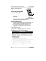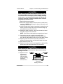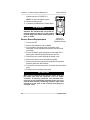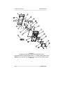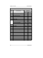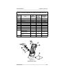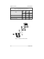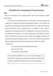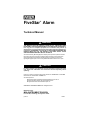
1
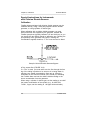
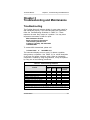
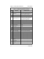
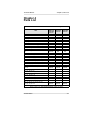
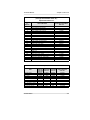
®
FiveStar Alarm
Technical Manual
"
WARNING
THIS MANUAL MUST BE CAREFULLY READ BY ALL INDIVIDUALS WHO
HAVE OR WILL HAVE THE RESPONSIBILITY FOR SERVICING THE PRODUCT.
Like any piece of complex equipment, this instrument will perform as
designed only if it is used and serviced in accordance with the manufacturer’s
instructions. OTHERWISE IT COULD FAIL TO PERFORM AS DESIGNED AND
PERSONS WHO RELY ON THIS PRODUCT FOR THEIR SAFETY COULD
SUSTAIN SEVERE PERSONAL INJURY OR DEATH.
The warranties made by Mine Safety Appliances Company with respect to the product are voided if
the product is not used and serviced in accordance with the instructions in this manual. Please
protect yourself and others by following them. We encourage our customers to write or call
regarding this equipment prior to use or for any additional information relative to use or repairs.
"
CAUTION
For safety reasons, this equipment must be operated by qualified personnel
only. Read and understand the instruction manual completely before
operating.
In the U.S., to contact your nearest stocking location, dial toll-free 1-800-MSA-2222. To contact MSA
International, dial 1-412-967-3000 or 1-800-MSA-7777.
This manual pertains to:
North American approved instruments with Serial Number prefix "F" and "G"
Australian approved instruments with Serial Number prefix "A"
EN approved instruments with Serial Number prefix "A".
© MINE SAFETY APPLIANCES COMPANY 2005 - All Rights Reserved
Manufactured by
MSA INSTRUMENT DIVISION
P.O. Box 427, Pittsburgh, Pennsylvania 15230
(L) Rev 9
710440
MSA Portable Instrument Warranty
1.
WarrantyITEM
WARRANTY PERIOD
Chassis and electronics
Lifetime (MSA will support product
for five years after production ends)
All sensors, unless otherwise specified
Two years
Pump and drive unit
Two years
Rechargeable batteries
Two years
This warranty does not cover filters, fuses, etc. Certain other accessories
not specifically listed here may have different warranty periods. This
warranty is valid only if the product is maintained and used in accordance
with Seller’s instructions and/or recommendations. The Seller shall be
released from all obligations under this warranty in the event repairs or
modifications are made by persons other than its own or authorized
service personnel or if the warranty claim results from physical abuse or
misuse of the product. No agent, employee or representative of the
Seller has any authority to bind the Seller to any affirmation,
representation or warranty concerning this product. Seller makes no
warranty concerning components or accessories not manufactured by
the Seller, but will pass on to the Purchaser all warranties of
manufacturers of such components. THIS WARRANTY IS IN LIEU OF
ALL OTHER WARRANTIES, EXPRESSED, IMPLIED OR
STATUTORY, AND IS STRICTLY LIMITED TO THE TERMS
HEREOF. SELLER SPECIFICALLY DISCLAIMS ANY WARRANTY
OF MERCHANTABILITY OR OF FITNESS FOR A PARTICULAR
PURPOSE.
2.
Exclusive Remedy- It is expressly agreed that Purchaser’s sole and
exclusive remedy for breach of the above warranty, for any tortious
conduct of Seller, or for any other cause of action, shall be the repair
and/or replacement at Seller’s option, of any equipment or parts
thereof, which after examination by Seller is proven to be defective.
Replacement equipment and/or parts will be provided at no cost to
Purchaser, F.O.B. Seller’s Plant. Failure of Seller to successfully
repair any nonconforming product shall not cause the remedy
established hereby to fail of its essential purpose.
3.
Exclusion of Consequential Damages- Purchaser specifically
understands and agrees that under no circumstances will seller be
liable to purchaser for economic, special, incidental or consequential
damages or losses of any kind whatsoever, including but not limited
to, loss of anticipated profits and any other loss caused by reason of
nonoperation of the goods. This exclusion is applicable to claims for
breach of warranty, tortious conduct or any other cause of action
against seller.
Technical Manual
Table of Contents
Table of Contents
Chapter 1
Set-up and Configuration. . . . . . . . . . . . . . . . . . . . . . . . . 1-1
Sensor Autoconfiguration and Replacement . . . . . . . . . . . . . 1-2
"CAUTION . . . . . . . . . . . . . . . . . . . . . . . . . . . . . . . . . . . . 1-3
Replacing a Sensor . . . . . . . . . . . . . . . . . . . . . . . . . . . . . 1-3
Figure 1-1. Sensor Replacement . . . . . . . . . . . . . . . . . . . . . . . . . 1-3
"CAUTION . . . . . . . . . . . . . . . . . . . . . . . . . . . . . . . . . . . .
"WARNING . . . . . . . . . . . . . . . . . . . . . . . . . . . . . . . . . . .
Installing a New Type of Sensor. . . . . . . . . . . . . . . . . . .
Table 1-1. Allowable Sensor Installation Locations. .
1-4
1-4
1-4
1-5
Figure 1-2. Sensor and Zebra Strip Locations in Sensor Cavity 1-5
"WARNING . . . . . . . . . . . . . . . . . . . . . . . . . . . . . . . . . . . 1-6
"CAUTION . . . . . . . . . . . . . . . . . . . . . . . . . . . . . . . . . . . . 1-6
Figure 1-3. Removing the Jumper . . . . . . . . . . . . . . . . . . . . . . . . 1-6
Removing a Sensor . . . . . . . . . . . . . . . . . . . . . . . . . . . . . 1-7
"CAUTION . . . . . . . . . . . . . . . . . . . . . . . . . . . . . . . . . . . . 1-7
Sensor Autoconfiguration . . . . . . . . . . . . . . . . . . . . . . . . . 1-8
Figure 1-4. New Sensor Setup. . . . . . . . . . . . . . . . . . . . . . . . . . . 1-8
Figure 1-5. Sensor Update? Yes/No . . . . . . . . . . . . . . . . . . . . . 1-8
Figure 1-6. Please Wait . . . . . . . . . . . . . . . . . . . . . . . . . . . . . . . . 1-8
Figure 1-7. Units Measured . . . . . . . . . . . . . . . . . . . . . . . . . . . . . 1-8
Figure 1-8. Gases Measured . . . . . . . . . . . . . . . . . . . . . . . . . . . . 1-9
Figure 1-9. Sample Combustible Alarm Setpoints. . . . . . . . . . . . 1-9
Figure 1-10. Sample O2 Alarm Setpoints . . . . . . . . . . . . . . . . . . 1-9
Figure 1-11. Sample Toxic Alarm Setpoints . . . . . . . . . . . . . . . . 1-9
Table 1-2. Default Factory Alarm Setpoints. . . . . . 1-10
FiveStar Alarm
TOC-1
Table of Contents
Technical Manual
Figure 1-12. Accept Alarms Reset/Show/OK . . . . . . . . . . . . . . . 1-10
"CAUTION . . . . . . . . . . . . . . . . . . . . . . . . . . . . . . . . . . . 1-11
Figure 1-13. Check Sensor Cover/ Label Empty Slots / Quit - OK 1-11
Manual Sensor Configuration. . . . . . . . . . . . . . . . . . . . . 1-12
To Enter the Sensor Setup Mode Manually . . . . . . . . . 1-12
Chapter 2
Calibration . . . . . . . . . . . . . . . . . . . . . . . . . . . . . . . . . . . . . 2-1
Optional Fresh Air Setup . . . . . . . . . . . . . . . . . . . . . . . . . . . .
Activating the Fresh Air Setup Option. . . . . . . . . . . . . . .
To Cancel Fresh Air Setup . . . . . . . . . . . . . . . . . . . . . . .
Figure 2-1. Fresh Air Setup? . . . . . . . . . . . . . . . . . . .
To Perform Fresh Air Setup . . . . . . . . . . . . . . . . . . . . . .
Calibration Adjustment . . . . . . . . . . . . . . . . . . . . . . . . . . . . . .
Preparing to Calibrate . . . . . . . . . . . . . . . . . . . . . . . . . . .
" WARNING. . . . . . . . . . . . . . . . . . . . . . . . . . . . . . . . . . .
Calibration Procedures . . . . . . . . . . . . . . . . . . . . . . . . . . . . . .
Figure 2-2. Calibration - No/Yes? . . . . . . . . . . . . . . .
Figure 2-3. Apply Fresh Air. . . . . . . . . . . . . . . . . . . .
Figure 2-4. Adjusting Zeroes. . . . . . . . . . . . . . . . . . .
Figure 2-5. Combustible Gas Calibration Display . . .
Figure 2-6. Calibration Cap Installation . . . . . . . . . . .
Figure 2-7. Snap Calibration Cap Installation . . . . . .
Oxygen Sensor Calibration Check. . . . . . . . . . . . . . . . . .
Figure 2-8. Combustible Gas Span Adjustment. . . .
Toxic Gas Sensor Calibration . . . . . . . . . . . . . . . . . . . . .
To repeat calibration procedure: . . . . . . . . . . . . . . . . . .
To end calibration procedure: . . . . . . . . . . . . . . . . . . . . .
Figure 2-9. Remove Cal Cap . . . . . . . . . . . . . . . . . .
Figure 2-10. Saving Calibration
Please Wait . . . . . . . . . . . . . . . . . . . . . . . . . . . . . . . . .
Figure 2-11. Power OFF . . . . . . . . . . . . . . . . . . . . . . .
Special Instructions for Instruments
with Chlorine Dioxide Sensors . . . . . . . . . . . . . . . . . . . . .
Calibration . . . . . . . . . . . . . . . . . . . . . . . . . . . . . . . . . . . . .
Figure 2-12. Setup for Chlorine Dioxide Generator
Bypass . . . . . . . . . . . . . . . . . . . . . . . . . . . . . . . . . . . . .
TOC-2
2-1
2-1
2-1
2-1
2-2
2-2
2-2
2-2
2-3
2-3
2-3
2-4
2-4
2-5
2-5
2-6
2-6
2-7
2-7
2-7
2-7
2-7
2-7
2-8
2-8
2-8
FiveStar Alarm
Technical Manual
Table of Contents
Chapter 3
Troubleshooting and Maintenance . . . . . . . . . . . . . . . . . 3-1
Troubleshooting. . . . . . . . . . . . . . . . . . . . . . . . . . . . . . . . . . . . 3-1
Table 3-1. Troubleshooting Guidelines . . . . . . . . . . . 3-1
Repair Procedures . . . . . . . . . . . . . . . . . . . . . . . . . . . . . . . . . 3-4
Battery Pack Replacement . . . . . . . . . . . . . . . . . . . . . . . 3-4
Remove the Battery Pack . . . . . . . . . . . . . . . . . . . . . . . . 3-4
Replace the Battery Pack . . . . . . . . . . . . . . . . . . . . . . . . 3-4
Sensor Replacement . . . . . . . . . . . . . . . . . . . . . . . . . . . . 3-4
Main Electronics Board Replacement . . . . . . . . . . . . . . . 3-4
" CAUTION. . . . . . . . . . . . . . . . . . . . . . . . . . . . . . . . . . . 3-4
Figure 3-1. Battery Pack Removal. . . . . . . . . . . . . . . 3-4
" CAUTION. . . . . . . . . . . . . . . . . . . . . . . . . . . . . . . . . . . 3-5
" CAUTION. . . . . . . . . . . . . . . . . . . . . . . . . . . . . . . . . . . 3-5
Figure 3-2. Display Connector . . . . . . . . . . . . . . . . . . 3-5
" WARNING . . . . . . . . . . . . . . . . . . . . . . . . . . . . . . . . . . 3-6
Sensor Board Replacement. . . . . . . . . . . . . . . . . . . . . . . 3-6
" CAUTION. . . . . . . . . . . . . . . . . . . . . . . . . . . . . . . . . . . 3-6
Figure 3-3. Sequence for Tightening Screws . . . . . . 3-6
" WARNING . . . . . . . . . . . . . . . . . . . . . . . . . . . . . . . . . . 3-7
Display Module Replacement. . . . . . . . . . . . . . . . . . . . . 3-7
" CAUTION. . . . . . . . . . . . . . . . . . . . . . . . . . . . . . . . . . . 3-8
" CAUTION. . . . . . . . . . . . . . . . . . . . . . . . . . . . . . . . . . . 3-9
Figure 3-4. Keypad Ribbon Cable Replacement. . . . 3-9
" WARNING . . . . . . . . . . . . . . . . . . . . . . . . . . . . . . . . . 3-10
Chapter 4
Parts List . . . . . . . . . . . . . . . . . . . . . . . . . . . . . . . . . . . . . . 4-1
Table 4-1. North American/Australian Common
Accessory Parts List . . . . . . . . . . . . . . . . . . . . . . . . . .
Figure 4-1. North American
(through Serial Number Prefix "E")
Replacement Parts . . . . . . . . . . . . . . . . . . . . . . . . . . .
Table 4-2. North American
(through Serial Number Prefix "E")
Replacement Parts List . . . . . . . . . . . . . . . . . . . . . . .
Table 4-3. Replacement Sensors. . . . . . . . . . . . . . . .
FiveStar Alarm
4-1
4-2
4-3
4-3
TOC-3
Table of Contents
Technical Manual
Figure 4-2. Australian and European Approved
Replacement Parts and North American
(Serial Number Prefix "F" or Higher)
Replacement Parts . . . . . . . . . . . . . . . . . . . . . . . . . . .
Table 4-4. North American
(Serial Number Prefix "F" or "G")
Replacement Parts List . . . . . . . . . . . . . . . . . . . . . . . .
Table 4-5. Australian/European Replacement Parts List.
Table 4-6. Pump and Aspirator Assembly
Replacement Parts List . . . . . . . . . . . . . . . . . . . . . . . .
Figure 4-3. Replacement Parts. . . . . . . . . . . . . . . . . .
Figure 4-4. Battery and Fuse Location . . . . . . . . . . .
Table 4-7. Replaceable Battery Pack Parts List . . . .
TOC-4
4-4
4-5
4-6
4-7
4-7
4-8
4-8
FiveStar Alarm
Technical Manual
Chapter 1, Setup and Configuration
Chapter 1
Set-up and Configuration
The user must be familiar with the procedures in the FiveStar
Alarm Instruction Manual, including all cautions and warnings.
The FiveStar Alarm can be configured in many ways to meet
your changing gas detection needs. There are four means for
making instrument configuration changes (the first two are
described in the instruction manual, the third is described in this
chapter, and the fourth is accessible only with FiveStar LINK):
1. At instrument turn-ON,
the following setup option is available:
• Fresh Air Setup (if enabled).
2. When attaching the battery to the instrument,
the following setup options are available:
• Language for displays (if enabled)
• Operating Beep
• Peak / STEL / TWA displays (all/none)
• Set time and date
• Sensor configuration.
3. During Sensor setup or sensor autoconfiguration,
the following setup options are available:
• LEL versus CH4 combustible display
• Gas sensors installed
• Reset alarm settings to factory defaults.
4. FiveStar Link is a separately-supplied software package for
communicating to the FiveStar instrument with a personal
computer. To operate, FiveStar Link requires a set of
software and an Infrared adapter. These components may
be purchased together (as P/N 710988) or separately.
With FiveStar Link software, the following options can be reset:
FiveStar Alarm
1-1
Chapter 1, Setup and Configuration
Technical Manual
• Eight-character instrument "name" shown on
instrument startup (default is "PASSPORT")
• Change alarm setpoints
• Set backlight time-out (1 minute to 20 minutes)
• Operating beep
• Individually turn ON/OFF Peak, STEL
and/or TWA pages
• Disable Fresh Air Setup (available only in
instruments with software V1.2 or higher)
• Set Time and Date (available only in instruments
with software V1.2 or higher)
• Disable Autoconfigure (available only in instruments
with software V1.2 or higher)
• Enable or disable Data Tagging
(software V2.0 or higher)
• Enable or disable the "display alarms" on start-up
option (software V2.01 or higher)
• Enable or disable the multilingual function
(English/Spanish/Canadian French
software V2.01 or higher)
• Disable Autocalibration capability
(software V3.0 or higher)
• Change Periodic Datalog intervals
(software V3.0 or higher).
Sensor Autoconfiguration
and Replacement
When a sensor is replaced, when a new type of sensor is
installed or when a sensor is removed, the FiveStar Alarm steps
the user through an "autoconfiguration" program. All instruments
leave the factory with the autoconfigure feature enabled. The
FiveStar Link program may be used to disable this feature if the
user desires.
1-2
FiveStar Alarm
Technical Manual
Chapter 1, Setup and Configuration
The autoconfiguration feature allows the user to change the
instrument sensor configuration as the user’s gas sensing needs
change. The unit steps through the autoconfiguration sequence
(listed later in this chapter) when the instrument recognizes that:
• a new serial number sensor is installed (a replacement)
• a sensor is removed
• a new type of gas sensor is added.
" CAUTION
When removing or installing the combustible gas sensor,
remove the battery pack. Otherwise, the sensor pins may
short to the case and cause an "ERROR 5" message (damage
to the combustible sensor circuit).
Replacing a Sensor
To replace a sensor in your FiveStar Alarm:
1.
2.
3.
4.
Verify that instrument is OFF; remove the battery pack.
Remove sensor cover screws and cover.
Gently lift out and properly dispose of sensor to be replaced.
Inspect the condition of electrical contact "Zebra Strip" located
below the sensor.
• The "Zebra Strip" is a small, black conductive elastomer
which makes contact to the sensor memory chip on the
bottom of the sensors (see Chapter 4, FIGURE 4-1).
• If this is not in place or is not making good contact,
the instrument will not properly recognize the
installed sensors.
5. If the Zebra Strip is damaged or missing,
replace it with a new Zebra Strip (P/N
655188) before installing new sensor.
6. If replacement sensor is equipped with a
shorting plate, clip or wire attached to
its pins, remove plate, clip or wire
before inserting the replacement
sensor.
7. Carefully align the new sensor contact
pins with the sockets on the Sensor
Figure 1-1.
Board.
Sensor Replacement
FiveStar Alarm
1-3
Chapter 1, Setup and Configuration
Technical Manual
8. Press the new sensor into place.
9. Replace the sensor gasket and sensor cover.
10. Re-install screws to hold down the sensor cover.
" CAUTION
Do not operate the instrument without the sensor cover
fully installed. The zebra strips require pressure to enable
proper contact. Without proper contact, data may be written
improperly to the sensor memory and the data may become
corrupted, rendering the sensor unusable.
NOTE: NO, Cl2, ClO2, and NH3 sensors are "biased"
sensors. As such, they require approximately 12
hours once installed (with battery pack attached, but
turned OFF) for the output to stabilize. Allow the unit
to stabilize before calibrating and using in the field.
11. Replace cover before turning instrument back ON to
verify configuration.
• The sensor cover holds the sensors down firmly against
the Zebra Strips to ensure proper electrical contact.
12. Turn the instrument ON and proceed through sensor setup.
• The instrument proceeds to a sensor update mode similar
to that for adding or deleting a sensor. See "Sensor
Autoconfiguration" later in this chapter for instructions.
• If instrument autoconfiguration is disabled, the instrument
shows an error message. See "Manual Sensor
Configuration" later in this chapter for instructions on
manual configuration.
" WARNING
Verification of calibration response is required; otherwise the
instrument will not perform as required and persons who rely
on this product for their safety could sustain serious personal
injury or death.
Installing a New Type of Sensor
1. Verify that unit is OFF.
2. Remove battery.
3. Remove sensor cover screws and sensor cover (FIGURE 1-2).
1-4
FiveStar Alarm
Technical Manual
Chapter 1, Setup and Configuration
4. Verify that the electrical
contact Zebra Strip
below sensor is not
missing or damaged.
• The Zebra Strip is a
small, black
conductive elastomer
which makes contact
to the sensor memory
chip on the bottom of
the sensors
(FIGURE 4-1).
• If Zebra Strip is not in
place or making good
contact, the unit will
not properly
recognize the installed
sensors.
• If the Zebra Strip is
damaged or missing,
replace it with a new
Zebra Strip
(P/N 655188) before
installing the sensor.
Figure 1-2. Sensor and Zebra Strip
Locations in Sensor Cavity
5. Install new sensor in appropriate location noted in TABLE 1-1.
Table 1-1. Allowable Sensor Installation Locations
SENSOR TYPE
BIASED
Combustible
Oxygen
Carbon Monoxide
Hydrogen Sulfide
YES -
Nitric Oxide
Nitrogen Dioxide
Sulfur Dioxide
Phosphine
Ammonia
Chlorine
Chlorine Dioxide
NOTE:
YES YES YES -
NO
NO
NO
NO
SEE
NO
NO
NO
SEE
SEE
SEE
ALLOWABLE POSITIONS
Comb. ONLY
O2 ONLY
Tox 1, 2, 3
Tox 1, 2, 3
NOTE
Tox 3 ONLY
Tox 1, 2, 3
Tox 1, 2, 3
Tox 1, 2, 3
NOTE
NOTE
NOTE
Tox 3 ONLY
Tox 3 ONLY
Tox 3 ONLY
Biased sensors must be factory installed in units with
Serial No. Prefixes of "F" or lower. For units with
FiveStar Alarm
1-5
Chapter 1, Setup and Configuration
Technical Manual
Figure 1-3.
Removing the Jumper
Serial No. Prefixes of "G" or higher, be sure to
remove the jumper pin from the Tox 3 position (See
FIGURE 1-3) before installing sensor.
" WARNING
Be sure to remove the sensor cover label covering the new
location if there was no sensor in that position before. Failure
to remove this label prevents the sensor from detecting
gases which may result in serious personal injury or death.
6. Carefully align the contact pins of the new sensor with the
Sensor Board sockets; press the new sensor into place.
7. Replace the sensor gasket and sensor cover.
8. Re-install screws to hold down sensor cover.
" CAUTION
Do not operate instrument without the sensor cover fully
installed. The zebra strips require pressure to enable proper
contact. Without proper contact, data may be improperly written
to the sensor memory and data may become corrupted,
rendering the sensor unusable.
• The sensor cover holds the sensors down firmly against
the Zebra Strips to ensure proper electrical contact.
1-6
FiveStar Alarm
Technical Manual
Chapter 1, Setup and Configuration
9. Install battery pack. Instrument will turn ON. Proceed through
sensor setup.
NOTE: NO, Cl2, and NH3 sensors are "biased" sensors. As
such, they require approximately 12 hours once
installed (with battery pack attached, but turned
OFF) for the output to stabilize. Allow the unit to
stabilize before calibrating and using in the field.
• When turned ON, the instrument now proceeds to a
sensor update mode similar to that for adding or deleting a
sensor. See "Sensor Autoconfiguration" later in this
Chapter for instructions.
• If the instrument autoconfiguration is disabled, the
instrument shows an error message. Refer to "Manual
Sensor Configuration" later in this chapter for instructions
on how to enter the configuration manually.
Removing a Sensor
To remove a sensor from the instrument:
1. Verify that the instrument is turned OFF.
2. Remove battery pack.
3. Remove the sensor cover screws and sensor cover.
4. Gently lift out the sensor that is no longer required.
5. Place the "Missing Sensor" label (P/N 710478) on the
underside of the sensor cover for the position where the
sensor was removed.
" CAUTION
Failure to install the "Missing Sensor" label exposes the sensor
cavity to dirt and water, may lead to instrument damage and
can also increase instrument response and clear times when
operated in pumped mode.
6. Replace sensor gasket and sensor cover.
7. Re-install the screws to hold down the sensor cover.
• The cover should be in place before turning the instrument
back ON to verify configuration.
• The sensor cover holds the sensors down firmly against
the Zebra Strips to ensure proper electrical contact.
8. Install battery pack.
FiveStar Alarm
1-7
Chapter 1, Setup and Configuration
Technical Manual
9. Turn the instrument ON and proceed through sensor setup.
• If the instrument autoconfiguration is disabled, the
instrument shows an error
message. Refer to "Manual
Sensor Configuration" later in
this chapter for instructions on
how to enter the configuration
manually.
Sensor Autoconfiguration
If the Sensor autoconfiguration is
enabled, the following occurs after
replacing a sensor, installing a new
type of sensor or removing a sensor;
the instrument:
• automatically enters configuration
mode when turned ON
• proceeds through the following
sequence to verify and store the new
configuration into instrument memory:
Figure 1-4.
New Sensor Setup
Figure 1-5.
Sensor Update? Yes/No
Turn the instrument ON by pressing the
ON/OFF button:
• Instrument display flashes the
"welcome" screen; FIGURE 1-4
appears on the display.
• Screen changes to FIGURE 1-5.
• Pressing the skip PAGE (SKIP) button
exits the autoconfiguration sequence.
• Instrument displays an error message;
an alarm sounds.
Figure 1-6.
Please Wait
• Instrument must be turned OFF to
silence the alarm.
• Pressing the RESET (YES) button
causes instrument to re-read
sensor memories.
• FIGURE 1-6 screen appears.
• Instrument now allows user to select
format for the combustible display.
1-8
Figure 1-7.
Units Measured
FiveStar Alarm
Technical Manual
Chapter 1, Setup and Configuration
• Pressing PAGE (LEL) button causes
the combustible readings to display
as 0-100% LEL.
• Pressing the RESET (YES) button
causes the instrument to display
combustible readings as direct
0-5% Methane.
• Instrument stores this data and
reads the remainder of the sensor
memory chips "Please Wait" displays.
• Screen then flashes the units of
gases measured (FIGURE 1-7).
• Display flashes the sensors that the
instrument recognizes (FIGURE 1-8).
• Instrument displays alarm setpoints
for the installed sensors.
• The screen automatically scrolls from
gas to gas in five-second intervals
(FIGURES 1-8 through 1-10).
• To hold an alarm setpoint reading for
more than five seconds, press and
hold the RESET button.
• To continue, release RESET button.
• To skip through alarm displays faster,
press the PAGE button.
• The instrument then asks user to
verify that alarm setpoints are
acceptable (FIGURE 1-12).
• Pressing the PAGE (RESET) button
causes the instrument to restore the
default alarm values stored in the
sensor memories.
• After resetting the alarm
setpoints, the instrument again
scrolls through the alarms
pages.
• Once the alarm setpoints are
reset, the "Accept Alarms"
screen no longer reappears.
FiveStar Alarm
Figure 1-8.
Gases Measured
Figure 1-9. Sample
Combustible Alarm
Setpoints
Figure 1-10. Sample
O2 Alarm Setpoints
Figure 1-11.
Sample Toxic Alarm
Setpoints
1-9
Chapter 1, Setup and Configuration
Technical Manual
Figure 1-12. Accept Alarms
Reset/Show/OK
Table 1-2. Default Factory Alarm Setpoints
SENSOR TYPE
COMBUSTIBLE
OXYGEN
CARBON MONOXIDE
HYDROGEN SULFIDE
NITRIC OXIDE
NITROGEN DIOXIDE
SULFUR DIOXIDE
PHOSPHINE
AMMONIA
CHLORINE
CHLORINE DIOXIDE
EXPOSURE
WARN
LOW ALARM
HIGH ALARM
LEL - N/A
0.5% CH4
10% LEL or
1.0% CH4
60% LEL or
3.0 CH4
DEFICIENCY
ENRICHMENT
19.5
22.0
LOW ALARM
HIGH ALARM
STEL
TWA
35
10
25
5
5
-
1200
100
100
20
90
0.3
25
2.0
0.5
400
15
25
5
5
1
35
1.0
0.3
35
10
25
2
2
0.3
25
0.5
0.1
• Pressing the ON/OFF (SHOW) button allows the user to scroll
through the "Show Alarm Setpoints" screens again.
• Pressing the RESET (OK) button accepts the alarm setpoints.
• The instrument now returns to the "Sensor Update?"
Query screen.
• Pressing RESET (YES) returns the instrument to the
autoconfiguration sequence above.
• During autoconfiguration, if the instrument did not
recognize a sensor installed in the unit, recheck the
sensor Zebra Strip condition. Also ensure that the sensor
cover is screwed down tight to obtain a solid contact
between the sensor memory board and the sensor board.
1-10
FiveStar Alarm
Technical Manual
Chapter 1, Setup and Configuration
Figure 1-13. Check Sensor Cover/
Label Empty Slots / Quit - OK
• Pressing PAGE (SKIP) exits the autoconfigure sequence.
• The instrument displays the FIGURE 1-13 screen to remind the
user to:
• check the sensor cover to ensure that "missing sensor"
labels (P/N 710478) cover slots where sensors are
not installed
• verify there are no "sensor missing" labels over any
position where a sensor is installed.
" CAUTION
Failure to install the "Missing Sensor" label exposes the sensor
cavity to dirt and water and may lead to instrument damage.
This can also increase instrument response and clear times
when operated in pumped modes.
• Pressing the PAGE (QUIT) button powers down the instrument.
• Pressing the RESET (OK) button sends the unit into the
calibration mode.
• See Chapter 2 for "Calibration Procedure."
NOTE:
Once the instrument has performed the
autoconfiguration procedure, any newly installed
sensor must be calibrated prior to use.
NOTE:
For instruments with software versions lower than 1.2,
all calibration data will be reset to the default values
in the sensor memories; the entire instrument must
be recalibrated.
It is recommended that all sensor calibrations be checked
after autoconfiguration is run and prior to instrument
use.
FiveStar Alarm
1-11
Chapter 1, Setup and Configuration
Technical Manual
Manual Sensor Configuration
For instruments with the autoconfiguration feature disabled, the
sensor setup sequence can be entered manually. A variation of
this sequence must also be used for instruments with software
versions lower than 1.2.
To Enter the Sensor Setup Mode Manually
1. Make sure the instrument is turned OFF.
2. Remove the battery pack.
3. Press and hold the RESET button.
4. Re-install the battery pack while holding the RESET button.
• The instrument enters the Sensor Setup mode.
To enter the setup mode with instruments containing software
versions lower than 1.2:
1.
2.
3.
4.
Make sure the instrument is turned OFF.
Remove the battery pack.
Press and hold the RESET button.
Re-install the battery pack while holding the RESET button.
• The instrument screen turns black.
5. Immediately press and hold the PAGE button until the setup
query page appears.
• The instrument enters the Sensor Setup mode.
1-12
FiveStar Alarm
Technical Manual
Chapter 2, Calibration
Chapter 2
Calibration
Optional Fresh Air Setup
The FiveStar Alarm can be set to allow the user to automatically
zero the measurement systems and calibrate the oxygen system
when the unit is turned ON.
Activating the Fresh Air Setup Option
Configuration of the Fresh Air Setup is done by way of the MSA
LINK program. See instructions in the MSA LINK program
software for this information.
When this feature is activated and the instrument is turned ON,
the FiveStar Alarm completes its self-tests and asks if a Fresh
Air Setup is desired (FIGURE 2-1).
Figure 2-1.
Fresh Air Setup?
To Cancel Fresh Air Setup
• If the PAGE (NO) button is pressed or if no button is pressed
within five seconds, the instrument does not perform a Fresh Air
Setup. Instead, it goes on to operate in the normal measure
mode and displays the Exposure page.
FiveStar Alarm
2-1
Chapter 2, Calibration
Technical Manual
To Perform Fresh Air Setup
Press the RESET (YES) button within five seconds.
• The FiveStar Alarm begins to perform a Fresh Air Setup.
• Oxygen is set at 20.8 percent.
• All other gases are set at zero.
NOTE:
If the Fresh Air Setup feature is activated and an error
message is displayed, press the RESET button to
exit the Fresh Air Setup and enter the Measure
mode. This may occur if the original readings were
outside of the limits for the Fresh Air Setup feature.
This is to protect the user from zeroing out
potentially hazardous gases.
Persons responsible for the use of the FiveStar Alarm must
determine whether or not the Fresh Air Setup option should be
used. The user’s abilities, training, and normal work practices
must be considered when making this decision.
Calibration Adjustment
FiveStar Alarm calibration can be adjusted easily by using gases
of known mixtures and concentrations.
Preparing to Calibrate
Before starting, be certain that the instrument is in normal fresh
air, free of combustible or toxic gases. If the ambient air has
contaminants, use bottled zero air (20.8% oxygen in nitrogen)
when applying fresh air. To prepare to calibrate:
1. Turn OFF the FiveStar Alarm.
2. Allow the instrument to stabilize for several minutes in fresh
air at the temperature and air pressure of intended use.
" WARNING
The FiveStar Alarm does not provide any protection while
the calibration is being adjusted. Do not rely on the
instrument for protection at this time; otherwise, serious
personal injury or death could result.
2-2
FiveStar Alarm
Technical Manual
Chapter 2, Calibration
Calibration Procedures
1. Press the ON/OFF button; immediately and simultaneously
press and hold the PAGE and the RESET buttons.
Figure 2-2.
Calibration - No/Yes?
• An alternative method is to push and hold the PAGE and
the RESET buttons; then, press the ON/OFF button.
• The instrument turns ON (FIGURE 2-2):
To Cancel Calibration:
Press the PAGE (NO) button or wait five seconds.
• The FiveStar Alarm begins warming up and enters the
Exposure display page.
To Continue Calibration:
2. Press the RESET (YES) button.
• Display prompts you for Fresh Air (FIGURE 2-3).
Apply fresh air if this was not done in step 1.
Figure 2-3.
Apply Fresh Air
To Cancel:
Press the PAGE (QUIT) button.
• Instrument beeps and automatically shuts OFF.
FiveStar Alarm
2-3
Chapter 2, Calibration
Technical Manual
To Proceed:
4. Press the RESET (READY) button.
5. Wait approximately 15 seconds for the FiveStar Alarm to
complete the fresh air adjustments.
• During this time, the FIGURE 2-4 display appears.
Figure 2-4.
Adjusting Zeroes
After the fresh air adjustments are made, the FiveStar Alarm is
ready to complete span calibration.
Figure 2-5.
Combustible Gas Calibration Display
• The display appears (FIGURE 2-5):
The user can calibrate the gas sensors in the following order:
•
•
•
•
•
2-4
Combustible Gas
Oxygen
Toxic Gas #1
Toxic Gas #2
Toxic Gas #3
FiveStar Alarm
Technical Manual
Chapter 2, Calibration
Press the PAGE (SKIP)
button to skip calibration
for any gases you do not
want to change.
6. There are three means
to supply gas to the
FiveStar instrument
for calibration:
• Metal Calibration Cap
(P/N 710572):
To attach the Metal
Calibration Cap:
a. Align the screw
heads in the
Cap with the
holes for
the sensor
cover screws
(FIGURE 2-6).
b.
Figure 2-6.
Calibration Cap Installation
Holding the
Calibration Cap
in place, wrap
the strap around
the unit and
through
the strap slot;
pull the strap
snug.
• Plastic Calibration Cap
Figure 2-7.
(P/N 710824):
To attach the Plastic
Snap Calibration Cap Installation
Calibration Cap:
a.
To properly secure the Cap, it is necessary for the
sensor cover to have the snap-on features on the
two sides.
b.
Position the Calibration Cap label "Front" indicator
towards the instrument display and snap the Cap on
the sensor cover (FIGURE 2-7).
FiveStar Alarm
2-5
Chapter 2, Calibration
Technical Manual
• Add-on Pump Module:
To attach the Add-on Pump Module, refer to FiveStar
Instruction Manual (P/N 710436), FIGURE 2-47.
Once the calibration sampling device is attached, apply
calibration gas at 0.25 lpm flow rate.
a. Attach a 0.25-lpm (liters-per-minute) Flow Controller to the
gas tank.
b. Attach calibration tubing to the Five Star calibration
cap inlet.
c. Attach the other end of the calibration tubing to the
0.25-lpm Flow Controller.
d. Turn the knob on the gas tank in a counterclockwise direction.
7. Press the RESET (READY) button.
8. Wait for the readings to stabilize.
NOTE: During calibration, the display reading may appear
more unstable than normal. The display’s digital
filtering has been disabled to provide the most rapid
reading possible.
9. After the display stabilizes,
adjust the display reading to
agree with the known amount
of calibration gas.
a. Push the PAGE (DOWN)
button to lower the reading.
b. Push the RESET (UP)
button to raise the reading.
• Holding either button
causes the reading to
change continuously.
Figure 2-8.
Combustible Gas Span
Adjustment
10. Push the ON/OFF (OK) button to accept the reading.
• The new reading is stored in memory, and the FiveStar
Alarm automatically moves to next reading.
Oxygen Sensor Calibration Check
After the combustible gas calibration is completed, the instrument
automatically moves to the oxygen sensor calibration check. The
zero adjustment previously calibrated the oxygen sensor to
2-6
FiveStar Alarm
Technical Manual
Chapter 2, Calibration
20.8%. Do not adjust the oxygen reading to the cylinder value, as
slight variations may occur; however, verify that the oxygen
reading is within the limits stated on the cylinder. Software
version 2.11 and higher only allows the user to review the
oxygen reading. After verifying that the reading is within the limits
stated on the cylinder, simply press the PAGE (SKIP) button to
continue to the toxic gas calibration.
Toxic Gas Sensor Calibration
After the oxygen calibration check is
completed, the FiveStar Alarm automatically
moves to the toxic gas page. Each toxic gas
calibration can be completed in the same
way as the combustible gas calibration. It
may be necessary to change gas samples to
provide the proper gas.
Figure 2-9.
Remove Cal Cap
• When all of the selected calibrations are
set, a long beep sounds and the display
reads (FIGURE 2-9):
To repeat calibration procedure:
Press the PAGE (NO) button.
To end calibration procedure:
Remove the calibration cap and press the
RESET (YES) button.
• The (FIGURE 2-10)
display appears:
Figure 2-10.
Saving Calibration
Please Wait
• Calibration gases clear from the
sensors (about 30 seconds).
• For instruments with software
versions 1.2 or higher, the
instrument automatically turns
ON and goes into the normal
operation mode.
Figure 2-11.
Power OFF
• For instruments with software versions lower than
1.2, A long beep sounds and the FiveStar Alarm
turns OFF automatically (FIGURE 2-11):
FiveStar Alarm
2-7
Chapter 2, Calibration
Technical Manual
Special Instructions for Instruments
with Chlorine Dioxide Sensors
Calibration
FiveStar Alarms equipped with chlorine dioxide sensors may be
calibrated directly, using s third party-supplied chlorine dioxide
generator, or using cylinders of chlorine gas.
When calibrating with a chlorine dioxide generator you must
either ensure the flow supplied by the generator exceeds the
FiveStar pump draw (typically between 0.25 and 0.40 lpm) or you
can supply the gas directly through a calibration cap. Hooking the
pump directly to the generator may result in altering the
concentration supplied; therefore, a "Tee" must be used to bleed
Figure 2-12.
Setup for Chlorine Dioxide Generator Bypass
off the excess flow (FIGURE 2-12).
If a "Tee" is used, you must make sure the flow through the free
leg of the tubing is positive to be sure no air is being drawn in,
reducing your sample concentration. Once set up, follow the
instructions in the Technical manual (P/N 710440) for calibrating
the FiveStar Alarm and set the chlorine dioxide reading to the
known concentration from the generator.
When using a cylinder of chlorine gas, set the reading to one-half
the known concentration of the cylinder (e.g., for MSA P/N
710331, 2 ppm, set the reading to 1.00 ppm chlorine dioxide).
2-8
FiveStar Alarm
Technical Manual
Chapter 3, Troubleshooting and Maintenance
Chapter 3
Troubleshooting and Maintenance
Troubleshooting
The FiveStar Alarm will operate reliably for years when cared for
and maintained properly. If the instrument becomes inoperative,
follow the Troubleshooting Guidelines in TABLE 3-1. These
represent the most likely causes of a problem. You may return
inoperative instruments to MSA for repair.
MSA Instrument Division
Repair and Service Department
1000 Cranberry Woods Drive
Cranberry Township, PA 16066-5207
1-800-MSA-INST
To contact MSA International, please call:
1-412-967-3000
or
1-800-MSA-7777
The instrument displays an error code if it detects a problem
during startup or operation. See TABLE 3-1 for a brief description
of the error and proper corrective action. When an inoperative
component is located by using the guidelines, it may be replaced
by using one of the following procedures:
Table 3-1. Troubleshooting Guidelines
REPLACE
PROBLEM
MAIN
BATTERY DISPLAY
PACK* MODULE SENSOR ELECTRONICS
MODULE
Does not turn ON
√
√
Does not complete Self-Tests
√
Display segments missing or stuck
√
"ERROR" message after battery installation
√
"ERROR" message during use
√
Battery pack does not hold charge
√
Combustible sensor does not calibrate
√
Oxygen sensor does not calibrate
√
Toxic sensor does not calibrate
√
Clock not holding time.
√
*
Recharge or replace the cells before replacing battery pack.
In all of the above cases and for any other problems, you may return the FiveStar Alarm to
MSA for repairs.
FiveStar Alarm
3-1
Chapter 3, Troubleshooting and Maintenance
Technical Manual
Table 3-1. Troubleshooting Guidelines (continued)
ERROR
CODE
DESCRIPTION
CORRECTIVE ACTION
1
Sensor board error
Check/replace sensor board
2
EEPROM error
Reinitialize the instrument (follow procedure for
manual sensor configuration and answer yes
to query to reinitialize the EEPROM)
3
Pressure sensor error
Replace the main board
4
unused
Check/replace combustible sensor; if this does
not clear the error, replace the sensor board
5
Combustible sensor error
6
Oxygen Sensor error
Check/Replace the oxygen sensor
7
Combustible sensor zero error
Check/replace the combustible sensor
8
Cannot write EEPROM
Check/replace the main board
9
Battery type failure
Replace battery pack
10
No sensors detected
Check to see if sensors and Zebra strips are
in place
11
Multiple sensors removed
from instrument
Check to see if sensors and Zebra strips are
in place
12
Combustible sensor missing
Check combustible sensor and zebra strip
13
Oxygen sensor missing
Check Oxygen sensor and zebra strip
14
Toxic 1 sensor missing
Check Toxic 1 sensor and zebra strip
15
Toxic 2 sensor missing
Check Toxic 2 sensor and zebra strip
16
Toxic 3 sensor missing
Check Toxic 3 sensor and zebra strip
17
Multiple new sensors detected
Run through sensor configuration
18
New combustible sensor installed
Run through sensor configuration
19
New oxygen sensor installed
Run through sensor configuration
20
New Toxic 1 sensor installed
Run through sensor configuration
21
New Toxic 2 sensor installed
Run through sensor configuration
22
New Toxic 3 sensor installed
Run through sensor configuration
23
Multiple sensors installed in
illegal sites
Check sensor placement against TABLE 1-1
24
Improper sensor installed in
combustible site
Check sensor placement against TABLE 1-1
25
improper sensor installed in
oxygen site
Check sensor placement against TABLE 1-1
26
Improper sensor installed in
Toxic 1
Check sensor placement against TABLE 1-1
3-2
(In an Australian approved instrument,
check the fuse on the main board if replacing
the sensor does not clear the error.)
FiveStar Alarm
Technical Manual
Chapter 3, Troubleshooting and Maintenance
Table 3-1. Troubleshooting Guidelines (continued)
ERROR
CODE
DESCRIPTION
CORRECTIVE ACTION
27
Improper sensor installed in
Toxic 2 site
Check sensor placement against TABLE 1-1
28
Improper sensor installed in
Toxic 3 site
Check sensor placement against TABLE 1-1
29
Biased sensor installed in illegal
site
Check sensor placement against TABLE 1-1
30
Multiple sensor memories
corrupted
Check and replace sensors one at a time to
isolate failed sensors
31
Combustible sensor memory
corrupt
Replace Combustible sensor
32
Oxygen sensor memory corrupt
Replace Oxygen sensor
33
Toxic 1 sensor memory corrupt
Replace Toxic 1 sensor
34
Toxic 2 sensor memory corrupt
Replace Toxic 2 sensor
35
Toxic 3 sensor memory corrupt
Replace Toxic 3 sensor
36
Multiple sensor memories
incompatible with instrument
software
Check and replace sensors one at a time to
isolate incorrect sensors
37
Combustible sensor memory
incompatible with instrument
memory
Replace Combustible sensor
38
Oxygen sensor memory
incompatible with instrument
memory
Replace Oxygen sensor
39
Toxic 1 sensor memory
incompatible with instrument
memory
Replace Toxic 1 sensor
40
Toxic 2 sensor memory
incompatible with instrument
memory
Replace Toxic 2 sensor
41
Toxic 3 sensor memory
incompatible with instrument
memory
Replace Toxic 3 sensor
99
Battery Error
Check battery on another instrument; replace
battery if the error follows the battery;
otherwise, replace the main board
For messages 11 to 22, instruments with software version 1.2 or higher will enter the
autoconfiguration mode directly at turn-ON, if autoconfiguration is enabled. If
autoconfiguration is disabled or your instrument software is earlier than version 1.2, the user
must run through the key sequence on battery attachment given in Chapter 1, "Manual
Sensor Configuration."
FiveStar Alarm
3-3
Chapter 3, Troubleshooting and Maintenance
Technical Manual
Repair Procedures
Battery Pack Replacement
Remove the Battery Pack
1. Turn battery mounting screw on the
back of the instrument in a
counterclockwise direction until screw
turns freely.
Figure 3-1.
2. Pull out the battery pack by gripping it Battery Pack Removal
at the edge of the battery pack case
and pulling it away from the unit (FIGURE 3-1).
Replace the Battery Pack
3. Insert the front of the battery pack under the lip on the case
and snap the bottom of the battery pack into the case.
4. Turn the battery mounting screw on the back of the
instrument in a clockwise direction until screw is tight.
Sensor Replacement
See Chapter 1, "Replacing a Sensor" for instructions.
Main Electronics Board Replacement
" CAUTION
Before handling the PC boards, ensure you are properly
grounded; otherwise, static charges from your body could
damage the electronics. Such damage is not covered by
the warranty. Grounding straps and kits are available from
electronics suppliers.
1. Turn power OFF.
2. Remove the Calibration Cap, if installed.
3. Turn the battery mounting screw on the back of instrument in
a counterclockwise direction until screw turns freely.
4. Pull out the battery pack by gripping it at the edge of the
battery pack case and pulling it away from the unit.
5. Remove the six case mounting screws from back of the case.
6. Carefully remove the back of the case.
3-4
FiveStar Alarm
Technical Manual
Chapter 3, Troubleshooting and Maintenance
" CAUTION
When removing the back of the case, be careful not to pull
the buzzer wire from the connector. This is a fragile connector;
use minimum force necessary to prevent breakage; breakage
of this wire is not covered under warranty. If removing the
connector, place a flat screwdriver at the back of the connector
and gently pry connector loose.
7. Remove the buzzer connector.
8. Disconnect the white ribbon connector from the main board
socket by CAREFULLY lifting up the brown locking tabs until
they stop (FIGURE 3-2).
9. Locate the edge of the main pc board that is furthest from the
display; grasp this edge and gently lift the board straight up
and away from the unit until it is free.
10. Holding the white connector, gently rock the main pc board
and pull it away from the connector.
NOTE: Retain foam rubber gasket accompanying pc board.
11. Connect the new main pc board to the white ribbon
connector by gently rocking the pc board into place; latch
down the two tabs located on either side of the ribbon socket.
12. Replace gasket and insert the new main pc board into
position; gently press down until the board snaps into place.
13. Reconnect the buzzer wire.
14. Replace the main pc board, ensuring gasket is appropriately
placed around the entire perimeter of the instrument.
" CAUTION
When replacing the back of the case, tuck the buzzer wire
between the display board and the main board to prevent
damage to the wire.
15. Replace back of
the case and
tighten the six
case-mounting
screws securing
the back of
the case in the
Figure 3-2.
Display Connector
FiveStar Alarm
3-5
Chapter 3, Troubleshooting and Maintenance
Technical Manual
sequence shown in FIGURE 3-3.
NOTE: Do not over-tighten screws.
16. Reconnect battery pack.
17. Completely recalibrate the FiveStar Alarm.
" WARNING
Verification of calibration response is required;
otherwise, the instrument will not perform as
required and persons who rely on this product
for their safety could sustain serious personal
injury or death.
Sensor Board Replacement
1. Turn power OFF.
Figure 3-3.
Sequence for
Tightening Screws
2. Remove the Calibration Cap, if installed.
3. Turn the battery mounting screw on the back of the
instrument in a counterclockwise direction until the screw
turns freely.
4. Pull out the battery pack by gripping it at the edge of the
battery pack case and pulling it away from the unit.
5. Remove the four screws retaining the sensor cover.
6. Remove the sensor cover and retain the gasket.
7. Remove all sensors by gently rocking them back and forth
and lifting them from their sockets.
8. Turn the unit over and remove the six screws from the bottom
plate.
9. Carefully remove the back of the case.
" CAUTION
When removing the back of the case, be careful not to pull
the buzzer wire from the connector. This is a fragile
connector. If removing connector, use minimum force
necessary to prevent breakage; breakage of this wire is not
covered under warranty. If removing connector, place a flat
screwdriver at the back of the connector and gently pry
connector loose.
3-6
FiveStar Alarm
Technical Manual
Chapter 3, Troubleshooting and Maintenance
10. Remove the white ribbon connector from the main board
socket by CAREFULLY pulling up the brown tabs (located
on the sensor side) until they stop.
11. Locate the edge of the main pc board furthest from the
display; grasp this edge and gently lift the board away from
the unit until it is free.
12. Hold the white connector; gently rock and pull the main pc
board away from the connector; retain foam rubber gasket
accompanying main pc board (replace gasket, if needed).
13. Remove the two white plastic retaining rings located near the
top portion of the sensor board; remove and retain the two
screws or black rubber bumpers at bottom portion of board.
14. Place fingers on the other side (top side) of unit and gently
rock and push the sensor board out and away from the case;
retain the orange bottom gasket.
15. Insert new sensor board and reverse the above procedure for
complete sensor board replacement.
NOTE: When replacing the sensor board, this board must
slide in under the keyboard ribbon cable.
16. Calibrate the FiveStar Alarm.
" WARNING
Verification of calibration response is required; otherwise the
instrument will not perform as required and persons who rely
on this product for their safety could sustain serious personal
injury or death.
Display Module Replacement
1. Turn power OFF.
2. Remove the Calibration Cap, if installed.
3. Turn the battery mounting screw on the back of the
instrument in a counterclockwise direction until the screw
turns freely.
4. Pull out the battery pack by gripping it at the edge of the
battery pack case and pulling it away from the unit.
5. Remove the four screws retaining the sensor cover.
6. Remove the sensor cover and retain the gasket.
FiveStar Alarm
3-7
Chapter 3, Troubleshooting and Maintenance
Technical Manual
7. Remove all sensors by gently rocking them back and forth
and lifting them from their sockets.
8. Turn unit over and remove the six case-mounting crews from
the back of the case.
9. Carefully remove the back of the case.
" CAUTION
When removing the back of the case, be careful not to pull
the buzzer wire from the connector. If removing the
connector, place a flat screwdriver at the back of the
connector and gently pry loose; otherwise the connector
may be damaged. When replacing the back of the case,
tuck the wire between the display board and the main board
to prevent damage to the wire.
10. Remove the white ribbon connector from the main board
socket by CAREFULLY pulling the brown tabs on the sensor
side up gently until they stop.
11. Locate the edge of the main pc board that is furthest from the
display; grasp this edge and gently lift the board away from
the unit until it is free.
12. Holding the white connector, gently rock the main pc board
and pull it away from the connector; retain foam rubber
gasket accompanying the main pc board.
13. Remove the two white plastic retaining rings located near the
top portion of the sensor board.
14. Remove and retain the two screws at the bottom portion of
the board.
15. Place fingers on the other side (top side) of unit and gently
rock and push the sensor board out and away from the case;
retain orange bottom gasket.
16. Using a pair of needle nose pliers, remove keypad cable from
the socket located on the right side of the display board.
17. Pull keypad cable away from the unit.
18. Grasping the display module, gently rock and pull it up and
away from case.
19. To re-assemble, gently place new display module into unit
and rock module firmly into place.
3-8
FiveStar Alarm
Technical Manual
Chapter 3, Troubleshooting and Maintenance
Figure 3-4.
Keypad Ribbon Cable Replacement
20. Grasp keypad ribbon cable, form cable into loop and insert
ribbon edge into socket on the right-hand corner
(FIGURE 3-4).
21. Replace sensor board and gasket removed in step 15 above.
NOTE: Ensure sensor board is oriented so sensor socket
pins face the sensor area.
21. Replace the white retaining rings and the two sensor
board screws.
22. Reconnect the main pc board back to the white ribbon
connector by gently rocking the pc board into place and
latching down the two tabs located on either side of the
ribbon socket.
23. Replace gasket and insert the new main pc board into
position; gently press down until the board snaps into place.
24. Reconnect the buzzer wire.
" CAUTION
When replacing the back of the case, tuck the wire between
the display board and the main board to prevent damage
to the wire.
25. Replace the main pc board, ensuring gasket is appropriately
placed around the entire perimeter of the instrument.
26. Replace the six screws securing the back of the case.
27. Ensure zebra strips are included in their appropriate locations.
28. Place sensors into their appropriate positions.
FiveStar Alarm
3-9
Chapter 3, Troubleshooting and Maintenance
Technical Manual
29. Replace gasket and sensor cover and attach with four screws.
30. Reconnect battery pack.
31. Completely recalibrate the FiveStar Alarm.
" WARNING
Verification of calibration response is required; otherwise
the instrument will not perform as required and persons
who rely on this product for their safety could sustain serious
personal injury or death.
3-10
FiveStar Alarm
Technical Manual
Chapter 4, Parts List
Chapter 4
Parts List
Table 4-1. North American/Australian Common Accessory Parts List
PART
Calibration Cap
Probe - 1 ft.
Probe - 3 ft.
Sampling Line - 5 ft.
Sampling Line - 10 ft.
Sampling Line - 15 ft.
Sampling Line - 25 ft.
Replacement Filter, Probe (pkg. of 10)
Charge Stand, Omega
Charger, Omega 120 VAC, 50/60 Hz
Charger, Omega 220 VAC, 50/60 Hz
Charger, Omega 110/220 VAC, Five Unit, 50/60
Hz
Charger, Omega, 8-28 VDC
Universal Fast Charger Kit
Universal Stand, Fast Charger
Universal Power Supply, Fast Charger
Protective Jacket, Orange Nylon, Diffusion
Protective Jacket, Orange Nylon, Pumped
Leather Carrying Case, Diffusion
Leather Carrying Case, Pumped
Calibration Kit Model RP with 0.25 lpm Regulator
Calibration Gas - 58% LEL pentane simulant /
15% O2
Calibration Gas - 58% LEL pentane simulant /
15% O2; 60 ppm CO
Calibration Gas - 10 ppm H2S
Calibration Gas - 58% LEL pentane simulant /
15% O2; 300 ppm CO
Calibration Gas - 10 ppm NO2
Calibration Gas - 50 ppm NO
Calibration Gas - 10 ppm SO2
Calibration Gas - 58% LEL pentane simulant /
15% O2; 300 ppm CO and 10 ppm H2S
Calibration Gas - 58% LEL pentane simulant /
15% O2; 10 ppm H2S
NORTH
AUSTRALIAN
AMERICAN APPROVED
APPROVED
PART NO.
PART NO.
EN
APPROVED
PART NO.
710824
800332
800333
497332
497333
497334
497335
801582
710570
494716
495965
710824
800332
800333
497332
497333
497334
497335
801582
N/A
N/A
N/A
710824
*
*
*
*
*
*
801582
N/A
N/A
N/A
801759
N/A
N/A
800525
10065553
10065552
710774
711242
711120
710864
711119
477149
N/A
*
*
*
711242
711120
227722
711119
477149
N/A
10065556
N/A
10013426
N/A
N/A
710864
711119
477149
478192
478192
478192
478191
478191
478191
467898
467898
467898
10010162
10010162
10010162
808977
812144
808978
808977
812144
808978
808977
812144
808978
804770
804770
804770
804769
804769
804769
*These accessories may vary according to the country of use;
please contact your nearest MSA Distributor Office for details.
FiveStar Alarm
4-1
Chapter 4, Parts List
Technical Manual
Figure 4-1.
North American (through Serial Number Prefix "E") Replacement Parts
NOTE: This version does not have the sealing gasket around the sensor cover
(Item 18).
4-2
FiveStar Alarm
Technical Manual
Chapter 4, Parts List
Table 4-2. North American
(through Serial Number Prefix "E")
Replacement Parts List
FIGURE
4-1
ITEM NO.
1
2
3
4
5
6
7
8
9
10
11
12
15
16
17
18
19
20
PART/COMPONENT
NORTH AMERICAN
APPROVED INSTRUMENT
PART NO.
Case Assembly, Main, Top
Case Assembly, Main, Bottom
Case Gasket
Sensor Gasket (under sensors)
Sensor Cover Gasket (above sensors)
Main PC Board Gasket
PC Board Sensor Gasket
Display PC Board
Main PC Board
Sensor PC Board
O-Ring, Battery Screw Retaining
O-Ring, Sealing
Screw (4-40 x 3/8, black)
Screw (4 x 1/4, self-threading)
Captive Screw (6-32 x 17/32)
Sensor Cover Labels (for missing sensors)
Sensor Cover
Zebra Strip
NO, NO2, SO2 Diffusion Barrier (pkg. of five)
Sensor Area Cover Gasket
Battery Pack, Standard Ni-Cd Rechargeable
Battery Pack Assembly, Replaceable
Pump Assembly, Add-on
Aspirator Assembly
non-saleable
non-saleable
710307
710395
710428
710397
710396
815475
815473
815477
637519
59676
636227
655087
638457
710487
710309
655188
711290
711358
710427
710955
710790
710959
Table 4-3. Replacement Sensors
PART
Oxygen Sensor
Combustible Sensor
CO Sensor
H2S Sensor
NO Sensor
NO2 Sensor
SO2 Sensor
PH3 (Phosphine) Sensor
NH3 (Ammonia) Sensor
Cl2 (Chlorine) Sensor
FiveStar Alarm
NORTH
EN
AMERICAN AUSTRALIAN
APPROVED APPROVED APPROVED
PART NO.
PART NO.
PART NO.
815333
710317
710656
710657
710662
710663
710664
10011530
10012286
10012282
815333
710317
710656
710657
710662
710663
710664
10011530
10012286
N/A
815333
710317
710656
710657
710662
710663
710664
10011530
10012286
N/A
MSHA APPROVED
PART NO.
815333
10047557
710656
710657
710662
710663
710664
10011530
10012286
10012282
4-3
Chapter 4, Parts List
Technical Manual
Figure 4-2.
Australian and European Approved Replacement Parts
and North American (Serial Number Prefix "F" or Higher) Replacement Parts
NOTE: New version has the updated sensor cover and new sealing gasket
(Item 14).
4-4
FiveStar Alarm
Technical Manual
Chapter 4, Parts List
Table 4-4. North American (Serial Number Prefix "F" or "G")
Replacement Parts List
FIGURE
4-2
ITEM
NO.
PART/COMPONENT
SERIAL #
PREFIX "G"
OR HIGHER
PLATED
STYLE
SERIAL #
PREFIX
"G" OR
HIGHER
BLACK
STYLE
1
Case Assembly, Main, Top
non-saleable non-saleable non-saleable
2
Case Assembly, Main, Bottom
non-saleable
3
4
5
6
7
8
9
10
11
12
13
14
15
16
17
18
19
20
21
22
non-saleable
non-saleable
710307
710395
10005104
710397
710396
815475
815473
815477
637519
59676
10005181
10005101
636227
655087
638457
10005186
655188
N/A
N/A
N/A
710307
710395
10005104
710397
710396
815475
10014273
10013453
637519
59676
10005181
10005101
633290
655087
638457
10008610
655188
N/A
10006521
10011218
710307
710395
10005104
710397
710396
815475
10014273
10013453
637519
59676
10005181*
10005101
636227
655087
638457
10005186*
655188
N/A
N/A
N/A
Sensor Cover Labels (for missing
sensors)
710487
710487
710487
Pump Module
Aspirator Module
710790
710959
10008609
10008608
710790
710959
Battery Pack, Standard Ni-Cd
Rechargeable
710427
10008606
710427
Battery Pack Assembly, Replaceable
710955
710953
N/A
10008607
710953
10013125
710955
710953
10013125
Case Gasket
Sensor Gasket (under sensors)
Sensor Cover Gasket (above sensors)
Main PC Board Gasket
PC Board Sensor Gasket
Display PC Board
Main PC Board
Sensor PC Board
O-Ring, Battery Screw Retaining
O-Ring, Sealing
Filter, Sensor Cover
Sensor Area Cover Gasket
Screw (4-40 x 3/8)
Screw (4 x 1/4, self-threading)
Captive Screw (6-32 x 17/32)
Sensor Cover
Zebra Strip
Insulator, PCB/PCB
Insulator, PCB/Case Bottom
Insulator, PCB/Case Top
Standard Belt Clip
Toxic Channel 3 Bias Jumper
*
SERIAL #
PREFIX "F"
BLACK
STYLE
For chlorine compatible instruments, refer to FiveStar Instruction Manual (P/N 710436),
Chapter 4 - "Special Instructions."
FiveStar Alarm
4-5
Chapter 4, Parts List
Technical Manual
Table 4-5. Australian/European Replacement Parts List
FIGURE
4-2
ITEM NO.
1
2
3
4
5
6
7
8
PART/COMPONENT
Case Assembly, Main, Top
Case Assembly, Main, Bottom
Case Gasket
Sensor Gasket (under sensors)
Sensor Cover Gasket (above sensors)
Main PC Board Gasket
PC Board Sensor Gasket
Display PC Board
Main PC Board
• German, Dutch and English
9
• Spanish, Italian and English
• German, French and English
• French, Dutch and English
10
11
12
13
14
15
16
17
18
19
20
21
22
Sensor PC Board
O-Ring, Battery Screw Retaining
O-Ring, Sealing
Filter, Sensor Cover
Sensor Area Cover Gasket
Screw (4-40 x 3/8, black)
Screw (4 x 1/4, self-threading)
Captive Screw (6-32 x 17/32)
Sensor Cover
Zebra Strip
Insulator, PCB/PCB
Insulator, PCB/Case Bottom
Insulator, PCB/Case Top
Sensor Cover Labels (for missing sensors)
Pump Module
Aspirator Module
Battery Pack, Standard Ni-Cd Rechargeable
Battery Pack Assembly, Replaceable
Standard Belt Clip
4-6
AUSTRALIAN/EUROPEAN
APPROVED INSTRUMENT
PART NO.
AUSTRALIAN
APPROVED
EN
APPROVED
non-saleable
non-saleable
710307
710395
10005104
710397
710396
10005335
10005333
N/A
N/A
N/A
N/A
10005337
637519
59676
10005181
10005101
636227
655087
638457
10005186
655188
10006394
10006521
10011218
710487
10007440
10009305
711024
10007351
710794
non-saleable
non-saleable
710307
710395
10005104
710397
710396
711241
see below
10011592
10011593
711152
10019220
711154
637519
59676
10005181
10005101
633290
655087
655797
10008610
655188
10006394
10006521
10011218
710487
10008724
10008608
10013094
N/A
710794
FiveStar Alarm
Technical Manual
Chapter 4, Parts List
Table 4-6. Pump and Aspirator Assembly Replacement Parts List
PART NO.
DATE
CODED G99
(JULY ’99)
PART NO.
DATE CODED
H99
(AUG. ’99)
OR NEWER
PART NO.
(CHLORINECOMPATIBLE
PUMP)
Manifold Gasket
636418
811722
637009
808935
710917
655553
710666
711149
N/A
636418
811722
637009
808935
710917
655553
10005222
711149
10007340
636418
811722
637009
N/A
636258
655553
10005222
N/A
10007340
Pump and drive (North
American version)
711195
711195
711195
Pump and drive
(Australian version)
10011686
N/A
N/A
Pump and drive (EN
version)
10011686
N/A
N/A
Internal backup filter
634261
634261
634261
FIGURE
4-3
ITEM NO.
1
2
3
4
5
6
7
8
9
-
-
PART
Filter cover screws
Filter cover housing
Filter O-ring
Dust filter (package of 5)
Inlet water filter
Thumbscrew
Manifold
Aspirator and fittings
Figure 4-3.
Replacement Parts
FiveStar Alarm
4-7
Chapter 4, Parts List
Technical Manual
Table 4-7. Replaceable Battery Pack Parts List
NORTH
AMERICAN
NORTH
AMERICAN
PLATED
AUSTRALIAN
PART
APPROVED APPROVED APPROVED
INSTRUMENT INSTRUMENT INSTRUMENT
PART NO.
PART NO.
PART NO.
Replaceable Battery Pack
710955
10008607
10007351
Spare Fuses
655836
655836
10006582
Replacement Internal Gasket
710958
710958
710958
Figure 4-4. Battery and Fuse Location
4-8
FiveStar Alarm