1
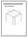
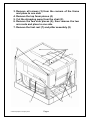
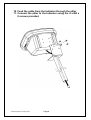
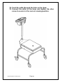
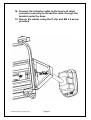
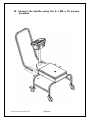
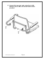
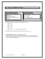
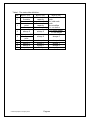
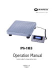
Adam Equipment
MCW – 300L
HEALTH AND FITNESS SCALE with BMI
ADAM EQUIPMENT CO. LTD.
p.n. 700660158 Rev. A2, January 2012
© Adam Equipment Company 2012
© Adam Equipment Company 2012
Page 1
CONTENTS
1.0
2.0
3.0
4.0
5.0
5.1
5.2
6.0
7.0
8.0
9.0
10.0
INTRODUCTION .......................................................................................... 3
TECHNICAL SPECIFICATIONS .................................................................. 3
DISPLAY AND KEY DESCRIPTIONS.......................................................... 4
SETTING UP ................................................................................................ 5
FUNCTION ................................................................................................. 16
WEIGHING ............................................................................................. 16
MEASURING BODY MASS INDEX (BMI) .............................................. 17
CALIBRATION............................................................................................ 18
USER PARAMETERS................................................................................ 19
RS232 COMMUNICATIONS ...................................................................... 20
ERROR MESSAGES ................................................................................. 24
WARNING .................................................................................................. 24
© Adam Equipment Company 2012
Page 1
© Adam Equipment Company 2012
Page 2
1.0 INTRODUCTION
•
The MCW 300L scale is a Digital Health and Fitness Chair Weighing
Scale with Body Mass Index (BMI) readout.
•
It is an accurate electronic device with advanced design and stable
performance.
•
It is designed to measure the weight of a person and compute the BMI
index once the known height of a person is entered via the Indicator
2.0 TECHNICAL SPECIFICATIONS
Maximum capacity
Minimum capacity
Scale division
Division of measurement
Display
Size of Chair
Overall dimension
Net weight
Environment for Use
Power
Battery
Calibration
© Adam Equipment Company 2012
300 kg / 660lb
2 kg / 4lb
0.05kg / 0.1lb
entry via keypad 1cm / 0.5”
LED display
425 mm x 450 mm x 450 mm
16.7” x 17.7” x 17.7”
675mm x 875mm x 950 mm
26.6” x 34.5” x 37.4”
25 kg / 55 lb.
Temperature: 5ºC-40ºC;
Humidity: <85℅ RH
12vDC 500mA adapter
Internal, re-chargeable
6V 4Ah, 50 hours approx.
External calibration through the keypad.
Page 3
3.0 DISPLAY AND KEY DESCRIPTIONS
KEYS
FUNCTIONS
[On/Off /
Zero]
To turn the scale on or off.
To zero the scale if the display drifts from zero.
[Tare] ↵
[Units /
BMI]
[Print /
Hold]
To tare the scale, if necessary. Accept settings as required
To toggle the weighing unit between Kg and Lb. and to select the BMI
function. Move active digit to the right when required.
To lock the reading even if the person to be weighed is moving and
also to print the weight via the RS232 interface. Increase value or
settings when required.
DISPLAY
Kg
Lb
Hold
DESCRIPTIONS
Indicates when the scale is weighing in Kilograms.
Indicates when the scale is weighing in Pounds.
Indicates when the scale has held the weight reading shown on the
display. It will flash until it locks into the stable reading when it will
then remain on for a preset time when it has held the displayed
reading.
Indicates when the scale is displaying the Body Mass Index value.
The charge light will be on when the battery is recharging.
This indicates when the scale is being used with the AC adapter.
BMI
CH
AC
ZERO
NET
This indicator will be displayed in the left corner when the scale
reaches zero.
The Net weight is displayed, Tare weight is at zero.
© Adam Equipment Company 2012
Page 4
4.0 SETTING UP
PACKING LIST
QTY
DESCRIPTION
1
INDICATOR
1
PILLAR
1
HANDLE
1
FOOT REST
1
CHAIR ASSEMBLY
2
ARM RESTS
5
M4 x 8 CROSSHEAD SCREWS
8
M5 x 15 CROSSHEAD SCREWS
4
M5 x 30 CROSSHEAD SCREWS
4
M6 x 20 SOCKET HEAD SCREWS
4
M6 WASHERS
TOOLS REQUIRED
1 x CROSS HEAD SCREWDRIVER
1 x 5MM HEX ALLEN KEY
© Adam Equipment Company 2012
Page 5
MCW UNPACKING AND INSTALLATION PROCEDURES
1. Remove all strapping (1)
2. Lift the outer box away (2)
© Adam Equipment Company 2012
Page 6
3. Remove all screws (3) from the corners of the frame
and place to one side
4. Remove the top foam pieces (4)
5. Cut the strapping away from the chair (5)
6. Remove the two side pieces (6), then remove the two
arm rests and place to one side
7. Remove the foot rest (7) and pillar assembly (8)
© Adam Equipment Company 2012
Page 7
8. Remove the chair base assembly (9) and place to one
side
9. Remove the Indicator (10), seat assembly and handle
(11)
11
9
10
© Adam Equipment Company 2012
Page 8
10. Feed the cable from the Indicator through the pillar
11. Connect the pillar to the Indicator using the 4 x M4 x
8 screws provided
© Adam Equipment Company 2012
Page 9
12. Feed the cable through the tube on the base
13. Connect the pillar to the base and tighten the allen
screw to secure in the correct viewing position
© Adam Equipment Company 2012
Page 10
14. Connect the Indicator cable to the load cell cable
connector ensuring to thread the cable through the
bracket under the base
15. Secure the cables using the P clip and M4 x 8 screw
provided
© Adam Equipment Company 2012
Page 11
16. Connect the handle using the 4 x M5 x 30 screws
provided
© Adam Equipment Company 2012
Page 12
17. Connect the two arm rests using the 4 x M6
washers and 4 x M6 x 20 socket head screws
provided
© Adam Equipment Company 2012
Page 13
18. Place the chair assembly onto the base and secure
using the 4 x M5 x 15 screws provided
© Adam Equipment Company 2012
Page 14
19. Place the foot rest onto the assembly and secure
using the 4 x M5 x 15 screws provided
© Adam Equipment Company 2012
Page 15
5.0 FUNCTION
5.1
WEIGHING
•
Position the Scale on an even floor and press the [On/Off] key.
•
The instrument performs a self-test after which it is ready for operation.
•
Press the [On/Off] key and the machine switches off.
•
The person to be weighed can sit on to the chair once the scale shows
0.0 on the display. The weight will be display in Kg. or lb. depending on
the units chosen by the user.
•
If the weighing value is to be tared press the tare key to remove the
weight value from the display.
•
Press the [Units] key for changing the weighing unit to kg or lb. The
LED will indicate the chosen weighing unit.
•
Overload display: When “FULL” appears on the display, it shows that
the load on the chair is over the maximum capacity. Under these
circumstances, it is necessary to reduce the load otherwise the sensor
or the chair will be damaged.
•
Hold Function: To lock the weighing result, press the [Print/Hold]
key. The LED will flash until a stable reading has been obtained and
then it will light up constantly. The weight will be displayed until the hold
time has expired (see Sec 7.0) or to manually release the function,
press the [Print/Hold] key again.
•
Print Function: To send the weighing result to a printer or computer
press the [Print/Hold] key when the [Print/Hold] key has been set up
in the parameter section to work as print function
© Adam Equipment Company 2012
Page 16
5.2
MEASURING BODY MASS INDEX (BMI)
•
Once the height has been determined it is possible to enter the height
reading into the display ready for the scale to compute the BMI.
•
Press and hold the [Unit/BMI] key to enter the BMI mode. The display
will show the last height value used, “Cm123” or “In123” depending on
which weighing unit you are currently using.
•
The height entry unit (Cm or In) will be flashing to show you which unit
you are currently in, use the Up arrow key to change the height entry
unit between Cm to In as required
•
Enter your height using the arrow keys, the [Print/Hold] /
increment the flashing digit, the right arrow, the [Unit/BMI] /
move the flashing digit to the adjacent digit.
•
Press the [Tare]/↵
↵ key to confirm the value.
•
The display will now show the BMI based on the current weight on the
scale and the height entered.
•
Press the [Unit/BMI] key to exit the BMI mode and return to normal
weighing.
•
The Hold function will work as described above whilst in the BMI mode.
© Adam Equipment Company 2012
Page 17
key will
key, will
6.0 CALIBRATION
Before calibrating the scale, you should ensure that you have a suitable known
weight for calibration.
1. When in normal weighing mode with the scale at zero press and hold down
[TARE] and [ON / OFF] keys to enter the calibration mode.
2. If the calibration switch is in the off position on the main PCB inside the scale, the
indicator will show “CAL.OFF” and then exit this mode. If the indicator shows “CAL?”, the scale is ready for calibration.
3. When the indicator shows “CAL-?”, press the [TARE] key to confirm and go to
next step, or press the [ON / OFF] key to exit the calibration mode.
0.0’ is displayed the scale will begin to calibrate the scale’s zero-point.
4. When ‘0.
Ensure that there is no load or weight on the scale’s chair. Press the [TARE] key
to confirm, or press the [ON / OFF] key to exit this mode.
5. A few seconds after the [TARE] key has been pressed in step 4 the scale will
show “300.0” and the kg LED, or “600.0” and the lb LED depending on which unit
you chosen, this is the default calibration weight from the factory. Press the
[UNIT] key to select the calibration weight unit that you want to calibrate in. Press
the [ON / OFF] key to exit the calibration mode at this point or press the
[Print/Hold] key to choose a different calibration weight value (50kg, 100kg,
150kg, 200kg, 250kg, 300kg or 100lb, 200lb, 300lb, 400lb, 500lb, 600lb); Then
put on the weight that you selected and press the [TARE] key to confirm the
chosen standard weight that was selected earlier. The displayed data will flash
on the display and if the scale accepts the calibration data it will calculate and
store the information into the EEPROM. If an error has occurred, the scale will
display “CAL. Er” and return back to step 4 for re-calibration. If the loaded weight
is not within the range of 95% to 105% of the weight value you selected, the
scale will not calibrate but display “CAL. Er” and return back to step 4 for recalibration. )
6. Check the calibration by putting the weight that you calibrated at back on the
scale, if it is off repeat the calibration process again.
© Adam Equipment Company 2012
Page 18
7.0 USER PARAMETERS
This indicator has 4 parameter settings that can be selected.
1. When the scale is in normal weighing mode, press and hold down the [ON / OFF]
key and the [UNIT] key for 3 seconds until ‘Setup’ is shown on the display.
2. When in the SETUP mode, press the [Print/Hold] key to change the flashing
digits, and [TARE] key to confirm the flashing digits and move to the next
parameter setting. Press the [ON / OFF] key to exit the set up mode.
3. Parameters setting summary:
Parameter
x/xy
Factory Set
A.o.t.
00-15
05
P.H.
0,1,2
1
H.t
0-4
0
S.F.
0-3
0
© Adam Equipment Company 2012
Setting
Auto-off time:
No auto-off = 00.
01-15 minutes auto-off time.
0 = Only Print Function
1 = Only Hold Function
2 = both HOLD and PRINT function (pressed
down less 3s,this key works as Print
function; pressed down more than 3s,this
key works as HOLD function)
Hold time:
0 = no time limit.
1 = 10 seconds
2 = 30 seconds
3 = 60 seconds
4 = 120 seconds
0 = No RS232 Function.
1 = Continuously outputs display data.
2 = Output display data when PRINT pressed
3 = Bi-directional communication (the scale
receives and executes commands from the
HOST device)
Page 19
8.0 RS232 COMMUNICATIONS
The Interface parameters are:
RS-232 output of weighing data
ASCII code
9600 Baud rate (fixed)
1 start bit, 8 data bits,1 stop bit
No Parity
Connection details are:
Connector: 9 pin d-subminiature socket
Pin 2 Output
Pin 3 Input
Pin 5 Signal Ground
8.1 RS-232 connection between the Scale and the Host:
DB9 female
RXD
pin 3
TXD
pin 2
GND
pin 5
Note: Pins 1, 4, 6, 7, 8 and 9 are not connected.
The RS232 function will only operate if PH has been set to 0 or 2.
8.2 When Parameter S.F. in section 7 is set to 0 :
No RS232 function. The scale will not transmit or receive any data although the
scale is equipped with RS232. The RS232 function can be only activated when the
scale is in normal weighing mode.
© Adam Equipment Company 2012
Page 20
8.3 When Parameter S.F. in section 7 is set to 1 :
Continuous output of the current displayed reading and unit, and no data is
received.The output format is as below:
<LF>< reading, minus, decimal point, weight unit>GR<CR><EXT>
Or <LF>< reading, minus, decimal point, weight unit>NT<CR><EXT>
8.4 When Parameter S.F. in section 7 is set to 2 :
Manually outputs displayed data when PRINT is pressed. The output format is as
below:
<LF>< reading, minus, decimal point, weight unit>GR<CR><EXT>
Or <LF>< reading, minus, decimal point, weight unit>NT<CR><EXT>
8.5 When Parameter S.F. in section 7 is set to 3 :
The baud rate and data format are fixed with responses to serial commands being
within 300 milliseconds. One second should be adequate for use as a time-out
value by a remote (controlling) device.
8.5.1 The length of the weight field will be a 7 digit weight data, one for minus sign,
one for decimal point, two for measuring unit (e.g. “lb”, “kg”). Units of measure
abbreviations are always lower case.
If the weight is overcapacity, the scale will return nine ‘^’ characters (the field of
minus sign, decimal point, weight data is filled by ‘^’).
If the weight is under capacity, it will return nine ‘-’ characters (the field of minus
sign, decimal point, and weight data is filled by ‘_’).
If the zero point has an error, it will return nine ‘-’ characters.
The character will be ‘-’ for negative weight or a space character for positive
weight. A minus sign follows after the first digit.
Unused leading zero’s before digits are suppressed.
8.5.2 Key to symbols used
<LF> Line Feed character (hex 0AH)
<CR> Carriage Return character (hex 0DH)
<ETX> End of Text character (hex 03)
<SP> Space (hex 20H)
H1H2H3 Three status bytes. Refer to Table1 for definition.
© Adam Equipment Company 2012
Page 21
<p> Polarity character including minus sign for negative weight and a space
character for positive weight
W1-W7 weight data
<dp> decimal point
U1U2: measure units, kg, lb
8.5.3 Commands and response
(1) Command: W<CR> (57h 0dh)
Response:
<LF>^^^^^^u1u2<CR><LF>H1H2H3<CR><ETX>---over capacity
<LF>______u1u2<CR><LF> H1H2H3 <CR><ETX>---under capacity
<LF>---------u1u2<CR><LF> H1H2H3<CR><ETX>---zero-point error
<LF><p>w1w2w3w4w5w6<dp>w7u1u2<CR><LF>H1H2H3<CR>
<ETX> ---Scale is stable, and the current weight unit is kg or lb. With or
without decimal point and the position is as per the P9 setting and current
unit.
(2) Command: S<CR> (53h 0dh)
Response: <LF> H1H2H3<CR><ETX>
(3) Command: Z<CR> (5ah 0dh)
Response: Zero function is activated and it returns to current scale status, the
same as pressing the ZERO/ON/OFF button:
<LF> H1H2H3<CR><ETX>
If ZERO function cannot be activated, it will return to current scale status.
(4) Command: T<CR> (54h 0dh)
Response: TARE function is activated, and then returns scale status, the same
as pressing the TARE button:
<LF> H1H2H3<CR><ETX>
If TARE function cannot be activated, it will return to current scale status.
(5) Command: U<CR> (55h 0dh)
Response: Changes units of measure and returns scale status with new units,
the same as pressing the UNIT button. The new measuring unit
should be allowed to be used as per P11 setting.
<LF>u1u2<CR><LF> H1H2H3<CR><ETX>
(6) Command: X<CR> (58h 0dh)
Response: power off the scale, the same as pressing the ON/OFF button to
turn off the scale.
(7) Command: all others
Response: Unrecognized command
<LF>?<CR><ETX>
© Adam Equipment Company 2012
Page 22
Table1: The status bits definition:
Bit
Byte 1 (H1)
Byte 2 (H2)
Byte 3 (H3)
0= not under 01=normal work
0=stable
capacity
0
mode
1= not stable 1= under capacity 10= hold work
mode
0= not at zero
0= not over
00=not define
point
capacity
1
1= at zero point 1= over capacity 11= not define
0= gross weight
2
always 0
always 0
1= net weight
0= eeprom OK
3
always 0
always 0
1= eeprom
error
4
always 1
always 1
always 1
5
always 1
always 1
always 1
6
always 0
always 1
always 0
7
parity
Parity
parity
© Adam Equipment Company 2012
Page 23
9.0 ERROR MESSAGES
1.
2.
3.
4.
5.
6.
7.
8.
9.
0¯ ¯ ¯ ¯ ¯
0_ _ _ _ _
Ad¯
Ad ¯ ¯¯
Ad _ _ _ _
EEP.Er
CAL.Er
CAP.-AP
Lo.bAt
FULL
Zero point is over the setting range
Zero is below the setting range
ADC is over max. range;
ADC is below min. range;
There is an error in the EEPROM
There is an error in calibration
The capacity will be displayed
The battery voltage or input power is below 5.6V.
The capacity has been exceeded by the person
on the scale.
10.0 WARNING
•
Do not dismantle the weighing machine without following the necessary
instructions.
•
Do not bounce up and down whilst sitting in the chair. This may damage
the sensor inside.
•
Do not move the weighing machine violently and abruptly. Always move
and put down the weighing machine gently.
•
Wipe any stains with a soft damp cloth using a detergent, then wipe clean
with a dry soft cloth. Do not use organic solutions or boiling water to clean
stains. Do not use a water spray for cleaning.
•
Keep the weighing machine in a dry and clean environment. Do not
expose it to outdoor use or use it in locations near fire, under direct
sunshine or with high temperature.
© Adam Equipment Company 2012
Page 24
Manufacturer’s Declaration of Conformity
This product has been manufactured in accordance with the harmonised European standards,
following the provisions of the below stated directives:
Electro Magnetic Compatibility Directive 2004/108/EC
Low Voltage Directive 2006/95/EC
Adam Equipment Co. Ltd.
Bond Avenue, Denbigh East
Milton Keynes, MK1 1SW
United Kingdom
FCC COMPLIANCE
This equipment has been tested and found to comply with the limits for a Class A digital device,
pursuant to Part 15 of the FCC Rules. These limits are designed to provide reasonable protection
against harmful interference when the equipment is operated in a commercial environment. The
equipment generates, uses, and can radiate radio frequency energy and, if not installed and used in
accordance with the instruction manual, may cause harmful interference to radio communications.
Operation of this equipment in a residential area is likely to cause harmful interference in which case
the user will be required to correct the interference at his own expense.
Shielded interconnect cables must be employed with this equipment to insure compliance with the
pertinent RF emission limits governing this device.
Changes or modifications not expressly approved by Adam Equipment could void the user's
authority to operate the equipment.
WEEE COMPLIANCE
Any Electrical or Electronic Equipment (EEE) component or assembly of parts intended to be
incorporated into EEE devices as defined by European Directive 2002/95/EEC must be recycled or
disposed using techniques that do not introduce hazardous substances harmful to our health or the
environment as listed in Directive 2002/95/EC or amending legislation. Battery disposal in Landfill
Sites is more regulated since July 2002 by regulation 9 of the Landfill (England and Wales)
Regulations 2002 and Hazardous Waste Regulations 2005. Battery recycling has become topical
and the Waste Electrical and Electronic Equipment (WEEE) Regulations are set to impose targets
for recycling.
© Adam Equipment Company 2012
ADAM EQUIPMENT is an ISO 9001:2008 certified global company with more than
35 years experience in the production and sale of electronic weighing equipment.
Adam products are predominantly designed for the Laboratory, Educational, Health
and Fitness, retail and Industrial Segments. The product range can be described as
follows:
-Analytical and Precision Balances
-Compact and Portable Balances
-High Capacity Balances
-Moisture analysers / balances
-Mechanical Scales
-Counting Scales
-Digital Weighing/Check-weighing Scales
-High performance Platform Scales
-Crane scales
-Health and Fitness Scales
-Retail Scales for Price computing
For a complete listing of all Adam products visit our website at
www.adamequipment.com
© Copyright by Adam Equipment Co. Ltd. All rights reserved. No part of this
publication may be reprinted or translated in any form or by any means without the
prior permission of Adam Equipment.
Adam Equipment reserves the right to make changes to the technology, features,
specifications and design of the equipment without notice.
All information contained within this publication is to the best of our knowledge timely,
complete and accurate when issued. However, we are not responsible for
misinterpretations which may result from the reading of this material.
The latest version of this publication can be found on our Website.
www.adamequipment.com
© Adam Equipment Company 2012