1
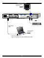
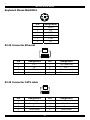
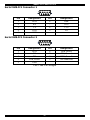
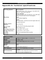
Smart CAT5 Switch 16 IP
Installation Guide
International HQ
North American HQ
European HQ
Italy
Jerusalem, Israel
Linden, New Jersey
Dübendorf, Switzerland
Rome
Tel: + 972 2 535 9666
[email protected]
Tel: + 41 1 823 8000
Tel: + 1 908 4862100
[email protected] [email protected]
www.minicom.com
Tel: + 39 06 8209 7902
[email protected]
Customer support - [email protected]
5UM20112 V1.4 12/03
SMART CAT5 SWITCH 16 IP
Table of Contents
1.
2.
3.
4.
5.
6.
7.
8.
9.
10.
11.
12.
13.
14.
15.
16.
17.
18.
Welcome......................................................................................................................................... 2
Introduction ................................................................................................................................... 3
System components ..................................................................................................................... 3
System features............................................................................................................................. 4
Smart 16 IP front panel ................................................................................................................. 5
The Smart 16 IP rear panel ports ................................................................................................. 5
Pre-installation instructions ......................................................................................................... 6
Connecting the Smart 16 IP system ............................................................................................ 6
The RICCs ...................................................................................................................................... 7
Connecting the CAT5 cables........................................................................................................ 9
Connecting the KVM console....................................................................................................... 9
Connecting the power supply .................................................................................................... 10
Rack mounting the Smart 16 IP ................................................................................................. 10
Rack mounting the RICCs .......................................................................................................... 10
Connecting to Ethernet............................................................................................................... 11
10 Mbps Connection ................................................................................................................... 11
100 Mbps Connection ................................................................................................................. 11
Connecting the RS232 Serial cable ........................................................................................... 11
Appendix A: Pin assignments ............................................................................... 13
Appendix B: Technical specifications .................................................................. 16
1.
I
INSTALLATION GUIDE
1. Welcome
The Smart CAT5 16 IP system is produced by Minicom Advanced Systems Limited.
Technical precautions
This equipment generates radio frequency energy and if not installed in accordance
with the manufacturer’s instructions, may cause radio frequency interference.
This equipment complies with Part 15, Subpart J of the FCC rules for a Class A
computing device. This equipment also complies with the Class A limits for radio
noise emission from digital apparatus set out in the Radio Interference Regulation of
the Canadian Department of Communications. These above rules are designed to
provide reasonable protection against such interference when operating the
equipment in a commercial environment. If operation of this equipment in a
residential area causes radio frequency interference, the user, and not Minicom
Advanced Systems Limited, will be responsible.
Changes or modifications made to this equipment not expressly approved by
Minicom Advanced Systems Limited could void the user’s authority to operate the
equipment.
Minicom Advanced Systems Limited assumes no responsibility for any errors that
appear in this document. Information in this document is subject to change without
notice.
No part of this document may be reproduced or transmitted in any form or by any
means, electronic or mechanical, for any purpose, without the express written
permission of Minicom Advanced Systems Limited.
© 2003 Minicom Advanced Systems Limited. All rights reserved.
Trademarks
PS/2 is a registered trademark of International Business Machines Corporation. All
other trademarks and registered trademarks are the property of their respective
owners.
2.
SMART CAT5 SWITCH 16 IP
2. Introduction
The Smart CAT5 Switch 16 IP (Smart 16 IP) from Minicom Advanced Systems
redirects local keyboard, mouse and video data to up to 16 remote servers. All data
is transmitted via IP.
Smart 16 IP features remote KVM access and control via a LAN or Internet
connection. It provides a non-intrusive solution for remote access and control.
Remote access and control software runs on the Smart 16 IP embedded processors
only and not on the servers, so there is no interference with server operation or
impact on network performance.
The Smart 16 IP can also be used in a multi administrator and multi server
environment. Cascade the Smart 16 IP to access up to 256 remote servers. The
Smart 16 IP combines digital remote KVM access via IP networks with a
comprehensive and integrated system management.
3. System components
•
1 Smart 16 IP box
•
Cables (illustrated below)
•
Remote Interface Connection cables (RICCs) – PS/2, SUN, USB
•
CAT5 cables (1.5m provided)
•
Null Modem cable
•
RS232 Serial cable
•
Rack mounts for the Smart 16 IP and the RICCs
•
VGA Extender cable
•
Marketing & Documentation CD
Figure 1 illustrates a local and remote Administrator managing a 1U server rack with
the Smart 16 IP.
3.
I
INSTALLATION GUIDE
Figure 1 Smart 16 IP usage scenario
4. System features
•
KVM (keyboard, video, mouse) access over IP or analogous telephone line.
•
Advanced On Screen Display management (including multi-layer security)
•
Automatically senses video resolution for best possible screen capture
•
High-performance mouse tracking and synchronization
•
Operate the system using an On Screen Display (OSD) or Control software
or front panel push buttons or keyboard hotkeys
•
Create multi-level cascade arrangements. For example by cascading the
Smart 16 IP 16 Port model, connect up to up to 256 computers in the system
•
Computers can be placed up to 10m/33ft from the Smart 16 IP
•
Multi-platform — supports PS/2, SUN, and USB servers
Smart 16 IP supports PS/2 type keyboards and mice and HD 15 video output. See
the pin assignments in Appendix A.
Smart 16 IP automatically detects the current video mode of the console, however
manual tuning is recommended to get the best video quality. Smart 16 IP will accept
video streams up to 110 MHz dot clock. This results in a screen resolution of
1280x1024 dots with a refresh rate of 75 Hz.
4.
SMART CAT5 SWITCH 16 IP
5. Smart 16 IP front panel
Figure 2 illustrates the Smart 16 IP front panel.
CAT5
SMART
SWITCH
IP
MINICOM
Activity
System OK
www.minicom.com
Figure 2 Front panel
The Reset button resets the Smart 16 IP.
The table below explains the functions of the front panel LEDs.
LED
Function
Activity
LED blinks when Network connection is functioning
System OK
LED solid when IP Link system connected and functioning
6. The Smart 16 IP rear panel ports
The figure below illustrates the ports on the Smart 16 IP rear panel.
Serial 2
Serial 1
SERIAL 2
SERIAL 1
Montor
COMPUTER
9
10
11
12
13
14
15
www.minicom.com
85-265 VAC 50/60 Hz
Computer ports
16
USER
RST
POWER
SERVICE
1
2
3
4
5
6
7
ETHERNET
8
Mouse
Power
Service port
connector
Ethernet
Keyboard
Figure 3 Smart 16 IP ports
You can work locally on the host system by connecting a KVM console to Smart 16
IP rear panel.
5.
I
INSTALLATION GUIDE
Serial 1 port
Serial 1 port is used as follows:
•
IPMI Version 1.5 connection to the remote system using the IPMI Option
cable
•
Serial output for modem dial in connection
•
Serial pass-through via Telnet
•
Initial configuration
Serial 2 port
The Serial 2 port supports the internal and external power options
Ethernet
Connects the Smart 16 IP to an Ethernet network.
7. Pre-installation instructions
•
Place cables away from fluorescent lights, air conditioners and other machines
that are likely to generate electrical noise
•
Switch off all computers
•
Ensure that the maximum distance between each computer and the Smart 16 IP,
does not exceed 10m/33ft
8. Connecting the Smart 16 IP system
1. Connect the power cord and Ethernet and/or modem connection to the Smart 16
IP.
2. Connect each computer to the Smart 16 IP system using the appropriate RICC and
CAT5 cables – explained below.
Figure 4 illustrates the Smart 16 IP system connections with the appropriate RICC
connected to a PS/2, SUN and USB computer.
6.
SMART CAT5 SWITCH 16 IP
Figure 4 Smart 16 IP system connections
9. The RICCs
The RICCs draw their power from the computer’s keyboard port (RICC PS/2, SUN)
or from the USB port (RICC USB).
Connecting a PS/2 RICC
Figure 5 illustrates the RICC.
To connect the PS/2 RICC:
1. Connect the Screen connector to the computer’s Video card.
2. Connect the Keyboard connector to the computer’s Keyboard port.
3. Connect the Mouse connector to the computer’s Mouse port.
7.
I
INSTALLATION GUIDE
NetServer tc2100
To computer’s
keyboard port
Keybd
Mouse
100T
To computer’s
mouse port
Parallel
Serial A
RICC
Video
Serial B
To computer’s
Video card
SCSI
CAT5 cable to Smart
CAT5 Computer port
PCI 33Mx32b
PCI 33Mx32b
PCI 33Mx32b
PCI 33Mx32b
Figure 5 PS/2 RICC
Connecting a SUN RICC
Figure 6 illustrates the SUN RICC and its connections.
To connect the SUN RICC:
1. Connect the Screen connector to the computer’s Video card.
2. Connect the Keyboard connector to the computer’s Keyboard port.
To Computer’s
Video Card
RICC
CAT5 cable to Smart
CAT5 Computer port
Figure 6 SUN RICC
8.
To Computer’s
Keyboard Port
SMART CAT5 SWITCH 16 IP
Connecting a USB RICC
The RICC USB supports Windows 98 SE and later, MAC, SUN and SGI. Figure 7
illustrates the USB RICC and its connections.
To connect the USB RICC:
1. Connect the Screen connector to the computer’s Video card.
2. Connect the USB connector to the computer’s USB port.
To Video Card
To USB Port
RICC
CAT5 cable to Smart
CAT5 Computer port
Figure 7 USB RICC
VGA Extender cable
Where the RICC’s Screen connector won’t reach the computer’s Video card,
connect the VGA Extender cable to the RICC and then follow the instructions
below.
10.
Connecting the CAT5 cables
1. Connect one connector to the RICCs RJ45 port.
2. Connect the other connector to one of the Smart 16 IP’s Computer ports.
3. Follow the above 2 steps for each computer.
11.
Connecting the KVM console
To connect a KVM console to the Smart 16 IP:
1. Connect the monitor’s connector to the Smart 16 IP’s Monitor port.
2. Connect the keyboard’s connector to the Smart 16 IP’s Keyboard port.
3. Connect the mouse’s connector to the Smart 16 IP’s Mouse port.
9.
I
INSTALLATION GUIDE
12.
Connecting the power supply
Connect the Smart 16 IP to the power supply using the Power cable provided.
13.
Rack mounting the Smart 16 IP
Use the plate and screws provided to mount the Smart 16 IP on a server rack as
illustrated below.
CAT5
SMART
SWITCH
IP
MINICOM
Activity
System OK
www.minicom.com
Insert screws to
connect to Switch
side panel
Insert screws to
connect to rack
14.
Rack mounting the RICCs
You can attach the RICCs to a server rack or computer using the Velcro strips
provided. Or connect it using the bracket provided.
The figure below illustrates the bracket.
Insert screws through
bracket and into the
rack
Insert screw through
bracket and into the
back of a computer
Insert screws through
bracket and into the
back of the RICC
Insert screws through
bracket and into the
back of the RICC
10.
SMART CAT5 SWITCH 16 IP
15.
Connecting to Ethernet
The Ethernet connector on the Smart 16 IP can be used either for a 100 Mbps
100BASE-TX connection or for a 10 Mbps 10BASE-T connection. The adapter
adjusts to the appropriate operation mode automatically.
16.
10 Mbps Connection
For 10BASE-T Ethernet networks, the Fast Ethernet adapter uses Category 3, 4, or 5
UTP/FTP cable. To establish a 10 Mbps connection, the cable must be connected to
a 10BASE-T hub. Ensure the cable is wired appropriately for a standard 10BASE-T
adapter. Align the RJ-45 plug with the notch on the adapter's connector and insert it
into the adapter's connector.
17.
100 Mbps Connection
For 100BASE-TX Fast Ethernet networks, the Smart 16 IP supports Category 5
UTP cabling. To establish a 100 Mbps connection, the cable must be connected to a
100BASE-TX hub.
1. Make sure that the cable is wired appropriately for a standard 100BASE-TX
adapter.
2. Align the RJ-45 plug with the notch on the adapter's connector and insert it into
the adapter's connector.
Note! The UTP/FTP wire pairs and configuration for 100BASE-TX cable are
identical to those for 10BASE-T cable when used with Category 5 UTP/FTP cable.
18.
Connecting the RS232 Serial cable
To operate the Smart 16 IP system with the Control software located on the
Marketing & Documentation CD, connect the RS232 Serial cable.
To connect the RS232 Serial cable:
1.
Connect the cable’s RJ11 connector to the Smart 16 IP’s Service port. See
Appendix A for the Service Connector Pin-out.
2.
Connect the cable’s DB9F connector to the computer’s Serial port.
The figure below illustrates the connections.
11.
I
INSTALLATION GUIDE
P110
SD
COMPUTER
9
10
11
12
13
14
15
16
SERIAL 2
SERIAL 1
USER
RST
POWER
SERVICE
1
2
3
4
To Service port
5
6
7
8
ETHERNET
Smart CAT5 16 IP
RS232 Serial
cable
Control software
installed here
To computer’s Serial port
Figure 8 The Smart 16 IP with the RS232 Serial cable
12.
www.minicom.com
100-250 VAC 50/60 Hz
Computer screens
appear here
SMART CAT5 SWITCH 16 IP
Appendix A: Pin assignments
VGA HD-15
5
4
10
3
9
2
8
1
7
6
15 14 13 12 11
Pin
1
2
3
4
5
6
7
8
Assignment
Red
Green
Blue
Not connected
GND
GND red
GND green
GND blue
Pin
9
10
11
12
13
14
15
Assignment
5V
GND sync
Not connected
SDA, DCC, ...
HSYNC
VSYNC
DATA CLOCK
RS232 Serial cable
1
2
6
6
RJ11 Service
1
2
3
4
5
6
3
7
4
8
5
9
1
Assignment
N/C
TXD
RXD
N/C
GND
N/C
13.
DB9
2
3
5
-
I
INSTALLATION GUIDE
Keyboard Mouse MiniDIN 6
6
5
4
3
2
Pin
1
2
3
4
5
6
1
Assignment
DATA
N/C
GND
VCC
CLK
N/C
RJ 45 Connector Ethernet
8
Pin
1
2
3
4
1
Assignment
TX +
TX RX +
Not connected
Pin
5
6
7
8
Assignment
Not connected
RX Not connected
Not connected
Pin
5
6
7
8
Assignment
RJ 45 Connector CAT5 cable
8
Pin
1
2
3
4
1
Assignment
Orange
Orange/White
Blue
Green/White
14.
Green
Blue/White
Brown
Brown/White
SMART CAT5 SWITCH 16 IP
Serial SUB-D 9 Connector 1
1
2
6
Pin
1
2
3
4
5
3
7
4
8
5
9
Assignment
DCD
RX
TX
DTR
GND
Pin
6
7
8
9
Assignment
DSR
RTS
CTS
RI
Serial SUB-D 9 Connector 2
1
2
6
Pin
1
2
3
4
5
3
7
4
8
Assignment
DCD
RX
TX
DTR, Reset1
GND
5
9
Pin
6
7
8
9
Pins 1 and 6 are bridged
15.
Assignment
DSR, Reset2
RTS, Power1
DTS, Power2
Not connected
I
INSTALLATION GUIDE
Appendix B: Technical specifications
Operating Systems
Host computer:
DOS, Novel, Linux, UNIX, Windows 3.1,9X, ME, NT4,
2000, XP, 2003 Server and later
Client computer:
Windows 98, ME, 2000, XP and later, Linux, MAC and
SUN. Internet browser with full Java support
Resolution
Host:
Up to 1280x1024@75Hz
Client:
Recommended - resolution should be higher than host
computer resolution
Switch to server
distance
Up to 10m/33ft
System cable
Mouse
CAT5 UTP/FTP Solid Wire 2x4x24 AWG
Operating temperature
PS/2, Wheel mouse
0°C to 40°C / 32° to 104°F
Storage temperature
-40°C to 70°C / -40° to 158°F
Humidity
80% non-condensing relative humidity
Warranty
3 Years
Smart 16 IP Switch
Dimensions
431mm x 176mm x 41mm / 17" x 6.9” x 1.6”
Weight
2.54Kg / 5.6lbs
Power supply
Internal switching 85-265 VAC 50 / 60 Hz
Connections
System
Serial
Local KVM
RJ45
RJ11
HDD15/MinDin6/MiniDin6
Line connection
RJ45 – LAN, Autosensing 10/100 Mbit/s
Serial connection
2 x DB9:
COM1 for initial configuration and external modem,
COM2 for power management only
16.
SMART CAT5 SWITCH 16 IP
RICCs
PS/2
USB
SUN
VGA
Keyboard/Mouse
System
HDD15
MiniDin6
RJ45
HDD15
USB
RJ45
HDD15
MiniDin8
RJ45
Power
From computer’s
Keyboard port
From computer’s
USB port
From computer’s
Keyboard port
Connections
Weight
Dimensions
107g
91 x 41 x 24mm / 3.58 x 1.61 x 0.94in
17.
I
INSTALLATION GUIDE
18.
SMART CAT5 SWITCH 16 IP
19.