1
Thank you very much for purchasing the STX-8/7
• To ensure correct and safe usage with a full understanding of this product's performance, please be sure to read through this manual
completely and store it in a safe location.
• Unauthorized copying or transferral, in whole or in part, of this manual is prohibited.
• The contents of this operation manual and the specifications of this product are subject to change without notice.
• The operation manual and the product have been prepared and tested as much as possible. If you find any misprint or error, please
inform us.
* This manual is for use with the STIKA PLUS STX-8 as well as with the STIKA STX-7.
Operating environment for
software
Computer
Personal computer running Windows 95, Windows 98, or
Windows NT 4.0
CPU
If you're using Windows 95
i486SX or better (Pentium 100 MHz or more recommended)
If you're using Windows 98 or Windows NT 4.0
i486DX or better (Pentium 100 MHz or more recommended)
Memory
If you're using Windows 95
8 Mbytes or more (16 Mbytes or more recommended)
If you're using Windows 98 or Windows NT 4.0
16 Mbytes or more (32 Mbytes or more recommended)
Hard disk
A hard disk with at least 1.5 Mbytes of free space is required.
CD-ROM drive
Operating system
Windows 95, Windows 98, or Windows NT 4.0
Contents
To Ensure Safe Use .............................................................. 1
About the Labels Affixed to the AC Adapter ........... 2
1. Check the included items .................................................... 3
2. Connect to the computer ...................................................... 3
3. Load the material ................................................................. 4
4. Power ON! ........................................................................... 6
5. Perform Test Cutting ........................................................... 6
6. Adjusting the Amount of Blade Extension .......................... 7
7. Overview of Dr.STIKA PLUS ............................................ 9
8. The Basics of Windows ....................................................... 9
9. Setting Up the Software ...................................................... 9
10. Make Data with Dr.STIKA PLUS ..................................... 14
11. Perform cutting ................................................................... 18
12. Applying the Completed Cutout ........................................ 20
13. Switch off the Power ......................................................... 20
14. Draft Plotting ..................................................................... 21
15. Editing Shapes and Text .................................................... 22
16. Operations for Cutting ....................................................... 30
17. Care and cleaning .............................................................. 32
18. What to do if... ................................................................... 33
Specification ............................................................................ 34
Option Lists ............................................................................. 34
For the USA
FEDERAL COMMUNICATIONS COMMISSION
RADIO FREQUENCY INTERFERENCE
STATEMENT
This equipment has been tested and found to comply with the
limits for a Class A digital device, pursuant to Part 15 of the
FCC Rules.
These limits are designed to provide reasonable protection
against harmful interference when the equipment is operated
in a commercial environment.
This equipment generates, uses, and can radiate radio
frequency energy and, if not installed and used in accordance
with the instruction manual, may cause harmful interference
to radio communications.
Operation of this equipment in a residential area is likely to
cause harmful interference in which case the user will be
required to correct the interference at his own expense.
Operating Instructions
KEEP WORK AREA CLEAN. Cluttered areas and benches
invites accidents.
DON’T USE IN DANGEROUS ENVIRONMENT. Don’t
use power tools in damp or wet locations, or expose them to
rain. Keep work area well lighted.
DISCONNECT TOOLS before servicing; when changing
accessories, such as blades, bits, cutters, and like.
REDUCE THE RISK OF UNINTENTIONAL STARTING.
Make sure the switch is in off position before plugging in.
USE RECOMMENDED ACCESSORIES. Consult the
owner’s manual for recommended accessories. The use of
improper accessories may cause risk of injury to persons.
NEVER LEAVE TOOL RUNNING UNATTENDED.
TURN POWER OFF. Don’t leave tool until it comes to a
complete stop.
Unauthorized changes or modification to this system can void
the users authority to operate this equipment.
The I/O cables between this equipment and the computing
device must be shielded.
For Canada
CLASS A
NOTICE
This Class A digital apparatus meets all requirements of the
Canadian Interference-Causing Equipment Regulations.
CLASSE A
AVIS
Cet appareil numérique de la classe A respecte toutes les
exigences du Règlement sur le matériel brouilleur du
Canada.
ROLAND DG CORPORATION
1-6-4 Shinmiyakoda, Hamamatsu-shi, Shizuoka-ken, JAPAN 431-2103
MODEL NAME
: See the MODEL given on the rating plate.
RELEVANT DIRECTIVE : EC MACHINERY DIRECTIVE (89/392/EEC)
EC LOW VOLTAGE DIRECTIVE (73/23/EEC)
EC ELECTROMAGNETIC COMPATIBILITY DIRECTIVE (89/336/EEC)
Windows®, and Windows NT® are registered trademark or trademark of Microsoft® Corporation in the United States and/or other countries.
TrueType is a trademark of Apple Computer, inc.
i486 and Pentium are registered trademarks of Intel Corporation in the United States.
CorelDRAW is a trademark of COREL Corporation
ATM, Adobe Type Manager and Adobe Illustrator are registered trademarks or trademarks of Adobe Systems Incorporated in the United
States and/or other countries.
* Other company and product names appearing herein are trademarks or registered trademarks of their respective holders.
Copyright © 1997- 1998ROLAND DG CORPORATION
To Ensure Safe Use
About
and
Notices
Used for instructions intended to alert the user to the risk of death or severe
injury should the unit be used improperly.
Used for instructions intended to alert the user to the risk of injury or material
damage should the unit be used improperly.
* Material damage refers to damage or other adverse effects caused with
respect to the home and all its furnishings, as well to domestic animals or
pets.
About the Symbols
The
symbol alerts the user to important instructions or warnings. The specific meaning of
the symbol is determined by the design contained within the triangle. The symbol at left means
"danger of electrocution."
The
symbol alerts the user to items that must never be carried out (are forbidden). The
specific thing that must not be done is indicated by the design contained within the circle. The
symbol at left means the unit must never be disassembled.
The
symbol alerts the user to things that must be carried out. The specific thing that must
be done is indicated by the design contained within the circle. The symbol at left means the
power-cord plug must be unplugged from the outlet.
Do not disassemble, repair, or
modify.
Doing so may lead to fire or abnormal
operation resulting in injury.
Do not use with any power supply
other than the dedicated AC adapter.
Use with any other power supply may lead
to fire or electrocution.
Do not injure or modify the electrical
power cord, nor subject it to
excessive bends, twists, pulls,
binding, or pinching, nor place any
object of weight on it.
Doing so may
damage the
electrical power
cord, leading to
electrocution or
fire.
Use only with a power supply of the
same rating as indicated on the AC
adapter.
Use with any other power supply may lead
to fire or electrocution.
Do not use while in an abnormal
state (i.e., emitting smoke, burning
odor, unusual noise, or the like).
Doing so may result in fire or electrical
shock.
Immediately unplug the AC adapter from
the electrical outlet, and contact your local
vendor or Roland sales center.
When unplugging the AC adapter
from the power outlet, grasp the
adapter unit or the plug, not the
cord.
Unplugging by pulling the cord may damage
it, leading to fire or electrocution.
1
Do not use with a damaged AC
adapter or power cord, or with a
loose electrical outlet.
When not in use for several hours,
unplug the AC adapter from the
electrical outlet.
Use with any other
power supply may
lead to fire or
electrocution.
Failure to do so may
result in danger of
shock, electrocution,
or fire due to
deterioration of the
electrical insulation.
Do not touch the tip of the blade
with your fingers.
Install on a stable surface.
Doing so may result in injury.
Failure to do so
may result in
falling of the unit,
leading to injury.
Do not allow children to operate
without adult supervision or operate
within reach of young children.
Doing so may result in injury.
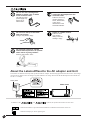
About the Labels Affixed to the AC adapter and Unit
These labels are affixed to the body of this product and the AC adapter. The following figure describes the location. The configuration of the AC adapter varies according to regional differences in voltage. Please note that the descriptions in this manual are
for the 117 V adapter.
Rating label
Model name
In addition to the
and
symbols, the symbols shown below are also used.
: Indicates information to prevent machine breakdown or malfunction and ensure correct use.
: Indicates a handy tip or advice regarding use.
2
How to use this manual
In this manual, the names of the products covered appear as
follows. STIKA PLUS STX-8
STIKA PLUS STX-8
STIKA STX-7
= STX-8
= STX-7
Sections that describe identical procedures for the two models are
indicated as follows.
STX-8/7
The illustrations appearing in this manual depict the STX-8. The STX-7 may differ from the product shown.
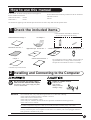
1
Check the included items
* The blade holder and blade are installed on
the unit when shipped from the factory.
Roland Software Package : 1
Material for test cuts : 1
* Paper : 1
AC adapter : 1
Application tape for test cuts : 1
Blade holder : 1
* Sheet setup guide : 1
Blade : 1
* Water based fiber tipped pen : 1
STX-8/7 User's Manual : 1
The configuration of the AC adapter varies according to
regional differences in voltage. Please note that the
descriptions in this manual are for the 117 V adapter.
* Included only with the STX-8.
2
Installing and Connecting to the Computer
Do not use with any power supply
other than the dedicated AC adapter.
Use with any other power supply may lead
to fire or electrocution.
NOTICE
Install on a stable surface.
Failure to do so
may result in
falling of the unit,
leading to injury.
Never install this unit in any of the following situations, as it could result in damage:
• Places where the installation surface is unstable or not level.
• Places with excessive electrical noise.
• Places with excessive humidity or dust.
• Places with poor ventilation, because the STX-8/7 generates considerable heat during operation.
• Places with excessive vibration.
Use within a temperature range of 5 to 40°C (41 to 104°F) and within a humidity range of 35 to 80%.
Make sure the power to the computer and the STX-8/7 is switched off before attempting to connect the cables.
Securely connect the power cord, computer I/O cable and so on so that they will not be unplugged. Otherwise,
faulty operation or breakdown may result.
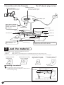
3
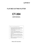
Connect the unit to the Computer
The AC adapter plugs in here
Parallel connector
Parallel connector
Use the clips on either side to
secure the connector in place.
Use the clips on either side to
secure the connector in place.
AC adapter jack
The cable is available
separately. Be sure to
use the correct cable for
the computer.
Parallel Cable
Blade carriage
Front cover
STANDBY LED
Screw
STANDBY key
Sheet feed knob
50 mm
(1-15/16")
Do not place any object
within the area.
3
Blade protector
Subrollers
Pinch rollers
Do not place any objects within the range of material
movement to the front or rear of the unit.
Load the material
Material of the following composition and thickness can be cut.
- Composition
Vinyl chloride sheets
- Thickness
Sheet portion :0.1 mm (0.00394") or less, including base paper of 0.3 mm (0.0118) or less
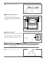
Do not use any of the following materials. The material may come loose during cutting or otherwise fail to be fed properly.
Materials which has
curled upward
Material with a front edge
that is not straight
Material with left and right
edges that are not parallel
Material that is longer than
1 m 10 cm (43-1/4")
Loading the material
1
Place the material against the pinch rollers.
Load the material as shown in the figure, so that it does not
come loose during cutting.
Pinch rollers
Make sure the two sides of the material are even
4
2
Turn the sheet feed knob to align the forward edge of the
material with the back of the blade protector.
Blade protector
Sheet feed knob
About the cutting range
The cutting range is inside the dotted box.
Blade Holder
• The sheet behind the cutter holder cannot be cut.
• The front and the left and right side of the material are
necessary margins to allow feed of the material by the
pinch rollers.
Blade protector
Pinch roller
1000 mm
(39-5/16")
STX-8: 250 mm (9-13/16")
STX-7: 160 mm (6-1/4")
STX-8: 280—305 mm (11"—12")
STX-7 : 200—215 mm (7-13/16"—8-7/16")
Material
30 mm
(1-3/16")
Using roll material
The STX-8/7 can be loaded with material up to 1100 mm (43-1/4")
in length. However, the cutting area is only up to 1,000 mm (39-5/
16").
When using roll material, cut off from the roll a piece of material
that is equal to the length required for cutting, plus a margin, and
load this cut piece on the STX-8/7 for cutting. Material cannot be
loaded on the STX-8/7 while still attached to the roll.
Using lengthy material
NOTICE
(STX-8 only)
Once the sheet setup guide has been affixed, do not peel it off. Doing so may damage the tape surface of the
sheet setup guide, making it unusable. Also, if peeled off, some tape surface may remain on the STX-8,
adversely affecting cutting.
Using the included sheet setup guide makes it possible to load lengthy material accurately.
1
Peel off the backing paper for the sheet setup guide.
5
2
Align the marks on the sheet setup guide with the left and
right edges of the blade protector. At the same time, align
the tip of the sheet setup guide with the tip of the blade
protector and affix.
Blade protector
Sheet setup guide
Align the guide lines on the sheet setup guide with the left
and right edges of the material, and turn the sheet feed
knob.
* Depending on the material width, the left and right edges
may not be perfectly aligned.
4
Guide lines
Material
Power ON!
1
Close the front cover and press the STANDBY key.
2
The STANDBY LED lights up and the carriage moves as
shown in the figure, then stops.
Front cover
STANDBY key
* Slight noise may be heard when the
carriage changes direction.
5
Perform Test Cutting
NOTICE
Be sure to load a piece of material, or the pinch rollers may be damaged.
Do not move the carriage by hand. Doing so may result in breakdown.
Do not attempt to move the carriage by hand.
6
With test cutting, the STX-8/7 actually cuts the material, allowing you to determine how well cutting is performed. Test cutting is
performed when using for the first time or when changing the type of material.
How to perform test cutting
1
Hold down for 2 seconds or more while the STANDBY LED
is lit. Remove your finger when the carriage begins to move.
2
Begin the test cut at that position.
To return the position of the carriage to the left-hand
edge to perform test cutting again, switch the power off
and back on.
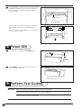
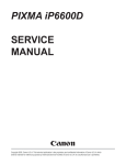
Verification
Check the cut quality of the material. The cutting quality is affected by the amount of blade extension. Try peeling the cut sheet, and use
the blade holder to adjust the amount of blade extension accordingly. (See "6 Adjusting the Amount of Blade Extension.")
The blade leaves faint traces on the
backing paper when cutting the cross.
Optimal amount of
blade extension
6
The sticker cannot easily be
peeled off of the backing paper
Amount of blade extension is too short
The blade cuts into the backing paper
The backing paper is cut through
Amount of blade extension is too long
Adjusting the Amount of Blade Extension
Do not touch the tip of the blade
with your fingers.
Doing so may result in injury.
NOTICE
If the surface under the material is rigid, attempting to cut the sheet while holding the blade holder by hand
may cause the blade to break. Place a sheet or cardboard or the like under the material as a cushion.
When mounting the blade holder, take care not to overtighten the blade retaining screw. The cutter mounting
screw may be broken.
The optimal amount of blade extension is the same value as the thickness of the material (not including backing paper).
* The amount of blade extension of the blade holder included with the STX8/7 is preset at 0.1 mm (0.00394"). When using for the first time, adjust the
amount of blade extension only if the material is not cut correctly when a
test cut is performed.
7
1
Loosen the screw and pull out the blade holder.
Blade holder
Screw
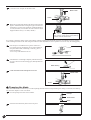
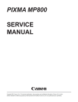
2
Rotate the tip of the blade holder in the direction shown in the
figure to extend the blade. Turning the tip by an amount corresponding to one large scale gradation extends the blade by
0.1 mm (0.00394"). The amount of blade extension when
shipped from the factory is 0.1 mm (0.00394").
Extend the blade tip by 0.1 mm (0.00394").
Only a barely visible portion of the blade tip
protrudes from the blade holder.
It is possible to check the cutting quality of the material without installing the blade holder. However, this method is used as a guide to
avoid extending the blade too far. After using this method to make adjustment, be sure to perform a test cut to verify the cutting quality.
3
Place the piece of cardboard serving as the cushion on a
level surface, then lay the material on top of the cardboard.
Grasp the blade holder, and holding it vertically, place it
against the material.
* Use a scrap of the material to be cut.
4
If the material is cut through completely with the blade leaving only a faint trace on the backing paper, then adjustment is
finished.
Blade leaving
5
Insert the blade holder and tighten the screw.
Blade holder
Screw
Changing the blade
If the material is still not cut attractively even after adjusting the blade extension and performing test cutting several times, the blade tip
may be broken. Replace it with a new blade.
1
Press the push-pin and remove the old blade.
Push pin
Blade holder
Blade
2
8
Insert the new blade firmly until it clicks into place.
7
Overview of Dr.STIKA PLUS
Here's what Dr. STIKA PLUS can do.
- Input text with TrueType fonts
- Input squares, circles, and other simple shapes
- Rotate or slant shapes and text
- Changing the tickness (weight) of text
- Inserting and registering a symbol
- Tiled cutting for sizes larger than the cutting area
- Precise positioning with grid display
- Import data from commercial software packages
This user's manual provides basic information about the various functions of Dr. STIKA PLUS. For more detailed information, please
read the help files for Dr. STIKA PLUS and STIKA PLUS Driver.
8
The Basics of Windows
Mouse operation
Pointing
When you move the mouse, the on-screen arrow (mouse pointer)
also moves. Moving the mouse pointer to line up the tip of the
pointer with an item on the screen is called "pointing."
Click
Press and release the left mouse
button.
Click the right mouse
Press and release the right
mouse button.
Drag
Move the mouse while holding
down the mouse button.
Double click
Rapidly press and release
the left mouse button two
times.
9
Setting Up the Software
The explanations in this manual assume that you are already familiar with the basic operation of Windows.
Compatible Software
The Roland Software Package includes the following software that you can use with the STX-8/7. Software other than what is shown
below cannot be used.
• Programs
• Drivers
: Dr.STIKA PLUS
: If you're using the STX-8 Roland STIKA PLUS STX-8
If you're using the STX-7 Roland STIKA STX-7
Installing Dr. STIKA PLUS
* When setting up the software under Windows NT, log on as the member of a group other than [Guest].
1
Switch on the computer and start Windows.
2
Place the CD from the Roland Software Package in the CDROM drive.
9
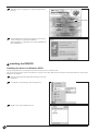
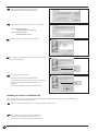
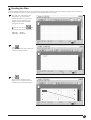
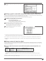
3
When the screen at right appears, click [Dr.STIKA PLUS][Install].
Click this button.
4
The Dr.STIKA PLUS setup screen appears. Follow the onscreen messages to complete the installation.
When installation is completed, remove the CD-ROM from
the CD-ROM drive.
Installing the DRIVER
Installing the driver for Windows 95/98
If you're using Windows 95 or Windows 98, follow the steps below to install the driver.
The screens shown in these steps are for Windows 95. These screens may differ in places from the screens for Windows 98, but the steps
themselves are identical.
10
1
Place the CD from the Roland Software Package in the CDROM drive.
2
Click [Start]. Click [Settings], then click [Printers].
3
Double-click on the [Add Printer] icon.
4
Click [Next].
5
Click [Local printer], then click [Next].
* If this screen doesn't appear, see the next step.
6
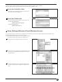
Click [Have Disk...].
7
Click [Browse...].
8
Click the drop-down arrow for [Drives], then select the CDROM drive.
9
Double-click the [drivers] - [win95_98] - [Stika] folder,
then click [OK].
11
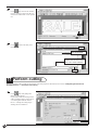
10
Make sure the [STIKA] folder displays [Copy
manufacturer's files from:], and click [OK].
11
Click on the model name to choose it, then click [Next].
If you're using the STX-8:
[Roland STIKA PLUS STX-8]
If you're using the STX-7:
[Roland STIKA STX-7]
12
Make sure [LPT1: ] is selected, then click [Next].
13
To make this the default printer, click [Yes]. Otherwise click
[No], then click [Next].
14
Click [No], then click [Finish].
Copying of the files from the CD-ROM starts.
After all the files have been copied, a printer icon appears in
the [Printers] folder, and installation of the driver is
complete.
Remove the CD-ROM disk from the CD-ROM drive.
Installing the driver for Windows NT
Take a look at the help screens for the Roland Software Package CD-ROM for information on how to install the driver.
Read on to learn how to display the help screens.
12
1
Place the CD in the CD-ROM drive on a computer running Windows NT 4.0.
2
The program selection screen appears automatically.
At this screen, click [How to install the Driver].
The help screen for the installation procedure appears.
This help contains common information about the driver for Windows NT that is on the CD-ROM.
Follow the steps below to display the items that are exclusively for the STIKA driver.
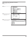
Choose the destination folder
When the screen at right appears, double click [drivers][win_nt4]-[stika] then click [Open].
Choose the STIKA model
Click on the model name to choose it, then click [Next].
If you're using the STX-8:
[Roland STIKA PLUS STX-8]
If you're using the STX-7:
[Roland STIKA STX-7]
Driver Settings (Windows 95 and Windows 98 only)
If you're using the driver for Windows 95 or Windows 98, then make the settings below. When making settings immediately after
installing the STIKA PLUS Driver, continue from step 2.
If you're using the driver for Windows NT, no settings are needed.
* The screens shown in these steps are for Windows 95.
1
Click [Start]. Point to [Settings], then click [Printers].
2
Click the right mouse button on the [Roland STIKA PLUS
STX-8] icon (or the [Roland STIKA STX-7] icon), then
click [Properties].
3
Click the [Details] tab, then set [Timeout setting] to 100
seconds. Click [OK]. This completes the settings for the
driver.
13
10 Make Data with Dr.STIKA PLUS
This section explains the basic operation of Dr. STIKA PLUS while making the sticker shown below. For information on editing and
operation to match the task at hand, please refer to "14 Draft Plotting" to "16 Operations for Cutting," or to the help for Dr. STIKA PLUS
and the driver.
SALE
Starting the Software
1
Click [Start], and point to [Program]. Then point to [Roland
Dr. STIKA PLUS] and click [Dr. STIKA PLUS].
2
The opening screen appears and Dr. STIKA PLUS starts.
Using help
When creating data, if you're unsure about how to proceed, follow the steps below to view the help screens. Also, when carrying out an
operation for the first time, you can display help on your computer to guide you as you proceed.
Displaying help screens
1
14
From the [Help] menu, click [Contents].
2
Click the mouse on text (or figures) in green to display an
explanation or related information.
Green
Using the [?] button and [Help] button
1
If the window you're in has a [?] button in the upper righthand corner, you can use this button to display contextsensitive help. Click [?], then click the item you wish to
know more about.
2
If there is a [Help] button in a window, you can use this
button to display help about the window.
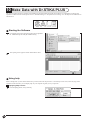
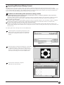
Setting the cutting range
1
From the [File] menu, click [Print
Setup].
2
For the STX-8, select [Roland STIKA
PLUS STX-8]. For the STX-7, select
[Roland STIKA STX-7]. Then click
[Properties].
* The screen at right is shown when
[Roland STIKA PLUS STX-8] has been
selected.
15
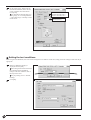
3
Set the cutting range. When using the
included sheet material, make sure the
screen at right has the values shown.
Click [Tools].
For information about the STX-8/7's
cutting range, see "3 Loading Material"
- "The cutting range" or the help screens
for the driver.
* Width is a fixed value.
STX-8: 250 mm (9.84")
STX-7: 160 mm (6.29")
390 mm (15.35")
270 mm (10.63")
Setting the tool conditions
When using the included blade, there is no need to change the tool conditions. At this time, simply check the settings to make sure they're
appropriate.
16
1
Make sure [Machine Settings] is
displayed and click [OK].
When using sheet material other than
the included material and making
changes in the tool conditions, refer to
the help for the driver.
For pen plotting, refer to "14 Draft
Plotting."
2
Click [OK].
Creating the Data
The fonts that Dr. STIKA PLUS can use are limited to the TrueType fonts available for Windows. When selecting a font, non-TrueType
fonts are not displayed. Refer to the help screens for more information about using fonts.
1
The white area of the screen is the
cutting range. Any portions that
protrude beyond this area are not cut.
Use the zoom out function for Dr.
STIKA PLUS to display the entire
cutting area on screen.
To zoom in or out, click
, then
click on the desired area of the screen.
Left click:
Zoom in
Right click: Zoom out
2
Click
.
Click at the desired location, then enter
"SALE" using the keyboard.
1. Type in the text
3
Click
.
Drag a text box with the mouse to
change its size. Change the size to fit
inside the white portion of the display.
17
4
Click
. This encloses the "SALE"
text in a rectangle so that only the area
of the sheet around what is cut is peeled
off.
Drag
5
Click
and save the data you've
made to a file.
1. Click
2. Select where the
file is to be saved.
3. Type in the file name. Files
created with Dr.STIKA PLUS
have ".stx" as the extension.
4. Click
11 Perform cutting
Before performing cutting, make sure the STX-8/7 has been prepared as described in the sections "3 Adjusting the Amount of
Blade Extension" to "6 Perform Test Cutting."
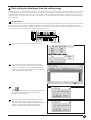
1
Click
, then click [OK] in the
dialog box that appears.
If you wish to make the settings for the
cutting conditions again, please refer to
"10 Creating Data with Dr. STIKA
PLUS" - "Setting the cutting range" "Setting the tool conditions."
1. Click
2. Click
18
If you want to stop cutting before it's finished...
1
Press the STANDBY key to switch off
the power.
2
Click [Start]. Click [Settings], then click
[Printers].
3
For the STX-8, double-click the [Roland
STIKA PLUS STX-8] icon. For the
STX-7, double-click the [Roland
STIKA STX-7] icon.
4
At the [Printers] menu, click [Purge Print
Jobs]. Make sure the displayed data for
the file being printed disappears.
19
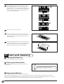
12 Applying the Completed Cutout
When storing material that has been cut, be sure to cover it with application tape. This protects the material
against dust.
1
Rotate the material feed knob and remove the sheet.
2
Peel off excess portions of the sheet. (Commercially available tweezers can be handy for peeling detailed areas and other
hard-to-peel places.)
3
Cover evenly with application tape so that no air bubbles are
trapped between the tape and the material, then transfer the
material to the tape.
4
Wipe away any dust or oil from the location where the material is to be applied.
5
When transferring the material to the object, air may get between the material and the transfer surface, forming air
bubbles. If this happens, use a needle to puncture the bubbles,
then press out the trapped air and affix the material to the
transfer surface.
Place the entire piece of application tape against the object,
then press down evenly on the tape, working from top to bottom. While constantly making sure the material has been transferred to the object, slowly peel away the application tape.
13 Switch off the Power
When not in use for several hours,
unplug the AC adapter from the
electrical outlet.
Failure to do so may
result in danger of
shock, electrocution,
or fire due to
deterioration of the
electrical insulation.
Press the STANDBY key to switch off the power. Make sure the STANDBY LED is not lit up.
20
14 Draft Plotting
Draft plotting is used to plot a design on paper instead of cutting it into material, thereby enabling the cutting results to be verified before
actual cutting is performed. The results of draft plotting can be examined to make any necessary corrections in the data before actually
cutting the material.
NOTICE
1
After using a pen, be sure to remove the pen from the carriage, then cap it securely before putting it away. If
not capped tightly, the pen tip may dry out, making the pen unusable.
Uncap the pen and insert the pen in the carriage. Make sure
the pen's collar is flush with the carriage.
Collar
2
Use the same procedure described under "3 Loading
Material" to load a sheet of paper.
3
Refer to "10 Creating Data with Dr. STIKA PLUS" "Setting the tool conditions" to display the [Tools] tablet
shown at right. Select a value from [1] to [8] as the setting.
4
Select [Test] for the setting.
* The [Pen] function appearing in the screen at right is
available only for the [Roland STIKA PLUS STX-8]. When
using the [Roland STIKA STX-7], this function is not
shown.
5
Follow the steps under "10 Performing Cutting" to output
the data. This performs a draft plot of the data you've
created. After draft plotting, change the location of the
check-mark in step 3 to [Cutting], then carry out cutting.
6
Remove the pen from the carriage and cap the pen securely.
21
15 Editing Shapes and Text
Dr. STIKA PLUS lets you take shapes that have been drawn and edit them in a wide variety of ways. Shapes and text created with Dr.
STIKA PLUS are collectively known as "objects."
Shapes Unsuitable for Cutting
The shapes shown below are not suitable for cutting. When editing objects, you should avoid creating shapes like these.
Open shapes
A shape is called an "open shape" when its start point and end point do not coincide. An open shape is not suitable for cutting, because
the sheet cannot be peeled off after the shape has been cut.
Partially overlapping shapes
Data like that in the figure below, where two shapes partially
overlap, is not suitable for cutting. Objects should be arranged so
that shapes do not overlap.
Shapes that overlap are suitable for use as cutting data when one
shape is completely enclosed within another.
Editing objects
Enlarging, shrinking, and corners
Clicking on an object makes some marks appear around it. These
The object's size can be changed
freely by dragging. To make an
object larger (or smaller) while retaining the same vertical and horizontal proportions, hold down the
[Shift] key while dragging.
and
marks can be dragged to change the object's size.
Drag to make the object larger
(or smaller) in the vertical
direction.
Drag to make the object larger
(or smaller) in the horizontal
direction.
Rounded-corner rectangles and start-shaped object are displayed with the mark shown below in addition to the marks just described.
Drag to enlarge (or reduce) the
radius of the rounded corners.
22
Drag to make the angles more
acute (or more obtuse).
Rotation, slanting, and text spacing
When an object has been selected by clicking on it, clicking once more causes the shape of the marks to change. The and marks can
then be dragged to rotate or add slanting to the object.
Drag to rotate
the shape.
Drag to add slant
to the shape.
A text string is displayed with the following marks in addition to those just described.
Drag to make the
spacing between characters wider (or narrower).
Editing by changing the numerical values
1
Click the right mouse button on the object, then click
[Properties].
2
The [Object Property] dialog box appears. Here you can
edit the object by entering numerical values. The items that
can be edited vary according to the object. For a detailed
description of these setting items and their ranges, please
refer to the help screens for Dr. STIKA PLUS.
Making text thicker
1
Click the right mouse button on the text, then click [Properties].
2
The [Text Property] dialog box appears. Drag the [Character
thickness] slider. Click [OK].
3
The thickness of the text changes with the position of the
slider.
Left end: Standard thickness
Right end: Maximum thickness
Standard thickness
Maximum thickness
23
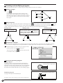
Creating and modifying polygons
This section describes the steps for creating a polygon, using the shape of an arrow as an example.
Creating a polygon
1
7
Click
.
Click the mouse at the desired location, then move the
mouse to draw a line from the point you clicked at. Click
the mouse in the sequence of shown in the figure at right. At
the seventh point, double-click the mouse to finish making
the polygon.
5
6
4
1
3
2
Editing the points
To edit (move, add, or delete) the points (apices) of the polygon, click
. Then, clicking on a point makes it change to
, allowing
the point to be moved or deleted. To select two or more points, either hold down the [Shift] key as you click on each point, or drag the
mouse over the points to be selected. To add a point, click on one of the polygon's lines and press the [Insert] key.
Adding a point
Moving a point
Drag to move the point.
Deleting a point
Click the mouse at the location where the
new point is to be added. A appears at the
location clicked. A point can be added by
pressing [Insert] while in this state.
Click on the point
to be deleted. Press [Delete] to delete
the point.
Converting to a polygon
An object that is not a polygon can be converted to a polygon, and its points edited. Once an object has been converted to a polygon,
however, it cannot be changed back to its original attributes. For details, please refer to the help screens for Dr. STIKA PLUS.
1
Select the object you wish to convert to a polygon. At the
[Object] window, click [Convert to Polygon].
After conversion, clicking
to be edited as with a polygon.
enables the object's points
Joining and separating polygons
Joining polygons
A number of objects can be grouped together and united into a
single polygon. They can then be moved or resized while maintaining the layout the objects had before they were joined together.
The points of an object polygon that has been joined together in
this fashion can be edited in the same way as an ordinary polygon.
Separating polygons
A polygon can be split into individual parts.
For details, please refer to the help screens for Dr. STIKA PLUS.
24
Can be treated as a single object
Can be treated as separate objects
A
When an object cannot be selected...
All objects maintain a certain front-to-back relationship when they overlap. This hierarchy depends on the sequence in which the objects
were created, with newer objects existing more to the front than older ones. When a smaller object lies behind a larger one, the smaller
object cannot be selected. To select the smaller object, change the front-to-back relationship of the larger and smaller objects. This frontto-back relationship between objects can be changed at any time.
1
2
In the figure at right, the large circle is positioned in front of
the smaller one. Select the large circle.
Click
.
The large circle is positioned behind the other one. The
smaller circle that was in back and could not be selected is
now in front and can be selected.
Arranging multiple objects
The on-screen lines that resemble graph paper are called a grid. This grid can be used as a guide for determining the size and positioning
of objects. In addition, activating [Snap To Grid] causes objects to automatically be aligned with the grid lines. This feature is used when
accurate placement or precise sizing for objects is desired. Please refer to the relevant help screens for more about making settings for
grid conditions.
1
To cause objects to be automatically placed on the grid
lines, display the [View] menu and click [Snap To Grid].
Importing an object from another Dr. STIKA PLUS file
An object saved in another file can be added to the file for the object now being edited. This makes it possible to re-use objects that have
been previously created and saved.
1
From the [File] menu, click [Import...].
2
Choose the file and click [Open].
3
The object is added to the file being edited. This newly
added object can be edited in the same ways as any ordinary
object.
25
Using symbols
Dr. STIKA PLUS is provided with a set of symbols. These symbols can be added to any file being edited with Dr. STIKA PLUS.
Frequently used objects in Dr. STIKA PLUS can also be registered and added to the set of symbols.
Importing a symbol
1
From the [Object] menu, click [Symbol].
The [Symbol] dialog box appears.
2
Select the symbol to be used, and click [Insert].
3
The imported symbol appears. You can adjust its size and
position.
Registering a symbol
26
1
Select the object to be registered as a symbol.
2
From the [Object] menu, click [Add Symbol].
The [Add Symbol] dialog box appears.
3
Symbols being registered can be grouped according to use
or shape. To create a new group, click [New Group] and
enter a name for the group. To add the object to an existing
group, select the group name with [Group Name].
4
At [Symbol Name], enter a name for the symbol. Then click
[Add].
Pasting a graphic created with commercial software into Dr. STIKA PLUS
You can copy data created with software such as CorelDRAW! that uses vector data (*1) , and paste the data into Dr. STIKA PLUS using
the clipboard. (*2) The data pasted in can then be edited just like any ordinary object.
Please note that data created using Dr. STIKA Plus cannot be pasted into other software applications.
Conditions for data that can be pasted
• Don't include bitmap data (*3)
• Don't fill or apply shading inside shapes
• Set line width to the finest (narrowest) available setting
1
After using a commercial software application to create
data, select the data and copy it. For information on how to
create data with the commercial software application, refer
to the documentation for the software you are using.
2
From the [Edit] menu, click [Paste]. The copied data
appears in Dr. STIKA PLUS.
*1: Vector data is a data format that represents shapes as a set of reference points and the lines that connect them. Most draw-type
software applications can be used to create vector-data shapes.
*2: The clipboard is used to hold data temporarily when it is being copied or cut. The clipboard is a standard feature of Windows 95.
*3: Bitmap data is a data format that represents shapes as a collection of dots. Most paint-type software applications show Shapes as
bitmaps.
Using a scanner to import an object
An image acquired with a scanner can be imported into Dr. STIKA PLUS and outlined for cutting with the STX-8/7. Dr. STIKA PLUS
supports scanners that comply with TWAIN_32. For information on connecting the scanner and installing the scanner driver, please refer
to the scanner's documentation.
Scanners and drivers known to work with the [Acquire] command (operation confirmed)
Manufacturer
Scanner
EPSON
GT-5000WINP
GT-5500WINS
Microtek
ScanMakerIII
Software or driver
EPSON Scan! 2 ver.2.00E, EPSON TWAIN32 ver. 2.5.1E
EPSON Scan! 2 ver.2.00E, EPSON TWAIN32 ver. 2.5.1E
ScanWizard ver. 2.38
* No assurance is made or implied regarding the operation or functioning of scanning software and drivers.
* For information regarding the compatibility of a SCSI scanner with a particular SCSI board (or card), refer to the scanner's
manual.
Some types of scanners or drivers not listed above may not perform as desired, even if they are TWAIN32-compliant. If this is the case,
follow the procedure on the next page to import objects.
27
Manually launch the scanning software, and scan in the document.
1
2
3
Save the scanned image as a Windows bitmap (*.bmp) file.
Run the Dr. STIKA PLUS [Import] command and acquire the bitmap file. For information on importing a file in bitmap (BMP)
format, see " Importing a Windows Bitmap File."
Conditions for data that yields attractive cutting results
Boundaries between two colors should be sharp and well defined, with no continuous gradations. Using only the two
values of white and black is recommended.
(In general, a higher resolution yields outlining of greater accuracy. The optimal resolution varies according to a shape's complexity
and size when cut. However, it takes longer to import high-resolution data into Dr. STIKA PLUS than low-resolution data.)
The scan resolution should be high.
(In general, a higher resolution yields outlining of greater accuracy. The optimal resolution varies according to a shape's complexity
and size when cut. However, it takes longer to import high-resolution data into Dr. STIKA PLUS than low-resolution data.)
The size of the original art being scanned should be the same as the size when cutting.
(Results of cutting that are more attractive than the original art are not obtained when an image smaller than the cut image is imported and then enlarged with Dr. STIKA PLUS. To help ensure attractive results of cutting, start with a larger object and reduce it to
the desired size.)
For details, please refer to the help screens for Dr. STIKA PLUS.
1
28
At the [File] menu, click [Select Source...] to display the
screen shown at right.
Select the driver for the scanner.
If a TWAIN driver and a TWAIN_32 driver are both
installed, select the TWAIN_32 driver.
2
3
Load the original document on the scanner.
4
When the scanning is finished, the scanned data is imported
into Dr. STIKA PLUS. The [Preview] dialog box appears.
Make sure the information in the dialog box is correct and
click [OK].
If the extracted outline of the displayed item is not
attractive, use a scanner to import the data again,
referring to the "Conditions for data that yields attractive
cutting results" as you do this.
5
The outlined object appears on screen.
Adjust the size and positioning.
From the [File] menu, click [Acquire...]. Launch the
scanning software. For information on how to do this,
please refer to the documentation for the scanner.
The name of the installed
driver for the scanner is
displayed.
Importing Windows Bitmap format
Dr. STIKA PLUS can be used to import, outline, and cut files in Windows bitmap format (which have the file extension *.bmp).
Depending on the image that is imported, some shapes that result may not be suitable for cutting. Keep the following conditions in mind
as you create the data, then import it in Dr. STIKA PLUS. Refer to the documentation for the software you're using for information on
how to save files in Windows Bitmap format (with the file extension *.bmp).
Conditions for data that yields attractive cutting results
Boundaries between two colors should be sharp and well defined, with no continuous gradations. Using only the two
values of white and black is recommended.
(In general, a higher resolution yields outlining of greater accuracy. The optimal resolution varies according to a shape's complexity
and size when cut. However, it takes longer to import high-resolution data into Dr. STIKA PLUS than low-resolution data.)
The resolution should be high.
(In general, a higher resolution yields outlining of greater accuracy. The optimal resolution varies according to a shape's complexity
and size when cut. However, it takes longer to import high-resolution data into Dr. STIKA PLUS than low-resolution data.)
The size of the image should be the same as the size when cutting.
(Results of cutting that are more attractive than the original art are not obtained when an image smaller than the cut image is imported and then enlarged with Dr. STIKA PLUS. To help ensure attractive results of cutting, start with a larger object and reduce it to
the desired size.)
For details, please refer to the help screens for Dr. STIKA PLUS.
1
At the [File] menu, click [Import] to display the screen
shown at right. Click [File Type], then click [Windows
Bitmap File (*.bmp)]. Select the file to use, then click
[Open].
2
The image appears in the [Preview] dialog box. Click [OK].
To ensure that attractive outlines are extracted, keep the
"Conditions for data that yields attractive cutting results" in
mind as you create the data. For more information, please
refer to the relevant help screens for Dr. STIKA PLUS.
3
The data in the selected file is imported.
Adjust the size and positioning.
29
16 Operations for Cutting
Operating data created with commercial software
1
When choosing the printer, select [Roland STIKA PLUS STX-8] (for the STX-7, select [Roland STIKA STX-7]). Refer to the
documentation for the software in use for an explanation of how to make this selection.
2
Set the cutting range to match the size of the loaded material. The software screen shows an image of the cutting range. For more
information about the cutting range, please refer to "3 Loading Material" - "The cutting range" and "10 Creating Data with Dr.
STIKA PLUS" - "Setting the cutting range."
Line thicknesses set using commercial software
If you're using CorelDRAW, set the width of the cutting lines to the finest (narrowest) line width. All lines of any other width are ignored
(i.e., not cut). Specifying the narrowest width for the cutting lines may enable cutting is otherwise impossible while attempting to
perform cutting with an application other than CorelDRAW.
Types of commercial software
The STX-8/7 drivers cannot output bitmap or PostScript data. If you wish to perform output from a commercial software application,
please use a draw-type application. Data sent from an application that outputs data in PostScript format (such as Adobe Illustrator) or
from a paint-type application cannot be used for cutting.
To output data created using bitmap-format software to the STX-8/7, use the Dr. STIKA PLUS [Import] command to acquire the bitmap
file.
Rotating the cutting direction
The width of the cutting range is fixed at 250 mm (9-13/16") (160 mm (6-1/4") for the STX-7), and cannot be changed. When cutting a
shape that is wider than 250 mm (9-13/16") (that is a shape measuring 250 to 1,000 mm (9-13/16" to 39-5/16") for the STX-8 or 160 to
1,000 mm (6-1/4" to 39-5/16") for the STX-7) on a single piece of material, the direction of cutting is rotated by 90°.
30
1
From the [File] menu, click [Print Setup].
For [Orientation], click [Landscape], then click [OK].
2
The orientation white portion of the screen changes from
portrait to landscape. When cutting is actually performed,
the on-screen state is rotated clockwise by 90°.
Tiled cutting for data larger than the cutting range
The Tiling function is used when cutting data that exceeds the maximum cutting area for a single sheet, which is 250 mm (9-13/16") wide
by 1,000 mm (39-5/16") long in the case of the STX-8, or 160 mm (6-1/4") wide by 1,000 mm (39-5/16") long in the case of the STX-7.
Using the Tiling function lets you set a cutting area for two sheets, which is 500 mm (19-5/8") wide by 1,000 mm (39-5/16") long in the
case of the STX-8, or 320 mm (12-9/16") wide by 1,000 mm (39-5/16") long in the case of the STX-7. The data is split and is cut on two
pieces of material.
Cutting tiled data
When tiling is used, a line is cut between the right-hand edge of the first page and the left-hand edge of the second page, as shown below.
This is done to close any shapes that extend across the first and second pages. The cut length of this line is the length for the cutting
range that has been set for the driver. Loading material that is shorter than the cutting range may result in the material coming loose. Be
sure to load material that is longer than the cutting range that has been set.
This line is cut.
1
At the [File] menu, point to [Tiling] and click [2 Pages].
2
The on-screen cutting area appears with twice the sheet
width (250 mm (9-13/16") x 2 for the STX-8, or 160 mm
(6-1/4") x 2 for the STX-7). The width of the material for
the first page is demarcated by broken lines. Create the data
so that it fits within the cutting range.
3
4
Click
.
The message shown at right appears. Load the material and
click [OK]. Follow the same steps as in "Performing
Cutting" to carry out cutting.
When the computer has finished sending the data for the
first page to the STX-8/7, a message prompting you to
change the material appears. Make sure the operation of the
STX-8/7 has stopped, then load the second piece of
material. Click [OK] to start cutting the second page.
31
5
When cutting has ended, use a commercially available
retractable-blade knife or the like to cut off the piece of
material, taking care not to cut the portion of the backing
paper shown by "-----" in the figure at right. Then peel off
the sheet. Use the commercially available knife to trim
away the peeled backing paper.
6
Peel off excess portions of the sheet.
7
Flip over the material so the two pieces are face down.
Carefully line up the edges of the two pages so that the two
sections match, then use commercially available tape to
tape them together.
8
Flip the material back so that it is face up, and make sure
the edges where the two sections meet are aligned correctly.
Use the same steps described in "12 Applying the Cut
Material" to transfer the sheet to the desired object.
17 Care and cleaning
Cleaning the Blade Tip
Remove any sheet scraps adhering to the blade tip.
Cleaning the Blade Holder
Take off the tip of the blade holder and remove any pieces of
material inside.
Rotate the tip of the blade holder in the direction shown in the figure to remove it.
Cleaning the Machine
If the machine becomes soiled, wipe it clean with a dry cloth.
Slight scratching of the blade protector poses no problem for operation. However, the blade protector should be replaced if it
becomes so severely damaged that cutting is adversely affected. Consult your vendor or your nearest Roland DG Corp. sales office
for replacement of the blade protector. (Replacement of the blade protector is a charged procedure.)
32
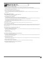
15 What to do if...
The Dr. STIKA PLUS doesn't function.
- Does the computer you're using provide the correct operating environment for the included software?
Check the conditions for the included software operating environment printed on the front cover of this manual and make sure that
the computer offers a suitable environment.
- Was the software installed using the setup program?
Be sure to use the setup program when installing the Dr. STIKA PLUS.
The setup program puts the files for each software package in the necessary locations to enable the software to be used under
Windows 95.
The STX-8/7 doesn't operate
- Is the STANDBY key on (with the STANDBY LED lit up)?
The power is off. Press the STANDBY key.
- Is the STANDBY LED not flashing?
<The LED flashes slowly (every 0.5 sec.) > (Only when using the STX-8)
This flashes when pen plotting has been selected for the driver and plotting is carried out. If this LED starts to flash, change the pen.
Refer to the relevant help screens for the driver for instructions on how to carry out pen plotting.
<The STANDBY LED is flashing rapidly (every 0.1 sec.) >
A communication error has occurred. Switch off the power and check the cable connections and port settings for the drivers.
- Is the cable connected?
Switch off the power to the computer and the STX-8/7, and use a parallel cable to connect the two devices.
- Is the correct type of cable used?
The type of parallel cable (printer cable) may vary according to the computer model. Make the connection with the correct type of cable
for the computer. Be sure the computer and the STX-8/7 are both switched off before attempting to attach or disconnect the parallel
cable (printer cable).
Uncut areas remain, or areas are not cleanly cut.
- Is the amount of blade extension correct?
The amount of blade extension that has been set is too short for the material being used. Increase the extended length of the blade to
the same thickness as the sheet portion.
- Is the blade broken?
Replace with a new blade.
The results of cutting are displaced, and uncut portions
- Is the amount of blade extension correct?
The amount of blade extension that has been set is too long for the material being used. Increase the extended length of the blade to
the same thickness as the sheet portion.
- Is the cutting speed correct?
The cutting speed is too fast. Change the driver setting to obtain a slower cutting speed. Please refer to the relevant help screens for
the driver to set the cutting speed.
- Has the material size been set correctly?
Material smaller than the set cutting range has been loaded. Load material that matches the cutting range.
- Pressing the STANDBY key does not switch off the power.
Unplug the AC adapter from the unit.
33
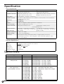
Specification
Main unit Specification
Max. cutting area
Acceptable sheet size
Cutting speed
Acceptable material
Control keys
LED
Interface
Power consumption
Acoustic noise level
External dimensions
Weight (unit only)
Operation temperature
Operation humidity
Accessories
STX-8
STX-7
250 mm (X) x 1000 mm (Y)
160 mm (X) x 1000 mm (Y)
(9-13/16" (X) x 39-5/16" (Y) )
(6-1/4" (X) x 39-5/16" (Y) )
Width: 280—305 mm (11"—12")
Width: 200—215 mm (7-13/16"—8-7/16")
Length: 1100 mm (43-1/4") or less
Length: 1100 mm (43-1/4") or less
12—40 mm/sec. (7/16"/sec.—1-9/16"/sec.)
PVC sheet (0.1 mm (0.00394") or less in thickness, 0.3 mm (0.0118") or less in thickness
including the backing board).
STANDBY key
STANDBY LED
Parallel (in compliance with the specification of Centronics)
Exclusive AC adapter (DC+12V 1.5 A)
Cutting mode: 50 dB (A) or less
Cutting mode: 47 dB (A) or less
(According to ISO 7779)
419 mm (W) x 147 mm (D) x 95.5 mm (H)
317 mm (W) x 147 mm (D) x 95.5 mm (H)
(16-1/2" (W) x 5-13/16" (D)) x 3-13/16" (H)) (12-1/2" (W) x 5-13/16" (D)) x 3-13/16" (H))
2 kg (4.4 lb.)
1.6 kg (3.5 lb.)
5—40°C (41—104°F)
35—80 % (no condensation)
Roland Software Package, Blade holder, Blade, AC adapter, Material for test cuts,
Applicationtape for test cuts, * Sheet setup guide, * Water based fiber tipped pen, * Paper,
STX-8/7 User's Manual
* Included only with the STX-8.
Interface Specification
[ Parallel ]
Standard
In compliance with the specification of Centronics
Input signal
STROBE (1BIT), DATA (8BIT)
Output signal
BUSY (1BIT), ACK (1BIT)
I/O signal level
TTL level
Transmission method
Asynchronous
Option Lists
Type
Cemented Carbide Blades
Adjustable Depth Blade Holder
Pressurized Oil Based
Ball-point Pen
Thick Water-based
Fiber Tipped Pens
(Line Thickness : 2.0 mm)
34
Model Nbr.
ZEC-U1002
XD-CH3
XD-BPHG
XD-3M-BLK
XD-3M-RED
XD-3M-BLU
XD-3M-GRN
XD-4SPA-WBG
XD-4SPB-WBG
XD-4SPC-WBG
XD-4SPD-WBG
XD-4SPE-WBG
XD-4SPF-WBG
XD-4SPG-WBG
XD-4SPH-WBG
XD-4SPI-WBG
XD-4SPJ-WBG
Contents
2 pcs./pkg
1 pcs./pkg
Holder (with one black refill for test)
Replaceable Refill 3 pcs./pkg, All Black
Replaceable Refill 3 pcs./pkg, All Red
Replaceable Refill 3 pcs./pkg, All Blue
Replaceable Refill 3 pcs./pkg, All Green
4 pcs./pkg, All Black
4 pcs./pkg, 1 Each Black, Red, Blue, Green
4 pcs./pkg, 1 Each Brown, Purple, Pink, Orange
4 pcs./pkg, All Red
4 pcs./pkg, All Blue
4 pcs./pkg, All Green
4 pcs./pkg, All Orange
4 pcs./pkg, All Pink
4 pcs./pkg, All Brown
4 pcs./pkg, All Purple
Please read this agreement carefully before opening the sealed
package or the sealed disk package
Opening the sealed package or sealed disk package implies your acceptance of the terms and conditions of this agreement.
If you do NOT accept this agreement, retain the package UNOPENED. (This product is just one of included items. Please
be aware that any amount of the purchase price will not be refunded for return of this product as a single item, regardless
of whether the package is opened or unopened.) The enclosed Roland product is a single user version.
Roland License Agreement
Roland DG Corporation ("Roland") grants you a non-assignable and non-exclusive right to use the COMPUTER
PROGRAMS in this package ("Software") under this agreement with the following terms and conditions.
1. Coming into Force
This agreement comes into force when you purchase and open the sealed package
or sealed disk package.
The effective date of this agreement is the date when you open the sealed package
or sealed disk package.
2. Property
Copyright and property of this Software, logo, name, manual and all literature
for this Software belong to Roland and its licenser.
The followings are prohibited :
(1) Unauthorized copying the Software or any of its support file, program module
or literature.
(2) Reverse engineering, disassembling, decompiling or any other attempt to
discover the source code of the Software.
3. Bounds of License
Roland does not grant you to sub-license, rent, assign or transfer the right granted
under this agreement nor the Software itself (including the accompanying items)
to any third party.
You may not provide use of the Software through time-sharing service and/or
network system to any third party who is not individually licensed to use this
Software.
You may use the Software by one person with using a single computer in which
the Software is installed.
4. Reproduction
You may make one copy of the Software only for back-up purpose. The property
of the copied Software belongs to Roland.
You may install the Software into the hard disk of a single computer.
5. Cancellation
Roland retains the right to terminate this agreement without notice immediately
when any of followings occurs :
(1) When you violate any article of this agreement.
(2) When you make any serious breach of faith regarding this agreement.
6. Limitations on Liability
Roland may change the specifications of this Software or its material without
notice.
Roland shall not be liable for any damage that may caused by the use of the
Software or by exercise of the right licensed by this agreement.
7. Governing Law
This agreement is governed by the laws of Japan, and the parties shall submit to
the exclusive jurisdiction of the Japanese Court.
R2-980828