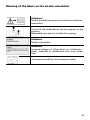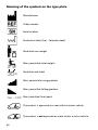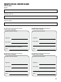
1
GB OPERATING MANUAL LIGHTWEIGHT WHEELCHAIRS Model-Family 1.7xx Model-Family 1.8xx We move people. Contents Introduction................................................................................................... 4 List of models................................................................................................ 5 Indications...................................................................................................... 5 Acceptance..................................................................................................... 5 Specifications................................................................................................. 6 Use.................................................................................................................. 6 Adjustment.................................................................................................... 7 Life span......................................................................................................... 7 Overview........................................................................................................ 8 Brake............................................................................................................... 9 Pressure brake - user.............................................................................................9 Locking the brakes...........................................................................................9 Releasing the brakes........................................................................................9 Brake lever extension..........................................................................................10 Leg supports................................................................................................ 11 Calf belt................................................................................................................11 Removing the calf belt..................................................................................11 Attaching the calf belt...................................................................................11 Length adjustment of the calf belt..............................................................11 Leg support lower part.......................................................................................12 Footplates.......................................................................................................12 Footboard.......................................................................................................13 Leg support upper part.......................................................................................14 Turning the leg supports to the side ...........................................................14 Swivelling in the leg supports.......................................................................14 Removing the leg supports...........................................................................15 Attaching the leg supports...........................................................................15 Height adjustment of the leg support.........................................................16 Leg supports for amputees.................................................................................17 Angle adjustment of the amputee leg support..........................................17 Arm supports............................................................................................... 18 Removing the arm supports...............................................................................18 Inserting the arm support.............................................................................19 Height adjustment of the arm supports............................................................20 2 Back support................................................................................................ 21 Back support with angle adjustment 30°..........................................................21 Push handles................................................................................................ 22 Wheels.......................................................................................................... 24 Drive wheels........................................................................................................24 Quick release axle..........................................................................................24 Tyre damage on pneumatic tyres.......................................................................24 Specialities for double handrims........................................................................25 Propelling the wheelchair.............................................................................25 Folding/unfolding with double handrims....................................................25 Support castors........................................................................................... 26 Support castor length:........................................................................................26 Stick-in support castors.......................................................................................26 Removing/inserting the support castors......................................................26 Swing-out support castors..................................................................................27 Swinging the support castors........................................................................27 Retaining strap............................................................................................ 27 Transport of people inside a motor vehicle............................................. 28 Securing the wheelchair.....................................................................................28 Maintenance................................................................................................ 28 Maintenance........................................................................................................28 Maintenance schedule........................................................................................29 Technical data.............................................................................................. 32 Meaning of the labels on the electric wheelchair............................................39 Meaning of the symbols on the type plate.......................................................40 Inspection certificate.................................................................................. 41 Warranty / Guarantee.................................................................................. 42 Inspection certificate for transfer......................................................................43 3 INTRODUCTION We thank you for the confidence you have placed in our company by choosing a wheelchair from this series. With all equipment and their accessories the wheelchair offers die respective adaptation to your disability. Like any other vehicle, a wheelchair is a technical aid. It is subject to explanations, requires regular care and can cause danger when used improperly. The correct handling must therefore be learned. This operating manual is to help you get accustomed to the handling of the wheelchair as well as to prevent accidents. ☞Note: Please note that the illustrated equipment variants can deviate from your model. We have therefore also listed chapters with options that might not be applicable for your individual wheelchair. Attention: Read and observe the following documentation belonging to the wheelchair before first operation: ! – this operating manual, – Safety and general handling instructions < Mechanical and muscle powered wheelchairs >. ☞Note: 4 Children and juveniles should read the documentation belonging to the wheelchair together with their parents respectively a supervisor or an accompanying person before first use. For users with visual impairments the PDF-files of the above mentioned documents can be accessed on our website < www.meyra-ortopedia.com >. ☞Contact your specialist dealer when required. Alternatively users with visual impairments can have the documentation read out by a helper. LIST OF MODELS ACCEPTANCE This operating manual applies to the following models: All products are checked for faults in the factory and packed in special boxes. Model-Family 1.7xx Model 1.750 Model 1.751 Model 1.760 ☞Note: Model-Family 1.8xx Model 1.840 Model 1.850 INDICATIONS However, we request that you check the vehicle for possible transport damage immediately on receipt – preferably in the presence of the carrier. ☞Note: The packaging of the wheelchair should be stored for a further transport that might become necessary. If the following indications occur we recommend the application of this mobility product: ☞Walking disability resp. extremely limited walking ability as part of the basic need to move around in your own home. ☞The need to be able to leave home for a short walk in fresh air or in order to reach the places, commonly in the perimeter of the home, required to fulfil basic needs. 5 SPECIFICATIONS USE The wheelchair of the lightweightfamily, was developed for adults and adolescents. Through its constructive advantages the wheelchair can universally be implemented on level, firm surfaces and is therefore an allround-wheelchair: The wheelchair solely serves to transport one person in the seat and not as a hauling aid, transporter or similar. – for indoors (e.g. apartment, day care), – outdoors (e.g. in parks), – as a companion on tours (e.g. in a bus or train). The wheelchair offers manifold adjustment possibilities to individual vital statistics. The wheelchair should be adapted to your needs by a specialist dealer before the first use. The adaptation will take into account the driving experience, the physical limits of the user and the main place of use of the wheelchair. Attention: Always have adaptation and adjustment work carried out by a specialist dealer. ! 6 ADJUSTMENT LIFE SPAN The specialist workshop will hand out the wheelchair to you under consideration of all relevant safety instructions, ready for operation and adjusted to your needs. We expect an average lifespan of about 4 years for this product, as far as the product is applied for its designated purpose and all maintenance and service guidelines. ☞Note: ☞We recommend a regular control The life span of your product depends upon the frequency of use, the application environment and care. if the wheelchair adjustment in order to ensure a long-term optimal provision even with changing illness/handicap patterns of the user. Especially for children and juveniles an adjustment every 6 months is recommendable. ☞We recommend regular medical The implementation of spare parts can prolong the life span of the product. As a rule spare parts are available up to 5 years after production is discontinued. ☞The indicated life span does not constitute additional guarantee. exams in order to ensure safety for active participation in traffic. ☞Retrospective adjustments should be carried out solely by the specialist dealer! 7 OVERVIEW The overview shows, representative for all models, the most important components of the wheelchair. 1 2 4 3 5 12 6 11 10 9 8 7 Pos. Description Pos. Description 7 8 9 10 11 12 8 1 2 3 4 5 6 Push handle Back support Arm support Clothes guard Seat belt / seat cushion Locking lever, leg support Foot board/footplates divided Steering wheel Drive wheel Brake lever – pressure brake Handrims Locking knob – Quick release axle BRAKE By locking the brakes with the brake lever (1), the wheelchair is secured against rolling away unintentionally (parking brake). 1 Depending on the version, the wheelchair can be equipped with pressure brakes (2) or with drum brakes (3). 2 ☞Note: Therefore observe the maintenance instructions as well as safety and general handling instructions < Mechanical and muscle powered wheelchairs > chapters < General safety information > and < Brakes >. Attention: Arrange an immediate repair of the brakes by your specialist workshop if the braking performance reduces. ! 3 4 Pressure brake - user Locking the brakes To secure the wheelchair against any unintentional rolling, press both brake levers forward all the way (4). ☞Note: It should not be possible to push the wheelchair forward when both brakes are locked. Releasing the brakes ☞Note: If needed use suitable gloves in order to brake down the wheelchair. Pull both brake levers back all the way (1). Operating brake The wheelchair is braked down with help of the handrims. 9 Brake lever extension The brake lever extensions multiply the applied brake force and reduce the force you need to apply in order to lock the brakes (1). Attention: Do not use the grips of the brake lever as support ! ! • 10 Do not pull off the brake lever extension whilst in motion. – Accidents could result if the brake lever extension is drawn too much! 1 LEG SUPPORTS Attention: Before any actions on the leg supports the wheelchair is to be secured against unintentional rolling motions. – View chapter < Brakes >. ! Calf belt 1 2 The removable calf belt (1) prevents the feet from sliding off the back of the footplates. For attachment the calf belt is guided through the upper leg supports (2) or around special receptacle pins (3) and adjusted to the corresponding length with the Velcro straps. Attention: Never drive without calf belt (except when shuffling)! – Danger of accidents! ☞Note: The leg strap is omitted for height adjustable leg supports and is replaced by a leg padding. ☞The calf belt must be removed in order to swivel away the leg supports. ! 3 Length adjustment of the calf belt For length adjustment the calf belt is adjusted in corresponding length with help of the velcro fastener. Removing the calf belt For removal the calf belt is pulled from the attachment pins (2) after opening the velcro fastener. Attaching the calf belt For attachment both loops of the calf belt are slid over the attachment pins [3] and attached with the velcro fastener [4]. 11 Leg support lower part The footplates are to be folded up for entry into, exiting the wheelchair or scuttling (moving the wheelchair with help of the feet) [1]. ☞Check the locking points! – Remove both feet from the footplates. 1 – Remove lower calf belt, if present. ☞Hereto observe chapter < Calf belt >. ☞Note: Before starting to drive the footplates are to be folded down again [2] and the calf belt attached. Footplates The footplates can be folded outward and up [1] resp. inward and down [2]. 12 2 Footboard The footboard [1] can be folded up to one side. ☞Note: Fold the footboard up before swivelling away and removing the upper leg support. Folding up the footboard 1 In order to fold up the footboard lift the loose end of the footboard (2) as far as possible. Folding the footboard down In order to fold down the footboard, lower the loose end of the footboard as far as possible down onto the footboard bracket [5]. ☞Note: After folding down the footboard do not forget to check whether it has locked into place (4). 2 4 5 13 Leg support upper part The upper leg support with an inserted lower leg support is termed leg support. Turning the leg supports to the side For easy transfer out of/into the wheelchair as well as driving closer to a closet, bed or bathtub the leg supports can be swivelled away toward the in-/outside (1). 1 ☞Note: Before removing the leg supports remove the calf belt and fold the footplates up. ☞View chapter < Calf belt > and chapter < Lower leg support >. 2 2 Attention: Leg supports turned to the side are released automatically and can easily come off. Note this when handling (e.g. transport). ! – Pull or press the respective locking lever (2) backward and swivel the corresponding leg support outward. Swivelling in the leg supports For inward swivelling, let the leg supports swivel forward until the lock audibly engages [3]. ☞Note: After audibly swivelling the leg supports inward check the respective locking device. ☞Afterwards observe chapter < Lower leg support >. 14 3 Removing the leg supports For easy transfer into and out of the wheelchair as well as a reduced wheelchair length (important for transport) the leg supports can be removed [1]. ☞Note: Before removing the leg supports loosen or remove the calf belt on one side. ☞View chapter < Calf belt >. 1 First swivel the leg support sideways [2] and then remove them toward the top. ☞Therefore observe chapter < Swivelling away leg supports >. Attaching the leg supports With the leg support in a swivelledaside position, hang it in and then swivel it to the front until the locking device audibly latches. 2 ☞Note: After attachment swivel the leg supports inward. ☞Therefore observe chapter < Swivelling in the leg supports >. Press the leg supports, swivelled to the side, parallel to the front frame tube and lower it into place [2]. – In doing so the holding pin must slide into the frame tube. 15 Height adjustment of the leg support Attention: Never put the free hand into the adjustment mechanism while adjusting the height adjustable leg support. – Danger of crushing! ! • Have the leg support secured by an accompanying person against unintentionally falling down. Lifting/lowering the leg support 1. Before lifting/lowering relieve the leg support by an accompanying person by slightly lifting it up. 2. Afterwards loosen the clamping lever (1) and have the leg support lifted/lowered slowly to the desired level by an accompanying person. Attention: Do not let the leg support drop on its own weight. – Danger of injury! ! 3. After the adjustment retighten the clamping lever (1) securely. 16 1 Leg supports for amputees ☞Hereto observe chapter < Leg support upper part >. Attention: Never put the free hand into the adjustment mechanism while adjusting the amputee leg support. – Danger of crushing! ! • 1 Have the amputee leg support secured by an accompanying person against unintentionally falling down. Angle adjustment of the amputee leg support – For angle adjustment of the amputee leg support first loosen the clamping lever (1) until the toothing is loose. – Afterwards lift/lower the amputee leg support to the desired height and retighten the clamping lever (2). ☞In doing so ensure that the toothing of the angle adjustment grips into place. 17 ARM SUPPORTS The arm supports [1] can (depending on equipment) be removed, are height adjustable and at the same time serve as a padded arm support, clothes guard and wind protector. Attention: No not grab between the frame and arm support. – Danger of jamming! ! • Do not lift the wheelchair using the arm supports. • The wheelchair should only be used with the arm supports assembled! • When the wheelchair is being pushed by an accompanying person the user is to place his hands onto the arm cushions or in his lap and not at the sides between body and arm support. – Danger of squashing the fingers! 1 2 ☞To transfer into/out of the wheelchair the arm support can be swivelled backward. Removing the arm supports To remove the arm supports, first pull the locking lever (2) over to the top. Afterwards swivel the arm support up toward the back and then remove it toward the top [3]. 18 3 Inserting the arm support According to model and design: – First insert the arm support beside the seat surface from the top into the guide (1). – Then press the arm support down and lower the locking lever (2). ☞Note: 2 1 The rear fitting hook (3) or tube of the arm support (4) has to lie in the guide groove on the back. 3 3 19 Height adjustment of the arm supports Version 1: – Pull the padded arm support up to the desired height [1]. – To lower the padded arm support, pull the locking lever (2) over to the top. 1 – Push the padded arm support down to the required height. – For locking, swivel the lever (2) back down. Version 2: – Hold onto the padded arm support with one hand. – To lift or lower the padded arm support press the locking button (3) down with the other hand. 2 – Then slide the padded arm support to the desired height and release the locking button (3). – Afterwards slide the padded arm support again until it audibly locks into place (3). ☞Check the locking device by trying to pull or push the padded arm support. 20 3 BACK SUPPORT On some models we offer angle adjustable back supports (1). – Increase of mobility of the upper body, as well as reduced wheelchair height (important when stowing the wheelchair) through the foldable back support. 2 1 – Pressure relief for buttocks muscles (decubitus prophylactics). – Relief for the spinal column. – Fatigue-free sitting. – Comfortable rest position in combination with height adjustable leg supports. Back support with angle adjustment 30° The back support can be reclined in three positions of each 10°. – Pull both levers (2) up and adjust the back support to the desired angle. – After the adjustment release both levers and let the back support lock into place. Attention: After the adjustment make sure that the back support has locked into place. – Danger of injury! ! 21 PUSH HANDLES The height adjustable push handles are about 30 cm continuously height adjustable, turnable in steps of 30° and secured against being pulled out. Push handles with clamping device 1 ☞In doing so, hold onto the push handle that is to be adjusted with one hand. Height adjustment: 1. Loosen the clamping screw with the handwheel or clamping lever (2) so far that the respective push handle can be adjusted into the desired position. 2 Angle adjustment: 1. In order to turn the push handles, loosen the clamping screws with the handwheel or clamping lever (2) or pull out the push handle and reinsert it in the desired position. Extracting/inserting: 1. Press down the respective spring button (3) in order to extract or insert the push handles. 3 2. Afterwards retighten the clamping screw with the handwheel or clamping lever (2). Special features of the clamping lever The clamping lever (2) can be turned into an operation position that is comfortable for you. – For this pull the clamping lever (2) outward (direction of the arrow), until the teething is released. 22 – After turning the clamping lever (2) let the teething snap back into place. Height adjustable push handles with tube guide The push handles (1) are guided swivel-proof inside the back tube and steplessly height by up to 10 cm. Height adjustment: ☞In doing so, hold onto the push handle that is to be adjusted with one hand. 1 1. Swivel the respective clamping lever (2) with one hand into the horizontal position. 2. Adjust the push handle to the desired height and clamp it tight. – For this swivel the clamping lever downward (1). Attention: After each adjustment the secure fit of the push handles is to be checked with a pull-/push test! ! 2 ☞Note: With the clamping lever swivelled down, the respective push handle may not let itself be moved. 23 WHEELS Drive wheels The drive wheels are mounted on a fixed axle (1) or on a quick release axle (2). ☞Note: The air pressure value for the tyres of the wheelchair can be read in the < Technical data > or details on both sides of the tyre cover. 1 ☞If the drive wheels has too much sideward lag or the quick release axle does not engage, contact your specialist dealer immediately for repair. 3 ☞No person may be seated in the wheelchair during assembly or removal. The wheelchair should stand on a level and firm surface. Before starting the disassembly of a wheel, support the frame to prevent the wheelchair from tipping over and secure it to prevent an unwanted movement or tipping over. Quick release axle The drive wheels can be removed and reassembled without any tools. – First press the locking button (3) of the quick release axle in the center of the hub. – Afterwards remove or attach the drive wheel. Attention: After inserting the drive wheel the locking button (3) must stick a couple of millimetres out of the wheel nut. ! 24 2 Tyre damage on pneumatic tyres ☞For repairing tyre damage we recommend the use of a foam cartridge that is available in speciality shops. – Afterwards look up a specialist workshop as soon as possible. Specialities for double handrims The wheelchair can be propelled with on hand with the double handrim (1). Attention: Before each ride ensure the secure fit of the connection rod (2)! ! 1 Propelling the wheelchair Both handrims are to be operated simultaneously to drive straight forward. A curve can be driven by operating only one handrim. Folding/unfolding handrims with 2 3 double ☞Therefore also observe chapter < Folding/unfolding >. The telescopic connector tube (2) is to be removed before beginning the folding procedure. – In order to remove the connection tube (2) the clamping screw is to be loosened through the handwheel (3). After unfolding the wheelchair the telescopic connection tube (2) is to be replaced and the clamping screw retightened with the handwheel (3). 25 SUPPORT CASTORS Code 691 To increase tilting stability each side can be equipped with one bent tubing with two small wheels which can be inserted into the lower frame tubing from the rear (1). 2 1 Support castor length: The support castors must protrude beyond the drive wheels, identically on both sides, by at least their diameter in order to have an adequate anti-tip function. To achieve sufficient tilting stability, both support castors should be positioned parallel to each other. – Danger of accidents by overturning to the side! Attention: Support castors do not provide sufficient protection against tipping over in certain situations. ! Stick-in support castors The insertable support castors can be inserted from the back into the lower frame tubes (1). Removing/inserting the support castors – Depress the spring button (2) in order to remove/insert a support castor. 26 Swing-out support castors The support castors (1) can be swivelled inward underneath the seat (2). ☞Swivelling of the support castors can be done by an accompanying person or aid. – Free foot space for the accompanying person with the support castors swung inwards. 1 Swinging the support castors ☞Note: This function can be performed with the foot. Press the support castors down out of the lock then swivel them forward under the seat ( 2), respectively toward the back (1) until the lock engages automatically. 2 RETAINING STRAP The retaining strap [3] is screwed from the back onto the respective back support tube. ☞ Note: The retrospective assembly of a retaining strap is only to be carried out by a specialist workshop! 3 Attention: The retaining strap is not part of the retaining system for the wheelchair and/or user during transport in a handicapped transport vehicle. ! 27 TRANSPORT OF PEOPLE INSIDE A MOTOR VEHICLE To determine if your wheelchair is approved as a seat for person transport inside a motor vehicle, please look at the type plate of your wheelchair. 1 2 Attention: Subsequently, firmly attached parts of non-original parts to your wheelchair are not approved for person transportation within a motor vehicle. ! Securing the wheelchair The wheelchair is only to be secured through the four securing points (1) and (2). ☞The anchor positions are marked with the symbol (3). ☞The procedure for securing the wheelchair can be read in the document < Safety and general handling instructions Mechanical and muscle powered wheelchairs > chapter < Transport in motor vehicles or conveyors >. MAINTENANCE An incorrect or neglected cleaning and maintenance results in a limitation of the product liability. Maintenance The following maintenance schedule gives you a guide for carrying out the maintenance. 28 3 ☞They do not give information about the actual extent of work required on the vehicle. Maintenance schedule WHEN WHAT REMARK Before starting out Test brakes for faultless operation Carry out test yourself or with a helper. Activate brake lever to the limit. The locked wheels should not be able to turn under operating conditions. If they can still turn, the brakes must be repaired by an authorised specialist workshop. Before starting out Check pressure brake for wear Move brake lever to the side Before starting out Check air pressure of the tyres Carry out tests yourself or have a helper do it. If you notice any increasing slackness on the brake lever take the wheelchair to your specialist workshop immediately for repairs. – Danger of accident! Do it yourself or with the aid of a helper. Use a tyre pressure tester or, if not available, the 'thumb press' method or similar (view < Safety- and general handling instructions Mechanical and muscle powered wheelchairs > chapter < Tyres > ). 29 WHEN WHAT REMARK Before starting out Check tyre profile Carry out visual check yourself. If the tyre profile is worn down or if the tyre is damaged, consult a specialist workshop for repairs. Before starting out Check back support for stability Carry out the test yourself or by a helper. If deformations or cracks occur in the welding seams, contact a specialist workshop immediately for repairs. – Danger of accidents! Check frame tubes for damage Before starting out Especially before driving in the dark Check the lighting Every 8 weeks (depending on tance covered) Lubricate the following components with a few drops of oil dis- Check the light- and indicator signal equipment as well as reflectors for immaculate performance. – Bearing brace. of cross- – Moving parts of the locking mechanism. – Brake lever bearings. 30 Carry out test yourself or with a helper. Do it yourself or with the aid of a helper. Components must be free from used oil residues before lubrication. Please ensure that excess oil does not contaminate the environment (e.g. your clothing). WHEN Every 8 weeks (depending on tance covered) dis- WHAT REMARK Check all screw connections for secure fit Carry out test yourself or with a helper The following is to be checked with great care: – Attachment of the back- and seat profiles at the side frame, – attachment of the footplate to the side frame. Every 6 months (depending on quency of use) Check fre- – Cleanness. – General condition. View < Maintenance > in document < Safetyand general handling instructions Mechanical and muscle powered wheelchairs >. Do it yourself or with the aid of a helper. Manufacturer recommendation: Every 12 months (depending on frequency of use) Safety inspection – Vehicle To be carried out by the specialist dealer. 31 TECHNICAL DATA Tyre filling pressure: All model dependent specifications within the < Technical data > refer to the standard version of the respective models. Full tyre pressure – steering wheel The overall length depends on the position and size of the drive wheels. If not noted otherwise the dimensions are determined with drive wheels of ø 610 mm (24“). The widths were determined with a handrim distance of 15 mm. Dimensional tolerance ± 1 cm, ± 2°. Short form of wheelchair dimensions: SH = Seat height SW = Seat width SD = Seat depth BH = Back support height Calculation of the max. user weight: Attention: The permissible total weight is calculated from the empty weight of the wheelchair and the maximum user- (person-) weight. ! Additional weight due to subsequent additions or luggage reduce the maximum permissible user weight. Example: A driver wishes to take luggage with a weight of 5 kg. Thus, the maximum user weight is reduced by 5 kg. 32 Maximum tyre pressure is printed on the tyres on each side. Standard: 2.5 - 3.5 bar = 36 - 50 psi Full tyre pressure – drive wheel Standard: 3.0 - 4.0 bar = 44 - 58 psi Ultra-light running tyres: 6 bar = 87 psi High pressure: 8 bar = 116 psi Model:......................................................... 1.750 / 1.751 / 1.760 Type plate:............................................................................... at the crossbrace tube Life span:........................................................................................................... 4 years Dimensions Overall length (with leg supports): Model 1.750 / 1.751:........................................................ min. 1000 / max. 1040 mm Model 1.760:.................................................................... min. 1000 / max. 1070 mm Length without leg supports:............................................. min. 740 / max. 780 mm Overall width: Model 1.750:........................................................................ min. 560 / max. 740 mm Model 1.751:........................................................................ min. 560 / max. 690 mm Model 1.760:........................................................................ min. 680 / max. 860 mm Overall height on rear seat height 51.5 cm / back support height 42 cm:.......................... 960 mm Back strap height adjustable by +2.5 cm each: Model 1.750..........................................................................................40 / 42 / 44 cm Model 1.751.................................................................................................40 / 42 cm Model 1.760.................................................................................................42 / 44 cm Seat width Model 1.750...................................................... 38 / 40 / 43 / 46 / 48 / 50 / 53 / 56 cm Model 1.751.....................................................................38 / 40 / 43 / 46 / 48 / 51 cm Model 1.760...................................................................................50 / 53 / 58 / 68 cm Seat depth: Model 1.750 / 1.751..............................................................................40 / 43 / 46 cm Model 1.760.................................................................................................43 / 46 cm Seat height, without cushion (seat surface height at front edge): Model 1.750............................... 39 / 40 / 42 / 43 / 43.5 / 45 / 47 / 48.5 / 50 / 51.5 cm Model 1.751.................................................................................42.5 / 47.5 / 51.5 cm Model 1.760.................................................... 43 / 43.5 / 45 / 47 / 48.5 / 50 / 51.5 cm Arm support height from seat surface:............................................................23 cm Back support to front edge of arm support:........................... min. 28 / max. 34 cm Seat cushion thickness:....................................................................................3 / 6 cm Push handle height (only for BH 40 / 42): Code 502 (steplessly adjustable):.......................................................................18 cm Back support angle:................................................................................................ 90° 33 Seat inclination: Model 1.750 / 1.760:......................................................................... min. 0° / max. 4° Model 1.751:.....................................................................................................min. 4° Manufacturer setting............................................................................................... 4° Leg support angle:................................................................................................ 111° Foot support to seat, without seat cushion (lower shank length): with leg supports code 808:...................................................... min. 35 / max. 52 cm with foot board code 54:.......................................................... min. 35 / max. 52 cm Wheels Steering wheel: ø 100 mm:................................................................................................. solid rubber ø 125 mm:................................................................................................. solid rubber ø 142 mm:..........................................................................................soft solid rubber ø 178 mm (7"):......................................................................................... solid rubber ø 178 mm (7 x 1 3/4") polyurethane foam:.........................................puncture safe ø 178 mm (7 x 1 3/4") pneumatic tyres:.......................................................... 2.5 bar Drive wheel: ø 559 mm (22 x 1“) pneumatic tyres:.............................................................. 4.0 bar ø 610 mm (24 x 1“) pneumatic tyres:.............................................................. 4.0 bar ø 559 mm (22 x 1 3/8“) polyurethane foam:.......................................puncture safe ø 610 mm (24 x 1 3/8“) polyurethane foam:.......................................puncture safe Handrim diameter:.............................................................. min. 48.5 / max. 53.5 cm Axle: Horizontal position:....................................................................min. 0 / max. 45 mm Transport dimensions Folding length (with leg supports): Model 1.750 / 1.751:........................................................ min. 1000 / max. 1040 mm Model 1.760:.................................................................... min. 1000 / max. 1070 mm Length without leg supports, drive wheels:................................................. 610 mm (Support castors are removed or swivelled underneath the seat) Folding width:....................................................................... min. 280 / max 310 mm Folding height:........................................................................................min. 960 mm 34 Permitted inclination/slopes max. obstacle height (depending on the setting of the leg support height):. 0 to 100 mm Minimal turning radius: .............................................................................. 1250 mm Max. permissible rising gradient:............................................................... 4.5° (8 %) Max. permissible falling gradient:.............................................................. 4.5° (8 %) Max. permissible transverse gradient:....................................................... 4.5° (8 %) static tilting safety in all directions:............................................................ 6° (10 %) Climatic data: Ambient temperature:..................................................................... -25 °C to +50 °C Storage temperature:........................................................................ -40 °C to +65 °C Weights permissible total weight Model 1.750:............................................................................................ max. 136 kg Model 1.751:............................................................................................ max. 137 kg Model 1.760:............................................................................................ max. 176 kg Model 1.760 reinforced version:............................................................. max. 220 kg max. user weight (including additional load): Model 1.750 / 1.751:......................................................................................... 120 kg Model 1.750 transport in a HTV:..................................................................... 100 kg Model 1.760:..................................................................................................... 160 kg Model 1.760 reinforced version:............................................................. max. 200 kg max. additional loading:.....................................................................................10 kg Empty weight: Model 1.750 / 1.760:............................................................................................16 kg Model 1.751:........................................................................................................17 kg Model 1.760 reinforced version:............................................................... max. 22 kg heaviest single component:................................................................................10 kg heaviest single component reinforced version:................................................16 kg Transport weight:......................................................................................... min. 9 kg (without leg supports, arm supports, cushion, drive wheels 35 Model:..................................................................... 1.840 / 1.850 Type plate:............................................................................... at the crossbrace tube Life span:........................................................................................................... 4 years Dimensions Overall length: with leg supports:............................................................ min. 1020 / max. 1090 mm without leg supports:..................................................................................... 775 mm With the driving wheel position in the rear, the length is extended by 70 mm. Overall width:...................................................................... min. 560 / max. 680 mm with arm support Code 70 / 77 / 78 / 101 / 107:.................................. SW + 180 mm with arm support Code 16 / 20 / 81 / / 82:........................................... SW + 220 mm Overall height Model 1.840:........................................................................ min. 920 / max. 950 mm Model 1.850:........................................................................ min. 750 / max. 980 mm Height of back support: each adjustable by +2.5 cm...........................................................35 / 38 / 42 / 45 cm Seat width:..............................................................................38 / 40 / 43 / 48 / 50 cm Seat depth:............................................................................................40 / 43 / 46 cm With a seat depth of 46 cm the length is extended by 3 cm. Seat height variable, without cushion (seat surface height at front edge): Model 1.840:........................................................................ min. 390 / max. 470 mm Model 1.850:........................................................................ min. 420 / max. 530 mm Arm support height from seat surface:............................................................23 cm Back support to front edge of arm support:........................... min. 28 / max. 34 cm Seat cushion thickness:....................................................................................3 / 6 cm Push handle height: Code 502 (steplessly adjustable):.......................................................................18 cm Back support angle:................................................................................................ 90° Seat inclination:................................................................................ min. 0° / max. 4° Manufacturer setting............................................................................................... 4° Leg support angle:................................................................................................ 111° 36 Foot support to seat, without seat cushion (lower shank length): Model 1.840:.............................................................................. min. 35 / max. 46 cm Model 1.850:.............................................................................. min. 38 / max. 52 cm Wheels Steering wheel: ø 125 mm:................................................................................................. solid rubber ø 142 mm:..........................................................................................soft solid rubber ø 150 x 27 mm, polyurethane foam:....................................................puncture safe ø 178 mm (7 x 1 3/4") pneumatic tyres:.......................................................... 2.5 bar ø 203 mm (8"):......................................................................................... solid rubber Drive wheel: ø 559 mm (22 x 1“) pneumatic tyres:.............................................................. 4.0 bar ø 610 mm (24 x 1“) pneumatic tyres:.............................................................. 4.0 bar ø 559 mm (22 x 1 3/8“) polyurethane foam:.......................................puncture safe ø 610 mm (24 x 1 3/8“) polyurethane foam:.......................................puncture safe Handrim diameter: Model 1.840:........................................................................ min. 43.5 / max. 53.5 cm Model 1.850:........................................................................ min. 48.5 / max. 53.5 cm Axle: Horizontal position:.............................................................. min. +35 / max. -35 mm Transport dimensions Folding length (with leg supports):............................... min. 1020 / max. 1090 mm Folding length without leg supports, drive wheels:......... min. 560 / max. 680 mm (Support castors are removed or swivelled underneath the seat) Folding width: with arm support Code 70 / 77 / 78 / 101 / 107:............................................ 280 mm with arm support Code 16 / 20 / 81 / 82:....................................................... 320 mm Folding height: Model 1.840:........................................................................ min. 920 / max. 950 mm Model 1.850:........................................................................ min. 485 / max. 535 mm 37 Permitted inclination/slopes max. obstacle height (depending on the setting of the leg support height):........................0 to 100 mm Minimal turning radius: .............................................................................. 1250 mm Max. permissible rising gradient:............................................................... 4.5° (8 %) Max. permissible falling gradient:.............................................................. 4.5° (8 %) Max. permissible transverse gradient:....................................................... 4.5° (8 %) static tilting safety in all directions:............................................................ 6° (10 %) Climatic data: Ambient temperature:..................................................................... -25 °C to +50 °C Storage temperature:........................................................................ -40 °C to +65 °C Weights permissible total weight Model 1.840:............................................................................................ max. 135 kg Model 1.850:............................................................................................ max. 165 kg max. user weight (including additional load): Model 1.840:..................................................................................................... 120 kg Model 1.850:..................................................................................................... 150 kg max. additional loading:.....................................................................................10 kg Empty weight: Model 1.840:........................................................................................................15 kg Model 1.850:........................................................................................................15 kg heaviest single component:..................................................................................9 kg Transport weight:......................................................................................... min. 9 kg (without leg supports, arm supports, cushion, drive wheels 38 Meaning of the labels on the electric wheelchair Attention! Read the operating manuals and other provided documentation. Do not lift the wheelchair at the arm supports or leg supports. Removable parts are not suitable for carrying. Attention Readjust the brakes. Attention Increased danger of tilting when on inclinations / slopes, especially in combination with short wheel base. Attachment possibility of the transport safety. 39 Meaning of the symbols on the type plate Manufacturer Order number Serial number Production date (Year – Calendar week) Permitted user weight Max. permissible total weight Permitted axle loads Max. permissible rising gradient Max. permissible falling gradient Max. permitted final speed The product is approved as a seat within a motor vehicle. X 40 The product is not approved as a seat within a motor vehicle. INSPECTION CERTIFICATE Vehicle data: Model: Delivery note no.: Serial-no. (SN): Recommended safety inspection 1st year (at least every 12 months) Recommended safety inspection 2nd year (at least every 12 months) Stamp of specialist dealer: Stamp of specialist dealer: Signature: Signature: Place, date: Place, date: Next safety inspection in 12 months Next safety inspection in 12 months Date: Date: Recommended safety inspection 3rd year (at least every 12 months) Recommended safety inspection 4th year (at least every 12 months) Stamp of specialist dealer: Stamp of specialist dealer: Signature: Signature: Place, date: Place, date: Next safety inspection in 12 months Next safety inspection in 12 months Date: Date: 41 WARRANTY / GUARANTEE We accept legal liability for this product within the scope of or general terms and conditions and warranty and the guarantee according to our described quality service. For warranty and guarantee demands please contact your specialist dealer with following Warranty/Guarantee section and the there included information on model description, delivery note number with delivery date and serial number (SN). The serial number (SN) can be read off of the type plate. Precondition for the acceptance of liability in any case is the intended use of the product, the use of original spare parts by specialist dealers as well as maintenance and inspections in regular intervals. Interferences through radiation sources such as mobile phones with high transmission power, HiFi-equipment and other extreme interference radiators outside of norm specifications cannot be declared as warranty or guarantee claims. Attention: Failure to observe the instructions in the operating manual, improperly carried out maintenance work and, especially, technical changes and additions (add-ons) carried out without our prior consent will lead to a general loss of guarantee and product liability. ! ☞ Note: This operating manual as a part of the product is to be handed out in case of a change of user or owner. We reserve the right to make technical improvements. Guarantee is not granted for surface damages, tyres of the wheels, damages due to loosened screws or nuts as well as worn out attachment holes due to frequent assembly work. Furthermore, damage to the drive and electronics caused by improper cleaning using steam cleaning equipment or the deliberate or accidental flooding of the components are also excluded. The product conforms with the EC Directive 93/42/EEC (MDD) for medical products. 42 WARRANTEE / GUARANTEE SECTION Please fill out! Copy if necessary and send the copy to the specialist dealer. Warranty / Guarantee Model designation: Delivery note no.: SN (view type plate): Date of delivery: Stamp of the specialist dealer: Inspection certificate for transfer Vehicle data: Serial-no. (SN): Model: Stamp of specialist dealer: Signature: Place, date: Delivery note no.: Next safety inspection in 12 months Date: 43 Your specialist dealer: We 44 move people. MEYRA-ORTOPEDIA Vertriebsgesellschaft mbH Meyra-Ring 2 · D-32689 Kalletal-Kalldorf P.O. Box 1 703 • D-32591 Vlotho Fon +49 (0)5733 922-311 Fax +49 (0)5733 922-9311 [email protected] www.meyra-ortopedia.de 205 303 001 • (Status: 2011-08) All technical modifications reserved!