1
V1
User's Manual
Version 4.16v
(11/2002)
For use with:
V1 Disk Recorder Series
w/ Silver Front Panel and firmware up to 4.16
Doremi Labs, Inc.
306 E. Alameda Avenue, Burbank, CA 91502
USA
2
TABLE OF CONTENTS
WARRANTY............................................................................................................................... 4
WARNING................................................................................................................................... 5
AVIS ............................................................................................................................................. 5
PROTECTING YOURSELF AND THE V1 ............................................................................ 5
CE NOTICE ................................................................................................................................ 7
INTRODUCTION....................................................................................................................... 8
DESIGN OF MANUAL ............................................................................................................ 10
1
SETUP GUIDE................................................................................................................... 11
1.1
Quick Start Guide for V1 DCT and MPEG2 machines........................................... 11
1.2
Instructions for Initial Setup and Transport ........................................................... 12
1.3
Setup of one or more drives on V1 DCT and MPEG2 ............................................ 12
1.4
Setup of drives on the V1-U and V1-UHD .............................................................. 13
1.5
Single File System (SFS) Versus Multi-File System (MFS)..................................... 13
2 FRONT PANEL DESCRIPTION ........................................................................................... 14
2.1
Keypad Area............................................................................................................ 14
2.2
Menu Controls and Jog/Shuttle............................................................................... 15
2.3
Transport Controls.................................................................................................. 17
2.4
LCD Time Code Display ......................................................................................... 17
2.5
SCSI Drives ............................................................................................................. 18
2.6
LCD Video Display ................................................................................................. 19
3 REAR PANEL DESCRIPTION ............................................................................................. 20
3.1
Video Inputs / Outputs >>DCT, MPEG2 & Uncomp SD ....................................... 22
3.2
Video Inputs / Outputs >>Uncomp. HDTV ............................................................ 23
3.3
Audio Inputs / Outputs ............................................................................................ 24
3.4
9 Pin Connectors..................................................................................................... 24
3.5
Ethernet Connector ................................................................................................. 24
3.6
Time Code ............................................................................................................... 24
3.7
SCSI......................................................................................................................... 25
3.8
115V / 230V............................................................................................................. 25
4 MENU & OPTION SELECTIONS........................................................................................ 26
4.1
Standard Menu ........................................................................................................ 26
4.2
Option Menu............................................................................................................ 30
4.3
Controller Menu...................................................................................................... 38
5 RECORDING & PLAYBACK .............................................................................................. 40
5.1
RECORDING .......................................................................................................... 40
5.1.1
Standard (Crash) Recording Procedures ......................................................... 40
5.1.2
Overdubbing Video & Audio Tracks using V1 Remote or VTPpro ............... 40
5.1.3
Overdubbing/Insert of Video or Audio Only .................................................. 40
5.1.4
Time Code Offset ............................................................................................ 41
5.2
SPECIAL PLAYBACK FUNCTIONS...................................................................... 41
5.2.1
OPTION PLAY Command or Chase Command ............................................ 41
5.2.2
CHASE to LTC Time Code mode .................................................................. 41
5.2.3
CHASE to RS422 or Serial Time Code mode ................................................ 41
5.2.4
CHASE to BI-PHASE mode........................................................................... 41
5.2.5
Segment (Clip) Definition and Playback......................................................... 42
5.2.6
Play List & Looping ........................................................................................ 42
5.2.7
Remaining Time of a Segment During Playback ............................................ 43
3
5.2.8
Reverse Play.................................................................................................... 43
5.3
USING DISCONTINUOUS TIME CODE ON A DRIVE. ....................................... 43
5.3.1
Increasing Time Code ..................................................................................... 43
5.3.2
Non-Increasing Time Code ............................................................................. 43
5.3.3
Repeating Time Code...................................................................................... 44
6
CONTROLLING THE V1 FROM A PC OR MAC .................................................................. 45
7 UPGRADING THE V1 FIRMWARE ..................................................................................... 46
8 UPGRADING THE RCV2 FIRMWARE ............................................................................... 47
8.1
Checking your RCV2 firmware version .................................................................. 47
8.2
The VUploader utility.............................................................................................. 47
9 WIRING DIAGRAMS AND PINOUTS.................................................................................. 48
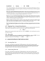
9.1
Wiring of the V1 RS422-PC Cable.......................................................................... 48
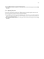
9.2
Wiring of the V1 RS422-Mac Cable ........................................................................ 49
9.3
Wiring of the standard RS422 Cable....................................................................... 50
9.4
Wiring of the RS422 Chase cable............................................................................ 51
9.5
GPIO Connector Pinout.......................................................................................... 52
9.6
MIDI and Biphase Connector Pinout: .................................................................... 52
10
DISK RECORD TIME / COMPRESSION CHARTS................................................ 53
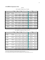
10.1 DCT Compression Chart......................................................................................... 53
10.2 MPEG2 Compression Chart ................................................................................... 55
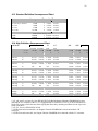
10.3 Standard Definition Uncompressed Chart.............................................................. 55
10.4 High Definition Uncompressed Chart..................................................................... 56
11
USING THE RCV2-9P REMOTE CONTROL.......................................................... 57
12
APPLICATION AND TROUBLESHOOTING INFORMATION .............................. 58
12.1 Unable to control V1 remotely ................................................................................ 58
12.2 Quick toggle between SHUTTLE & JOG modes..................................................... 58
12.3
Recording in case of tape drop-out ............................................................................. 58
12.4
V1 identification for DAW on the RS422 port .............................................................. 58
12.5 The unit is not playing smoothly in reverse play..................................................... 58
12.6 The Video has no colors .......................................................................................... 59
12.7 No Audio from input monitor .................................................................................. 59
12.8 Unable to write to active drive................................................................................ 59
12.9 Forcing power ON in any condition ....................................................................... 59
13
CONNECTING V1 TO AUDIO WORKSTATIONS & EDIT CONTROLLERS ..... 60
13.1 Connection to the DAWN workstation (v 4.3c or later) .......................................... 60
13.2 Connection to the Akai DD-1500 with RS422 control (recommended) .................. 60
13.3 Connection to the Akai DD-1500 in CHASE RS422 Mode..................................... 60
13.4 Connection to the Fairlight ..................................................................................... 61
13.5 Connection to the Microlynx, the Lynx 1 and Lynx 2 synchronizers ...................... 61
13.6 Connection to the Sonic Solutions........................................................................... 61
13.7 Connection to the Pro-Tools 4.0 ............................................................................. 61
13.8 Connection to the Orban AUDICY VX.................................................................... 62
13.9 Connection to the Dyaxis II..................................................................................... 62
13.10
Most Common Connection .................................................................................. 62
13.11
List of DAWs & Editors currently supported by the V1(*) ................................... 63
13.12
Using the V1 with Edit Controllers..................................................................... 63
14
INSTALLING SCSI DRIVES..................................................................................... 65
14.1 V1 and removable SCSI drives................................................................................ 65
14.2 Important Note about using Jaz Drives................................................................... 65
14.3 Mounting Data-Express on all DCT products except V1x2.................................... 66
14.4 Mounting Data-Express on the V1x2 without drive sharing................................... 67
14.5 Mounting Data-Express on the V1x2 sharing a drive............................................. 67
14.6 Mounting Data-Express on the V1-U...................................................................... 67
14.7 Mounting Data-Express on the V1-MP2................................................................. 67
15
ADDENDUM ................................................................................................................. 68
4
Warranty
Doremi's warranty obligations are limited to the terms set forth below:
Doremi Labs, Inc. ("Doremi") warrants this hardware product against defects in materials and workmanship for a period of ONE (1)
YEAR from the date of original retail purchase.
If you discover a defect, Doremi will, at its option, repair, replace, or refund the purchase price of this product at no charge to you,
provided you return it during the warranty period, with transportation charges prepaid, to the authorized Doremi distributor from
whom you purchased it or to any other authorized Doremi distributor within the country of original retail purchase. (You can obtain
additional information by contacting Doremi at the address printed on this certificate). To each product returned for warranty
service, please attach your name, address, telephone number, and a copy of the bill of sale bearing the appropriate Doremi serial
numbers as proof of date of the original retail purchase.
If your product fails during the warranty period while you are out of the country of original retail purchase, you may have it repaired
(no refunds or replacements are provided) at your expense by an authorized Doremi distributor in the country in which the product
failed. You may obtain a refund for the repair costs by submitting a claim to Doremi (instructions are obtained by contacting Doremi
at the address printed on this certificate).
This warranty applies only to hardware products manufactured by or for Doremi that can be identified by the "Doremi" and “V1”
trademark, trade name, or logo affixed on them. Doremi software is warranted pursuant to a separate written statement packed with
the software. Doremi does not warrant any products that are not Doremi products. This warranty does not apply if the product has
been damaged by accident, abuse, misuse, or misapplication; if the product has been modified without the written permission of
Doremi; or if any Doremi serial number has been removed or defaced.
THE WARRANTY AND REMEDIES SET FORTH ABOVE ARE EXCLUSIVE AND IN LIEU OF ALL OTHERS, WHETHER ORAL
OR WRITTEN, EXPRESS OR IMPLIED. DOREMI SPECIFICALLY DISCLAIMS ANY AND ALL IMPLIED WARRANTIES,
INCLUDING, WITHOUT LIMITATION, WARRANTIES OF MERCHANTABILITY AND FITNESS FOR A PARTICULAR PURPOSE.
No Doremi distributor, agent, or employee is authorized to make any modification, extension, or addition to this warranty.
DOREMI IS NOT RESPONSIBLE FOR SPECIAL, INCIDENTAL, OR CONSEQUENTIAL DAMAGES RESULTING FROM ANY
BREACH OF WARRANTY, OR UNDER ANY OTHER LEGAL THEORY, INCLUDING BUT NOT LIMITED TO LOST PROFITS,
DOWNTIME, GOODWILL, DAMAGE TO OR REPLACEMENT OF EQUIPMENT AND PROPERTY, AND ANY COSTS OF
RECOVERING, REPROGRAMMING, OR REPRODUCING ANY PROGRAM OR DATA STORED IN OR USED WITH DOREMI
PRODUCTS.
5
WARNING
THIS APPARATUS MUST BE EARTHED
IMPORTANT
WARNING
Power requirements for electrical equipment vary from area to area. Please ensure that your V1 meets the
power requirements in your area. If in doubt, consult a qualified electrician or Doremi Labs, Inc. dealer.
120VAC
220-230/240VAC
240VAC
@60Hz for USA and CANADA rating 1A
@50Hz for Europe rating 0.5A
@50Hz for Australia rating 0.5A
AVIS
Le voltage peut differer d’un pays a l’autre. Il faut que le V1 soit ajuste au voltage du pays.
LA SOURCE DE PUISSANCE DOIT AVOIR UN CONDUCTEUR CONNECTE A LA TERRE.
Toutes reparations doient etre effectuees par une personne qualifiee.
AFIN D’EVITER UN CHOC ELECTRIQUE, VEUILLEZ NE PAS ENLEVER LE CAPOT.
PROTECTING YOURSELF AND THE V1
Never touch the AC plug with wet hands
Always disconnect the V1 from the power supply by pulling on the plug, not the cord.
Allow only a Doremi Labs, Inc. dealer or qualified professional engineer to repair or reassemble the V1.
Apart from voiding the warranty, unauthorized engineers might touch live internal parts and receive a
serious electric shock
Do not put, or allow anyone to put any object, especially metal objects into the V1
Use only an AC power supply. Never use a DC power supply.
If water or any other liquid is spilled into or onto the V1, disconnect the power, and call your dealer.
Make sure the unit is well ventilated, and away from direct sunlight.
To avoid damage to internal circuitry, as well as the external finish, keep the V1 away from sources of
direct heat (stoves, radiators, etc.).
Avoid using aerosol insecticides, etc. near the V1. They may damage the surface, and may ignite.
Do not use denatured alcohol, thinner or similar chemicals to clean the V1. They will damage the finish.
Modification of this equipment is dangerous, and can result in the functions of the V1 being impaired.
Never attempt to modify the equipment in any way.
In order to ensure optimum performance of your V1, select the setup location carefully, and make sure
the equipment is used properly. Avoid setting up the V1 in the following locations:
1. In a humid or dusty environment
2. In a room with poor ventilation
3. On a surface which is not horizontal
4. Inside a vehicle such as a car, where it will be subject to vibration
5. In an extremely hot or cold environment
6
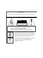
WARNING!!
To prevent fire or shock hazard, do not expose this appliance to rain or moisture
CAUTION
RISK OF ELECTRIC SHOCK
DO NOT OPEN
CAUTION:
!
TO REDUCE THE RISK OF ELECTRIC SHOCK,
DO NOT REMOVE COVER (OR BACK).
NO USER-SERVICEABLE PARTS INSIDE.
REFER SERVICING TO QUALIFIED SERVICE PERSONNEL.
The lightning flash with the arrowhead symbol superimposed
across a graphical representation of a person, within an equilateral
triangle, is intended to alert the user to the presence of uninsulated
“dangerous voltage” within the product’s enclosure; that may be
of sufficient magnitude to constitute a risk of electric shock.
!
The exclamation point within an equilateral triangle is intended to
alert the user to the presence of important operating and
maintenance (servicing) instructions in the literature
accompanying the appliance.
7
CE NOTICE
indicates compliance of the device to the EMC (Electromagnetic
Marking by the symbol
Compatibility) directive and to the Low Voltage directive of the European Community. Such marking is
indicative that this device meets or exceeds the following technical standard:
•
EN 55022 "Limits and Methods of Measurement of Radio Interface Characteristics of Information
Technology Equipment."
A "Declaration of Conformity" in accordance with the above standard has been made and is on file at
Doremi Labs, Europe, Valbonne, France.
8
INTRODUCTION
Thank you for your V1 purchase. The V1 is a random access digital video disk recorder that uses
magnetic drives (hard drives) as a recording medium.
To record video on a hard drive it should be digitized which means that the analog video
information must be converted to a digital data stream. Every NTSC video frame contains 525
lines that have 858 pixels each, however, only 480 lines with 720 pixels each are used to hold
picture information.
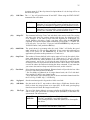
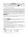
The table below indicates the bit rate standard definition (SD) and high definition (HD) video
without the use of compression.
Resolution
SD
SD
720x480 (NTSC)
720x576 (PAL)
8 bit encoding
Mbits/sec
166
166
HD
HD
HD
HD
HD
HD
HD
HD
1920x1080x60Hz
1920x1080x59.94Hz
1920x1080x50Hz
1920x1080x30P
1920x1080x25P
1920x1080x24P
1280x720x60P
1280x720x50P*
995
994
829
995
829
796
934
778
8 bit encoding
MBytes/sec
20.7
20.7
10 bit encoding
Mbits/sec
207
207
10 bit encoding
MBytes/sec
25.89
25.89
124.4
124.3
103.7
124.4
103.7
99.5
116.7
97.3
1244
1243
1037
1244
1037
995
1167
973
155.5
155.4
129.6
155.5
129.6
124.4
145.9
121.6
*Not implemented.
The V1 line of products includes uncompressed video recorders (8 and 10 bit encoding) and
compressed video recorders (8 bit encoding), the trade off is between storage requirement and
video quality.
V1 Uncompressed
The V1-U series records the video directly on the hard drive without the use of compression.
(V1-U & V1-Ux2 for standard definition video and the V1-UHD for HDTV video).
V1 Compressed ( DCT vs MPEG2 )
Doremi’s V1 product line includes models that use DCT compression (the V1, V1m, V1d, and
V1x2) and MPEG2 compression (V1-MP2).
DCT (Discrete Cosine Transform) consists of compressing every field of video and saving the
data on the drive. MPEG2 is a more advanced compression technique that yields a better transfer
rate than DCT for the same video quality. MPEG2 will yield better quality when recording on
DVD-RAM drives and larger servers can be built with MPEG2 units.
The CBS algorithm
The V1 uses a constant block size (CBS) algorithm. With traditional compression algorithms,
depending on video complexity, the size of each compression field can vary thus requiring
maintaining a list to indicate the start of each field on the drive. With CBS all fields have the
same maximum size. Consequently, CBS does not require maintaining a list indicating the start
of each field because they are all the same size. This results in a more reliable disk recorder with
faster video access and frame accurate recording.
9
Audio and Time Code
In addition to the video, and regardless of the compression ratio used, the V1 records 0, 2, 4, 6 or
8 tracks of uncompressed audio (sampled at 48Khz). Each audio sample is coded on 2 bytes
(2*2*48000= 192 KB/s) and every field of time code is sampled on 80 bytes (29.97*2*80= 4.795
KB/s for 2 channels in NTSC and 25*2*6= 4 KB/s for 2 channels in PAL). The V1 can also
record up to 8 channels of AES/EBU digital audio, up to 6 channels of analog audio, and 8
channels of embedded audio on SDI.
Hopefully this introduction has explained to the reader the basic technical principles of digital
video disk recording.
10
DESIGN OF MANUAL
This user’s manual covers the V1 MPEG2, DCT and Uncompressed series. Although the basic operation
of all V1 products is the same, there are minor differences. When a feature refers to only one product
series that function will be highlighted in bold with the name of the product as seen in the example
below:
>>DCT ONLY
>>MPEG2 ONLY
>>UncompSD ONLY
>>UncompHDTV ONLY
– for the DCT product series, V1, V1m, V1d, V1x2
– for the MP2 product series. V1-MP2
– for the Uncompressed standard definition video product series. V1-U
– for the HDTV Uncompressed product series. V1-UHD
Bold text is used when referring to buttons on the front panel of the machine or when referring to the
display of the LCD screen.
Clip & Segment: Note that throughout the manual the terms clip and segment are used interchangeably.
This manual was written with the latest product firmware numbers below.
DCT (V1, V1m, V1d, V1x2)
MPEG2 (V1-MP2):
Uncompressed (V1-U):
HDTV Uncompressed (V1-UHD):
4.16v
4.16v
4.16v
4.16v
Front Panel (RCV2) firmware
1.12
The V1 firmware can be checked by going to the Option Menu (hold the option button then press the
menu button). Scroll to Version No by pressing the down arrow key when you reach Option Menu 00.
Check the front panel firmware in the Controller Menu. Hold the ESCAPE button and press MENU.
And then scroll to Firmware.
If you have a newer 4.16 firmware than shown above, check the addendum pages on the back of this
manual for a list of changes and additions. If you have recently upgraded your firmware please print out
the README document included in the zip file with the new firmware. You can also download the latest
V1 manual from our tech support page “manual” section on the Doremi website
If you have an older firmware than shown above, then please upgrade your V1 to the latest firmware by
downloading the new firmware from our tech support page’s “firmware” section on the Doremi website.
If you will not be upgrading then please download the manual with the same firmware version as your V1
from the Doremi ftp page.
11
1 Setup Guide
1.1
Quick Start Guide for V1 DCT and MPEG2 machines
For more information about the items in bold, refer to Chapter 4 there you will find every Menu and
Option Menu command listed and explained. Note V1-U and V1-UHD drives are pre-installed at the
factory. See section 1.4 for setup information.
This quick start guide assumes the most common hardware setup: Single video channel V1 equipped with
a removable hard drive using the Kingston Data Express drive carrier and receiver. If you purchased your
Kingston and SCSI drive from Doremi, your V1 has been setup at the factory.
1. Plug the hard drive carrier in the Data Express receiver and turn the key counter clockwise until it
locks
2. Power the unit ON by pressing the Power On Switch. If you keep watching the LCD display on the
RCV2 or VToolsPro, you will see a “Scanning” message displayed for about 30 to 60 seconds (the
time it takes for the hard drive to be mounted)
i. The “Scanning” message should now disappear and you should get one of the
following:
1. A message saying “No MD Present” alternating with “Scanning”. This
means that this is the first time this drive is mounted on a V1 unit. If you
want to start using the drive:
a- Go to Option Menu 30 and select SINGLE FILE.
b- Set DISK-1 ID to the SCSI ID of the drive installed.
c- Set STRIPE ON to 1.
d- Set #RAIDSET to 1.
e- Go to MENU 7 and Initialize. In about 1 minute, the “Initialize”
message should disappear and you can start using the unit.
2. No message other than the Time Code and the Stop. This means that the
drive is recognized as a V1 drive and is ready to be used. Go to step 3.
ii. If you keep watching the LCD display on the front panel or VToolsPro and you don’t
see the any messages alternating, press the Menu button. If the menu disappears and
you don’t get a response, the V1 itself has a problem starting up. Refer to the
troubleshooting section.
3. Plug a valid video source on the composite input of the V1.
4. Plug a working monitor on the composite out of the V1
5. Go to the Sync Source menu and select your sync source. Ensure the selected sync source is present.
6. Go to the Menu and make sure Input Source is set to Composite
7. Go to Option Menu 3 (Set Video), press the ++ Key until you reach the Pattern Sub-menu, then
press the TOGGLE key to set the Pattern ON. This should display a pattern on your monitor. Press
the TOGGLE key again to set the Pattern OFF, then hit Escape.
8. If you have something recorded on the disk, it will be displayed on the monitor and hitting the Rec
button should set the unit in EE mode.
9. If you see a valid video signal on your monitor, you can press Rec and Play at the same time to start
recording on the V1
10. Hit Stop to finish the recording
12
1.2
Instructions for Initial Setup and Transport
♦
Before powering-up the V1 unit, please connect the SCSI termination supplied on the rear
external SCSI connector (If not there, the V1 will not operate properly). If you don’t see a SCSI
connector on the back of the unit, it means that the terminator is mounted internally.
♦
After powering-up, if your V1 has been ordered with a drive from Doremi Labs, you will be able to
play the initial "video test" recording (In NTSC for USA, PAL for Europe) without the need of an
external sync reference (Internal Sync. selected). If you need to play locked to House Sync, connect
a Black Burst signal to the SYNC IN connector and go to menu (02) Sync from, select the option
Sync In and validate by pressing ESCAPE.
♦
Before any transport :
1.3
♦
Lock the Data-Express (Key ON as for normal use).
Note: Doremi highly recommends shipping drives separately
♦
Switch the V1 OFF.
♦
Remove the SCSI termination on rear (Leaving it may break the SCSI connector during transport).
Setup of one or more drives on V1 DCT and MPEG2
♦ If you would like to combine the recording time of two drives, make sure the two drives are on
consecutive SCSI ID numbers i.e., 3 and 4. If not, then do not assign consecutive IDs. (Do not use
the factory set SCSI ID 7 set for the V1)
♦ Power up the first drive on ID4 (Turn on the key of the Data Express)
♦ Set the compression ratio to the desired value.
♦ Initialize the drive.
♦ Power up the second drive on ID3 and wait for about 1 minute.
♦ Go to Option Menu 30 and set the “First Disk” parameter to 3.
♦ Initialize the drive.
♦ Use Menu 4 to issue a mount command. The time left in Menu 10 should reflect the total time from
both drives
♦ Record. The V1 will start recording on the drive with the higher SCSI ID number and will continue
on the lower ID number. The jump from drive to drive is seamless.
This procedure can also be used to record on more than two drives with consecutive SCSI ID
numbers. As described above, each drive must first be initialized alone using the same bit rate
(compression ratio) for all drives, then all drives should be powered-up and initialized together. Use the
Mount menu command to mount all drives, if needed, before initializing them.
13
1.4
Setup of drives on the V1-U and V1-UHD
♦ Make sure the drives are on consecutive SCSI ID numbers i.e., 1 and 2 ( and 3 if you have 3 drives).
♦ Power up all drives (Turn on the key of the Data Express)
♦ Go to Option Menu 30 and set it to: “Multi File”, “First Disk” to 1, “Stripe Size” to 2 (or 3), “#RAID
Sets” to 1
♦ Initialize.
♦ The time left in Menu 10 should reflect the total time from all drives
♦ Record. The V1 will record across all drives at the same time.
For units connected to external storage, more than 3 drives can be used.
1.5
Single File System (SFS) Versus Multi-File System (MFS)
The single file system (SFS) is the original file system Doremi has been using in the V1 since the first V1
was introduced in 1996. It is based on opening 1 file for the whole disk and recording on it like a tape
machine. The SFS also allows multiple hard drives to be added in series for higher storage capacities.
The unit would start on the disk with the highest ID number and when full will continue on the lower
SCSI ID number. The SFS creates a header on the disk that has all information about the machine setup
and the clip definitions, so if the unit is turned off, clip definitions will be saved on the disk.
The multi file system (MFS) is the new generation file system that will allow multiple files creation on
the disk. The user will be able to load a file by its filename. The user can still generate clips within a file,
but the clip definitions will not be saved to disk and will be lost upon rebooting. The MFS allows for
RAID-0 striping across multiple drives and allows for controllers and automation systems that are Louth
or Odetics capable to control the V1 in a broadcast environment. On the MFS all file names are saved
and can be accessed after rebooting the unit by loading them using file names.
With firmware 4.16 and with the use of fast drives like the ST318452 and the ST336752, the V1-U can
be initialized in SFS to benefit from our clip saving capabilities for presentation applications. If the V1-U
is not equipped with these drives or other newer drives that are certified by Doremi, only the MFS should
be used.
14
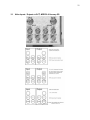
2 Front Panel Description
The V1 front panel contains space for two (3 1/2") half-height SCSI drives or 3 (3 1/2") Low Profile
SCSI drives, keypad, menu controls, transport controls, LCD display and an optional LCD video
confidence monitor.
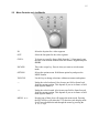
2.1
Keypad Area
1, 2, 3, 4 (Channel Selection): If your V1 has more than one channel use these buttons to
switch between the different channels. For single channel V1
machines channel "1" should always be selected.
AUD. SEL:
Audio Select button: Switches between audio channel pairs for
the headphone connection.
ALPHA-NUMERIC KEYPAD: This keypad is used to enter numeric data such as time
code addresses, in and out points, locate points, etc. To enter data,
simply begin typing the numbers and the display will automatically
overwrite. To abort an operation, press the ESCAPE key. The
display will revert to its previous setting. The BKSP (Backspace)
key can be used to correct typing errors. The keypad can also be
used to name video clips (segments) by using the corresponding
letters. (This Feature is not yet available)
RECALL:
Recall a saved video clip.
SAVE:
Save a video clip into a memory location number or name.
CLEAR:
Clears the display to enter new data.
ENTER:
Press after selecting a clip to play. Also used in the copy command.
15
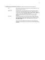
2.2
Menu Controls and Jog/Shuttle
IN:
Select the In point for a video segment.
OUT:
Select the Out point for the video segment.
GOTO:
To locate to a specific frame (field) from the V1 front panel, enter
the time code location numbers from the numeric keypad and press
GOTO.
ESCAPE:
This is the escape key. Press it when you want to exit the menu
mode.
OPTION:
Selects the options menu. Hold down option key and press the
MENU button.
TOGGLE:
Use this key to change selections within most menus and options.
--:
Nudge the value backward. Also locates one field or frame back
from the current position. This depends if you are in frame or field
mode (Option Menu 6).
++:
Nudge the value forward. Also locates one field or frame forward
from the current position. This depends if you are in frame or field
mode (Option Menu 6).
MENU !":
Pressing one of these keys will engage the menu mode. Pressing
the ESCAPE key will return the V1 to the time code display mode.
Scroll forward and backward through the menu by pressing the
! or " keys
16
JOG/SHUTTLE WHEEL FUNCTIONS: Activates the following function when lit:
JOG:
In Jog mode, the rotation of the Internal wheel will generate "Jog"
steps in forward or reverse.
SHUTTLE:
In Shuttle mode, the angle of the external wheel from its initial
position will control the shuttle speed with 7 different values in
each direction: 10%, 20%, 48%, 100%, 200%, 500%, 1000% in
>> or <<. The value used and the direction (">>", "<<") is
displayed on the bottom line of the LCD during the shuttle
operation.
Activates the external wheel for slow motion control. The slow
motion is forward only with predefined values of 0%, 3%, 10%,
15%, 20%, 26%, 30%, 39%, 48%, 60%, 65%, 75%, 81%,
87%, 93%, 100%
SLO MO:
The V1 uses a line shifting inter-field processing technique for
smoother motion during slow motion mode on standard definition
machines.
17
2.3
Transport Controls
The V1 standard transport controls are:
2.4
REC
Record control button. This key is used in several ways described later
in this menu.
STOP
Stop control button. The STOP key will cause the V1 to stop any
transport control (Play, record, rewind, fast forward).
PLAY
Play control button. If the active drive has recorded material, pressing
the PLAY key will start playback from the current location at normal
speed and the green LED will go ON.
REW
Rewind control button with a speed of 40 times normal. When the
rewind is close to the beginning of the recording, the speed is slowed
down to normal until it reaches the start. Pressing this key again will
increase the speed. There are three levels REW+REW+REW.
FF
Fast forward control button with a speed of 40 times normal. When the
fast forward is close to the end of the recording, the speed is slowed
down to normal until it reaches the end. Pressing this key again will
increase the speed. There are three levels FF+FF+FF.
LCD Time Code Display
The first line of the Time Code display shows the time location of the video material using the following
format: “HH:MM:SS:FF F1/F2” where "HH" represent the hours from 00 to 23, "MM" represent the
minutes from 00 to 59, "SS" represents the seconds from 00 to 59, "FF" represents the frames from 00 to
24 in PAL and 00 to 29 in NTSC, "F1/F2" represent the field: "F1" for odd fields and "F2" for even
fields. This display will show either Absolute Time or Time Code depending upon what the user has
selected in the "Time Mode" (01) Menu. The display also shows Drop/NonDrop information; “.” Means
NonDrop and “;”means DROP frame. Field one shows “.” Field two shows “:” or “;”
The second line displays the following:
♦ At the V1 start-up, the bottom left displays the version of the front panel (RCV2) software installed
on the flash EPROM (example, V .71 when version .71 is installed), then No Disk and Scanning
messages will alternate on the left side and Stop is displayed on the right side until a valid drive is
recognized on the SCSI bus of the V1, in such case No Disk will disappear and only Stop will be
displayed indicating that the V1 is now ready to access the drive. If No Disk/Scanning is still
displayed even though a disk was installed, the V1 did not recognize the disk. Check for SCSI ID
conflict or check the MD settings in Option Menu 30.
18
♦ During transport controls, the current operation is shown on the right side of the display: PLAY,
STOP, REWIND, FORWARD, RECORD, JOG, SHUTTLE, VAR..
("VAR" is indicated during play in chase on LTC/MTC or in variable speed from RS422)
♦ During shuttle movement, the shuttle speed is shown as :
If forward shuttle : ">> xx %" with xx % = 10%, 20%, 48%, 100%, 200%, 500%, 1000%
If reverse shuttle : "<< xx %" with xx % = 10%, 20%, 48%, 100%, 200%, 500%, 1000%
♦ During segment playback, the remaining time up to the OUT point is shown as "ssss : MM.SS",
where "sss" is the number of the segment played from 001 to 2047, "MM.SS" is the remaining time
up to the OUT point of the segment played in mn:sec
♦ During formatting, the message Formatting... is shown. During initialize, the message Initialize is
shown. During drive copy, the message Copying... is shown, once done, Copy Complete is shown
and if source drive has invalid recording, Bad Segment or Copy aborted is shown.
♦ During Stripe the message says initialize.
During the drives mounting (insert) and un-mounting (eject), the message No disk is displayed.
2.5
SCSI Drives
The V1 is shipped with a choice of standard SCSI storage devices: 3 1/2" half-height or low-profile (LP)
hard drives mounted internally inside the V1 or in a removable tray (Data-Express).
When mounted in a removable tray, hard drives can be removed (or installed) while the V1 is on-line
(without the need to shut the unit off). To remove (or install) a drive, insert the supplied drive key into
the key slot on the receiver below the lit SCSI ID number and turn it clockwise (or counter-clockwise).
When removing a drive, turning the key clockwise will unlock the drive and cut power off from it
causing it to spin down. Before removing a drive, wait until it has completely finished spinning
down. This will usually take about 30 to 40 seconds depending on the drive. The Data Express receiver
inside the V1 sets the SCSI ID. All V1 internal drives should not be terminated. The external SCSI
termination supplied with the V1 should be mounted before powering up. If there is no SCSI connector
on the back then the terminator has bean mounted internally.
Additional SCSI drives can be added to the V1 rear panel SCSI connector. All drives on the external
chain should not be terminated except for the last drive in the chain, which should be terminated. When
no drives are connected externally, connect the supplied SCSI terminator to the SCSI connector on the
back of the V1.
DO NOT USE THE SCSI ID ASSIGNED FOR THE V1 IN OPTION MENU 17 FOR ANY OF THE DRIVES
CONNECTED TO THE V1.
19
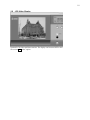
2.6
LCD Video Display
Optional LCD video confidence monitor. The display can be turned OFF or ON.
See section 4.3 “video” option.
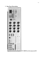
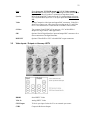
20
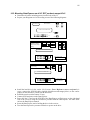
3 Rear Panel Description
DCT, MPEG2 and Uncompressed SD
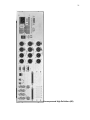
21
Uncompressed High Definition (HD)
22
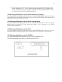
3.1
Video Inputs / Outputs >>DCT, MPEG2 & Uncomp SD
23
Note :
Sync In
3.2
Please do not use YUV/RGB output and Y/C (S-Video) outputs at
the same time because these signals are coming from the same buffered
outputs and so this will produce a mismatch on impedance loads.
House Sync input BNC connector for the V1 synchronization reference.
Use only Black Burst Sync here. Your Sync input should not exceed 1V
P-P.
Video
Analog Composite video input and output BNC connectors. Video IN is
where you connect your video signal for recording to the V1 and Video
OUT is for connection to a video monitor or another video recorder.
S-Video
Two separate Y and C BNCs. You must use a Y/C to Mini DIN-4
adaptor for single cable S-VHS applications.
SDI
Optional. Serial Digital Interface input and output BNC connectors for a
direct connection with digital betacams.
RGB/YUV
Optional. Three RGB or YUV selectable BNC output connectors
Video Inputs / Outputs >>Uncomp. HDTV
HDSDI
Serial HDTV Video
Y Pb Pr
Analog HDTV Video
SYNC Input
Tri-level sync input. Locks the V1 to an external sync source
CVBS
Composite Reference Output
24
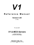
3.3
Audio Inputs / Outputs
Analog Audio:
2channel analog XLR inputs and outputs. These XLR connectors are the
balanced analog audio inputs and outputs. Pin 2 is hot (+), pin 3 is cold
(-), and pin 1 is ground.
Digital Audio:
4 channel digital XLR inputs and outputs. Transformer balanced
AES/EBU input and output. Pin 2 is hot (+), pin 3 is cold (-), and
pin 1 is ground.
Audio Expansion1: Expansion Card Slot holds one of the following
A- 4 Channels AES / EBU
B- 2 Channels analog audio
Audio Expansion2: Expansion Card Slot holds one of the following
A- 4 Channels AES / EBU
B- 2 Channels analog audio
3.4
9 Pin Connectors
GPIO:
General Purpose inputs and outputs
RS-422-1:
Primary serial interface connector to the V1. Connector 1 should be
connected to your edit controller or workstation, while connector 2
is used to connect the optional RCV2 external remote control from
Doremi Labs, Inc.
RS-422-2/ Midi + Biphase: If all 9 jumpers on J34 are set to the RS422 position, this connector
will be used as a second RS422 port (this is the default setting when the
unit is shipped). If all 9 jumpers on J34 are set to MIDI+BP position, this
connector will be used as a MIDI I/O and Biphase input with a +5V
supply.
3.5
Ethernet Connector
Ethernet: RJ45 connector 100BaseT
3.6
Time Code
Balanced TRS 1/4" input and output connectors for LTC time code. The V1 time code input
accepts balanced signals (tip hot, ring cold & sleeve is ground). If you are feeding an unbalanced
signal to it, both ring and sleeve should be connected to GND. You can use an unbalanced jack
(tip and sleeve) on the time code input of the V1. The V1 time code output is a balanced signal
(tip hot, ring cold & sleeve is ground). If you are feeding it to an unbalanced input, ring should
not be connected to anything. You cannot use an unbalanced jack (tip and sleeve) on the time
code output of the V1. If you connect time code from one V1 to another the cable should be
balanced on both ends.
25
3.7
SCSI
Standard 68-pin female connector for connection to external SCSI drives. When no external
SCSI devices are used, make sure the supplied terminator is connected here. When connecting
external drives, the last drive in the chain should be terminated. All V1 internal drives supplied
by Doremi Labs, Inc. are non-terminated.
This connector may not appear on your unit because the terminator was placed inside the unit.
3.8 115V / 230V
Confirm that the proper voltage is selected for your area on the power supply. The switch is
located next to the power connector.
26
4 Menu & Option Selections
From the front panel, you have access to three different sets of menus. Pressing the MENU key will
provide access to the “Standard Menu” and pressing OPTION MENU (hold the OPTION key while
pressing MENU) will allow access to the “Options Menu”. Pressing the ESC and MENU key will
provide access to the “Controller Menu”. If you don’t have a front panel controller, you can either use
the VToolsPro utility or the RCV2 stand-alone controller.
4.1
Standard Menu
The MENU key will call up the menus allowing the user to define the set-up of the V1 unit. The up
arrow key ! (or down arrow key ") will allow the user to get to the next (or previous) menu selection.
The TOGGLE button generally sets the parameters for the selected menu. Press TOGGLE to increase
the parameter and hold OPTION and TOGGLE to decrease the parameter.
Once menus are set-up, pressing the ESC key will save the settings and quit the menu mode. All the
settings related to the recording i.e. Remote/Local, Time Mode, Sync Source, Input Source, etc. are
automatically saved on the current disk when you exit the menu mode
Menus (00), (01), (02), (04), (05), (06) and (10) are saved on the active drive. So if this drive is mounted
on another V1 unit, all these settings will be recovered.
(00)
Control
Selects the mode of control for the V1. The TOGGLE key will switch between:
Local
Remote
(01) Time Mode
For front panel control of the V1
For control of the V1 by an external edit controller or workstation
via the rear panel RS-422 connectors
Selects the Time Code source of the V1 during playback. Regardless of the setting
for this option, the V1 will record the time code present on the video input on the
VITC track, and the time code present on the LTC input on the time code track.
This menu option will allow you to choose the time code during playback. The
TOGGLE key will switch between:
Absolute Time, the time code displayed on the V1 front panel
and present on the TIME CODE OUT connector during
playback or record is generated internally by the V1. A Time
represents the time elapsed since the start of the recording unless
a time code offset has been set. See Section 5.1.4, “Time Code
Offset”.
Time
During record the time code present on the TIME CODE IN
Code
connector will be recorded on the time code track (guide track)
of the V1 active drive, a valid LTC signal should first be fed to
the V1 LTC IN connector. The time code displayed on the V1
front panel and present on the TIME CODE OUT connector
during playback or record is the same time code recorded on the
time code track, unless a time code offset has been set. See
Section 5.1.4 "Time Code Offset".
A Time as If you are using A Time (with or without an offset) as your time
code and if your controller requires time code, you should
LTC
choose this option, which will make the A Time look like Time
Code on the RS422 connection.
A Time
27
During record, the time code embedded in the video input signal
(VITC) will be recorded on the VITC track of the V1 active
drive. The time code displayed on the V1 front panel and present
on the VITC OUT connector during playback or record is the
same time code recorded on the VITC track, unless a time code
offset has been set. See Section 5.1.4, "Time Code Offset".
VITC
Time
(02)
Sync from
Specifies the sync reference during playback. The V1 is always locked to the
Input when recording. The TOGGLE key will switch between:
Auto
Sync In
Input
Input+VCO
Internal
(03)
Chase
Specifies how the V1 will chase to time code. The TOGGLE key will switch
between:
Off
LTC
MTC
Serial TC
(RS422)
Biphase
Note:
(04)
The V1 syncs to the SYNC IN input.
The V1 syncs to the SYNC IN input. Auto and Sync In are
the same.
The V1 syncs to the VIDEO IN input.
UncompHDTV ONLY
Sync to input using a VCXO for a low jitter playback.
The V1 syncs to its own internal clock.
Normal mode of operation when the unit is controlled by a
workstation via the 9 pin connection.
In this mode the V1 will chase the time code fed through the
TIME CODE INPUT jack. This mode is recommended when
no RS422 9 pin control is present (See Sections 5.2.1 and 5.2.2,
Chase Play.)
In this mode the V1 will chase the time code fed through the
MIDI IN connector. This mode is recommended when no RS422
9 pin control is present. This feature may no longer be supported
by Doremi Labs.
In this mode the V1 will chase the time code received on the
RS422 connection. This mode requires a special cable and it is
recommended only if no RS422 9 pin control is present. Please
refer to Paragraph 9.4, "Wiring of the RS422 Chase Cable" for
more information on how to build the cable.
In this mode the V1 will chase the Biphase input clock signal.
Option Menu (18) "Clks/Frame" should be setup properly in
order to select the clock frequency. Please refer to option menu
(18) at the end of Section 1.2. To use the Biphase mode, the
internal cable of the second RS422 port should be connected to
J3 on the main motherboard. Please refer to Section 5.2.4 for
information.
The Chase to LTC Mode above is different than the OPTION PLAY
Command also referred to as Chase Command (note the difference
between Mode and Command, See Sections 5.2.1 and 5.2.2 for an
explanation of the difference).
Mount
If you have more than one drive powered up, this command will mount the drive
with the highest SCSI ID number. Press the TOGGLE key. The message “Are you
sure?” will appear on the LCD screen,
♦ If you want to mount, hold the OPTION key and press the “--“ key again.
♦ If you change your mind and don't want to mount, press ESC.
(05) Input From
Specifies which video input of the V1 is active. The TOGGLE key will switch
between COMPOSITE, S-VIDEO, YUV, RGB OR SDI, depending on the
model and options you have installed.
28
(06)
Compress
(Bit Rate for MPEG2 units, Compression Ratio for DCT units and select between
8 and 10 bit for the V1-U) An initialize command should be executed in order for
the new setting to be valid for the new recording. Pressing the TOGGLE key on
the MPEG2 or DCT units will increase the ratio then it will recycle. Holding down
the OPTION key while pressing the TOGGLE key will decrease the ratio.
(07)
Initialize
This command wipes (deletes) all previous recordings, and writes all the new setup parameters selected in the menus on the active drive. A disk that was never
initialized on the V1 will display the message "No MD Present" until it gets
initialized. Use this command to change the compression ratio. To initialize a disk,
press the TOGGLE key.
A message will appear on the LCD screen: “Are you sure?”:
♦ If you want to initialize, hold the OPTION key and press the
TOGGLE key again, the LCD will display "Initialize.." and
initialize the disk. Once done, the message "Initialize.." will
disappear and the drive is now ready for recording.
♦ If you change your mind and don't want to initialize, press ESC.
CAUTION NOTE !!
OPTION MENU 30 should be set properly before initializing a drive.
(08)
Format
This command wipes all previous recording and prepares the active drive for
optimal V1 performance. Brand new drives do not need formatting. The Format
command should always be followed by an Initialize command. To format a disk,
press the TOGGLE key. You will be prompted with the following message: “Are
you sure?”:
♦ If you want to continue, hold the OPTION key and press the -- key
again, the LCD will display "Formatting..." and will format the disk.
Once done, "Formatting..." is cleared and the drive is now ready for
the Initialize operation.
CAUTION NOTE !!
Formatting a drive is a long procedure, please do not attempt to use the V1
until the format operation is complete and DO NOT SHUT OFF THE V1
DURING THE FORMAT OPERATION
(If the V1 is switched off during the format operation, you will need to restart the
format operation).
The format operation is a long procedure that depends on the size and speed of the
drive.
♦ If you change your mind and don't want to format, press ESC.
CAUTION NOTE !!
OPTION MENU 30 should be set properly before formatting a drive.
Once Format and Initialize have been executed on a drive, it is not necessary
to Format again. Initialize is enough for erasing the drive.
(09) Drop Frame
This option is only valid when Time Mode is set to A-Time or A-Time As LTC in
NTSC mode (See Section 5.2, "Special Playback Functions"). The TOGGLE key
will switch between Drop and Non Drop.
29
(10)
Time Left
This menu selection will display how much time (HH:MM:SS:FF) is still available
on the disk from the end of the existing recording. The total duration is calculated
using the disk capacity detected, the compression rate, and the number of audio
channels. After an Initialize command, Time Left displays the full capacity of
the drive in "HH:MM:SS:FF" format. If you call this menu during recording, it will
show the time left at the moment it was activated. When the drive is fully recorded,
"Time Left" will display 00:00:00:00 and you are only allowed to record over
existing material. When this menu selection is active pressing the ++ key will
update the time left.
30
4.2
Option Menu
Hold the OPTION and the MENU key to call up the “Option menus”. The up arrow key ! (or down
arrow key ") will allow the user to get to the next (or previous) menu selection. If there are submenu
selections for the Menu items use the ++ or – buttons to scroll through the selections. The TOGGLE
button generally sets the parameters for the selected menu. Press TOGGLE to increase the parameter
and hold OPTION and TOGGLE to decrease the parameter. Once menus are set-up, pressing the ESC
key will save the settings and quit the menu mode.
OPTION Menus (05) and (06) are saved on the active drive. So if this drive is mounted on another
V1 unit, all these settings will be recovered.
V1 Info.
If you are in Option Menu (00) and hit the down arrow key, the V1 will display
information about the unit. The TOGGLE button will switch between: Version
Number, IP address, Ethernet Port Address, the amount of RAM used on that unit
and the unit’s serial number.
(00) Auto Play
>>DCT & MPEG2 ONLY If you enter a segment number that is already defined
(See Section 5.2.5 "Segment Definition & Playback"). The V1 will play that
segment every time it mounts that drive. This function can also be used to
automatically locate to a start point every time the disk is mounted. All you need to
do is set the IN and OUT time at the same location for the auto-play segment.
(01) Disk Copy
>>DCT & MPEG2 & UncompSD (single file system) ONLY This feature will
allow you to make duplicates of one recording from one disk to another without
the need to re-record the video thus allowing video, audio time code, segments
definition and menu set-up to be transferred digitally from one drive to the other.
First make sure your source disk is the active drive (when you hit play, only the
source disk should be playing) then power up (insert cartridge in) your destination
drive(s). Engage the Disk Copy menu, the ++ key will switch between each of the
following sub-menus:
Source is
# Targets
Target #1
Segment #
Full Disk
Type the SCSI ID number of the source drive (Valid range from
0 to 15), then use "++" to go to the next sub-menu.
Type the number of drives that will act as your destination
drives (Valid range from 1 to 4), if you enter a value higher than
the maximum allowed, the V1 will default to its maximum, then
use "++" to go to the next sub-menu.
Type the SCSI ID number of the destination drive number 1
(See Caution below). If you specify more than one target, you
will be prompted for Target #2, etc..., then use "++" to go to the
next sub-menu.
If you wish to copy only a segment (already defined on the
source drive), enter the segment number, from 1 to 2047, and if
previous menus 1,2,3 have the values you need, press ENTER to
start the copy process. If you need to perform a full copy, then
use "++" to go to the next sub-menu.
If you wish to copy the full disk, and if previous menus 1,2,3
have now the values you need, press ENTER to start the copy
process. If you do not want to perform the copy operation at this
time hit ESC , use "++" or "--" to go to other sub-menus.
31
Important notes:
♦ Hitting ENTER after each of these sub-menus will save your choice
and launch the copy operation, so do not press ENTER until you
have entered all the correct values in the sub-menus.
♦ The destination drive must be previously initialized on a V1. The
copy will be aborted if the destination drive is not a V1 drive.
♦During the copy process, the LCD will display a counter showing
how much is left to be copied (in Gbytes, Mbytes), when finished, it
will display "Completed".
♦ The copy process will only copy valid recordings from the source
drive. If the source drive has invalid recordings or bad sectors in the
recording to be copied, the LCD will display "Copy aborted" and
will abort the copy process. In this case check your recording on the
source drive, and record it again if it is damaged or contains bad
sectors.
♦ Caution! : Your destination drive will be fully erased by the
copy.
(02) Edit Preset
This feature will allow you to select which audio track(s) to edit/overdub while
the other non selected track(s) are monitored at the same time. For the V1-U the
overdub feature is only supported on the Seagate Cheetah SCSI hard drives 15k
RPM. For the V1-MP2 & DCT you can use 10k RPM drives. For the V1-UHD it
requires at least 4 15000 RPM drives or the dual-SCSI external drive setup. In
addition the with the V1-UHD you can do “assemble” or “audio” only.
This feature is used only when you are using the front panel to do the overdub. If
you are using an edit controller the edit controller will set these options
automatically. The settings the edit controller has selected will be reflected here.
The ++ key will switch between the following selections:
A1
A2
A3 to A8
TC
Video
Assemble
Insert
To insert/overdub on audio track 1, select On by pushing the
TOGGLE key.
To insert/overdub on audio track 2, select On by pushing the
TOGGLE key.
If your V1 includes additional Audio in/out tracks (up to 8) they
will be listed consecutively here
To insert/overdub time code on the guide track, select On by
pushing TOGGLE key. Note that you can use the "Time Code
Offset" function and keep this option Off.
To insert/overdub video, select On by pushing the TOGGLE key.
If this submenu is set to On by pressing the TOGGLE key, all
previous submenus 1., 2.,3. & 4 will default to the On position and
the drive is set for normal recording (video, audio and time code).
You can select Off by pressing the "--" key. The reason for the
On/Off toggle for video is to allow the V1 to record while in
PLAY mode (Usually required by Editors using RS422 control), in
this case, the sub-menu Assemble must be On.
Select On or Off by pressing the TOGGLE key. Enables or
disables the ability to insert video or audio using the front panel.
The overdub procedure is explained further in Section 5.1.2
32
(03) Set Video
This menu option will allow you to set the video parameters. The ++ key will
switch between:
This parameter sets the delay until the video output goes black
(screen saver). Hold the OPTION and the TOGGLE to move
the delay down by 10 seconds, TOGGLE will move it up by 10
seconds. "000" will disable this feature, "010" will cause the
unit to output black video when the unit is idle for 10 seconds.
Video Pattern. Use the TOGGLE button to switch between ON
Pattern
and OFF.
Use the TOGGLE button to select the output as RGB, YUV or S
Out
Video
Chroma Phase. Use the TOGGLE button to increase or decrease
CH PH
the chroma phase from 0 to 360. You can also enter a number
from the keypad followed by the ENTER key
HTRIG
HTRIG adjustment. Use the TOGGLE key to set the HTRIG
on/off
adjustment ON or OFF.
HTRIG
Hold the OPTION and TOGGLE key to move the picture to
value
the left, TOGGLE will move it to the right. You can also enter
a number from the keyboard followed by the ENTER key.
Sets the black level to 0V for the Japanese standards and 0.75V
Black
for the American standards. Used in NTSC only.
PAL Switch 0 or 1. Use the TOGGLE button to set the value according to the
PAL standard used in your area (A or B)
Luma Brightness. Use the TOGGLE button to set. 00 is the
Luma Brit
default value of the analog input.
Luma Contrast. Use the TOGGLE button to set. 00 is the default
Luma Cont
value of the analog input.
Chroma Sat Chroma Saturation. Use the TOGGLE button to set. 00 is the
default value of the analog input.
Chroma Hue. Use the TOGGLE button to set. 00 is the default
Chroma
value of the analog input.
Hue
Composite Brightness. Use the TOGGLE button to set. 00 is the
Comp Brit
default value of the analog input; Component YUV/RGB
Composite Contrast. Use the TOGGLE button to set. 00 is the
Comp Cont
default value of the analog input; Component YUV/RGB
Composite Saturation. Use the TOGGLE button to set. 00 is the
Comp Sat
default value of the analog input; Component YUV/RGB
Use the "++" or "--" to set the VTRIG Adjustment. 00 is the
VTrig
default value. The "--" will move up the picture, "++" will move
it down. You can also enter a number from the keyboard
followed by the ENTER key.
This option is not saved on the drive, it is saved on the V1 flash EPROM only if
you execute a Save from optional menu (04).
Delay
(04)
Save
This menu option will save all the Flash EPROM settings of the V1. To write the
changes on the Flash EPROM (see Note below), press the ++ key.
A message will appear on the LCD screen: “Are you sure?” :
♦ If you want to save, hold the OPTION key and press the “--“ key again,
The V1 will write the changes on the Flash EPROM.
♦ If you change your mind and don't want to save, press ESC.
NOTE: THIS FUNCTION SHOULD NOT BE ABUSED BECAUSE THE
FLASH EPROM CAN ONLY BE WRITTEN 2000 TIMES. IF YOU SAVE
YOUR SETTINGS ON THE FLASH EPROM MORE THAN 2000 TIMES
YOU MIGHT DAMAGE IT AND NEED TO REPLACE IT BY SENDING
THE UNIT BACK TO DOREMI LABS.
33
(05)
Disk Access
This menu option will allow you to write protect your drive. The TOGGLE key
will switch between Play Only and Play & Record (Default). When Play Only is
selected, you will not be able to record on the disk or initialize it. This option is
saved on the disk. Setting is saved on the active drive. So if the drive is mounted
on another V1 unit, these settings will be recovered.
(06) Frame Mode Select the TOGGLE button to switch between Frame Mode ON, OFF and Play
Only. When ON the V1 will stop on a frame and in slow motion it will play frame
by frame. When OFF the V1 will stop on a field and in slow motion it will play
field by field. In Play Only, the V1 will stop on a field and in slow motion it will
play frame by frame. This setting also affects the Step Recording option. For Slow
Motion application, the frame mode must be OFF. When the V1 is in stop (freeze)
mode and Frame Mode is set to ON a full video frame will be displayed. Setting is
saved on the active drive. So if the drive is mounted on another V1 unit, these
settings will be recovered.
(07)
(08)
(09)
Step Rec
Step Recording. Select the TOGGLE button to switch between Step Recording
enabled or disabled. When enabled, every time the V1 goes into record, it will only
record one frame (or field depending on the Frame mode setup). This option is
useful for animation. When Step Recording is disabled, the V1 is in normal mode
of operation. If you want to record video only without altering the previously
recorded audio, press the ++ key. This will give you the option of recording “All”
or “Video Only”. You can switch between the two modes using the “++” key. Step
record cannot be enabled on the MPEG2 products.
Clip Menu The TOGGLE key will go to the beginning of the next or previous clip (segment).
This menu only shows previously defined segments. For more information on
defining segments see Section 5.2.5 "Segment Definition and Playback"). You can
also type the clip number using the keypad followed by the ENTER key, if you
enter an undefined clip number the V1 will locate to the previous clip (segment).
When a clip other than 0 is selected here, the V1 operations will be restricted
between the boundaries of that clip.
Vid Optns
The video options menu features settings for VITC (vertical interval time code),
close captioning and the time code burn-in window.
VITC In
VITC Out
CC Out
BIW Pos
Select off or the line number the source VITC is on (10 to 18)
(Recommended Values: NTSC:14 - PAL:19)
Select off or the line number to output VITC on (10 to 18)
(Recommended Values: NTSC:14 - PAL:19)
Close Caption. Set to on or off to allow close caption to pass
through the V1. (Analog and SDI Video)
Time Code Burn-in window. Position on the screen at Top-Left,
Top-Center, Top-Right, Bottom-Right, Bottom-Center, BottomLeft (Analog Video Outputs Only)
Select off, black on white, or white on black numerals.
BIW
Mode
This selection is saved on the machine after executing (04) Save.
(10)
Audio In
(11)
SCSI Speed
To ensure lossless audio on the digital input, it must be sampled at 48.000Khz and
phase locked to the video input. If you feed digital audio at a different frequency,
or if it is not phase locked to the video, the V1 will re-sample the audio at 48Khz
which might produce undesirable clicks.
Select the TOGGLE button to switch between analog, AES/EBU or embedded
audio on SDI, depending on the options installed.
Use to set the SCSI Parameters. The different submenus and selections are:
Clock: 10MHz, 20MHz or 40MHz
Width: 8bit or 16 bit
Termination: ON or OFF
34
For standalone units working with Wide SCSI drives, the settings should be:
40-16-ON.
For units installed with the V1Xserver, the settings should be: 10-16-ON.
For the MPEG2 and DCT units with a loop SCSI cable (2 SCSI connectors in the
back), the Termination should be OFF.
(12)
V1 Type
Select the TOGGLE button to switch between Player Only or Rec/Player. This
option is used when more than one V1 unit are connected to the same drive or
RAID. You can only have one unit set in Rec/Player and all the rest should be
Player. The Rec/Player is the only unit allowed to record on the network.
Important Note: When the unit is in Player Only mode, all operations that write
to the active drive are denied, including record, initialize, format, etc.
(13)
Video Type
Select the TOGGLE button to switch between NTSC and PAL. If you want the
new setting to be the default startup setting, a Save command should be executed
after changing this parameter. The unit will switch only after the drive is
initialized.
>>UncompHDTV ONLY This function allows you to select between the different
HD formats of your source below by pressing the TOGGLE button:
1080 50i
1080 30p
1080 25p
1080 60i
720 60p
1080 24p
Selects 1080 line interlaced 24 frame /sec standard
Selects 1080 line progressive 30 frame /sec standard
Selects 1080 line progressive 25 frame /sec standard
Selects 1080 line interlaced 30 frame /sec standard
Selects 720 line progressive 60 frame /sec standard
Selects 1080 line progressive 24 frame / sec standard
(17)
SCSI ID
Select the TOGGLE button to switch between 0, 1, 2, ..14 and 15. The selection
represents the SCSI ID number of the V1 after restart. Do not use a SCSI ID
number for the V1 that conflicts with any installed drive. A Save command
should be executed after changing this parameter. The default SCSI ID is 7.
(18)
Clks/Frame
Select the TOGGLE button to switch between 01, 02, 04, 10. The selection
represents the number of clicks on the incoming Biphase signal per video frame
(01= 1 click per frame). In PAL 25 frames/sec, 01=25Hz, 02=50Hz, 04=100Hz,
10=250Hz. If you want the new setting to be the default startup setting, a Save
command should be executed after changing this parameter.
(19)
Emulation The "++" or "--" will toggle between V1 (default), BVW-75 and DVW-500. If you
want the new setting to be the default startup setting, a Save command should be
executed after changing this parameter.
(20)
# Audio Ch
Select the TOGGLE button to switch between 0. 2. 4. and 8 which designate the
number of audio channels to be recorded. Changing this menu will take effect only
after you initialize the drive.
(21)
Jog On
Select the TOGGLE button to switch between “1&2”, “3&4”, “5&6” and “7&8”.
When the V1 is playing at any speed below 100%, the audio will output from only
two channels. Use this option to select which tracks the audio will be on when the
V1 is playing at any speed below 100%.
(22)
Loop Mode Select the TOGGLE button to switch between OFF and ON. When this option is
set ON, the V1 will record (play) in a loop specified by the clip (segment) selected
35
in option menu (8). If the clip selected in Option Menu 8 is 0, the loop will be on
the whole disk space.
(23)
Edit Time The “++” key will switch between IN and OUT. When using the EDIT ON/OFF
commands from a P2 editor
EDIT IN
EDIT OUT
2, 3, 4 or 5 frames. Pressing TOGGLE specifies the number of
frames the V1 will wait before it starts recording after receiving
an EDIT ON command. For MPEG2 units this should be set to 5.
2, 3, 4 or 5 frames. Pressing TOGGLE specifies the number of
frames the V1 will wait before it stops recording after receiving
an EDIT OFF command. For units this should be set to 5.
(24)
Stripe TC
This command will stripe Time Code with black video and no audio. The striping
will start at the time line position starting with the time line displayed on the
LCD. Example: If you want to stripe time code beginning at 01:00:00:00, you
would: Initialize your drive. Create a one hour offset using the OPTION IN
command. Then use this Option Menu command by pressing the “++” button. The
LCD will reply: "Are you sure". If you are, hold the OPTION Key and press the
TOGGLE button, if not just hit the ESC key.
(25)
Odd Fields
The speed shown in percentage after the word “Under” will define the speed
under which the V1 will only play odd fields. If you want to play odd and even
fields at all speed, use the TOGGLE key to select 0%. For Slow Motion
applications you must set this parameter to “0” and save it.
(26)
Stop Chase
The number of frames defined in this option menu will set the free-wheel of the
chase mode between 1 and 10 frames or “0”. When set to “0”, the V1 will play
the same field for the whole duration of the time code drop-out. When set to a
value between 1 and 10, the V1 will play the same field for the specified amount
of frame(s) before it stops and wait for the new time code to chase. This function
is useful to reduce the audio noise during the chase command. If you know that
your source does not have drop-outs in the time code, set this value to 1.
(27)
Fast Mode
Select between normal and enhanced. Enhanced mode will provide the best video
preview in Fast Forward and Fast Rewind
- Set Fast Mode to Enhanced on all single channel units, the V1x2 with dualdrives and the V1-MP2 in one channel mode.
- Set to Normal for units connected to the V1Xserver and multi-channel units like
the V1x2-1r2p, V1MP2-1r2p, V1-UHD-1r2p.
(28)
Jog Speed
Sets the maximum speed in Jog mode to 100% or no limit.
(29)
Still Mode
Sets the mode of the V1 stop mode to either show a field/frame from the drive
(Still) or show the image present on its input (EE). In EE mode, pressing Stop
more than once will show the image from the drive.
(30)
File Type
The use of this Option Menu is necessary to define the SCSI ID of the active disk
and to create a file system that uses multiple disks (RAIDSET) in the Multi File
system mode. The selections are:
Single File or
Multi File
See Section for definition of Single file and Multi-file systems.
>For DCT and MPEG-2 use Single File (SFS)
>For Uncompressed use Multi File (MFS) or see UncompSD
note below.
Disk-1
Sets the SCSI ID of the active disk (Single File) or SCSI ID of
the first disk in the RAIDSET (Multi File)
36
Stripe On
#RaidSets
Sets the number of disks in the RAIDSET. Use “1” for Single
File.
Sets the number of RAIDSET to be defined. This parameter
should be set to “1”.
UncompSD ONLY: If the V1-U is equipped with the fast ST318452 or
ST336752 drives, it can be initialized in Single File system, which does not allow
striping but allows daisy chaining and allows for the clips to be saved on the
drive. If the V1-U is not equipped with these drives or other newer drives that are
certified by Doremi, only MFS should be used.
UncompHDTV ONLY: The V1-UHD unit can use two SCSI bus in striping
mode to allow max possible performance as required when audio insert has to be
done while video is playback. For this unit the Menu entry is :
Multi File:
Bus :1 Use Single Bus
Bus :1 + 2 Use 2 Buses
Stripe On: Sets the TOTAL number of disks in the RAIDSET. minimum 3
using 15Krpm Cheetah.
#RaidSets: Sets the number of RAIDSET to be defined. This parameter
should be set to “1”.
Bus:1 Id: xx : Sets the first SCSI ID of bus 1 – all other IDs should be
consecutive to the first
Bus:2 Id: xx : Sets the first SCSI ID of bus 2 – all other IDs should be
consecutive to the first
If you try to initialize a unit and if the drives installed do not match the
parameters set in this option menu, you will get a message “Failed check MD”.
(31)
Port Setup
Defines the protocol used on the RS422 PORT1 and RS422 PORT2 located on
the back of the unit. Each port can be individually set to emulate:
P2 Protocol: Sony P2 protocol at 38400 bauds
LD Protocol: Pioneer Laser Disk Protocol at 4800 or 9600 bauds.
(32)
Audio lvl
Sets the audio input level for each analog audio channel separately. Press
TOGGLE to increase the level, press OPTION and TOGGLE to decrease the
level.
(33)
GPIO Port
Is used to enable or disable the GPIO for units that have the GPIO option board
installed. If the Option board is not installed, this option menu should be disabled.
A future software release will allow the user to specify the functions of the 3 GPIs
and GPOs. In the current software the 3 GPIs are set to:
GPI 1: Play previous available segment (= Pin 1 to set at GND level),
GPI 2: Reset segment number to 0 (= Pin 7 to set at GND level),
GPI 3: Play next available segment (= Pin 3 to set at GND level).
GND
1
GPI3
3
GPO3
2
GND
4
GPI1
5
GPIO connector on Back Panel
GND
6
GPO2
7
GPI2
8
GPO1
9
GPI inputs are TTL ACTIVE LOW signals to be controlled by closing
contacts: Contact closed (Between GPI & GND) = Level 0 on that GPI =
Command as listed
(Open GPI has a voltage of TTL high level so between 3.5 & 5V)
37
The V1 will also send a trigger to output pin 1, pin 2 or pin 3 after it
completes the playback of a segment. The pin number is determined by the
remainder value when dividing the segment number by the number three.
(34)
Set IP
Allows the user to change the IP address of the V1. To enter a new IP address,
type it in 3 digit blocks. To jump from one block to the other hit the BKSP. If you
are using the RCV2 front panel, you can hit CLEAR before typing the IP address.
When you are done entering the new IP address you need to hit ENTER, then
save the new IP to flash using Option Menu 4. You need to restart the unit to use
the new IP address.
(35)
HD I/O
>>UncompHDTV ONLY Select between “non segmented” and “segmented”
frame. When set to segmented frame the V1-UHD will record and output
segmented frame HD video (sf).
(36)
Record At
This menu option allows you to quickly set the V1 to begin recording at the end
of the drive where no video material has been recording. Thus preventing you
from accidentally recording over existing video. Select between “Record at
Current Position” and “Record at End of File”
38
4.3
Controller Menu
The front panel controls of the V1 are called the “RCV2 controller”. The RCV2 controller communicates
with the V1 via RS-422. The controller has several unique functions. To call up the Controller Menu
hold the ESCAPE button and press the menu up ! arrow key (or down key "). Use the arrow keys to
scroll through the menu selections. The TOGGLE button changes the parameters for the selected menu.
Press TOGGLE to increase the parameter and hold OPTION and TOGGLE to decrease the parameter.
To disable the RCV2 and prevent accidental operation, hold the OPTION button then press ESCAPE.
Press again to unlock the RCV2. When the RCV2 is in “disable mode” the letters “DIS” will be
displayed in the top right corner of the 4 line LCD.
The RCV2’s functions are described below:
(00)
RCV2 Version
Displays the firmware version number for the V1 motherboard..
(01)
Video
Use the TOGGLE button to switch the front panel LCD monitor
“on” or “off”. Default is “on”
(02)
Composite Out
For V1-UHD only. Switches the composite output on the rear
panel of the V1-UHD “on” or “off”. Default is “on”.
(03)
Burn In Window
When ON, the burn in window will be enabled on the confidence
LCD monitor (it needs to also be enabled in the Option Menu
setting).
Defualt is “on”.
(04)
Delay Mode
Dual-channel V1 configured for single drive operation or V1MP2 only.
This is used for broadcast delay to define the time delay between
the recorder and the player(s). Ensure that the V1 is not recording.
Select the player (channel 2) and enter the delay time desired and
press ENTER. The record and play channel will locate to 0 time
code, the recorder will start recording and the player will wait for
the time set for delay to elapse, and will then start playing back
automatically.
The transport controls on the player (channel 2) will be disabled
when the time delay function is engaged. To stop the delay
function select the recorder (channel 2) and press STOP.
Default is “off”.
(05)
Preroll
Used in conjunction with Slomo Mode (See below). When a time
value is entered the RCV2 identifies the pre-roll time from the
location point. This helps to compensate for the delay between the
action being recorded and the push of the save button.
(06)
Slomo Mode
Dual-channel V1 configured for single drive operation or V1MP2 only .
Used for sports slow motion replay applications. When ON, the
RCV2 operates like a slow motion controller.
39
Select Channel 1. Go to the start of the disk by pressing CLEAR
then press GOTO, then start recording.
Select Channel 2 and press the Record button to go in EE mode.
When you see an event worth marking press SAVE, this will
increment the Clip number and save the IN point of the clip
minus the Preroll value setting. (see Preroll above)
Every time you hit SAVE, the clip number will increment and
the new time code will be captured.
If you want to recall a specific segment press the ++ or – buttons
until you see the desired clip number displayed, then press
RECALL. (You can do this while in EE mode)
When you press SloMo, the unit will start playing from that point
at the slow motion speed selected by the Shuttle wheel.
To stop and go back in EE, press STOP followed by the RECORD
button.
Default is “off”.
(07)
Gang Mode
Dual-channel V1 only or control of two single channel V1
decks. When ON, it will insure that both channels are always at
the same time code location. Used to synchronize the recording
and playback operation of two channels. Default is “off”.
(08)
4224 Clip Mode
Dual-channel V1 only or control of two single channel V1
decks. For applications such as logo insertion plus key. This mode
was created so people can record Logo plus Key separately, then
find the in points and make clips that are locked together.
In this mode the RCV2 will insure that all clips are created with the
same duration on both channels, the only distinction is that the IN
and Out points will be different.
Define the IN and OUT on Channel 1, then define the IN only on
channel 2 and hit SAVE clip# ENTER. The RCV2 will
automatically calculate the duration from channel 1 and create an
equal length clip on channel 2. When you RECALL clip# ENTER,
the unit will play both clips synchronously even if they don't have
the same start time. Default is “off”.
40
5 Recording & Playback
5.1
RECORDING
5.1.1 Standard (Crash) Recording Procedures
Pressing the REC button on the front panel will automatically put the V1 into "RECORD READY"
mode or "INPUT MONITOR" mode, the red LED will go ON. This is useful for monitoring the input
audio and video before you record. To turn "INPUT MONITOR" OFF press STOP.
To begin crash recording (Video + Audio + Time Code) from "STOP" or "RECORD READY" modes,
hold down REC and press PLAY, both green and red LEDs will go ON simultaneously.
5.1.2
Overdubbing Video & Audio Tracks using V1 Remote or VTPpro
To overdub both video and audio on a section of your disk, you need to execute the Chase Command by
holding the OPTION key while pressing PLAY (See Section 5.2.1, "CHASE command").
♦ Use Option Menu (02) Edit Preset and select Assemble ON.
♦ Both, the source machine and the V1, should be synchronized to the same reference (House Sync)
and time code should be fed from the source machine into the TIME CODE IN of the V1.
♦ Execute the Chase command by holding down the OPTION key and pressing PLAY
♦ Place the V1 into "INPUT MONITOR" by pressing the REC button
♦ Begin playback of the source machine before the section that you want to overdub. The V1 will begin
playing as soon as it sees time code that matches what is on the current disk. Wait until the V1 LCD
shows PLAY with a black dot, this indicates that the V1 is playing in sync and chasing the time code
from the source machine.
♦ When you reach the point where you want to punch in, hold down PLAY and press REC to start
recording. Press PLAY or STOP to stop overdubbing.
5.1.3
Overdubbing/Insert of Video or Audio Only
This feature allows the insert/overdub of selected audio track(s) and/or video on existing recordings
while the other track(s) will be monitored at the same time. Since insert mode requires fast disk drives, it
is recommended that you use the fastest drives available on the market, at the time this manual was
printed the fastest drives are ST318452, ST336752 and ST373405. For the V1-U, you need at least 2
drives to successfully insert at 8 or 10 bit resolution. Users who want to use this feature with other drives
should test at 8 bit resolution. For the DCT and MPEG2 V1s those drives can do all bit rates.
To use this feature:
♦ Use Option Menu (03) Edit Preset to select which audio track(s) you want to insert.
♦ Provide the same House Sync to the source machine and the V1.
♦ Connect the time code out from the source machine into the TIME CODE IN of the V1.
♦ Begin playback of the source machine before the section that you want to insert on the V1.
♦ Hold down OPTION and press PLAY (Chase Command) to engage synchronized playback with
the source, wait until the V1 LCD shows "PLAY" with a black dot (This indicates that the V1 is now
in sync with the source), then hold down PLAY and press REC. The V1 will record the insert. Then
press STOP or PLAY to end the insert segment procedure.
41
5.1.4 Time Code Offset
This function will allow you to offset your time code track starting at any location (frame) on the disk.
NTSC users should first select their time code frame rate from the Drop Frame menu option (Drop or
Non Drop). To enter your Time Code Offset locate to any position on the drive, manually enter the new
time code desired at that location and then hold down the OPTION key while hitting the IN key. The
Time Code offset will be permanently saved on the drive.
This Time Code Offset function is useful to transform an Absolute Time track into a Time Code track;
once the right offset is set for a recording done in A-Time, it will behave as if time code was recorded on
the drive.
5.2
5.2.1
SPECIAL PLAYBACK FUNCTIONS
OPTION PLAY Command or Chase Command
To execute a Chase command, you should hold down the OPTION key and press PLAY. Both the
source machine and the V1 should be synchronized to the same source of House Sync and the time code
should be fed from the source machine into the LTC IN of the V1. Begin playing the source machine.
The V1 will begin playing as soon as it sees time code that is within the range defined for the active drive
and will continue playing in stand alone mode, so a stop on the incoming LTC will not stop the V1.
This Chase command is different from the Chase to LTC mode (See Section 5.2.2, "Chase to LTC", in
that mode, the V1 will stay locked to the incoming LTC). Note that during OPTION PLAY, the V1 LCD
displays PLAY with a black dot to indicate that the play is in sync with the source.
5.2.2
CHASE to LTC Time Code mode
To put the V1 into the "Chase to LTC" mode, change the menu (03) to "Chase to LTC". Both the source
machine and the V1 should be synchronized to the same source of House Sync and the time code should
be fed from the source machine into the LTC IN of the V1. Begin playing the source machine. The V1
will begin playing as soon as it sees time code that is within the range defined for the active drive and
will continue to play LOCKED to the incoming LTC, so a stop on the incoming LTC will also stop the
V1. Note that during this chase play, the V1 LCD displays "VAR" to indicate that it can chase at
different speeds.
5.2.3
CHASE to RS422 or Serial Time Code mode
This mode requires a special cable described in section 9.4
To put the V1 into the Chase to RS422 or Serial Time Code mode, change the menu (03) to Chase to
Serial TC. Both the source machine and the V1 should be synchronized to the same source of House
Sync and the time code should be fed from the source machine into the RS422 port of the V1. Begin
playing the source machine (DAW). The V1 will begin playing as soon as it sees a time code within the
range defined for the active drive and will continue to play LOCKED to the incoming RS422 timecode.
Note that during this chase play, the V1 LCD displays "VAR" to indicate that it can chase at different
speeds.
NOTE 2 : Don't put the menu (03) Chase on "RS422" to have a standard RS422 control operation
on the V1. The standard RS422 control is done with menu (03) Chase in the OFF position.
5.2.4
CHASE to BI-PHASE mode
To put the V1 into the Chase to Biphase mode, 3 steps are required :
• Make sure that PORT2 is set to MIDI/BIPHASE. All 9 jumpers on J34 should be set to the
MIDI+BIPHASE position. Units are shipped as PORT2 set to SERIAL PORT by default.
• Select the frequency input using Option Menu (18) "Clks/Frame".
• Change the menu (03) to "Chase to Biphase" and menu (01) to "A-Time" (Refer to Section 4.1).
42
Both the source machine and the V1 should be synchronized to the same source of House Sync and the
Biphase signal should be fed from the source machine into the second RS422 port of the V1. Locate the
source machine at a reference position, locate also the V1 to the same reference position (frame) and then
enter the required Time code Offset on the V1 (Refer to Section 5.1.4). Begin playing the source
machine. The V1 will begin playing in chase and will continue to play LOCKED to the incoming
Biphase signal, so a stop on the incoming Biphase will also stop the V1. Note that during this chase play,
the V1 LCD displays "VAR" to indicate that it can chase at different speeds.
5.2.5
Segment (Clip) Definition and Playback
A segment (also called clip) is a valid recording on the active drive defined by a time in and a time out.
Up to 2047 segments can be defined on the V1. To define a segment, press IN where you want the in
point to be and press OUT where you want the out point to be. You may enter these values on-the-fly
while you are playing or you can locate to each point individually (Enter timecode and push GOTO or
locate command on RS422) and enter the in and out points separately. Press SAVE and enter a number
from 001 to 2047 to identify the segment and then press ENTER. If you want to define the segment that
will play directly after the one you have just entered, before you hit ENTER press the up arrow key and
enter the next segment (you can also define the previous segment) then press ENTER. To recall any
defined segment for playback, press RCL, enter the number of the segment from 001 to 2047, and then
press ENTER. The segment will play automatically and the LCD will display the segment information as
indicated in the following section.
CAUTION NOTE : The V1 will not save any segment number above 2047 and will also not save
segment number 000.
When you start entering a clip (segment) number, the V1 will locate to that clip after a certain delay. If
you don’t want the V1 to locate to those intermediate clip numbers, you should enter the whole number
quickly. If a clip does not exist, the V1 will locate to the start of the disk.
5.2.6
Play List & Looping
Once the segments are fully defined as described above, a play list can be defined to automatically chain
or loop segments during playback. In order to implement this list, each segment requires the definition of
a "next segment" parameter and, optionally, a "previous segment" parameter.
To define the next segment :
♦ Press RCL, enter the number of the segment to modify, press ++, the LCD will display "Next Seg :
sss", enter the segment number of the clip you want to play next and press ENTER. Note that your
are only allowed to enter valid segment numbers. If the current segment is equal to the next segment
then you have defined an infinite LOOP (until you hit STOP).
♦ Do that for each segment you want to chain.
Define a previous segment only when you want to insert a segment into an existing play list.
♦ Press RCL and enter the number of the segment to be inserted, press --, the LCD will display "Prev
Seg : sss", enter the segment number that will precede it in the play list and press ENTER. Note that
your are only allowed to enter valid segment numbers.
♦ Press RCL and enter the number of the segment to be inserted, press ++, the LCD will display "Next
Seg : yyy", enter the segment number that will follow in the play list and press ENTER. Note that
your are only allowed to enter valid segment numbers.
Examples:
To play the following list of segments: (4, 3, 8, 1, 4) the 4 at the end will cause the V1 to loop.
Once all these segments have been defined with the IN, OUT and SAVE:
Press RCL 004
!
Next Seg
=
003
ENTER
Press RCL 003
!
Next Seg
=
008
ENTER
Press RCL 008
!
Next Seg
=
001
ENTER
Press RCL 001
!
Next Seg
=
004
ENTER
To insert segment 5 in the play list: (4, 3, 8, 5, 1, 4)
43
Press RCL 005
Press RCL 005
"
!
Prev Seg
Next Seg
=
=
008
001
ENTER
ENTER
The "Previous Segment" is only used to insert a segment in a previously defined play list. The V1
will automatically display the previous segments for each play list item when you recall the segment
and move to "Prev Seg".
Note 1: The segment definition and playback feature allows the user to define more than one play
list, as long as the segment numbers do not conflict. i.e. the user can define: Play list A: (5, 4, 3, 2, 1,
5)and Play list B: (10, 9, 8, 7, 10). To play list A, the user can recall any segment from that list (1, 2,
3, 4 or 5) or play list B by recalling any segment from that list (7, 8, 9 or 10).
Note 2: A list can be modified during playback. This is useful to allow jumps from one list to the
other. If we use the 2 play list defined in Note 1, if during playback of list one, the user Recalls
segment 2 and enter 10 as the next segment (instead of 1), the V1 will jump from list 1 to list 2 as
soon as it finishes playing back segment number 2.
Note 3: A segment can also be used as a marker. Locate to the point you want to put a marker on, hit
the IN key followed by the OUT key and save the segment number as "sss" (do not define an OUT
point). Any time you recall segment "sss" the V1 will locate to that point and stops.
Note 4: The Segment definition uses the A-Time as a reference, this means that even if you set a
Time Code Offset, your segments will not change, they will only display the new time code when
played.
5.2.7
Remaining Time of a Segment During Playback
When you RECALL a segment or a play list, the LCD will display the segment number playing back
along with the remaining time up to the OUT point of that segment in the following format:
sss :
MM.SS
Where sss is the segment number played from 001 to 2047 and MM.SS is the remaining time up to the
OUT point in mn:sec.
5.2.8 Reverse Play
To play video and audio in reverse at normal speed, hold the OPTION key and press REW. You may
also press the WHEEL button and go into SHUTTLE at the same reverse play speed.
During reverse play, the LCD will display : " << 100%
JOG ".
5.3
USING DISCONTINUOUS TIME CODE ON A DRIVE.
5.3.1 Increasing Time Code
If your drive is divided for example into 3 different projects, where the first project on the
recorded on the drive goes from 01 00 00.00 to 01 10 00.00, the next from 02 00 00.00 to 02 15
00.00 and the third from 03 00 00.00 to 03 12 00.00, you can switch between projects just by
locating to any time code location within the destination project.
5.3.2 Non-Increasing Time Code
If your drive is divided for example into 3 different projects, where the first project on the
recorded on the drive goes from 02 00 00.00 to 02 15 00.00, the next from 01 00 00.00 to 01 10
00.00 and the third from 03 00 00.00 to 03 12 00.00, you can switch between projects using two
different methods:
44
♦ Use the REW or FF until you get to the destination project.
♦ We recommend defining a segment for each project and select the desired project from the (Clip
Menu 08).
5.3.3
Repeating Time Code
If your drive is divided for example into 3 different projects recorded using the same time code,
you can switch between projects using two different methods:
♦ Use the REW or FF until you get to the destination project. The only way you would recognize the
project is by looking at the video because the LCD display will give you the same time code for all
three project. Not recommended.
♦ We recommend defining a segment for each project and select the desired project from the (Clip
Menu 08).
45
6 Controlling the V1 from a PC or Mac
To control the V1 from a PC or Mac, you can use the VTPro software included with the V1 package and
posted on our support page at http://www.doremilabs.com. The manual for VTPro is usually in pdf
format and included with the VTPro compressed file.
For playlist management on a PC, you can use the VTQList software posted on our web site. VTQList
has an extensive help menu that you can print as a manual.
46
7
Upgrading the V1 firmware
The V1 firmware can be checked by going to the OPTION MENU (hold the option button then
press the menu button). Scroll to Version No by pressing the down arrow key when you reach
Option Menu 00.
The V1 firmware can be upgraded from a PC or Mac using the Vuploader utility included with
the V1 package and posted on our support page at: http://www.doremilabs.com.
Software upgrades are usually posted on our web site:
For DCT units (V1, V1m, V1d, V1x2) the file name should start with DCT
For MPEG2 units (V1-MP2) the file name should start with MPEG2
For standard definition uncompressed (V1-U) the file name should start with V1-U
For high definition uncompressed (V1-UHD) the file name should start with UHD
The manual for Vuploader is included in pdf format with the Vuploader compressed file.
47
8 Upgrading the RCV2 firmware
All silver V1 decks have two firmwares, one for the V1 motherboard and another for the front panel (the
RCV2).
8.1
Checking your RCV2 firmware version
Enter the Controller Menu by holding the ESCAPE button and pressing MENU. Scroll to Firmware.
8.2
The VUploader utility
The RCV2 can be upgraded using the VUploader utility version 1.08 or higher. Download the VUploader
utility from www.doremilabs.com in the support page.
Connect the 9pin cable between the RCV2-9P port labeled RS422 (1-2) (do not use the port labeled
RS422 (3-4)) to any of the ports on the back panel of your V1 deck.
Check that your V1 is running firmware version 4.16c or higher. If not use VUploader to upgrade it first.
Power up the unit while holding the Channel 1 button under the 4 line LCD display, you should see a
message saying "Flash mode"
Run VUploader. For detailed instructions see the VUploader README file that comes with VUploader.
When you receive the message from VUploader asking to select a port, choose the RS422 port that you
connected to on the back of the V1.
48
9 Wiring Diagrams and Pinouts
9.1
Wiring of the V1 RS422-PC Cable
CONTROLLING DEVICE
(PC/RS232)
DB9-F
Front View
5
4
9
3
8
2
7
1
6
2
1
6
3
7
4
8
5
9
CD
1
1
Frame GND
RXD
2
2
TXA
TXD
3
3
RXB
DTR
4
4
RX_GND
GND
5
5
SPARE
DSR
6
6
TX_GND
RTS
7
7
TXB
CTS
8
8
RXA
RI
9
9
Frame GND
Shell
Wiring List:
CONTROLLED DEVICE
(V1)
DB9-M
Front View
Shell
V1 (1) to V1 Shell to PC Shell
V1 (2) to PC (2)
V1 (8) to PC (3)
V1 (3 + 4 + 6) to PC (5)
Note: For a true RS422 connection, you can use an adapter made by KK Systems (Part Number
K422-99). This adapter connects to the RS232 port on the PC and provides an RS422 connection
on the other side. To connect the K422-99 to the V1, use a standard RS422 cable (See wiring of
the standard RS422 cable). A true RS422 connection allows for a better connection and longer
cables.
49
9.2
Wiring of the V1 RS422-Mac Cable
V1 DB9-M
Front View
Mac DIN8-M
Front View
6
7
1
8
2
6
3
4
1
3
7
5
2
TX+
6
3
RXB
TX-
3
8
RXA
RX+
8
7
TXB
RX-
5
2
TXA
SIG GND
4
6
TGND
SIG GND
4
4
RGND
1
Frame GND
Frame GND
4
8
5
9
50
9.3
Wiring of the standard RS422 Cable
CONTROLLING DEVICE
(RCV9P-V1)
DB9-M
Front View
1
2
6
3
7
4
8
1
RXA
2
TXB
3
CONTROLLED DEVICE
(V1)
DB9-M
Front View
1
5
9
2
6
Frame GND
3
7
4
8
5
9
1
2
TXA
Receive B
3
RXB
4
GND
4
5
SPARE
5
6
GND
6
RXB
7
Transmit B
7
TXB
TXA
8
Receive A
8
RXA
9
Frame GND
9
51
9.4
Wiring of the RS422 Chase cable
CONTROLLING DEVICE
CONTROLLED DEVICE
(V1)
DB9-M
Front View
DB9-M
Front View
1
2
6
3
7
4
8
1
1
5
9
2
6
Frame GND
3
7
4
8
5
9
1
Receive A
8
2
Transmit A
Transmit B
7
3
Receive B
Transmit GND
6
4
Receive GND
5
SPARE
5
Receive GND
4
6
Transmit GND
Receive B
3
7
Transmit B
Transmit A
2
8
Receive A
9
Frame GND
9
52
9.5
GPIO Connector Pinout
GND
1
GPI3
3
GPO3
2
GND
4
GPI1
5
GPIO connector on Back Panel
GND
6
9.6
GPI2
8
GPO2
7
GPO1
9
MIDI and Biphase Connector Pinout:
Pin 5: +5V will provide a 5V power signal
Pin 4: Biphase S signal
Pin 9: Biphase R Signal
Pin 1: Ground Signal
The rest of the pins are used for MIDI chase,
which is still not implemented.
TX
MIDI2
GND
1
RX
MIDI+
3
BP-S
4
+5V
5
DVP400
GND
6
TX
MIDI+
7
RX
MIDI8
BP-R
9
53
10 DISK RECORD TIME / COMPRESSION CHARTS
10.1 DCT Compression Chart
(H:M:S)
NTSC DCT Compression according to CCIR-601
Compression
Ratio
2:1
2.5:1
3:1
3.5:1
4:1
5:1
6:1
7:1
8:1
9:1
10:1
12:1
14:1
16:1
20:1
24:1
34:1
18GB
36GB
73GB
147GB
180GB
27:38
34:16
39:48
47:28
56:06
1:04:56
1:17:08
1:28:10
1:42:50
1:52:12
2:03:24
2:17:08
2:34:16
2:56:20
3:25:42
4:06:50
5:08:34
0:55:16
1:08:32
1:19:36
1:34:56
1:52:12
2:09:52
2:34:16
2:56:20
3:25:40
3:44:24
4:06:48
4:34:16
5:08:32
5:52:40
6:51:24
8:13:40
10:17:08
1:50:32
2:17:04
2:39:12
3:09:52
3:44:24
4:19:44
5:08:32
5:52:40
6:51:20
7:28:48
8:13:36
9:08:32
10:17:04
11:45:20
13:42:48
16:27:20
20:34:16
3:41:04
4:34:08
5:18:24
6:19:44
7:28:48
8:39:28
10:17:04
11:45:20
13:42:40
14:57:36
16:27:12
18:17:04
20:34:08
23:30:40
27:25:36
32:54:40
41:08:32
04:36:20
05:42:40
06:38:00
07:54:40
09:21:00
10:49:20
12:51:20
14:41:40
17:08:20
18:42:00
20:34:00
22:51:20
25:42:40
29:23:20
34:16:60
41:08:20
51:25:40
1.2TB
1.8TB
External Drive Chassis
30:04:38
37:17:49
43:19:11
51:39:52
61:03:40
70:40:33
83:57:17
95:57:49
111:55:39
122:07:21
134:18:47
149:15:39
167:54:33
191:55:39
223:53:28
268:39:44
335:51:18
45:06:56
55:56:44
64:58:47
77:29:48
91:35:31
106:00:49
125:55:55
143:56:44
167:53:28
183:11:01
201:28:10
223:53:28
251:51:50
287:53:28
335:50:12
402:59:36
503:46:56
54
PAL DCT Compression according to CCIR-601
Compression
Ratio
2:1
2.5:1
3:1
3.5:1
4:1
5:1
6:1
7:1
8:1
9:1
10:1
12:1
14:1
16:1
20:1
24:1
34:1
18GB
36GB
73GB
147GB
180GB
27:40
33:40
44:44
50:50
56:56
1:07:18
1:17:56
1:26:28
1:38:44
1:53:56
2:03:26
2:28:06
2:44:34
3:05:08
3:31:36
4:06:52
4:56:14
0:55:20
1:07:20
1:29:28
1:41:40
1:53:52
2:14:36
2:35:52
2:52:56
3:17:28
3:47:52
4:06:52
4:56:12
5:29:08
6:10:16
7:03:12
8:13:44
9:52:28
1:50:40
2:14:40
2:58:56
3:23:20
3:47:44
4:29:12
5:11:44
5:45:52
6:34:56
7:35:44
8:13:44
9:52:24
10:58:16
12:20:32
14:06:24
16:27:28
19:44:56
3:41:20
4:29:20
5:57:52
6:46:40
7:35:28
8:58:24
10:23:28
11:31:44
13:09:52
15:11:28
16:27:28
19:44:48
21:56:32
24:41:04
28:12:48
32:54:56
39:29:52
04:36:40
05:36:40
07:27:20
08:28:19
09:29:20
11:12:59
12:59:20
14:24:39
16:27:20
18:59:20
20:34:20
24:41:00
27:25:40
30:51:20
35:15:60
41:08:40
49:22:20
1.2TB
1.8TB
External Drive Chassis
30:06:48
36:38:38
48:41:22
55:19:44
61:58:06
73:15:06
84:49:31
94:06:48
107:27:53
124:00:33
134:20:57
161:11:50
179:07:13
201:30:20
230:18:47
268:41:54
322:25:51
45:10:12
54:57:58
73:02:02
82:59:36
92:57:09
109:52:39
127:14:17
141:10:12
161:11:50
186:00:49
201:31:26
241:47:45
268:40:49
302:15:31
345:28:10
403:02:51
483:38:47
Restrictions:
Due to drive speed variations, the following drives should not have a total record time lower than the
value specified in this table:
Due to drive speed variations, the following drives can only be used at the compressions specified in this
table:
Drive type
ST34371N/W
ST34572N/W
ST19171N/W
ST34501N/W
ST19101N/W
Minimum Compression Ratio (2 Fields)
4:1 or higher
3:1 or higher
ST34573N/W/LW
ST39173N/W/LW
ST39175LW
ST118273N/W/LW
ST318275W/LW
ST136475LW
ST150176LW
All newer Barracuda
2.5:1 or higher
ST34502LW
ST39102LW
ST39103LW
ST118202LW
ST318203LW
ST136403LW
ST373405LW
All newer Cheetah
2:1 or higher
55
10.2 MPEG2 Compression Chart
(H:M:S)
NTSC MPEG2 Compression at 720x480
Compression
Bit Rate
50 Mbit/s
45 Mbit/s
40 Mbit/s
35 Mbit/s
30 Mbit/s
25 Mbit/s
20 Mbit/s
15 Mbit/s
12 Mbit/s
10 Mbit/s
8 Mbit/s
5 Mbit/s
18GB
36GB
73GB 147GB
180GB
1.2TB
1.8TB
External Drive Chassis
0:40:46
0:45:14
0:50:38
0:57:41
1:06:46
1:19:17
1:38:02
2:07:33
2:36:41
3:04:15
3:43:35
5:26:13
1:21:32
1:30:28
1:41:16
1:55:22
2:13:32
2:38:34
3:16:04
4:15:06
5:13:22
6:08:30
7:27:10
10:52:26
2:43:04 5:26:08
3:00:56 6:01:52
3:22:32 6:45:04
3:50:44 7:41:28
4:27:04 8:54:08
5:17:08 10:34:16
6:32:08 13:04:16
8:30:12 17:00:24
10:26:44 20:53:24
12:17:00 24:34:00
14:54:20 29:48:40
21:44:52 43:29:44
6:47:40
7:32:20
8:26:20
9:36:50
11:07:40
13:12:50
16:20:20
21:15:30
26:06:50
30:42:30
37:15:50
54:22:09
44:22:19
49:14:01
55:06:40
62:47:04
72:40:16
86:17:41
106:42:11
138:49:48
170:31:50
200:32:39
243:21:22
355:03:57
66:33:28
73:51:01
82:40:00
94:10:37
109:00:24
129:26:32
160:03:16
208:14:42
255:47:45
300:48:59
365:02:02
532:35:55
PAL MPEG2 Compression Chart at 720x576
Compression
Bit Rate
50 Mbit/s
45 Mbit/s
40 Mbit/s
35 Mbit/s
30 Mbit/s
25 Mbit/s
20 Mbit/s
15 Mbit/s
12 Mbit/s
10 Mbit/s
8 Mbit/s
5 Mbit/s
18GB
36GB
73GB 147GB
180GB
1.2TB
1.8TB
External Drive Chassis
0:40:48
0:45:13
0:50:41
0:57:40
1:06:53
1:19:35
1:38:15
2:08:22
2:37:05
3:03:40
3:43:10
5:27:06
1:21:36
1:30:26
1:41:22
1:55:20
2:13:46
2:39:10
3:16:30
4:16:44
5:14:10
6:07:20
7:26:20
10:54:12
2:43:12 5:26:24
3:00:52 6:01:44
3:22:44 6:45:28
3:50:40 7:41:20
4:27:32 8:55:04
5:18:20 10:34:40
6:33:00 13:06:00
8:33:28 17:06:56
10:28:20 20:56:40
12:14:40 24:29:20
14:52:40 29:45:20
21:48:24 43:36:48
6:48:00
7:32:10
8:26:50
9:36:40
11:08:50
13:15:50
16:22:30
21:23:40
26:10:50
30:36:39
37:11:40
54:31:00
44:24:29
49:12:56
55:09:56
62:45:59
72:47:53
86:20:57
106:56:20
139:43:08
170:58:30
199:54:33
242:54:09
356:01:38
Note: This table is compiled for video at the indicated bit rate with 2 audio channels.
You can use any Seagate Cheetah hard disk that ends with the extension LW or a Barracuda 180gig.
If you are planning to do insert editing, use only Cheetah 15000 RPM drives (X15) like the ST318452 and ST336752
66:36:44
73:49:23
82:44:54
94:08:59
109:11:50
129:31:26
160:24:29
209:34:42
256:27:45
299:51:50
364:21:13
534:02:27
56
10.3 Standard Definition Uncompressed Chart
Uncompressed Recording Time
Model Number
V1-Ux2-23 per channel
V1-U-46
V1-U-93
V1-U-186
1.2TB
1.8TB
8Bit
10Bit
Drive Qty
36 GB
1 0:29:03 0:23:21
36GB
2 0:58:07 0:46:43
73 GB
2 1:56:14 1:33:25
147 GB
2 3:52:28 3:06:50
With External Storage Chassis
1200GB
1 15:48:50 12:42:35
1800GB
1 23:43:15 19:03:52
Drive Size
10.4 High Definition Uncompressed Chart
HD Model
Drive Size
Drive Qty
14R
29R
removable
removable
78
31T
fixed
fixed
62E
125E
219E
36 GB
3
73 GB
3
147 GB
4
73 GB
4
73 GB
8
147 GB
8
147 GB
14
HD Format
1080 50i
1080 50i
Bit
8
10
0:17:39
0:14:07
0:35:17
0:28:15
1:34:06
1:15:19
0:47:03
0:37:40
1:34:06
1:15:19
3:08:13
2:30:38
5:29:22
4:23:37
1080 60i
1080 60i
8
10
0:14:42
NA
0:29:25
NA
1:18:25
NA
0:39:13
0:31:22
1:18:25
1:02:45
2:36:51
2:05:30
4:34:29
3:39:37
1080 24p
1080 24p
8
10
0:18:23
0:14:42
0:36:46
0:29:25
1:38:02
1:18:26
0:49:01
0:39:13
1:38:02
1:18:26
3:16:05
2:36:51
5:43:09
4:34:30
1080 25p
1080 25p
8
10
0:17:39
0:14:07
0:35:18
0:28:15
1:34:07
1:15:19
0:47:04
0:37:40
1:34:07
1:15:19
3:08:14
2:30:38
5:29:25
4:23:37
1080 30p
1080 30p
8
10
0:14:42
NA
0:29:25
NA
1:18:25
NA
0:39:13
0:31:23
1:18:25
1:02:46
2:36:51
2:05:32
4:34:29
3:39:40
720 60p
720 60p
8
10
0:16:27
NA
0:32:54
NA
1:27:44
NA
0:43:52
0:35:20
1:27:44
1:10:39
2:55:28
2:21:19
5:07:03
4:07:18
V1-U: (46, and 93 versions) Use two DE300i-SWC160/B with Seagate Cheetah 15000RPM drives that
end with the LC extension. If the V1-U is equipped with ST318452 or ST336752, it can be initialized in
Single File system, which does not allow striping but allows daisy chaining and allows for the clips to be
saved on the drive.
V1-U-231: Use two DE100i-SWC160/B
V1-UHD: Internal non-removable, use Seagate Cheetah 15000RPM drives that end with the LW
extension
V1-UHD: External removable, use Seagate Cheetah 15000RPM drives that end with the LC extension.
57
11 USING THE RCV2-9P REMOTE CONTROL
To use the RCV2-9P remote controller with the V1, connect the provided RS422 cable between the
RCV2-9P and any available RS422 port on the V1.
All functions available on the front panel of the V1 are available on the RCV2-9P except for the audio
level meters that can only be viewed on the front panel (RCV2).
You can download the RCV2-9p manual from the support section of the Doremi website.
58
12 APPLICATION and TROUBLESHOOTING INFORMATION
12.1 Unable to control V1 remotely
If you have a normal RS422 9 pin control connection and you cannot control the V1, check the CHASE
menu command. It should be set to CHASE OFF and not to CHASE RS422.
12.2 Quick toggle between SHUTTLE & JOG modes
While in SHUTTLE mode, you can still use the nudge keys "--" and "++" to JOG field by field.
12.3 Recording in case of tape drop-out
When recording with external timecode, two kinds of drop-out might occur:
♦ If the time code drops out but the video signal is still valid, the V1 will keep recording the
timecode (it will free-wheel for 4 frames and then records any right or wrong time code fed
on the TIME CODE IN jack) and the valid video signal.
♦ If the video signal is not valid, the V1 will 'pause' (stop recording but will stay in record
mode) until the video signal becomes valid, then the V1 will continue recording. This case
may result in bad video/audio recording. We recommend using a TBC for video, and delay
the audio by the same amount.
12.4 V1 identification for DAW on the RS422 port
The V1 can reply with two different Machine Ids when connected to a controlling device like a Sony 9Pin editor.
If OPTION MENU (19): EMULATION is set to BVW75, it will reply with a "BVW75"
identification.
If OPTION MENU (19): EMULATION is set to V1 (default), the V1 will reply with a "V1"
identification.
If OPTION MENU (19): EMULATION is set to DVW-500, the V1 will reply with a "DVW500"
identification.
♦ Caution note: Some DAWs or Editors will not initialize the RS422 port correctly if the Id
returned on the RS422 port is unknown by them. In this case, set the EMULATION to
BVW75.
12.5 The unit is not playing smoothly in reverse play
This can be due to two factors:
♦ Low compression ratio: The drive caching is not effective in reverse play, that is why you
would need to set the compression ratio to a higher value if your project requires smooth
playback in reverse.
♦ Playing at the end of the drive: When the drive reads from its inner sectors, the transfer rate
becomes lower, thus causing slower performance and not so smooth reverse playback. The
remedy is to record with a higher compression.
59
12.6 The Video has no colors
If the video is not stable and is not displaying colors properly, you have set the Sync From to Auto or
Sync In but you do not have a black burst signal (a composite signal is not accepted) fed to the SYNC
IN connector. If the video stabilizes when you switch to Internal, the problem is definitely your Sync
From setting.
12.7 No Audio from input monitor
If you cannot hear the audio when you go in input monitor, check the option menu setting for Source &
Audio Level. (Option Menu 32)
12.8 Unable to write to active drive
If you are not able to write to your active drive, i.e. cannot record, initialize or format, check Option
Menu (12) (Unit Type) and make sure you set it to Recorder & Player. You should also check Option
Menu 5 (SCSI Setup) and make sure it is set to Read/Write.
12.9 Forcing power ON in any condition
The V1 can be set to remain on even if AC power is cycled OFF then ON again. To force a “always ON”
operation please consult our tech support department.
60
13 CONNECTING V1 TO AUDIO WORKSTATIONS & EDIT
CONTROLLERS
13.1 Connection to the DAWN workstation (v 4.3c or later)
1. Feed house sync to the V1 and the DAWN,
2. Connect the time code out of the DAWN to the time code in of the V1,
3. Connect the RS422 port 1 of the V1 to one of the serial ports on the Macintosh,
4. Make sure the V1 is in Chase Off mode,
5. Make sure the V1 Sync source is “Auto”,
6. Run the DAWN software,
7. You should see a V1 track at the bottom of the mix view,
8. Make sure House Sync is checked,
9. Toggle Master/Slave and then make sure you end up in master mode,
10. Hit play, both units should play in sync,
11. Hit Stop, both unit should stop.
The DAWN should always be in master mode.
13.2 Connection to the Akai DD-1500 with RS422 control (recommended)
1. Use the standard RS422 direct cable male-male 9 pins (Master to Slave).,
2. Feed House Sync to the V1 and to the DD1500,
3. Connect the serial cable between the V1 RS422 port 1 and the DD1500,
4. Set the DD1500 Word Sync to Video A (29.97 for NTSC, 25fps for PAL),
5. Set the Ext M/C of the DD1500 to Master,
6. Make sure the V1 is in Chase Off mode.
Please contact Akai to get the best connection with the DD-1500 and the DD-8.
13.3 Connection to the Akai DD-1500 in CHASE RS422 Mode
1. If you did not receive a special serial cable that is DB9 Male to Male specific to the DD1500, you
need to make one with the following pin-out (This is a twisted Slave to Slave cable) :
pin 1 -> pin 1
pin 2 -> pin 8
pin 3 -> pin 7
pin 4 -> pin 6
pin 5 -> pin 5
pin 6 -> pin 4
pin 7 -> pin 3
pin 8 -> pin 2
pin 9 -> pin 9
2. Feed house sync to the V1 and to the DD1500
3. Connect the serial cable between the V1 RS422 port 1 and the DD1500
4. Set the DD1500 Word Sync to Video A (29.97 for NTSC, 25 fps for PAL),
5. Set the Ext M/C of the DD1500 to Full Slave,
6. Set the Chase mode of the V1 to RS422.
Use the DD1500 as if it is standalone, the V1 will chase to it at any speed.
61
13.4 Connection to the Fairlight
1. Feed House Sync to the V1 and the Fairlight,
2. Connect the serial cable between the Fairlight and the V1 RS422 port 1,
3. On the V1, set the Jog Speed to No Limit and save using Option Menu 4.
4. Run the Fairlight software, Hit the Machine 1 button to put the V1 on-line
5. Push buttons for setup of M1
6. Set Lace parameters to UNLACE=ON
7. And the LACE time parameter to 0 SEC
The Fairlight software will control the V1 properly.
13.5 Connection to the Microlynx, the Lynx 1 and Lynx 2 synchronizers
1.
2.
3.
4.
5.
6.
Feed house sync to the V1 and the lynx,
If you are using a Lynx 1, connect the time code out of the V1 to the time code in of the Lynx
Connect the transport serial cable between the Lynx and the V1
In the Transport menu, select the machine as DVR10.
Set the Preroll to zero
If you are using a Microlynx or a Lynx 2, select Serial TC.
The Lynx will control the V1 and lock it to the system
13.6 Connection to the Sonic Solutions
1. Feed house sync to the V1 and the Sonic Station,
2. Connect the time code out of the V1 to the time code in of the Sonic,
3. Connect the serial cable between the V1 RS422 port 1 and the Sonic,
4. Select D-2 as the type of machine in the Sonic Machine list
The Sonic software will control the V1.
13.7 Connection to the Pro-Tools 4.0
Establishing Machine-control from Protools on the Macintosh
1. Connect the 9 pin RS422 cable between the V1’s lower RS422 port and the Macintosh’s Modemport, Printer-port or G-Port serial port. You can also connect it to the serial port on your D24 or MIX
card, but note that the VTPRO software will NOT operate through this port.
2. Connect the V1 LTC output to your LTC-to-MTC converter (for example: MOTU’s MTP2 / MTPAV, Opcode Midi interfaces, Digidesign USD etc.)
3. Connect the LTC-to-MTC converter to your Macintosh. In doing so, check that your Macintosh
receives MTC data from your interface.
4. Install Digidesign’s PostView or Machine Control Option on your Macintosh.
5. Power-up the V1. Make sure it operates correctly.
6. After your V1 has booted, run the Protools software.
7. Select the Machine-Control menu (Protools -> Setups -> Peripherals -> Machine Control).
8. Enable “9-pin serial”. If it’s grayed-out, try re-installing your Machine-Control software.
9. Under “Port”, select the serial port that you connected your V1 to (see step 1).
10. Under “Machine Type”, select “Sony-9 pin”
11. Under “Node”, select “V1”.
12. Under “Pre-Roll”, set Pre-Roll to 30 frames
13. Select the Synchronization menu (Protools -> Setups -> Peripherals -> Synchronization)
14. Under “Device”, select the correct LTC-to-MTC converter. If you’re not using a Digidesign device to
perform this function, select “Generic MTC reader”.
15. Under “Port”, select the serial or USD port that you connected your LTC-to-MTC converter to.
16. Set “Minimum sync delay” to 30 frames.
62
17. Select Protools -> Setups -> Preferences -> Operation. Activate “Machine Follows
Selection/Scrub”
18. Locate the Transport Control on your screen. If you don’t see it, select Protools -> Display -> Show
Transport
19. Make sure “transport = protools” is set and that the “online” button (the one that looks like a clock)
is selected.
20. Select Protools -> OMS Midi. Please be sure to deselect the serial port used by Protools for V1
control to avoid a conflict with OMS operation.
Protools will now be able to control the V1. The way it works is as followed:
• You hit play in Protools
• Then Protools will cue the V1 to the current play location MINUS the amount of frames set in
step 12
• Next, the V1 will send LTC to your LTC-to-MTC converter
• Finally, Protools will receive the MTC and start chasing this timecode
If problems persist, please consult the “Protools and V1 control” FAQ’s
13.8 Connection to the Orban AUDICY VX
1. Feed house sync to the V1 and to the reference video inputs on Audicy's timecode and digital input
modules.
2. Connect the time code out of the V1 to Audicy's time code input, You don't need to connect Audicy's
time code output.
3. Connect the RS422 port 1 of the V1 to the Audicy's RS-422 output, through the Orban adapter cable
supplied.
4. Make sure the V1 is in Chase Off mode.
5. Make sure Audicy's I/O Setup has Sync Source set to Video and your local sync rate (NTSC or PAL).
You may set this as a default.
6. Make sure Audicy's VTR Setup is set for +2 frame Timecode Delay, and normal Chase Dynamics and
Lock Criterion. You may set this as a default.
If you press Audicy's Machine Control button, the V1 will follow every move you make on the Audicy. If
you press Audicy's Chase button, it will follow every move you make on the V1. You may switch freely
between these functions during a session.
13.9 Connection to the Dyaxis II
This connection scheme is used to connect the V1 to StudioFrame, Audiofile, Audiovision, Post-Pro,
Dyaxis II, Protools 4.0 etc.
1.
2.
3.
4.
Feed house sync to the V1 and the DAW,
Connect the time code out of the V1 to the time code in of the DAW,
Connect the serial cable between the V1 RS422 port 1 and the DAW,
From the Dyaxis II software choose the following two options:
• Internal Time Code on 9 Pin
• Time Code on Audio Tracks
13.10 Most Common Connection
This connection scheme is used to connect the V1 to StudioFrame, Audiofile, Audiovision, Post-Pro,
Dyaxis II, Protools 4.0 etc.
1. Feed house sync to the V1 and the DAW,
2. Connect the time code out of the V1 to the time code in of the DAW,
3. Connect the serial cable between the V1 RS422 port 1 and the DAW,
Run the DAW software which will control the V1.
63
(*)
13.11 List of DAWs & Editors currently supported by the V1
Adams-Smith SuperController, Akai DD1500, AMS Neve Audiofile, Augan OMX, DAR, Digidesign
Protools 4.0, Digigram X-Track, Doremi Labs Dawn II v. 4.3+, Fairlight MFX3, Fast Video Machine,
Sadie, Sonic Solutions, Sony BVE, Spectral, Studer Dyaxis, SSL/Screensound, Synclavier, TimeLine
Vista Waveframe/StudioFrame, TimeLine Lynx & Micro Lynx Synchronizers .
Special note for the SSL/Screensound :
On the Screensound, go into the page 'Setup Serial' and select 'Motion Off'. The V1 will be controlled by
the Screensound. The offset on the Screensound must then be set to 0; if not the Screensound will operate
as if a real offset is present between the V1 and the audio tracks on the Screensound.
The V1 can be used with virtually all systems that have the ability to control video machines
through serial Sony 9 Pin protocol like SSL Consoles, Euphonix consoles, Slow-Motion Controllers,
Desktop Remote Controllers....
See note 12.4 about the V1 RS422 protocol identification.
(*)
This list is not absolute, contact Doremi Labs if your product is not listed above
13.12 Using the V1 with Edit Controllers
These notes are written specifically for the RM450 Edit Controller, but most of the settings and
recommendations should be the same regardless of the Edit Controller used.
Player: CTL and 9pin
Preroll: 5
Synchro: ON (according to their documentation the ON/CF mode uses color frame information to
synchronize but the precision of the edit is lower. The best precision is when Synchro is ON)
Recorder: CTL and 9pin
When you use a V1 on the player or on the recorder the setting of the RM450 should be in CTL mode
and the V1 should be either in A-Time or A-Time As LTC. The V1 will not work properly if the switch
is set to TC.
The DIP switches:
Left side: All OFF
Right Side: All OFF except bit number 2 which sets the edit time to 4. Do not use the default setting,
which is Auto mode.
On the V1 side, the recorder should be set to: Edit IN=4 and Edit OUT=4 and the unit should be in Frame
Mode=ON
This will allow the Edit to happen only on frames and the IN and OUT points will be accurate.
Other settings on the V1:
Emulation =BVW-75
Mode =Remote
Time Mode =A-Time or A-Time in LTC
Sync Source: Sync IN
64
Other important connections: The RM450, the Player and the Recorder (V1) should be locked to the
same House Sync signal.
Our Recommendations:
1.
2.
3.
4.
5.
6.
7.
8.
9.
10.
RM450 on the V1side should be in CTL mode and the V1 should be in A-Time or A-Time As LTC.
Synchro = ON
RM450, Left side DIP Switches: All OFF
RM450, Right Side DIP Switches: All OFF except bit number 2 which sets the edit time to 4 frames.
V1, Emulation: BVW75
V1, Frame Mode = ON
V1, Edit IN = 5
V1, Edit OUT = 5
Lock all units including the RM450 to House Sync and set the V1 to Sync Source = Sync IN
V1, Mode = Remote
65
14 INSTALLING SCSI DRIVES
14.1 V1 and removable SCSI drives
•
•
•
•
•
The V1 is factory set to SCSI ID 7.
The internal SCSI cable on the V1 is 68-pin. To be able to mount 50-pin devices you need to
order the SCSI68-50 adapter
If you have a SCSI connector on the back of your unit, you must place the provided terminator it.
If you connect an external SCSI box to it, the external box must be properly terminated.
If you don’t have a SCSI connector on the back it means that the unit was shipped to you with an
internal terminator. If you want to have the external connector, please contact tech support.
To avoid conflicts, Don't use this ID 7 for any drive to be installed.
Since drives recorded on DCT units cannot be played on MPEG2 or Uncompressed units, we
made a distinction as to which Data Express mechanism should be used with each of our
products
The V1 uses Ultra Wide LVD SCSI at 80 MB/s. The SCSI connector on the back of the unit
should always be terminated.
1. For DCT products, we recommend for the V1, V1d and V1m using the DE100i-SW/B. For
the V1x2 use the DE300i-SWC160/B. Use only an LVD SCSI terminator.
2. For MPEG2 products, we recommend using the DE100i-SWC160/B. Since the SWC
mechanism is different than the SW, this will ensure that only MPEG2 disks are used with
V1 MPEG2 units, and will avoid confusion with V1 DCT disks. Use only an LVD SCSI
terminator.
3. For SD uncompressed products (V1-U), the storage will be provided by Doremi or by an
authorized dealer with one DE300i-SWC160/B. Use only an LVD SCSI terminator.
4. For HD uncompressed products (V1-UHD), the storage will be provided by Doremi or by an
authorized dealer. Use the provided terminator (SE/LVD/160)
14.2 Important Note about using Jaz Drives
DOREMI LABS DOES NOT RECOMMEND THE USE OF THE JAZ DRIVE WITH THE V1.
DOREMI LABS, INC. RESERVES THE RIGHT TO REFUSE PROVIDING SUPPORT TO
CUSTOMER WITH A JAZ DRIVE INSTALLED ON THEIR UNITS.
66
14.3 Mounting Data-Express on all V1 DCT products except V1x2
♦ Disconnect all cables including power from the back of the V1
♦ Prepare your Kingston receiver according to one of the following diagrams:
DE100i-RSW/B
J3
J6
J6A
68 PIN SCSI CONNECTOR
W2
J2
J4
If you dont see 3
terminator resistors
(SIP) use this jumper
setting
W3
W1
W1
W2
A
J6
J6A
B
50 PIN SCSI CONNECTOR
J4
Rear View of the
Kingston Receiver
If you see 3 terminator resistors
(SIP) remove them and use this
jumper setting
W1
W2
J6
B
A
50 PIN SCSI CONNECTOR
J4
J7
Rear View of the
Kingston Receiver
♦ Install the hard drive in the carrier (See Sections, Error! Reference source not found. for
setup), connect the SCSI Id cable supplied (black/brown/red/orange/yellow) to the correct
jumpers on the hard drive (Check also the direction).
♦ Install the receiver on the bottom V1 tray.
♦ Connect SCSI and power to the Data-Express.
♦ Power ON the V1 and set the SCSI ID of the Data-Express to ID4 (screw on the right hand
side of the receiver) using the screwdriver provided with the Data-Express. For more detail
refer to the Data-Express manual.
♦ Insert the Data Express carrier holding the drive in the receiver.
♦ Turn the Data Express key counter-clockwise to power on the drive
67
♦ Wait for about 40 seconds the “No Disk” message on your LCD will either disappear (Disk
already initialized on a V1), or a new message saying “No MD Present” will appear. In case
you get “No MD Present”, select the proper compression ratio and initialize the drive. There is
no need to perform a Format command on new drives.
14.4 Mounting Data-Express on the V1x2 without drive sharing
The only available Data Express model for this unit is the DE300i-SWC160/B. Since the V1x2 has 2
internal SCSI cables, one should be connected to the top slot of the DE300i-SWC160/B, the other SCSI
cable should be connected to the bottom slot.
14.5 Mounting Data-Express on the V1x2 sharing a drive
The only available Data Express model for this unit is the DE300i-SWC160/B. To share a disk, there
should be only one internal SCSI cable going from Channel-1 to all 3 connectors of the DE300iSWC160/B then to Channel-2.
14.6 Mounting Data-Express on the V1-U
The only available Data Express model for this unit is the DE300i-SWC160/B. Since the V1-U has 1
internal SCSI cable, it should go from the V1-U main-board to all 3 slots then to a LVD terminator.
14.7 Mounting Data-Express on the V1-MP2
The recommended Data Express model for this unit is the DE100i-RSWC160/B.
The following diagram shows how you should setup the receiver
68
15 Addendum