1
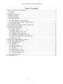
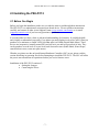
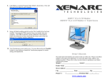
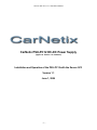
CarNetix PSU-PC12 V1.1 Installation Manual
CarNetix PSU-PC12 DC-DC Power Supply
(applies to Version 1.0+ hardware)
Installation and Operation of the PSU-PC12 with the Xenarc SC3
Version 1.1
June 1, 2006
-1-
CarNetix PSU-PC12 V1.1 Installation Manual
Table of Contents
1.0 PSU-PC12 Installation Instructions ................................................................................................ 4
1.1 Overview..................................................................................................................................... 4
1.2 Features....................................................................................................................................... 6
2.0 Installing the PSU-PC12................................................................................................................. 7
2.1 Before You Begin ....................................................................................................................... 7
2.2 Setting the Jumpers..................................................................................................................... 8
JP1 Jumper Settings...................................................................................................................... 9
JP3 Jumper Settings (+5V Always ON) ....................................................................................... 9
JP4 Jumper Settings (Secondary Output Control) ........................................................................ 9
2.3 Connecting the Wires................................................................................................................ 11
2.4 Optionally Connecting the Xenarc LCD Screen....................................................................... 14
3.0 Using the Pulse Start Feature........................................................................................................ 17
3.1 Pulse Start Connections ............................................................................................................ 17
3.2 Pulse Start Operation ................................................................................................................ 17
3.2.1 What is a pulse? ................................................................................................................. 17
3.2.2 Starting the PSU with a pulse ............................................................................................ 18
3.2.3 Stopping the PSU with a pulse .......................................................................................... 18
3.2.4 Prolonging the Shutdown Delay State ............................................................................... 18
3.2.5 Shutting down the PSU with double pulses....................................................................... 18
3.2.6 Ignition Override................................................................................................................ 18
4.0 PSU-PC12 Startup/Shutdown Controller...................................................................................... 19
4.1 Hibernate/Standby Operation ................................................................................................... 19
4.2 SSC Operation States................................................................................................................ 19
4.2.1 Idle State ............................................................................................................................ 19
4.2.2 RunDelay State .................................................................................................................. 19
4.2.3 Bootup Lockout State ........................................................................................................ 20
4.2.4 Run State............................................................................................................................ 20
4.2.5 Shutdown Delay State........................................................................................................ 20
4.2.6 Shutdown Sequence State.................................................................................................. 20
4.2.7 Forced Shutdown State ...................................................................................................... 21
4.3 Fault Indicator LEDS................................................................................................................ 21
5.0 Conditions of Use ......................................................................................................................... 24
-2-
CarNetix PSU-PC12 V1.1 Installation Manual
Summary of Notices & Disclaimers
CarNetix limited warranty is contingent upon proper and normal use and installation, and
does not cover damage due to external causes, including but not limited to, accident,
problems with electrical power, improper installation techniques or materials, liquids,
chemicals, oxidation, corrosion, exposure to the elements, servicing not authorized by
CarNetix, usage not in accordance with product instructions or specifications, failure to
perform required preventive maintenance, and problems caused by use of parts and
components not supplied by CarNetix.
CarNetix makes no express warranties or conditions beyond those stated in this warranty
statement. CarNetix disclaims all other warranties and conditions, express or implied,
including without limitation implied warranties and conditions of merchantability and fitness
for a particular purpose. Some states do not allow limitations on how long an implied
warranty lasts, so the above limitation may not apply to you.
CarNetix does not accept liability beyond the remedies set forth in this warranty statement
or liability for incidental or consequential damages, including without limitation any liability
for products not being available for use or for lost data or software.
CarNetix full warranty and return policies are stated in Section 6 at the end of this
document.
-3-
CarNetix PSU-PC12 V1.1 Installation Manual
1.0 PSU-PC12 Installation Instructions
NOTE: This manual and feature set apply to Rev 1.0 and above of the printed circuit board (PCB).
The PCB revision number is printed on the top of the PCB in white lettering. Please make sure you
are using the correct manual for the correct product revision.
1.1 Overview
The PSU-PC12 is a 90 watt intelligent DC-DC power regulator designed to provide safe, reliable
power to the Xenarc SC3.
Figure 1 CarNetix PSU-PC12
The PSU-PC12 provides two outputs. The primary output is +12V and can provide up to 6.3 amps
(75 Watts). The secondary output is +5V to power USB devices (such as the Audigy 2NX sound
USB sound card) with up to 3 amps (15 Watts). The PSU-PC12 can accept battery input as low as 7
volts under full load (90 watts) during cranking while providing a well-regulated output so that your
Xenarc SC3 does not crash.
-4-
CarNetix PSU-PC12 V1.1 Installation Manual
The PSU-PC12 includes an internal relay to control the ACPI interface of the Xenarc SC3. No more
soldering an external relay between the PSU-PC12 and the Xenarc SC3!
The PSU-PC12 includes all of the sophisticated features of its predecessors (P1260 and P1280) such
as Startup/Shutdown controller, Pulse Start (remotely start the PSU-PC12 with door locks, car alarm,
or wireless device), and DelayON (prevents speaker "thump" during booting). The PSU-PC12 fully
and safely supports "Standby" mode and will automatically shut itself down (by detecting excess
current drain) if the Xenarc SC3 fails to properly go into Standby mode.
The PSU-PC12 includes a power cable for “plug and play” installation with the Xenarc SC8
computer. This simplifies the installation and provides a safe, reliable connection for your Xenarc
SC3.
Figure 2 PSU-PC12 Power Cable
-5-
CarNetix PSU-PC12 V1.1 Installation Manual
1.2 Features
•
•
•
•
•
•
•
•
•
•
•
•
•
•
•
•
•
90 Watt Dual Output Regulator
Main output of +12V @ 6.3 Amps
Secondary output of +5V @ 3 Amps
Survives Engine Cranking under full load over entire temperature range
Includes sophisticated Startup/Shutdown Controller
INCLUDES INTERNAL ACPI RELAY Xenarc PC compatibility
Includes sturdy aluminum chassis with variable speed fan suitable for car
environment
Field upgradeable flash microprocessor
Low battery monitor prevents drained battery, even during Standby
"Anti Thump" delayed remote control for audio amplifiers
Remote "Pulse Start" from wireless device or car alarm/remote start system
Over current protection on both outputs with graceful forced shutdown of main
output
Powers both your Xenarc SC3 AND your screen or USB devices
Full, safe support for Windows Standby mode including auto shutdown if PC fails to
shutdown
Over voltage surge suppression on battery input for protection of harsh automotive
environment
User replaceable fuse on battery input to protect your car from internal short circuits
Very compact design measuring just 4.6" x 3.25" x 1.75" (L x W x H) or 117mm x 83mm x
45mm
-6-
CarNetix PSU-PC12 V1.1 Installation Manual
2.0 Installing the PSU-PC12
2.1 Before You Begin
Before you begin the installation, make sure you take the time to read through these instructions.
The PSU-PC12 is a sophisticated, microprocessor-based device. Please read these instructions
carefully and contact us either in our Support Forum (www.carnetix.com/forum) or via email
([email protected]) if you have any questions or problems.
It is assumed that you have a basic to advanced understanding of electronics. It would be helpful,
and is highly recommended (especially if you plan to get much further involved in CarPCs) that you
purchase, as a minimum, a simple VOM (volt-ohm meter) or DMM (Digital Multi-Meter). These
devices are inexpensive (starting around $20) and will save you and me a great deal of time. They
can be purchase over the web or at your local retail electronics store (Radio Shack, Home Depot,
some hardware stores, some auto parts stores).
Whether you plan to use the on-board Startup/Shutdown Controller (SSC) or not, please read the
section describing its operation first, before attempting to install the PSU-PC12. The SSC will affect
the power turn-on and turn-off operation whether you use its features or not.
Installation of the PSU-PC12 consists of :
• Setting the Jumpers
• Connecting the Wires.
-7-
CarNetix PSU-PC12 V1.1 Installation Manual
2.2 Setting the Jumpers
There are 3 user settable jumpers on the PSU-PC12. Below is a picture of their location on the
board. You will need to remove the 4 screws that hold the lid, remove the lid, and disconnect the fan
wire to get access the jumpers. Once you have selected your desired jumper positions, replace the
fan wire (note polarity of connector), replace the lid, and replace the 4 lid screws. Be careful not to
pinch the wire or let the fan wire touch the blades of the fan as your replace the lid.
Jumper
JP1
JP3
JP4
JP-1
JP-4
Functions
Pulse Start Input
Shutdown Delay Time
Hibernate/Standby
DelayOn Option
+5V Always On
Secondary Output Control
Figure 3 Jumper Location
-8-
JP-3
CarNetix PSU-PC12 V1.1 Installation Manual
JP1 Jumper Settings
Below is a table with the jumper selectable options for JP1. To move a jumper from its factory
default (open) position, use a pair of tweezers or needle nose pliers. Be careful to place the jumper in
the correct position or erratic behavior could result. Double-check your settings before replacing the
lid.
1-2
Function
Open
(default)
Jumpered
Pulse Start
Input
Connect to
external
contact
closure
Connect to
external
contact
closure
JP1 Jumper Pin Assignments
Pins
3-4
5-6
7-8
Shutdown
Hibernate/
Not Used
Delay
Standby
Time
9-10
DelayOn
Option
6 Seconds
Hibernate
Not Used
DLYON
follows IGN
15 minutes
Standby
Not Used
DLYON
follows PSU
Table 1 JP1 Settings
JP3 Jumper Settings (+5V Always ON)
For those users who want to keep +5V USB devices powered even when the Xenarc SC3 is OFF or
in Standby, you can jumper Pin1 to Pin 2 on JP3. This will keep the +5V regulator ON at all times,
even if the PSU-PC12 is OFF. Use caution when using this jumper position since it may cause your
battery to drain quickly.
JP4 Jumper Settings (Secondary Output Control)
The JP4 jumper gives you the flexibility to use the Secondary Output in different ways depending
upon your Xenarc SC3 system configuration. The Secondary Output can be turned on or off based
on two different control signals: 1) DLYON or, 2) the signal that controls the Primary Output (PRI
OUT).
• DLYON
Jumpering DLYON will turn your Secondary Output ON or OFF with the DLYON signal. This
means that your Secondary Output will come on 3 seconds after your Primary Output comes ON,
and will go off when you turn your ignition switch OFF.
-9-
CarNetix PSU-PC12 V1.1 Installation Manual
• PRI OUT
Jumpering PRI OUT will make the Secondary Output follow the control used to turn ON and OFF
the Primary Output. Thus, when the Primary Output is ON, the Secondary Output will also be ON. If
the Primary Output is OFF, the Secondary Output will be OFF.
This setting is affected by the jumper setting of the Shutdown Delay jumper on JP1. If you have set
the Shutdown Delay jumper to the default position (6 seconds), both the Primary and Secondary
Outputs will be turned OFF 6 seconds after the Ignition is turned OFF. If you have set the Shutdown
Delay jumper for 1 minutes, both the Primary and Secondary Outputs will remain ON for 1 minutes
after the Ignition is turned off. This setting is useful for keeping certain USB devices powered
during the Shutdown Delay time. For example, if you use the Secondary Output to power your USB
sound card and you want to keep your sound card powered during the Shutdown Delay time
(1minutes), then set the jumper JP4 for PRI OUT. Another application might be to keep a USB WiFi
card powered during Shutdown Delay for file transfer.
Follows PRI OUT
Follows DLYON
Once the jumper selections have been made you may begin installing the wiring to connect the PSUPC12 to your car’s electrical system, and to your Xenarc SC3.
- 10 -
CarNetix PSU-PC12 V1.1 Installation Manual
2.3 Connecting the Wires
After you have set the jumpers for the options and performance of the PSU-PC12 you can connect
the input and output wiring. The steps outline below should be followed to insure proper operation
of the PSU-PC12 and Xenarc SC3.
Step 1 – Connect the input power and ignition to the PSU-PC12.
Use heavy gauge wire directly connected to the battery (via 15A fuse and distribution block).
4-8 GA wire is recommended if the SC3 runs a 2-3GHz processor. 8-10 GA wire is
recommended for lower speed processors. Using wire that is too small will cause the SC3 to
not survive engine cranking.
Step 2 – Connect Ground to the PSU-PC12.
We recommend that you either run another wire directly to the battery, or connect directly to
the car chassis for grounding the PSU-PC12. If you run a wire to the battery, make sure it is
that same size as your +12V battery wire used in step 1. If you run a ground wire to the car’s
chassis, make sure to find a secure ground that is not corroded or painted and use the same
size wire as your +12V battery wire used in step 1.
Step 3 – Install optional Valet Switch.
A simple SPST switch installed in series with the ignition wire will allow you to manually
disable the PSU-PC12 so that it does not come on when the ignition is turned on. This is
optional and for convenience only.
- 11 -
CarNetix PSU-PC12 V1.1 Installation Manual
Step 4 – Connect the PSU-PC12 power cable
The the PSU-PC12 includes a power cable for interconnecting the Xenarc SC3 and the PSUPC12. Insert the cable into the J2 connector (white 6-pin Molex connector) of the PSU-PC12.
Do not plug the other end of this cable into the SC3 yet.
Step 5 – Test the PSU-PC12 before connecting the Xenarc SC3
It is recommended that you test the output of the PSU-PC12 before proceeding to the next
steps. Turn on the ignition and measure the voltage on the center pin of the round power
connector as shown in the diagram below. The voltage should read approximately +12.4
volts.
Figure 4 Measuring the PSU-PC-12 output voltage
Step 6 – Connect the CNX-CA-XSC8 power cable to the Xenarc SC8
Once you have tested for the presence of the proper voltage on the power connector, insert
both the Red/Black power connector and the Green/Black ACPI connector into the SC3 as
shown in the diagram below.
- 12 -
CarNetix PSU-PC12 V1.1 Installation Manual
The system is now ready to be connected to the other system peripherals.
- 13 -
CarNetix PSU-PC12 V1.1 Installation Manual
2.4 Optionally Connecting the Xenarc LCD Screen
The Xenarc LCD screen comes from the manufacturer with a cigarette lighter power
adapter so that it can be powered separately from the PSU-PC12. However, you can
optionally use PSU-PC12 to provide +12V regulated power to both the Xenarc SC3
AND the Xenarc LCD screen. Below are the steps you should follow if you choose to do
this. These steps assume that you have already installed the PSU-PC12/Xenarc SC3 using
power cable outlined in the previous section.
Connect the LCD screen power cable to the PSU-PC12 Primary Output
Here you have two options; 1) Cut off the Xenarc LCD screen cigarette adapter
and splice the screen power cable into the PSU-PC12 Primary Output. Or 2)
Purchase the optional CarNetix Screen Power Cable and splice it into the Primary
Output of the PSU-PC12.
The Primary Output of the PSU-PC12 appears on the RED wire of the power
cable. You should connect this RED Primary Output to the “+” (positive) lead of
your screen power cable. The “-“ (negative) lead of the screen power cable should
be splice into the BLACK ground wire of power cable. These connections are
show in the picture below.
- 14 -
CarNetix PSU-PC12 V1.1 Installation Manual
- 15 -
CarNetix PSU-PC12 V1.1 Installation Manual
2.5 Connecting to the +5V Secondary Output
The PSU-PC12 includes a +5V secondary output that can be used to provide power to
peripheral devices such as USB hubs or other USB devices such as the Audigy 2NX USB
sound card. The +5V secondary output is capable of providing up to 3 amps (15 watts).
The +5V secondary output appears on the white wire (Pin 1 of J2) and can be spliced as
described above for the LCD screen using T-taps. Below is a typical application diagram
using the +5V secondary output.
- 16 -
CarNetix PSU-PC12 V1.1 Installation Manual
3.0 Using the Pulse Start Feature
The PSU-PC12 includes a new feature that allows you to remotely start and stop the PSU.
This feature is called “Pulse Start”. This feature would normally be used in conjunction
with a wireless device such as a car alarm with auxiliary inputs/outputs or a WiFi device
with Wake-On-LAN (WOL) features.
3.1 Pulse Start Connections
The Pulse Start input can either be an externally applied voltage (ie +5v or +12V) pulse,
or a momentary relay contact closure. The externally applied voltage pulse is connected
to Pin 1 of J1 using the Blue wire. The momentary relay contact closure is connected to
Pins 1&2 of JP1 (see Section 2.2 for location). You can use either or both of these
connections to start/stop the PSU.
3.2 Pulse Start Operation
3.2.1 What is a pulse?
Voltage Pulse on Pin 1 of J1
When connecting to Pin 1 of J2, the “pulse” must be a voltage that transitions from 0V to
+V, and then transitions back to 0V. The SSC will wait (hang) if the voltage stays high
without going back to 0V after the initial transition from 0V to +V.
The value of the +V can be any voltage from approximately +2V to +20V. Typical
voltages are +5V or +12V. The value of 0V must be below +.2V or open circuit (ie you
could drive this input with a relay that momentarily connects to a +12V source and then
provides an open circuit).
The current required to drive this input is very low (milliamps).
Contact Closure Pulse on Pins 1&2 of JP1
When connecting to Pins 1&2 of JP1, the “pulse” must be a low resistance metallic
contact closure (ie relay) that transitions from OPEN to CLOSED, and then back to
OPEN. The SSC will wait (hang) if the contact closure remains CLOSED after the initial
transition from OPEN to CLOSED.
The current passing through this relay is very small (milliamps) so a low power relay can
be used.
Pulse Width
The pulse width can be any value from a minimum of approximately 100mSec to several
seconds. As mentioned above, if the pulse is very long the SSC will wait for the transition
back to the normal state before continuing.
- 17 -
CarNetix PSU-PC12 V1.1 Installation Manual
3.2.2 Starting the PSU with a pulse
When the PSU is in Idle State (both LEDs off) and an externally applied pulse is applied
to the Pulse Start input, the PSU will power up normally, as it would if the Ignition line
had gone high. During the Bootup Lockout State any input pulse is ignored.
3.2.3 Stopping the PSU with a pulse
After the normal power up sequence, and while in Runs State, the SSC monitors the
Pulse Start input for a shutdown pulse. If a single shutdown pulse is sensed, the PSU goes
into the Shutdown Delay State. However, if control has been passed to the Ignition line
(see Ignition Override below) the Pulse Start input is ignored.
3.2.4 Prolonging the Shutdown Delay State
If, while in the Shutdown Delay State, a single pulse is detected, the Shutdown Delay is
restarted at its original value in order to prolong the Shutdown Delay. This is useful for
occasionally downloading large files that would take longer than the normal Shutdown
Delay time.
Once the Shutdown Delay has timed out, the PSU enters the Shutdown Lockout State. At
this point the SSC ignores any pulse input until the PSU enters the Idle State.
3.2.5 Shutting down the PSU with double pulses
If two pulses are detected within a 5 second window during the Shutdown Delay State the
PSU will skip any remaining Shutdown Delay Time and immediately enter the Shutdown
Lockout Sequence. This feature is useful for shutting down the Xenarc SC3 when your
file transfer process is completed.
3.2.6 Ignition Override
If, after the PSU has been started by a pulse, the Ignition is turned on, control is passed to
the Ignition line. Once the Ignition line has gained control of the SSC it will be able to
shutdown the PSU as if it had initially started it. This feature is useful when you wish to
remotely start the Xenarc SC3 with your wireless device, but then get into your car and
drive.
- 18 -
CarNetix PSU-PC12 V1.1 Installation Manual
4.0 PSU-PC12 Startup/Shutdown Controller
The PSU-PC12 includes an intelligent, microprocessor-based startup/shutdown
controller. The PSU-PC12 Startup/Shutdown Controller (SSC) provides safe, reliable
control over your Xenarc SC3's bootup and shutdown (full shutdown or hibernation)
processes. The chief concerns of the SSC are protecting your hard drive from corruption,
protecting your car battery from being discharged, and protecting the PSU from
overheating.
4.1 Hibernate/Standby Operation
The PSU-PC12 supports both Hibernate and Standby operation of your Xenarc SC3. This
option is jumper selectable with Pins 5 & 6 on JP1.
When supporting Hibernation the PSU-PC12 completely shuts down all power to the
Xenarc SC3 after the Shutdown Lockout State. However, if Standby mode is selected, the
PSU-PC12 continues to provide +12V after the Shutdown Lockout State is completed,
but turns off its fans to conserve power. This has several very important ramifications.
1) In Standby your Xenarc SC3 continues to receive +12V power from the PSU-PC12 so
that it can retain the processor state in RAM. If for some reason the Xenarc SC3 did not
properly shut down when it received the ACPI shutdown pulse from the PSU-PC12, it
will continue to draw current from the PSU-PC12. . If this current exceeds approximately
1 amp the PSU-PC12 will automatically shut itself down.
2) Any USB devices connected to your Xenarc SC3 via the USB connector will continue
to draw current in the Standby state. THIS COULD POTENTIALLY DRAIN YOUR
BATTERY IF THE CURRENT DEMAND OF YOUR USB DEVICES IS VERY HIGH.
Exercise caution when using USB devices in the Standby mode.
.
4.2 SSC Operation States
4.2.1 Idle State
While idle, the SSC monitors your car battery while waiting for the ignition switch to be
turned on. If the battery is below approximately 10.5 volts, the SSC will not allow the
Xenarc SC3 to boot. If the battery is above 10.5 volts, the SSC will allow the Xenarc SC3
to boot normally.
4.2.2 RunDelay State
When you turn on your ignition, the SSC briefly (approx. 3 seconds) enters the RunDelay
state. During this time the SSC checks to make sure the battery is stable, the ignition
stays on, and then turns on its PSU output to the Xenarc SC3.
- 19 -
CarNetix PSU-PC12 V1.1 Installation Manual
4.2.3 Bootup Lockout State
After the Xenarc SC3 is powered, the ACPI (PWRON) strobe is sent to the motherboard.
At this point the SSC enters a "Lockout" state. In this state the SSC will not allow the
PSU to be turned off until after a jumper-selectable Lockout Time period. This state is
designed to prevent damage or corruption of a user's hard drive during bootup or
shutdown by premature loss of power. The Lockout Time is jumper-selectable at either
30 seconds or 90 seconds. This allows users who have configured their Xenarc SC3 for
hibernation to enjoy a faster shutdown sequence (30 seconds) than those who have their
Xenarc SC3 configured for full shutdown (90 seconds).
4.2.4 Run State
After the Lockout period ends, the SSC enters the Run state. During this time your
Xenarc SC3 is running normally and the SSC continues to monitor your car battery, the
PSU fan, and the output current. If the battery dips below approximately 10.5volts for
more than 10 seconds, or if the fan fails, or if the user is drawing more than the specified
maximum output current, the SSC enters a "ForcedShutdown" state (described below).
Under normal conditions, you exit the Run State either by turning off the ignition switch
or with a remotely applied pulse. After normally exiting the Run State, the SSC enters the
Shutdown Delay State.
4.2.5 Shutdown Delay State
After you turn off your ignition, or apply a remote pulse, the SSC enters a Shutdown
Delay state. This state allows you to keep your Xenarc SC3 running for a jumper
selectable time after the ignition is turned off. The selectable time periods are 6 seconds
(default) and 1 minutes. During this Shutdown Delay State, turning the ignition switch
back on will cause the SSC to re-enter the Run State and cancel the shutdown sequence.
Also, a remotely applied pulse can either prolong the Shutdown Delay State, or send the
PSU immediately into Shutdown Sequence State (see Section 6 Remote Start Pulse).
When this Shutdown Delay time has elapsed, the SSC enters the Shutdown Sequence
state (see below).
The SSC timing is designed to accommodate the use of the ACC wire instead of the IGN
wire to control the SSC. Note that during engine cranking, the ACC wire drops from
+12V to zero volts. The SSC has a minimum 6 second delay to accommodate this
temporary interruption in input voltage if the Xenarc SC3 was already running when you
start (or re-start) your engine. This delay will also give you time to briefly turn off the
ignition switch to stop your engine (ie at a gas station) and immediately turn the ignition
switch back on to keep the Xenarc SC3 running indefinitely.
4.2.6 Shutdown Sequence State
At the beginning of this state the SSC issues an ACPI (PWRON) strobe to the
motherboard. After the ACPI strobe is sent the SSC enters a Shutdown Lockout time
period, in which the SSC prevents the PSU from being turned on. This is to prevent the
SSC from issuing multiple ACPI strobes to the Xenarc SC3 motherboard while it is
shutting down. The Shutdown Lockout time is the same length as the Bootup Lockout
- 20 -
CarNetix PSU-PC12 V1.1 Installation Manual
time and is jumper-selectable for either 30 seconds or 90 seconds. After the Shutdown
Sequence State, the SSC re-enters the Idle State and waits for the ignition switch to be
turned on.
4.2.7 Forced Shutdown State
If the SSC detects either 1) a low battery (<10.5volts for >10seconds), 2) a fan fault, or 3)
an Over Current condition, the SSC enters a Forced Shutdown state. During this state the
SSC immediately begins a Shutdown Sequence without first entering the Shutdown
Delay State. The Shutdown Sequence cannot be exited by turning on (or leaving on) the
ignition. After a Forced Shutdown State is completed, the ignition switch must be turned
off to unlock the state and re-start the Xenarc SC3.
4.3 Fault Indicator LEDS
The PSU-PC12 has 2 LEDs that give an indication of the status and states of the SSC.
The pattern and blink-rates of these LED have different meanings depending upon what
state the SSC is in. Below is a link to the LED codes.
- 21 -
CarNetix PSU-PC12 V1.1 Installation Manual
PSU-PC12 Operation States
Normal Operation
PSU Output
LED1
LED2
State
Description
OFF
OFF
OFF
Idle State
PSU is idle and waiting for ignition/accessory switch to be
turned on. It is monitoring battery voltage during this time.
ON
Fast Blink
OFF
Run Delay State
PSU is on and waiting for output voltages to stabilize before
turning on Xenarc SC3
ON
ON
ON
Bootup Lockout
PSU is on and has sent ACPI pulse to motherboard. No
changes can occur until after boot period. This time period is
jumper selectable at either 30 sec (boot from hibernation) or 60
sec (full boot).
ON
ON
OFF
Run State
PSU is on and motherboard is running. No faults have been
detected.
Shutdown Delay
PSU is waiting before going into shutdown cycle. This delay
period is jumper selectable for 6 sec (default) or 1min. After this
delay PSU goes into shutdown Lockout state.
ON
ON
BLINK10%* OFF
BLINK50%* OFF
- 22 -
PSU is in the process of shutting down and has sent ACPI pulse
to motherboard. No changes can occur until after shutdown
lockout period (same as Boot Lockout period, 30sec or 60sec,
Shutdown Lockout
jumper selectable). After Shutdown Lockout state, PSU shuts
down power and goes into Idle State, waiting for IGN/ACC to be
turned on.
CarNetix PSU-PC12 V1.1 Installation Manual
Fault Conditions
PSU Power
LED1
LED2
OFF
OFF
ON
Low Battery/IGN
OFF
OFF
BLINK10%*
ON
Low battery voltage detected (<10.6V) and IGN/ACC switch is
Low Battery/IGN
on, or remote pulse has attempted to start PSU. PSU will not
ON
start unless battery voltage is greater than 10.6V.
ON
ON
OFF
BLINK10%*
ON
BLINK50%* BLINK50%
BLINK10%*
ON
Low battery voltage detected (<10.6V). PSU will not start
unless battery voltage is greater than 10.6V.
Major Fault
Pending
Low battery, Fan Fault, or over current condition is detected.
PSU will wait 10 seconds for condition to clear. If condition
persists for more than 10 seconds, PSU goes into Forced
Shutdown state.
Forced
Shutdown
A major fault has occurred (persistent low battery, fan fault,
over current fault) and the PSU is in Forced Shutdown state.
There is no Shutdown Delay before shutdown begins.
Shutdown time is set by Shutdown Lockout jumper setting
(30sec or 90sec). Once Forced Shutdown begins, clearing the
fault condition will not abort the Forced Shutdown cycle. After
Forced Shutdown, PSU waits for IGN/ACC switch to be turned
off, then on, before it will attempt to restart.
Abnormal
Shutdown
A major fault has occurred (persistent low battery, fan fault,
over temperature fault) and the PSU was forced to shutdown.
IGN/ACC switch must be turned off, then back on, before PSU
will attempt to restart. You should check the status of the
battery, fan, and ventilation if this fault occurs.
* BLINK10% means that the LED is on 10% of the time and off 90% of the time (ie, short blink).
* BLINK50% means that the LED is on 50% of the time and off 50% of the time.
Table 2 Status/Fault Indicator LED
- 23 -
CarNetix PSU-PC12 V1.1 Installation Manual
5.0 Conditions of Use
90-Day Limited Warranty
CarNetix warrants that the products it manufactures will be free from defects in materials and
workmanship. The warranty term for all products is 90 days beginning on the date of invoice. During
the warranty period CarNetix will repair or replace, at our discretion, products covered under this
limited warranty that are returned to CarNetix using a valid RMA number.
Service & Support
CarNetix provides a free on-line technical support forum for diagnosing hardware problems with your
system throughout the warranty period. Free technical support service is limited to configuration and
operation of hardware sold by CarNetix.
Returning Merchandise
If we determine that a part is defective a replacement can be after Purchaser obtains a Return
Merchandise Authorization (RMA) number. Purchaser must first contact us to obtain an RMA number
before attempting to return any part. Parts returned without first obtaining an RMA number shall not
be accepted, repaired, or replaced.
To obtain an RMA number, Purchaser must follow these procedures
1. Email us at [email protected] to receive your RMA number;
2. The RMA Number must be used within TEN (10) DAYS, or it will not be honored;
3. The RMA Number MUST BE SHOWN CLEARLY ON YOUR SHIPPING LABEL;
4. CarNetix must receive all Returns before a replacement will be sent, unless a valid credit card
number has been given to secure payment for the replacement part;
5. Include a copy of the Invoice on which the product(s) was shipped to you;
6. All RMA Returns must be shipped to CarNetix with freight PREPAID. Any Returns with freight
collect or COD will be refused and returned to you;
7. CarNetix must RECEIVE all returned goods within the warranty period.
CarNetix can send the replacement part before you return the defective part if you provide us with
your valid credit card number to cover the cost of the replacement. You must return the defective
part within fourteen (14) days from date of delivery of the new part, or your credit card will be
charged for the cost of the replacement part. Please retain your shipping information, including
tracking number. This will serve as your proof of return. A replacement part will be sent to you after
we receive the defective part from you if you cannot provide us with a valid credit card number.
Limitation Of Liability
This limited warranty is contingent upon proper and normal use and installation, and does not cover
damage due to external causes, including but not limited to, accident, problems with electrical power,
improper installation techniques or materials, liquids, chemicals, oxidation, corrosion, exposure to the
elements, servicing not authorized by CarNetix, usage not in accordance with product instructions or
specifications, failure to perform required preventive maintenance, and problems caused by use of
parts and components not supplied by CarNetix.
CarNetix makes no express warranties or conditions beyond those stated in this warranty statement.
CarNetix disclaims all other warranties and conditions, express or implied, including without limitation
implied warranties and conditions of merchantability and fitness for a particular purpose.
Some states do not allow limitations on how long an implied warranty lasts, so the above limitation
may not apply to you.
- 24 -
CarNetix PSU-PC12 V1.1 Installation Manual
CarNetix does not accept liability beyond the remedies set forth in this warranty statement or liability
for incidental or consequential damages, including without limitation any liability for products not
being available for use or for lost data or software.
Shipping & Returns
Shipping Locations and Methods
We ship both domestically (via UPS) and to most international locations (via USPS). Shipping charges do not
include import taxes or customs fees. We are not responsible for loss or damage to uninsured packages. If you
have a special shipping requirement or request, please notify us when you place your order or via email at
[email protected].
Return Shipping Policy
The Purchaser must pre-pay shipping and costs including insurance for any defective system or parts returned
under our warranty. CarNetix shall not be liable for risk of loss or damage during shipment of your returned
system or parts if you fail to insure the shipment. All products must be shipped back to CarNetix in their original
or equivalent packaging. CarNetix will ship the repaired or replacement product(s) to Purchaser via Ground
Service (freight prepaid) if you use an address in the continental United States. For shipments to other locations,
Purchaser must pre-pay any shipping charges, insurance, export taxes, custom duties and taxes including VAT
taxes, or any other charges associated with transportation of your CarNetix products. Purchaser assumes the
risk of loss. CarNetix shall not be responsible for failure of the delivery service to make on-time delivery. If
Purchaser requests a shipping method other than Ground Service, Purchaser must pre-pay the difference in cost
before CarNetix will ship the replacement product.
Product Return Policy
If you are an end-user customer who purchased products directly from CarNetix, you may return the product to
CarNetix within thirty (30) days of the purchase date for a refund of the purchase amount minus a 15% restocking fee. Shipping charges and insurance are not included and will not be refunded to you.
Returned products must be in as-new condition, and include all components, cables and all other items that were
included with product. Failure to meet this requirement will result in an additional 10% restocking fee (25% total)
being deducted from your refund. You must follow the conditions outlined below in order to obtain your refund:
Before any return, an RMA number must be obtained from CarNetix in accordance with the aforementioned RMA
Policy.
To receive a refund, the returned product must be received at our factory within fourteen (14) days from the date
that the RMA is issued and within thirty (30) days from the purchase date. If your product is not received within
fourteen (14) days of the RMA being issued, but it is received within thirty (30) days of your purchase date, then
you shall be charged 25% of your invoice amount as a restocking fee. If your product is not received within thirty
(30) days of your purchase date, then you shall not be entitled to any refund.
Upon CarNetix receipt of your returned product and verification that same has not been damaged, altered or is
missing any other original shipping items, you will receive a refund minus re-stocking fee, normally within
fourteen (14) days from the date the system is received. Your refund amount will be reduced for any missing
parts, components, other original shipping items or damage or alteration to the product. CarNetix will not accept
any unauthorized returns. Any merchandise returned without first obtaining an RMA number shall be rejected and
returned to you at your expense.
- 25 -