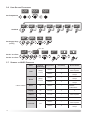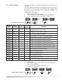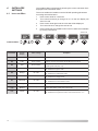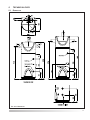
1
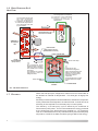
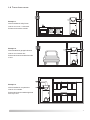
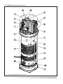
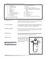
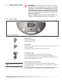
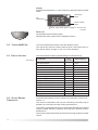
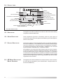
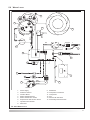
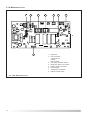
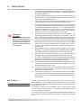
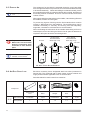
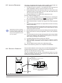
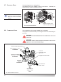
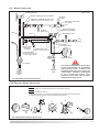
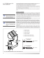
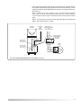
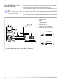
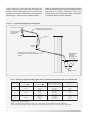
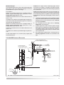
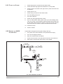
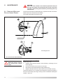
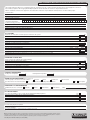
Instructions for Installation, Servicing and Use External Air Source Heat Pump Water Heater NUOS FS 200 NUOS FSi 250 1 Country of Destination: GB/IE IMPORTANT PLEASE READ The NUOS External Source Air Heat Pump Water Heater is intended for DOMESTIC USE ONLY. The NUOS is supplied in two cartons:Carton 1 contains the NUOS appliance. Carton 2 contains the fittings kit. Check labels on the cartons to ensure correct NUOS unit has been delivered BEFORE opening the cartons. The cardboard cartons which protect the unit should not be removed until installation. Store the wrapped unit upright in a safe dry space away from frost until required. Do not stack goods on the carton. Do not dispose of the carton until AFTER installation. The carton can be recycled. RECOMMENDED LIFTING Model NUOS Weight Fittings Kit kg (max) NUOS FS 200 90 5 NUOS FSi 250 110 6.5 It is recommended to use a sack barrow for lifting and moving the packaged NUOS. The bottom and top of the carton has polystyrene padding to protect the unit. Carrying the NUOS will require two fit persons. IMPORTANT The appliance should be kept in a vertical position when transported or stored. During manual handling it can be carried at an angle (i.e. in a sack barrow) or horizontally. If handling entails moving the product in a position other than vertical, wait at least 3 hours before starting the appliance once it is in the correct vertical position. This will ensure that the lubricating oil in the refrigeration circuit is correctly placed in order to avoid the compressor becoming damaged. IMPORTANT Failure to follow these instructions correctly may invalidate the guarantee. IMPORTANT The NUOS External Air Source Heat Pump Water Heater is an UNVENTED HOT WATER SYSTEM. Unvented domestic hot water heating systems must be installed to comply with the current Building Regulations, British Standards and any applicable local regulations. IMPORTANT Hard Water. Where the mains total water hardness exceeds 200 ppm, provision should be made to treat the feed water to reduce the rate of limescale accumulation. IMPORTANT - The Benchmark Scheme Benchmark places responsibilities on both manufacturers and installers. The purpose is to ensure that customers are provided with the correct equipment for their needs, that it is installed, commissioned and serviced in accordance with the manufacturer’s instructions by competent persons and that it meets the requirements of the appropriate Building Regulations. The Benchmark Checklist can be used to demonstrate compliance with Building Regulations and should be provided to the customer for future reference. Installers are required to carry out installation, commissioning and servicing work in accordance with the Benchmark Code of Practice which is available from the Heating and Hot Water Industry Council who manage and promote the Scheme. Visit www.centralheating.co.uk for more information. 2 TABLE OF CONTENTS IMPORTANT INFORMATION ..................... 2 1. GENERAL INFORMATION ................ 4 1.1 GUARANTEE .......................................... 4 1.2 INTENDED USE ....................................... 4 1.3 PERSONAL RESPONSIBILITY ...................... 4 1.4 CE MARKING ........................................ 5 1.5 THIS MANUAL ........................................ 5 1.6 BASIC PRINCIPLES OF A HEAT PUMP .......... 6 1.7 EFFICIENCY ........................................... 6 1.8 TYPICAL INSTALLATIONS ........................... 7 1.9 NUOS COMPONENTS IDENTIFICATION ........ 8 1.10 GENERAL LAYOUT .................................. 9 1.11 STORAGE VESSEL .................................. 9 1.12 HEATING ELEMENT ................................. 9 1.13 SUPPLY AIR ........................................... 9 1.14 EXHAUST AIR ........................................ 9 2. 2.1 2.2 2.3 2.4 2.5 2.6 SAFETY ........................................... 10 FLOOR MOUNTING ................................ 10 ELECTRICAL ........................................ 10 UNVENTED .......................................... 10 PERSONAL PROTECTION ........................ 10 TRANSPORTATION ................................. 10 REFRIGERANT ...................................... 10 3. 3.1 3.2 3.3 3.4 3.5 3.6 3.7 3.8 USER INSTRUCTIONS ................... 11 CONTROL PANEL .................................. 11 TURNING NUOS ON ............................ 12 DEFAULT SETTINGS ............................... 12 SETTING DESIRED TEMPERATURE ............ 12 SETTING OPERATING MODE ................... 13 USER SETTING PROCEDURES ................. 14 SUMMARY OF NUOS OPERATION ........... 14 INFORMATION MENU .............................. 15 4. INSTALLER’S SETTINGS ............... 16 4.1 INSTALLERS MENU ................................ 16 5. 5.1 5.2 5.3 5.4 5.5 5.6 5.7 TECHNICAL DATA .......................... 17 DIMENSIONS ........................................ 17 TECHNICAL DATA .................................. 18 KIT CONTENTS ..................................... 19 PRODUCT LABEL .................................. 20 REGULATIONS ...................................... 20 WATER REGULATIONS ........................... 20 BUILDING REGULATIONS ......................... 20 5.8 IEE WIRING REGULATIONS/BRITISH STANDARDS ......................................... 20 5.9 WIRING LAYOUT ................................... 21 5.10 MAINBOARD LAYOUT ............................. 22 6. 6.1 6.2 6.3 6.4 6.5 6.6 6.7 6.8 6.9 6.10 6.11 6.12 6.13 6.14 6.15 6.16 6.17 6.18 6.19 6.20 6.21 6.22 6.23 INSTALLATION ................................ 23 LOCATION OF THE APPLIANCE ................. 23 AIR SUPPLY ........................................ 23 EXHAUST AIR ...................................... 24 AIR DUCT STATIC LOSS ........................ 24 INSTALLING PROCEDURE ........................ 25 ELECTRICAL CONNECTION ...................... 25 BATHROOM ZONES ............................... 26 COMBINATION VALVE ............................. 26 WATER CONNECTIONS .......................... 27 EXPANSION VESSEL INSTALLATION ........... 27 FSI 250 SOLAR CONNECTION ................ 28 FSI 250 BOILER CONNECTION ............... 30 TPRV & PRV DISCHARGE ................... 31 TPRV & PRV DISCHARGE TO GULLY .... 31 BUILDING REGULATIONS G3 ................... 31 NUOS EXPANSION DISCHARGE ............. 33 SUPPORTING FLOOR ............................. 34 POSITIONING THE UNIT .......................... 34 LEVELLING THE UNIT ............................. 34 FIXING THE UNIT .................................. 34 CONDENSATE OUTLET ........................... 34 FILLING THE SYSTEM ............................. 35 DRAINING THE NUOS CYLINDER UNIT .... 35 7. COMMISSIONING SYSTEM ........... 36 7.1 COMMISSIONING PROCEDURE ................. 36 8. MAINTENANCE............................... 38 8.1 REMOVING & REPLACING ELECTRIC HEATER ELEMENT ................................ 38 8.2 ROUTINE MAINTENANCE ........................ 39 8.3 ERROR CODES .................................... 40 8.4 FAULT FINDING .................................... 41 9. BENCHMARK LOGBOOK ............... 42 TERMS AND CONDITIONS OF GUARANTEE .......... 44 LEAVE THESE INSTRUCTIONS WITH THE END USER 3 1. GENERAL INFORMATION This manual is an integral and essential part of the product. It should be kept with the product. Please read carefully the instructions and notes about Ariston NUOS Heat Pump Water Heater contained in this manual as they provide important information regarding the safe installation of the system. WARNING Warnings emphasize that a potentially hazardous or dangerous situation could exist. Serious injury or death is possible if warning instructions are not obeyed. CAUTION Indicates precautions that if not taken could result in damage, malfunction, or abnormal operation of the equipment. IMPORTANT Text headed ‘Important’ refers to vital information that should be noted about the equipment, its use, maintenance or warranty. NOTE Notes are used to give additional information, understanding or to highlight a certain point. They may also be used for referrals. 1.1 GUARANTEE The Ariston External Air Source Heat Pump Water Heater is guaranteed for 5 Years (Tank) and 2 Years (electrical components) against manufacturing defect - see terms and conditions of guarantee on back page. The manufacturers shall not be held liable for any damage due to faulty installation, improper or incorrect use or uses that are not reasonably predictable. The guarantee is subject to: 1. The appliance being correctly installed and commissioned, as detailed in this manual. 2. The appliance being annually serviced as detailed in this manual. 1.2 INTENDED USE This appliance is intended for the production of domestic hot water at temperatures up to 65°C. The appliance must be correctly connected to a domestic cold mains water supply. Electric power is required. The appliance must not be used for any other purpose or industrial process. 1.3 PERSONAL RESPONSIBILITY 4 The manufacturer is responsible for the product’s conformity to the relevant construction directives, laws and regulations in force at the time the product is first commercialised. The Plumbing Engineer/Electrician/Installer and user are each exclusively responsible in their respective fields, for knowing and observing the legal requirements and technical regulations concerning the design, installation, operation and maintenance of the appliance. Reference to laws, regulations or technical specifications contained in this manual is purely for information purposes; any new laws introduced or modifications to existing laws are not in any way binding on the manufacturer towards third parties. 1.4 CE MARKING The CE marking applied to the appliance certifies that it conforms to the essential requirements of the following European Directives:2006/95/EC concerning the safety of electrical equipment. 2004/108/EC concerning electromagnetic compatibility. Checks are carried out in conformity with the following technical standards:EN 255-3; EN 60335-1; EN 60335-2-21; EN 60335-2-40; EN 55014-1; EN 61000-3-2; EN 61000-3-3; EN 50366. The manufacturer’s ability to manufacture and supply all products in conformity with the above mentioned regulations is guaranteed by a company quality management system that is certified according to the ISO 9001 2008 standard. 1.5 THIS MANUAL This NUOS manual is intended for:1. The installer 2. The end user. The manual is an integral and essential part of the product. It should be kept with the appliance so that it can be consulted by the user and/or authorised personnel. To ensure that the appliance is installed and used properly and safely, both the installers and user must carefully read the instructions and precautions contained in this manual as they provide important information for both their areas of competence, regarding safety, installation, use and maintenance of the appliance. This manual is divided into sections. Section 1 General Information This section is intended for both installers and users of the NUOS. It contains general information for the appliance, layout and description plus important information about the manual. Section 2 Safety Section 3 User Instructions The Installer, once the system is operating correctly, should demonstrate the NUOS operation with the aid of this section. Section 4 Installer’s Settings Installer’s control parameter settings. Section 5 Technical Data Generally intended for the specifier and installers including technical data, dimensions and special requirements. Section 6 Installation Includes information for the installing Plumbing Engineer and Electrician. Section 7 Commissioning System Essential information for the installer for the completion of the NUOS installation. Section 8 Maintenance Includes maintenance and fault finding. Section 9 Benchmark Logbook 5 1.6 BASIC PRINCIPLES OF A HEAT PUMP 1 2 The fan draws air through t h e h e a t e x c h a n g e r. The cool refrigerant is heated by the ambient or external air temperature. The refrigerant boils and turns to vapour. The compressor increases the pressure of the refrigerant vapour causing it to significantly increase in temperature REFRIGERANT IN SEALED SYSTEM AMBIENT or EXTERNAL AIR COMPRESSOR FAN PRESSURE REDUCING VALVE (EXPANSION VALVE) HIGH PRESSURE HEAT EXCHANGER (Evaporator) To hot water taps 4 The refrigerant liquid passes through a pressure reducing valve (changing from small bore to larger bore pipe). The reduction of pressure significantly cools the refrigerant fluid. 3 Heat from the hot pressurised refrigerant vapour is transferred to the water in the stored water vessel by a second heat exchanger called a condenser. As the refrigerant is cooled it reverts back to its liquid state. Cold Feed STORED WATER VESSEL CONDENSER FIG. 1.6A BASIC PRINCIPLES 1.7 EFFICIENCY Within the heat pump the refrigerant is warmed from its cooled state to the ambient or external air temperature. This heat gain is largely free energy. Electricity is used to power the fan which draws air, and also the compressor which pressurises the refrigerant to increase it’s heat. A small amount of electricity is also required to run the heat pump’s control system. The efficiency of a heat pump cycle is stated by its Coefficient of Performance (COP) value. This is a ratio between the energy produced by the heat pump to the electrical energy supplied to it. For example a COP of 3.0 indicates that for every 1kW of electricity used the heat pump will produce 3.0 kW of hot water, therefore giving 2.0kW of free energy. 6 1:8 TYPICAL INSTALLATIONS Example 1. NUOS installed in Utility Room. Inlet air from room - not ducted. Exhaust air ducted to outside. Example 2. NUOS installed in garage/outhouse. Inlet air from internal duct. Exhaust air ducted to outside from side of unit. Example 3. NUOS installed in compartment. Inlet air from outside. Exhaust air ducted to outside high level from top of unit. 7 1.9 NUOS COMPONENTS IDENTIFICATION FIG. 1.9A NUOS COMPONENTS IDENTIFICATION 8 1.9 NUOS COMPONENTS IDENTIFICATION 1. 2. 3. 4. 5. 6. 7. 8. 9. 10. 11. 12. NUOS Cylinder Air Fan Outlet - Side Air Fan Outlet - Top Air Fan Ambient Air Inlet Evaporator Compressor Compressor Condenser Thermostatic Expansion Valve Pressure Safety Switch Control Panel Condensate Drain Pipe CONTINUED 13. 14. 15. 16. 17. 18. 19. 20. 21. 22. DHW Temperature Sensor Anode Heat Exchanger (Condenser) Electric Heating Element and Heating Element Zone Sensors and Magnesium Anode Casing Height Adjustable Feet Top Cover Cylinder TPR Valve Product Label Manual Reset Overheat Stat (FSi 250 Only) NUOS COMPONENTS IDENTIFICATION LIST 1.10 GENERAL LAYOUT The NUOS water heater essentially comprises an upper compartment containing the heat pump assembly, a module which includes the control panel and control circuit boards, and a storage vessel. 1.11 STORAGE VESSEL The storage vessel is internally coated with protective enamel treatment and is externally insulated by a high efficiency polyurethane layer. The storage vessel is enclosed within a powder coated steel casing. 1.12 HEATING ELEMENT The heater element fits into the side of the storage vessel. It is electrically powered to heat the water to boost the heat pump performance or to heat the water when the heat pump is off. 1.13 SUPPLY AIR The air for the NUOS enters through a round vent at the rear of the unit. The air could be from within the room or ducted from another room, internal space within the dwelling or more typically from outside. 1.14 EXHAUST AIR The exhaust air for the appliance can be directly into the room, or, by using various ducting arrangements, be ducted to another room or more typically to outside the dwelling. For further considerations for supply and exhaust air refer to sections 6.2 and 6.3. Top Exhaust Air Supply Air Side Exhaust Air FIG. 1.14A AIR SUPPLY & EXHAUST 9 2. SAFETY 2.1 FLOOR MOUNTING The NUOS weights when full are:NUOS 200 - 290kg NUOS 250i - 360kg The floor on which the unit is to be standing must be capable of supporting (locally) the weight of the full unit. Do not install the cylinder on floors made of chipboard or other flooring where the mechanical strength is compromised when damp. 2.2 ELECTRICAL The NUOS should have 240V 10.8 amp electrical supply. All electrical terminal covers must be screwed on before power is switched on. The unit must be earthed. The pipework to and from the unit must be earth bonded. The unit must be protected by a 13 amp fuse. 2.3 UNVENTED The NUOS heat pump is classed as an unvented cylinder. It must be protected by a pressure relief valve (PRV) and expansion vessel as detailed in section 6.9. No valves must be fitted between the vessel and the PRV. No valves must be fitted between the vessel and its expansion vessel. 2.4 PERSONAL PROTECTION When installing and servicing the appliance Ariston Thermo UK Ltd. recommend the use of suitable protective clothing (i.e. gloves). 2.5 TRANSPORTATION It is recommended to use a sack barrow for lifting and moving the packaged NUOS. Also refer to page 2 Carrying the NUOS will require two fit persons. Always follow the safe lifting guidelines as recommended by the Health And Safety Executive www.hse.gov.uk. IMPORTANT The appliance should be kept in a vertical position when transported or stored. During manual handling it can be carried at an angle (i.e. in a sack barrow) or horizontally. If handling entails moving the product in a position other than vertical, wait at least 3 hours before starting the appliance once it is in the correct vertical position. This will ensure that the lubricating oil in the refrigeration circuit is correctly placed in order to avoid the compressor becoming damaged. 2.6 REFRIGERANT 10 Refer to Section 5.2 Technical Data 3. USER INSTRUCTIONS IMPORTANT This appliance is not intended for use by persons (including children) with reduced physical, sensory or mental capabilities, or lack of experience and knowledge, unless they have been given supervision or instruction concerning use of the appliance by a person responsible for their safety. Children should be supervised to ensure that they do not play with the appliance. Once the NUOS unit has been fully commissioned, the installer must give full guidance of use to the end user. 3.1 CONTROL PANEL HP AUTO set FIG. 3.1A CONTROL PANEL ON/OFF Button Press to turn NUOS ON. Press again to turn OFF. Mode Button Press to select mode either Auto, Boost and Green, Voyage, P1,P2 or P1+P2 (if enabled). Also press to exit from installer and information menus. Control Knob - User Turn knob clockwise to increase to desired set temperature. Turn knob anticlockwise to decrease to desired set temperature. Press and release knob and the current temperature of the water within the tank will be displayed for 5 seconds. For Installer Menu operation refer to 4.1. Control Knob - Information Menu Press and hold the knob for 5 seconds to display Information Menu. Turn knob clockwise / anticlockwise to scroll through information parameters L0 to L14. Press knob at selected parameter and it’s current value will be displayed. Press knob again (or mode button) to return to Information menu. 11 Display Displays set temperature °C, mode, heat pump status and electric heater status. Heat Pump active HP Set Temperature AUTO set Electric Heater active Mode - Auto, Boost, Green, Voyage P1, P2 or P1+P2 If enabled Smile Led ON indicates NUOS is heating water. Will also flash when system error is displayed, see 8.3. 3.2 TURNING NUOS ON To turn the NUOS ON and OFF, press the ON/OFF button. The unit will turn ON in the same mode as when it was turned OFF i.e. Auto, Boost, Green, Voyage, P1, P2 or P1+P2 (if enabled). 3.3 DEFAULT SETTINGS * See page 16 The NUOS has the following default settings on initial power up. Parameter Set Temperature Min. Settable Temp. Max Settable Temp.(with heat pump only) Mode - Auto Mode - Boost Mode - Green Mode - Voyage Mode - Programs P1 & P2 Programme P1 Temp. Programme P1 Time Programme P2 Temp. Programme P2 Time Antibacterial Function Defrost Time_W 3.4 SETTING DESIRED TEMPERATURE Installers Menu parameter* Default Setting P2 P3 P4 P6 P11 P5 P7 P9 55°C 50°C 55°C On - Enabled On - Enabled Off - Disabled Off - Disabled Off - Disabled 55°C 06:00hrs 55°C 18:00hrs Off - Disabled On - Enabled 8 hours The desired temperature for the hot water is set using the ‘Control knob’ refer to 3.1. The minimum temperature that can be achieved by the heat pump is between 40°C and 50°C this limit is set by parameter P2. The maximum temperature that can be achieved by the heat pump without using the heater element is between 50°C and 55°C this limit is set by parameter P3. The maximum temperature that can be achieved using the electric heater is 65°C. 12 3.5 SETTING OPERATING MODE The mode is set using the ‘Mode Button’ - refer to 3.1 Auto Mode The NUOS operates giving priority to the heat pump to reach the set temperature within a set time duration as determined by parameter P9 (default 8 hours). If the control calculates that the heat pump alone cannot achieve the set temperature within this time, then the heating element is used as economically as possible to achieve the set temperature. Boost Mode The NUOS operates with both heat pump and heating element to achieve the set temperature in the shortest time. Once the set temperature is reached the control switches to Auto mode. Note the heating element will still operate for defrost, antibacterial functions and when air temperature is out of operating range. Voyage Mode & Program Mode:In the event of a power failure the NUOS automatically switches to Auto Mode. P1 and P2 are not switch on times as normal water heating systems. The NUOS will start heating water depending on the ambient temperature to provide hot water at the set times for P1 and P2. The NUOS time setting must be correct for P1 and P2 to operate on time - see 3.8. Green Mode The NUOS will operate using only the heat pump to achieve the set temperature, without any time duration limit. This ensures maximum energy saving. This function is recommended for air temperatures above 0°C during the hours of heating. Green mode is enabled/disabled by installer menu parameter P4. The maximum temperature that can be achieved in green mode is between 50°C and 55°C this limit is set by parameter P3. Voyage (holiday) Mode Voyage mode is enabled/disabled by installer menu parameter P6. Voyage mode enables the user to set a number of days that the NUOS will not produce hot water. The defrost will remain if enabled by P7. The antibacterial function P5 will remain if enabled by P5. To set holiday days:1. Press ‘mode’ button until Voyage mode is displayed. 2. Turn control knob until the required number of days is displayed. 3. Press control knob to confirm. The display will show the number of holiday days remaining. When the set number of days have passed the NUOS will produce hot water again in Auto mode. Therefore to return home and have hot water available, set one day less than the days away. Program Mode Program mode is enabled/disabled by installer menu parameter P11. There are three programme modes P1, P2 and P1+P2. P1 Hot water will be available once per day @ P1 set time @ P1 set temperature. P2 Hot water will be available once per day @ P2 set time @ P2 set temperature. P1 + P2 Hot water will be available twice per day First @ P1 set time @ P1 set temperature. Second @ P2 set time @ P2 set temperature. To set P1 and P2 times and temperatures:1. Press ‘mode’ button until P1 mode is displayed. 2. Turn control knob until the required temperature is displayed. 3. Press control knob to confirm. 4. Turn control knob again until the required time is displayed. 5. Press control knob to confirm. Repeat above for P2. 13 3.6 USER SETTING PROCEDURES set set set Set Temperature set AUTO set set BOOST GREEN set VOYAGE P1 set P2 set set P1 + P2 Set Mode set AUTO set VOYAGE VOYAGE VOYAGE Set Voyage Days (holiday) Also ‘P2’ set AUTO P1 set P1 P1 P1 P1 Set P1 °C & Time Set P2 °C & Time 3.7 SUMMARY OF NUOS OPERATION Mode Auto B o o st * When enabled Always available Heat Pump Electric Heater 40-55°C ✓ ✓ When required 55-65°C ✕ ✓ Always 40-55°C ✓ ✓ Always 55-65°C ✕ ✓ Always Always available ✕ ✓ Defrost* ✓ Antibacterial* Green P4 40-55°C ✓ Voyage P6 5°C min ✕ ✕ Defrost P7 5°C min ✓ ✓ When required Antibacterial P5 65°C ✓ ✓ 40-55°C ✓ ✓ When required 55-65°C ✕ ✓ Always P 1 an d P 2 14 Enabled Temperature Disabled by: - P11 The Information Menu is displayed by pressing the control knob for 5 seconds. The menu displays operating function status and monitoring information. No changes can be made within the information menu (except current time L0), any other settings that can be changed are changed in the installers menu - see 4.1 Accessing Information Menu:1. Press control knob for 5 seconds. 2. Turn control knob until the required L number is displayed. 3. Press control knob to view current value / setting. 3.8 INFORMATION MENU HP AUTO set HC-HP L0 to L14 TW1 47°C Current Value Access Information Menu 5 seconds Information L ab el Screen Display Value Controlled by Parameter L0 hh:mm hh:mm P11 Displays current set time. Can be reset by turning knob. Only available when P11 is set to ON. L2 TIME_W Hours P9 Set maximum hours of NUOS operation L3 ANTI_B On or Off P5 Shows setting of antibacterial function. L4 T HP °C P3 Shows setting for the maximum heat pump temperature L5 T W1 °C - Displays current temperature recorded by sensor 1 L6 T W2 °C - Displays current temperature recorded by sensor 2 L7 T W3 °C - Displays current temperature recorded by dome sensor L8 T AIR °C - Displays current temperature recorded by air intake sensor L9 T EVAP °C - Displays current temperature recorded by evaporator sensor L 10 DEFROS On or Off - Shows setting of frost protection function. L11 HP h °C - Meter for internal parameter 1 L 12 HE h °C - Meter for internal parameter 2 L 13 SW MB ref - Main PCB software version L 14 SW HMI ref - Interface PCB software version PO C ode 222 P0 Decription Enables entry to installers menu, when correct code is selected To set current time 1. Press control knob for 5 seconds until L0 hh:mm is displayed. 2. Press control knob again 3. Turn control knob to change current time. 4. Press control knob again. HP AUTO set hh-mm hh-mm hh-mm Setting Current Time L0 5 seconds 15 4. The Installers Menu is displayed by entering the correct code when P0 is displayed in the information menu. INSTALLERS SETTINGS The menu enables the installer to set the NUOS operating parameters. 4.1 INSTALLERS MENU Accessing Information Menu:1. Press control knob for 5 seconds. 2. Turn control knob and go through L0 to L14 then the display will show P0 code. 3. Press control knob again and the code 222 will be displayed. 4. Turn control knob to change the code to 234. 5. Press control knob, the installers menu P2 to P11 will then be available by turning control knob. P2 to P11 HP AUTO set HC-HP CODE 222 234 T Min Installers Menu 5 seconds Parameter Screen Display Value / Range P0 CODE 234 P2 T Min 40°C to 50°C Sets the minimum temperature that the NUOS can be set to. P3 T HP 50°C to 55°C Sets the maximum obtainable temperature, when the NUOS is operating with heat pump only. P4 GREEN On / Off On - Enables the green mode see - 3.5 Off - Disables the 'green' mode P5 ANTI_B On / Off On - Enables the Antibacterial mode see - 3.5 Off - Disables the Antibacterial mode P6 VOYAGE On / Off On - Enables the Voyage mode see - 3.5 Off - Disables the Voyage mode P7 DEFROS On / Off On - Enables the Frost Protection mode Off - Disables the Frost Protection mode P9 TIME_W 5hours to 24hours P 10 RESET - P11 PROG On / Off 16 Decription Code required to enter installers menu Sets the permited number of operation hours for the NUOS Enables resetting of the NUOS default settings. Select parameter P10 and press control knob. On - Enables the Programmemode P1,P2 and P1+P2 see - 3.5 Off - Disables the Programme mode P1,P2 and P1+P2 see - 3.5 5. TECHNICAL DATA 5.1 DIMENSIONS FIG. 5.1A DIMENSIONS 17 5.2 TECHNICAL DATA Description Tank Rated Capacity Footprint (minimum) Height Weight Empty Weight Full Minimum ceiling height required Maximum Operating Pressure Condensate Drain Air Intake Air Exhaust Maximum Duct Static Loss * Cylinder - Tested in accordance with:Normal Operating Pressure Maximum Water Supply Pressure Cold Connection (feed) Hot Connection (draw off) Pressure Reducing Valve Set Pressure Cylinder TPRV Combination Valve PRV Expansion Vessel Pre-Charge Pressure Cylinder Indirect Coil Connections Surface Area Maximum Supply Pressure Rating @ 60°C Primary Flow Rate Pressure Drop through coil @15l/m Heat Pump Heat Rating** Power Consumption** COP** (see 1.7) Heating Time** Heating Energy Consumed** Max. Water in Single Intake V40 @ 55°C Max. Water in Single Intake V40 @ 62°C Max. Water Temperature Max. Current Consumption Expansion Valve Operating Pressure Refrigerant Fluid Type of Fluid Quantity Practical Limit for Room Volume*** Max. Pressure of Circuit - low side Max. Pressure of Condenser Coil Max. Pressure of Circuit - high side FS 200 200 litre 0.6 x 0.6m 1.70m 90kg 290kg 1.75m 6 bar ½” BSP F Ø150mm Ø150mm 70Pa BS6700 3.5 bar 12 bar ¾” BSP-22mm MI ¾” BSP-22mm MI 3.5 bar 90-95ºC / 7 bar 6 bar 3.5 bar FSi 250 250 litre 0.6 x 0.6m 1.96m 110kg 360kg 2m 6 bar ½” BSP F Ø150mm Ø150mm 70Pa EN 12897:2006 3.5 bar 12 bar ¾” BSP-22mm MI ¾” BSP-22mm MI 3.5 bar 90-95ºC / 7bar 6 bar 3.5 bar FSi 250 only ¾” BSP-22mm 0.65m² 6 bar 210.0 litres 15 l/min. 14 mbar 2.775 kW 0.75 kW 3.7 3h:10min. 2.2 kWh 260 litres 348 litres 55°C 3 amp 10-24 bar 2.775 kW 0.75 kW 3.7 3h:40min. 2.7 kWh 325 litres 435 litres 55°C 3 amp 10-24 bar R134a 1.28 kg 5.12m³ 1.0 MPa 24 bar 2.5 MPa R134a 1.28 kg 5.12m³ 1.0 MPa 24 bar 2.5 MPa *Maximum permissible static loss for both supply air duct and exhaust air duct, when applicable. **Values obtained with air temp. of 15°C and 37% relative humidity, input water temp. 15°C (in conformity to EN 255-3 specifications). ***The practical limit is the minimum room volume the appliance should be installed in, the volume is based on quantity of refrigerant in the system. In the event of a sudden release of refrigerant then the minimum room volume will make it safer for the engineer. 18 5.2 TECHNICAL DATA CONTINUED Description All models Electric Electric Supply Amp Connection Fuse Required Protection Bathroom Zone Electric Heater Rating Electric Heater Length Electric Heater Type Electric Heater Max. Temp. 220/240V, Single Phase, 50 Hz 10.8 amp 3 core flex supplied 1.2m long 13 amp IPX4 Zone 2 - Switches/Fuse Zone 3 kW1.5+1 470mm (1) 65°C Air Air Flow Rate Available Static Pressure Sound Level @ 1m Min. temp of room of installation Max. temp of room of installation Min. Volume of Room (non-ducted) Min. Air Temp Required (w.b.) @ 90% r.h. Max. Air Temp Required (w.b.) @ 90% r.h. 300 - 500 m³/h 70 Pa 56 dB(A) 1°C 35°C 20 m³ -5°C 35°C Description Reheat Time (▲T 45°C) mins Heat Pump only (Green Mode) @ 100% capacity Heat Pump only (Green Mode) @ 70% capacity Heat Pump & Heater (Boost Mode) @100% capacity Heat Pump & Heater (Boost Mode) @ 70% capacity Model time to raise 100% temp. from 15°C to 65°C Model time to raise 70% temp. from 15°C to 65°C Insulation Heat Loss @ 65ºC Ozone Depletion Potential (ODP) Global Warming Potential (GWP) 5.3 KIT CONTENTS FS 200 FSi 250 236 mins 181 mins 140 mins 114 mins 152 mins 124 mins 274 mins 2.06 kW/24hr 0 <5 2.05 kW/24hr 0 <5 Direct kit for NUOS FS 200 pt. no. 3069418 Qty 1 Pressure Reducing Valve Qty 1 Security Valve (6 bar) Qty 1 Tundish Qty 1 Expansion Vessel (18 litre) Direct kit for NUOS FSi 250 pt. no. 3069419 Qty 1 Pressure Reducing Valve Qty 1 Security Valve (6 bar) Qty 1 Tundish Qty 1 Expansion Vessel (18 litre) Qty 1 2 Port Motorised Valve 19 5.4 PRODUCT LABEL CAPACITY SERIAL NUMBER MODEL VOLTAGE / FREQUENCY MAXIMUM POWER CONSUMPTION MAX. TANK PRESSURE WEIGHT WHEN FULL TYPE/QUANTITY OF REFRIGERANT MAX PRESSURE HEAT PUMP CIRCUIT HI/LOW PRESSRE SIDE HEAT PUMP POWER CONSUMPTION HEAT PUMP HEAT RATING SYMBOLS IPX4 POWER CONSUMPTION ELECTRIC HEATING ELEMEMENT TANK PROTECTION IP RATING FIG. 5.4A PRODUCT LABEL 5.5 REGULATIONS The appliance should be installed in accordance with the Domestic Heating Compliance Guide and BS 3456. 5.6 WATER REGULATIONS These regulations (bye-laws in Scotland), ensure a good supply of wholesome water and that only approved materials, pipes and fittings are used to convey water. 5.7 BUILDING REGULATIONS These are a statutory document and take priority over all other regulations and recommendations. The installation of an unvented hot water storage cylinder is classified as a ‘Controlled Service’ and Regulation G3 applies. To meet the requirements of the Regulation, installation of an unvented system should be undertaken by a ‘competent installer’. All installations of unvented hot water storage systems having a capacity of more than 15 litres should be notified to the relevant Local Authority by means of building notice or by the submission of full plans. It is important to note that it is a criminal offence to install an unvented hot water storage system without notifying the Local Authority. The installation of the unvented cylinder and hot water system must comply with BS 6700 and the HSE Legionella Code of Practice. 5.8 IEE WIRING REGULATIONS/ BRITISH STANDARDS 20 The appliance should be installed in accordance with the current versions the IEE Wiring Regulations (now called BS7671 “Requirements for electrical installations”) 5.9 WIRING LAYOUT 7 11 R S 13 12 BLUE BLUE BLUE WHITE BROWN C 35uF 400V BLACK BLACK 10 U U 4 N BROWN L fuse 16AT N BLUE L 2 1 9 6 3x1,5V AA 8 2 3 14 1000W 4 c RED BLACK BLUE 5 1500W 1. 2. 3. 4. 5. 6. 7. 8. Power Supply DHW NTC Sensor Interface Board Electric Heater Element Electric Heater NTC Sensor Evaporator & Inlet Air NTC Sensor Cylinder Earth Terminal Serial Port 9. 10. 11. 12. 13. 14. Mainboard Compressor Condenser Compressor Fan Defrost Hot Gas Valve Gas Safety Pressure Switch FIG. 5.9A WIRING LAYOUT 21 5.10 MAINBOARD LAYOUT 2 9 8 6 5 3 7 4 E D C B A 2 1 1. 2. 3. 4. 5. 6. 7. 8. FIG. 5.10A MAINBOARD LAYOUT 22 Serial Port Fan Connection A and B to 12V C Earth D and E 240V Gas Safety Pressure Switch DHW NTC Sensor Connection Electric Heater Connection Power Supply Compressor Connection Defrost Hot Gas Valve 6. INSTALLATION 6.1 LOCATION OF THE APPLIANCE IMPORTANT Hard Water Where the mains total water hardness exceeds 200 ppm, provision should be made to treat the feed water to reduce the rate of limescale accumulation. 6.2 AIR SUPPLY See examples section 1.13. The following list gives guidance to locating the NUOS heat pump. 1. The NOUS must be installed in a dwelling or suitable outhouse, it must not be installed outside and/or where it could be subjected to temperatures below 1°C. 2. The NUOS heat pump is rated as an IPX4. It must not be installed in Bathroom Zone 1. It can be installed in Zone 2, however, the electrical switch must be installed in Zone 3. 3. Units without an air exhaust duct must be installed in rooms with a volume greater than 20m³ and a floor area greater than 8m². 4. The practical limit of 5.12m³ (as stated on page 18) is the minimum room volume the appliance should be installed in, the volume is based on quantity of refrigerant in the system. In the event of a sudden release of refrigerant then the minimum room volume will make it safer for the engineer. Where the room volume is less than the practical limit never fit a self-closing device to the door. 5. The effects of cooled air entering the room must be considered. The operating temperature range of the appliance is between - 5ºC and 35ºC. Operating the appliance below the minimum temperature compromises the efficiency and can lead to frosting of the heat pump. 6. If the unit is to be installed in a room with a volume of less than 20m³ and/or a floor area less than 8m² then an exhaust duct must be fitted. Also provision must be provided for air to enter the room i.e. vent or air brick. The exhaust can be ducted to outside the dwelling or to another room. 7. Do not install the unit in rooms with other appliances that require ambient air; e.g. conventional flue boilers, gas fires and water heaters. (Only applies where air is drawn from a room or internal space). 8. Study the water connections and electric supply and consider the plumbing and wiring layouts for optimum positioning of the unit. 9. The TPRV, PRV discharge pipe and condensate drain pipe must be plumbed to a suitable drain, normally outside the dwelling. The PRV discharge must comply to Building Regulations, see 6.13. 10. To function correctly, the unit must be installed with suitable minimum clearances. These are 100mm behind the unit, 400mm to each side and 50mm above, see fig. 6.16A. 11. The floor on which the unit is to be standing must be capable of supporting (locally) the weight of the full unit. Do not install the appliance on a chipboard floor. 12. The unit has an electric fan; some vibration and sound is inevitable, some types of floor construction may produce adverse sound levels. A sound reducing pad can be used between the NUOS and the floor, not supplied. The air supply for the NUOS enters through a round socket at the left hand side of unit. The air could be drawn from within the room or ducted from another room/internal space within the dwelling or more typically from the outside. See 1.8 The minimum volume of the room/space that air is being drawn must have a minimum volume of 20m³. The effects of drawing warm air from the room must be considered. Do not draw air from rooms containing appliances that require ambient air for combustion, typically conventional flue boilers, water heaters and gas fires. 23 6.3 EXHAUST AIR See examples section 1.8 & 1.14. The exhaust air for the NUOS is extracted through a round vent either from the right hand side or top of the unit, this can be terminated internally or be ducted externally. When terminating the exhaust internally it must be remembered that the air exiting the NUOS will be chilled, the effects of this chilling must be considered. The room volume must have a minimum volume of 20m³. When terminating the exhaust duct to the outside, a termination grille must be installed, but NOT an insect grille. To prevent any ingress of driving rain the final extension duct must be inclined 1º falling away from the appliance. The remaining duct can be installed horizontally or vertically. The ducting must be adequately supported, a bracket for each extension is recommended. When terminating the exhaust air to the outside and drawing air from an internal space, an air vent having a minimum free air space of 4000mm² is required to the space where the air is being drawn. No Duct *Important When both inlet and outlet ducts are used these must terminate at least 500mm apart. No Air In Duct Ducted Exhaust either side or top Air In Duct & Ducted Exhaust either side or top *see note For details of ducting kits available, consult Ariston. FIG. 6.3A TYPICAL DUCTING EXAMPLES Each duct accessory has a designated static loss value (measured in Pascal (Pa). The combined total of static losses for both exhaust and supply air ducts where applicable must not exceed 70Pa. 6.4 AIR DUCT STATIC LOSS See table below for static losses for accessories. Component Smooth PVC Duct Smooth 90º PVC Bend Flexible Duct Straight Flexible Duct 90ºC GRILLE Static Loss (Pa) 5 Pa/metre 15 Pa 9.5 Pa/metre 7 Pa 10 Pa M Equivalent 1 3 1.9 1.4 2 Ø150 24 6.5 INSTALLING PROCEDURE When fitting a section of ducting passing through an outside wall it must be inclined slightly, falling away from the appliance to avoid any rain ingress. 6.6 ELECTRICAL CONNECTION This gives a suggested step-by-step guide to installing the NUOS unit, more detailed information is included in the following pages. 1. Consider all topics in section 6.1, the Bathroom Zone requirements (when applicable), and then choose a location for the unit. 2. Design pipework layout with the best position for control valves and expansion vessel. Ensure drain off cock on the cold water inlet is at the lowest point below the appliance 3. Design wiring layout, run cables and fit switch/fuse units. DO NOT TURN POWER ON YET. 4. Carry out pipe installation as far as possible prior to mounting the unit. It is important to flush pipe runs before connecting to the NUOS. 5. Ensure floor under NUOS is sealed against water ingress. 6. Stand NUOS exactly in position and adjust level using adjustable feet. 7. Consider air in and air exhaust duct, if applicable, and mark necessary holes in walls/ceiling. Before drilling the wall for air inlet and/or exhaust ducts, ensure the mechanical strength of the wall will not be compromised as a direct result of the holes in the wall. 8. Move NUOS away and cover to prevent damage from dust and debris. 9. Make neat holes for ducting as applicable, clean up and reposition NUOS. 10. Secure the feet to the floor through the appropriate holes using suitable screws and rawlplugs; after positioning the appliance, remove the fabric belt by loosening the relative bolts. 11. Complete all pipework and connections to NUOS. 12. When applicable, fit air in and exhaust ducts as required. Ensure ducts are easily detachable from the NUOS to allow access for servicing. 13. Connect NUOS electrical flex to the wall/ceiling switch. Refer to Commissioning section 7 for completion of installation. The electrical installation must comply with current IEE Wiring Regulations, Health & Safety document no. 635 (Electricity at Work Regulations). (See fig. 6.6A and Wiring Layout fig. 5.9A) The unit is supplied with a 3 core flex. This should be wired to a 13 amp double pole isolating switch with at least 3mm pole separation with both electrical and mechanical indicators. NUOS Flex or 3183TQ Flex 3-Core x 2.5mm² heat resistant BS6500. 13 amp Class A Double Pole Isolating Switch with at least 3mm pole separation and electric and mechanical indicators. Fused 13 amp. Zone 2 Zone 3 FIG. 6.6A ELECTRICAL CONNECTION 25 The NUOS appliance is rated @ IPX4. The NUOS unit can be installed in Zone 2 and Zone 3. However, the switch/fuse unit must be installed in Zone 3. 6.7 BATHROOM ZONES 0.75m The NUOS can be installed in a bathroom, however, a bathroom would not be the most suitable location. r0.6m Switches and fuse units must be installed in Zone 3 FIG. 6.7A BATHROOM ZONES 6.8 COMBINATION VALVE The combination valve can be installed in any orientation. The pipework must be flushed prior to fitting the valve to avoid damage to the valve. WARNING No valves must be fitted between the combination valve and the NUOS. WARNING No valves must be fitted from the combination valve to the expansion vessel or PRV discharge. Pressure Relief Valve (PRV) PRV Discharge - 15mm NO VALVES Pressure Regulating Valve @ 3.5 bar To NUOS Cold Water Connection - 22mm NO VALVES Integral Non-return Valve Expansion Vessel NO VALVES Cold Feed from Mains 22mm Balanced Cold Supply to Taps 22mm FIG. 6.8A COMBINATION VALVE 26 6.9 WATER CONNECTIONS Not to scale NUOS TPR Valve NUOS Hot Out Red Collar ¾ BSP M Hot Supply to Taps ¾BSP F to ¾BSP M Dielectric Joint (supplied) must be fitted to NUOS Hot Out Thermostat mixing valve (not supplied) MIX H C Cold 22mm 15mm Pressure Regulating Valve set @ 3.5 Bar Pressure Relief Valve 15mm Combination Valve Cold Supply 22mm NUOS Cold In Blue Collar ¾ BSP M Integrated Non-return Valve Cylinder Drain Cock (Must be fitted to cold feed) Condensate Drain Connect to appliance using ½ elbow spigot supplied. Expansion Vessel Tundish Cold Supply to Taps Pressure Relief Discharge Pipe FIG. 6.9A WATER CONNECTIONS SCHEMATIC WARNING Hot water at temperatures above 50ºC running from the taps may immediately cause serious burns. Children, the disabled and the elderly run a greater risk in this regard. Therefore it is advisable to use a thermostat mixing valve connected to the water outlet or where preferred at the point of use. 6.10 EXPANSION VESSEL INSTALLATION DO NOT install expansion vessel vertically with connection at the bottom (A). DO NOT connect via a vertical pipe above the combination valve (B). DO NOT use flexible hoses (C). Installing EV incorrectly can cause air to become trapped in the expansion vessel resulting in potential nuisance vibration through the NUOS and pipework. A B C 3 3 3 FIG. 6.10A EXPANSION VESSEL INSTALLATION Not to scale 27 6.11 FSi 250 INDIRECT COIL SOLAR CONNECTION Note: Where secondary return circuits are used an additional expansion vessel may be required. As the heat pumps condenser coil is positioned below the indirect coil, the NUOS 250i does not have a dedicated solar volume. The NUOS FSi 250 has an indirect coil that is intended for connection to a water heating system, such as a solar system as shown below. A manual reset overheat stat is supplied fitted to the NUOS. For solar installations this stat should be wired so that in the event of overheating from the solar system the thermostat switches the solar pump Off, thus preventing flow to the NUOS. The overheat setting for the stat should be set at a maximum temperature 70°C. GENERAL GUIDANCE Current guidance notes do not cover the connection of a solar thermal circuit to an unvented storage vessel (cylinder). However, if guidance is sought for compliance with current regulations the fundamental principle is to provide a failsafe means of shutting off the solar input to the heat exchanger if the cylinder temperature should rise above the set temperature of the cylinder’s energy cut out. (See Note 1). As with all unvented hot water systems, notification of intention to install should be given to your local building control. Option A. A non self resetting mechanical shut-off should be installed on the solar primary flow to the cylinder. The mechanical shut-off should be suitable for use with a solar primary circuit (i.e. high temperature and glycol resistant). The mechanical shut-off should be integrated electrically with the cylinder energy cut out/s and if necessary the solar circuit temperature control, please refer to the solar controller manufacturer for further information. Option B. Where the solar controller and hydraulic system demonstrate that by no lesser means the requirement in Option A is satisfied by other means; certification by an approvals body is required to demonstrate that 1. NUOS FSi 250 2. Solar Collectors 3. Solar Pump Unit 4. Solar Controller 5. NUOS FSi 250 Indirect Flow 6. NUOS FSi 250 Indirect Return NUOS Indirect Flow ¾ BSP Male From Solar NUOS Indirect Return ¾ BSP Male To Solar FIG. 6.11A NUOS FSi 250 WITH TYPICAL SOLAR CONNECTION 28 in the event of the stored water going over temperature, the heat input to the cylinder is isolated by physical means and is non self resetting. These systems should be clearly identified with reference to the approvals body. (See Note 2) Note 1 :Whilst most solar cylinders use a coil type heat exchanger other options such as external plate to plate devices , external annulars or ‘tank in tank’ systems may be used but the same control options always apply. Note 2 :Current approved bodies include the British Board of Agreement (BBA) , WRc-NSF Limited, or KIWA NUOS FSi 250 Sensors from Solar Controller Switched Live, Neutral and Earth from Solar Controller NUOS FSi 250 Manual Reset Overheat Stat NC Sensor (S3) Shares pocket with overheat stat Solar Pump Sensor (S2) brown blue L N Fitted to Electric Heater Flange g/y FIG. 6.11B NUOS FSi 250 OVERHEAT STAT WIRING (TYPICAL) 29 6.12 FSi 250 INDIRECT COIL BOILER CONNECTION Note: Where secondary return circuits are used an additional expansion vessel may be required. The NUOS FSi 250 has an indirect coil that is intended for connection to a water heating system, such as a boiler as shown below. A manual reset overheat stat is supplied fitted to the NUOS. This stat should be wired so that in the event of over temperature in the NUOS’s hot water system the thermostat breaks the electrical supply to the motorised valve which in turn mechanically closes preventing primary water entering the coil. The overheat setting for the stat should be set at a maximum temperature 70°C. 1. NUOS FSi 250 2. Boiler 3. Heating System 4. Motorised Valve 5. NUOS FSi 250 Indirect Flow 6. NUOS FSi 250 Indirect Return NUOS Indirect Flow ¾ BSP Male NUOS Indirect Return ¾ BSP Male FIG. 6.12A NUOS FSi 250 WITH TYPICAL BOILER CONNECTION 30 6.13 TPRV & PRV DISCHARGE The discharge from the cylinder TPRV and combination PRV must be plumbed to the tundish and should not be used for any other purpose. The tundish must be vertical and fitted within 750mm of the pressure relief valve and must be located with the NUOS. The tundish must be in a position visible to the occupants, and positioned away from any electrical devices. The discharge pipe from the tundish should terminate in a safe place where there is no risk to persons in the vicinity of the discharge, and be made of a suitable material in line with Building Regulation G3 (preferably metal). The tundish must not be located near or above electrical components, switches or junction boxes. 6.14 TPRV AND PRV DISCHARGE PIPES - TO GULLY The discharge pipes from safety devices (tundish) must be installed to fully comply with Part G3 of the Building Regulations (latest edition). The following text, and diagram 1 are reproduced from G3 Building Regulations 2010 (as amended) Draft. WARNING Scalding water and steam can be blown out of the discharge pipe. Position the discharge so that it is not a hazard to property or people (especially children). 6.15 BUILDING REGULATIONS G3 The following text in the shaded area is reproduced from the Building Regulations. It is included here for reference only. Discharge pipes from safety devices Discharge pipe D1 3.49Each of the temperature relief valves or combined temperature and pressure relief valves specified should discharge either directly or by way of a manifold via a short length of metal pipe (D1) to a tundish. 3.50The diameter of discharge pipe (D1) should be not less than the nominal outlet size of the temperature relief valve. 3.51Where a manifold is used it should be sized to accept and discharge the total discharge from the discharge pipes connected to it. 3.52Where valves other than the temperature and pressure relief valve from a single unvented hot water system discharge by way of the same manifold that is used by the safety devices, the manifold should be factory fitted as part of the hot water storage system unit or package. Tundish 3.53The tundish should be vertical, located in the same space as the unvented hot water storage system and be fitted as close as possible to, and lower than, the valve, with no more than 750mm of pipe between the valve outlet and the tundish (see Diagram 1). Note: To comply with the Water Supply (Water Fittings) Regulations, the tundish should incorporate a suitable air gap. 3.54Any discharge should be visible at the tundish. In addition, where discharges from safety devices may not be apparent, e.g. in dwellings occupied by people with impaired vision or mobility, consideration should be given to the installation of a suitable safety device to warn when discharge takes place, e.g. electronically operated. Discharge pipe D2 3.55The discharge pipe (D2) from the tundish should: a. have a vertical section of pipe at least 300mm long below the tundish before any elbows or bends in the pipework (see Diagram 1); and b. be installed with a continuous fall thereafter of at least 1 in 200. 3.56The discharge pipe (D2) should be made of: a. b. metal; or other material that has been demonstrated to be capable of safely withstanding temperatures of the water discharged and is clearly and permanently marked to identify the product and performance standard (e.g.) as specified in the relevant part of BS 7291). 3.57The discharge pipe D2 should be at least one pipe size larger than the nominal outlet size of the safety device unless its total equivalent hydraulic resistance exceeds that of a straight pipe 9m long, i.e. for discharge pipes between 9m and 18m the equivalent resistance 31 length should be at least two sizes larger than the nominal outlet size of the safety device; between 18 and 27m at least 3 sizes larger, and so on; bends must be taken into account in calculating the flow resistance. See Diagram 1, Table 1 and the worked example. Note: An alternative approach for sizing discharge pipes would be to follow Annex D, section D.2 of BS 6700:2006 Specification for design, installation, testing and maintenance of services supplying water for domestic use within buildings and their curtilages. Diagram 1 Typical discharge pipe arrangement See para 3.33 to 3.39 and 3.50 Metal discharge pipe (D1) from temperature relief valve to tundish Safety device (e.g. temperature relief valve) 750mm maximum Tundish 300mm minimum Discharge pipe (D2) from tundish, with continuous fall. See 3.55, Table 3 and worked example Discharge below fixed grating (3.60 gives alternative points of discharge) Fixed grating Trapped gulley Table 1 Sizing of copper discharge pipe ‘D2’ for common temperature relief valve outlet sizes Maxi mum resi stance allowed Mi ni mum si ze of di scharge pi pe expressed as a length of strai ght from Tundi sh (D2 D 2 )* pi pe, i .e. no elbows or bends Resi stance created by each elbow or bend Valve outlet si ze Mi ni mum si ze of di scharge to Tundi sh (D1 D 1 )* G½ 15 mm 22 mm 28 mm 35 mm up to 9 m up to 18 m up to 27 m 0.8 m 1.0 m 1.4 m G¾ 22 mm 28 mm 35 mm 42 mm up to 9 m up to 18 m up to 27 m 1.0 m 1.4 m 1.7 m G1 28 mm 35 mm 42 mm 54 mm up to 9 m up to 18 m up to 27 m 1.4 m 1.7 m 2.3 m *See 3.49 and 3.56 and Diagram 1 Note: The above table is based on copper tube. Plastic pipes may be of different bore and resistance. Sizes and maximum lengths of plastic should be calculated using data prepared for the type of pipe being used. 32 Worked Example The example below is for a G½ 6 with a discharge pipe (D2) having 4 No. 22mm elbows and length of 7m from the tundish to the point of discharge. 3.58Where a single common discharge pipe serves more than one system, it should be at least one pipe size larger than the largest individual discharge pipe (D2) to be connected. From Table 1: Maximum resistance allowed for a straight length of 22mm copper discharge pipe (D2) from a G½ temperature relief valve is: 9.0m 3.59The discharge pipe should not be connected to a soil discharge stack unless it can be demonstrated that the soil discharge stack is capable of safely withstanding temperatures of the water discharged, in which case, it should: Subtract the resistance for 4 No. 22mm elbows at 0.8m each = 3.2m a. contain a mechanical seal, not incorporating a water trap, which allows water into the branch pipe without allowing foul air from the drain to be ventilated through the tundish; b. be a separate branch pipe with no sanitary appliances connected to it; c. if plastic pipes are used as branch pipes carrying discharge from a safety device they should be either polybutalene (PB) to Class S of BS 7291-2:2006 or cross linked polyethylene (PE-X) to Class S of BS 7291-3:2006; and d. be continuously marked with a warning that no sanitary appliances should be connected to the pipe. Therefore the maximum permitted length equates to: 5.8m which is less than the actual length of 7m therefore calculate the next largest size. Maximum resistance allowed for a straight length of 28mm copper discharge pipe (D2) from a G½ temperature relief valve is: 18m Subtract the resistance for 4 No. 28mm elbows at 1.0m each = 4m Therefore the maximum permitted length equates to: 14m As the actual length is 7m, a 28mm (D2) copper pipe will be satisfactory. 6.16 NUOS EXPANSION DISCHARGE NUOS Temperature and Pressure Relief Valve (TPRV) Hot Supply to Taps 15mm Condensate Drain Connect to appliance using ½ elbow spigot supplied. 15mm Pressure Relief Valve (PRV) Cold Feed Expansion Vessel Tundish Balanced Cold Supply to Taps FIG. 6.16A TYPICAL EXPANSION DISCHARGE ARRANGEMENT Not to scale 33 6.17 SUPPORTING FLOOR The floor should be capable of fully supporting the NUOS. Uneven and less sturdy floors should be bolstered using a thick exterior plywood base spanning joists. Ensure floor under NUOS is sealed against water ingress. 6.18 POSITIONING Check all plumbing and cable routes are satisfactory. If installed in a bathroom, check that the unit is not within any part of the Bathroom Zone 1. It can be in Zone 2 or 3. The switch/fuse units must not be in Zone 2. Ensure that there is adequate clearance all round the unit for air circulation and maintenance, see fig. 6.18A. THE UNIT Ensure adequate clearance for all pipework, fittings and electrical work. Operational Servicing Clearance A 400mm 400mm Required minimum clearance when no duct is used. Inlet and side exhaust and top exhaust. B 100mm 300mm Suggested minimum clearance when duct is used. Inlet and side exhaust and top exhaust. C 100mm 300mm Suggested minimum rear clearance. D 50mm 400mm Minimum above unit when no duct is fitted. E 400mm 400mm Service clearance required for electric heater. FIG. 6.18A RECOMMENDED OPERATIONAL AND SERVICING CLEARANCES 6.19 LEVELLING THE UNIT It is essential that the unit is level both horizontally and vertically; this is to ensure that any condensation that is created in the upper compartment drains down through the condensate drainpipe. Four adjustable feet are provided for levelling. 6.20 FIXING THE UNIT The four feet have holes that enable the unit to be screwed to the floor, use stainless steel screws and suitable rawl plugs (not supplied). 6.21 CONDENSATE OUTLET The unit will produce condensation. Ensure that the condensate outlet is safely discharged. See 6.9A & 6.16A 34 6.22 FILLING THE SYSTEM 1. Check all pipework connections have been made. 2. Check PRV discharge pipes and tundish are correctly fitted. 3. Check all pipe connections are tight and no joints have been left unsoldered. 4. Check power is off. 5. Check wiring connections have been made. 6. Turn all isolating valves off. 7. Turn all the taps off. 8. Check any drain plugs fitted are closed. 9. Turn on mains water, allow system to fill up to first isolating valve. Turn on a hot tap. Open isolating valves and allow the NUOS to fill and let water pass through the system to the open hot tap, this will expel most of the air from the system and fill the NUOS vessel. 10. Close the hot tap. 11. Check for leaks. 6.23 DRAINING THE NUOS CYLINDER UNIT Typical drain arrangement and system designs will vary. 1. Turn power off to ensure NUOS is not operated when empty. 2. Turn off cold supply to NUOS. 3. Shut off hot water feed from NUOS. 4. Connect hose to drain cock and place other end in sink, basin etc. 5. Open drain cock and open TPR valve to vent cylinder. Hot Out Red Collar Hot Supply to Taps Hot Isolating Valve Cold In Blue Collar Cold Feed Drain Cold Supply to Taps FIG. 6.23A NUOS CYLINDER DRAIN 35 7. COMMISSIONING SYSTEM IMPORTANT It is the responsibility of the installer to ensure that the system is properly commissioned. The Commissioning Procedure should be carried out in 7 stages. Stage 1 Electrical Check Stage 5 Cleaning The System Stage 2 Pre-fill Check Stage 6 Setting and Testing Controls Stage 3 Filling System Stage 7 Handing Over Stage 4 Drain System 7.1 COMMISSIONING PROCEDURE STAGE 1 - ELECTRICAL CHECK 1.1 CHECK THAT ALL WIRING INCLUDING EARTH WIRING, HAS BEEN INSTALLED CORRECTLY, CONFORMS TO CURRENT REGULATIONS AND A SATISFACTORY ELECTRICAL TEST AND INSPECTION CERTIFICATE HAS BEEN COMPLETED. 1.2 CHECK ALL ELECTRICAL COVERS ARE CORRECTLY FITTED. 1.3 Check Tundish is positioned so that any spillage or spray from the Tundish would not contact any electrical components. 1.4 Check ALL wiring connections have been made. 1.5 Remove top cover and check:i Electrical terminal cover is fitted. ii Sensors are in the correct place. iii No tools or fittings are left in the compartment. Refit cover. 1.6 Check the required earth continuity conductors have been fitted. STAGE 2 - PRE-FILL CHECK 2.1 Check expansion vessel is fitted and that no valves are fitted between the expansion vessel and the combination valve. 2.2 Check that no valves are fitted between NUOS and the combination valve. 2.3 Check the PRV, tundish and discharge pipes are correctly installed to conform to the Building Regulations G3. 2.4 Check all pipe connections are tight and no joints have been left unsoldered. 2.5 Check ALL drain cocks are closed. STAGE 3 - FILLING SYSTEM 3.1 Close all isolating valves. 3.2 Close all taps 3.3 Open the incoming water mains stopcock. 3.4 Turn on mains water, allow system to fill up to first isolating valve. Turn on hot tap. Open isolating valves and allow the NUOS to fill and let water pass through the system to the open hot tap, this will expel most of the air from the system and fill the NUOS vessel. 3.5 Systematically open all hot and cold taps to purge air. 3.6 Check system for leaks. 3.7 Check no water is discharging from any TPRV or PRV. 3.8 Expansion vessel - with the water supply turned off and taps open, check expansion vessel pressure and top up as necessary. 36 3.9 Cylinder TPRV - check its operation; with the water supply on, turn the TPRV test knob and check water discharges to tundish, ensure the valve closes after testing. 3.10 Combination Valve PRV - check its operation; with the water supply on, turn the PRV test knob and check water discharges to tundish, ensure the valve closes after testing. 3.11 Discharge pipe (D1) - open either TPRV or PRV gradually to produce a full bore discharge into tundish and D2 and check there is no back pressure, and that the water flows freely to drain. 3.12 Pressure Reducing Valve (PRV) - check that the correct outlet pressure is being maintained by measuring the pressure at an in-line terminal fitting e.g. a tap. STAGE 4 - DRAIN SYSTEM 4.1 Turn off incoming mains stop cock. 4.2 Using hose and suitable containers, drain all water from the cylinder and pipework using drain cocks. 4.3 Remove and clean in-line strainer of combination valve. STAGE 5 - CLEANING THE SYSTEM 5.1 Using proprietary chlorination product, chlorinate the domestic hot water system as per manufacturer’s instructions. 5.2 Drain the system as 5.2, then fill and drain to flush as many times as recommended by the chlorination product manufacturer. 5.3 Refill system. CAUTION Do not switch on power to the appliance until it has been installed in its vertical position for at least 3 hours. NOTE For operating instructions, see section 3. This manual and supplements must be left with the end user together with the Benchmark Logbook. STAGE 6 - SETTING AND TESTING CONTROLS 6.1 Switch on NUOS electric isolating switch. 6.2 For commissioning use the factory default settings, no changes to parameters should be required. 6.3 Set NUOS into operation, and when hot check for leaks. 6.4 Check operation of any open flue appliances that could be affected by air movement through the NUOS. 6.5 Test operation of boost button. 6.6 Fill in details in the Benchmark Logbook. STAGE 7 - HANDING OVER 7.1 Complete the Benchmark Logbook. 7.2 The Installer should re-check the system and ensure it is completely satisfactory before demonstrating to the end user. 7.3 The end user should be aware of the following:1. The most cost effective use of the NUOS system using the economy settings. 2. How to set the temperature of the tap hot water. 3. How to set ‘Voyage’ and other optional modes. 4. The function of the combination valve’s PRV and that over pressure will cause steam and scalding water to be emitted from the discharge pipes. 5. That the tundish is supplied as a visual identification for over pressure. 6. The procedure to follow in the event of over pressure. 37 8. MAINTENANCE 8.1 REMOVING & REPLACING ELECTRIC HEATER ELEMENT WARNING Where the room volume is less than the practical limit (see 5.2, page 18) always ensure that the door to the room does not have a self-closing device before proceeding with any maintenance. In the event of the electric heater failing or to replace its anode, the electric heater has to be removed from the NUOS. Only replace with approved Ariston parts. For wiring see 5.9 FIG. 8.1A ELECTRIC HEATER ELEMENT CAUTION Removing flange screws E will release the stored water. Removal Procedure for Inspection Refer to fig. 8.1A. 1. Isolate mains electrical supply to the NUOS by switching off and removing fuse. 2. Unscrew 5 screws (A) and remove cover (B). 3. Disconnect wires and withdraw heating element (C). 4. Replace element and refit, ensure wires are connected correctly. To descale flange (F) or to replace the magnesium anode the flange (F) has to be removed by removing 5 bolts (E), this necessitates draining the cylinder - see 6.20. 38 8.2 ROUTINE MAINTENANCE Note: The inclusion of a water softener on the supply to the NUOS may cause the sacrificial anode to rapidly deplete. It may therefore be necessary to replace the anode more regularly. The following procedure should be carried out to ensure the efficient operation of the NUOS. 1. Check operation of the electric heater element. Check anode every year and replace as required depending on its deterioration - see note. 2. Remove top cover and brush and vacuum enclosure. Clean evaporator and fan removing all dust etc. from it’s fins, using a vacuum cleaner in ‘blow’ mode is ideal. 3. Clean air ducts and grilles (where applicable). 4. Clean casing with non-abrasive household cleaner. 5. Remove control panel cover and carefully blow out dust and debris. Check cable connections are sound. 6. With the water supply turned off remove the strainer from the combination valve and clean off any debris and rinse in water. 7. Expansion vessel - with the water supply turned off and taps open, check expansion vessel pressure and top up as necessary. 8. Cylinder TPRV - check its operation; with the water supply on, turn the TPRV test knob and check water discharges to tundish, ensure the valve closes after testing. 9. Combination Valve PRV - check its operation; with the water supply on, turn the PRV test knob and check water discharges to tundish, ensure the valve closes after testing. 10. Discharge pipe (D1) - open either TPRV or PRV gradually to produce a full bore discharge into tundish and D2 and check there is no back pressure, and that the water flows freely to drain. 11. Pressure Reducing Valve (PRV) - check that the correct outlet pressure is being maintained by measuring the pressure at an in-line terminal fitting e.g. a tap. 39 8.3 ERROR CODES Error Code Cause Heating Element Operation Heat Pump Operation What to do E1 He ating o c c urs witho ut any wate r in the wate r tank OFF OFF Turn o ff the ap p lianc e .Ve rify the c aus e s o f the lac k o f wate r (le ak ag e , faulty hy d raulic c o nne c tio ns , e tc .). E2 Ex c e s s iv e te mp e rature o f the wate r in the tank OFF OFF Turn the ap p lianc e o ff the n wait until the wate r te mp e rature d e c re as e s ; if the p ro b le m p e rs is ts , c o ntac t te c hnic al ad v ic e * OFF OFF Che c k o r re p lac e the he ating e le me nt z o ne s e ns o rs , if ne c e s s ary. OFF OFF Che c k o r re p lac e the s e ns o rs , if ne c e s s ary ON OFF Try to re s tart the d e v ic e ; if e rro r p e rs is ts c o ntac t te c hnic al ad v ic e * OFF Turn o ff the ap p lianc e . Che c k that the fan is no t b ro k e n and that the e v ap o rato r is no t o b s truc te d . Che c k whe the r the ho t g as v alv e func tio ns p ro p e rly and re p lac e it if ne c e s s ary. Che c k the g rid s and d uc ts are no t b lo c k e d and are c le ar. E4 Se ns o r fault - he ating e le me nt z o ne E5 Ex c e s s iv e d iffe re nc e b e twe e n the te mp e rature s o f the he ating e le me nt z o ne s e ns o rs Ex c e s s iv e p re s s ure o n the re frig e ratio n H1 c irc uit, o r faulty re ad ing o f the p re s s ure s witc h H2 Circ uit in lo w p re s s ure o r fan fault ON H3 Co mp re s s o r fault o r g as le ak ON OFF Turn o ff the ap p lianc e . Che c k that the e v ap o rato r is no t o b s truc te d . Ve rify whe the r the wiring s and the c o mp re s s o r func tio ns p ro p e rly and /o r c he c k fo r any re frig e rant g as le ak ag e s . Che c k o r re p lac e the e v ap o rato r s e ns o r. Che c k the g rid s and d uc ts are no t b lo c k e d and are c le ar. H4 Ev ap o rato r o b s truc te d ON ON Turn o ff the ap p lianc e . Che c k that the e v ap o rato r is no t o b s truc te d . Che c k the g rid s and d uc ts are no t b lo c k e d and are c le ar. H5 Fan fault ON OFF Turn o ff the ap p lianc e . Ve rify that the re are no p hy s ic al imp e d ime nts to the mo v e me nt o f fan b lad e s , c he c k the wiring o f c o nne c tio n with c irc uit b o ard s . H6 ON OFF Che c k the p ro p e r c o nne c tio n o f the p ro b e c ab le b e twe e n the two units . Ve rify whe the r the s e ns o r is p ro p e rly c o nne c te d and p o s itio ne d and re p lac e it if ne c e s s ary. H7 Ev ap o rato r s e ns o r fault ON OFF Che c k the p ro p e r c o nne c tio n o f the p ro b e c ab le b e twe e n the two units . Ve rify whe the r the s e ns o r is p ro p e rly c o nne c te d and p o s itio ne d and re p lac e it if ne c e s s ary. H8 Ho t wate r s e ns o r fault ON OFF Che c k whe the r the s e ns o r is p ro p e rly c o nne c te d and p o s itio ne d and re p lac e it if ne c e s s ary. ON OFF (if air te mp e rature is b e lo w 5° C) OFF OFF Try turning the ap p lianc e o ff the n o n ag ain and v e rify the o p e ratio n o f the c o ntro l b o ard s , if ne c e s s ary re p lac e it. H9 Air s e ns o r fault Ac tiv e d e fro s t fault F1 PCB fault Che c k that the fan is no t b ro k e n and that the e v ap o rato r is no t o b s truc te d . Che c k whe the r the ho t g as v alv e func tio ns p ro p e rly and re p lac e it if ne c e s s ary. Che c k the g rid s and d uc ts are no t b lo c k e d and are c le ar. F2 Ex c e s s iv e numb e r o f ON/OFF (RELEASE) OFF OFF Te mp o rarily d is c o nne c t the p ro d uc t mains . 3 Lac k o f c o mmunic atio n b e twe e n the PCB and inte rfac e OFF OFF Try turning the ap p lianc e o ff the n o n ag ain and v e rify the o p e ratio n o f the c o ntro l b o ard s and re p lac e the m, if ne c e s s ary. Fo r furthe r te c hnic al he lp c o ntac t te c hnic al ad v ic e . *Se e b ac k p ag e fo r c o ntac t d e tails 40 See back page for Ariston contact details. 8.4 FAULT FINDING Problem Water comes out cold or insufficiently warm The water is overheating (with the possible presence of steam from the taps) Water/steam being discharged to tundish. Posible Reason What to do Low temperature set. Increase the set temperature to 55°C Device functioning errors. Check for errors on the display and refer to 'what to do' in 8.3 Error Codes. No electrical connection, disconnected or damaged wiring. Check the voltage at the supply terminals, verify the integrity and connections of the cables. Functioning in 'Voyage' mode. Check 'Voyage' mode P6 is set to OFF. Product off Check availability of electricity, turn on the product. Running off a lot of hot water whilst the NUOS is heating up. Wait until NUOS has heated water before running taps. Probe error. Replace probe High level of scaling of the boiler and components Descale Probe error. Replace probe Evaporator clogged or frozen. Check the evaporator, canals and grids are clean. Temperature set too high Lower max set temperature P3 System overheating System overheating. Turn power to the NUOS off, run hot tap; take care, water will be hot. Possible cause - control system and/or sensor error. Air temperature out of range. Reduced functioning of the heat pump 'Time W' value too low Set a parameter for lower temperature or a longer unit of 'Time W'. Electric voltage too low. Provide a proper electric voltage. Evaporator clogged or frozen. Check the evaporator, canals and grids are clean. Problems with the heat pump circuit. Make sure that there are no errors on the display. No electrical power. NUOS requires 8 days to normalise and achieve optimum performance. Insufficient flow of hot water P7 parameter set to OFF and outside air temperature blow 10°C. Set parameter P7 ON. Fan not working Check fan and connections. Leaks in the water circuit. Verify that there are no leaks along the circuit. Obstructions in the water circuit. Check hot and cold feed isolating valves are open. Check line stainer Magnesium anode degradation. It is normal for the magnesium anode to deplete. The rate of depletion is dependent on the supplied water quality. Under some circumstances parts of the anode will break off and may come out of the hot tap. This is not a fault with the product. 41 EXTERNAL AIR SOURCE HEAT PUMP WATERHEATER HEATER EXHAUST AIR HEAT PUMP WATER This Commissioning Checklist is to be completed in full by the competent person who commissioned the heat pump and associated equipment as a means of demonstrating compliance with the appropriate Building Regulations and then handed to the customer to keep for future reference. Failure to install and commission this equipment to the manufacturer’s instructions may invalidate the warranty but does not affect statutory rights. Customer Name Address Telephone Number Heat Pump Make and Model Heat Pump Serial Number Commissioned by (print name) Certified Operative Reg. No. [1] Company Name & Address Commissioning Date Telephone No. Building Regulations Notification Number (if applicable) [2] ALL SYSTEMS What is the incoming static cold water pressure at the inlet to the system? bar Has a strainer been cleaned of installation debris (if fitted)? Yes No Is the installation in a hard water area (above 200ppm)? Yes No If yes, has a water scale reducer been fitted? Yes No What type of scale reducer has been fitted? What is the hot water thermostat set temperature? °C What is the maximum hot water flow rate at set thermostat temperature (measured at high flow outlet)? I/min Time and temperature controls have been fitted in compliance with Part L of the Building Regulations? Yes Type of control system (if applicable) Y Plan S Plan Other Yes No Is the cylinder solar (or other renewable) compatible? What is the hot water temperature at the nearest outlet? °C All appropriate pipes have been insultated up to 1 metre or the point where they become concealed Yes UNVENTED SYSTEMS ONLY Where is the pressure reducing valve situated (if fitted)? What is the pressure reducing valve setting? bar Has a combined temperature and pressure relief valve and expansion valve been fitted and discharge tested? Yes The tundish and discharge pipework have been connected and terminated to Part G of the Building Regulations No Yes Are all energy sources fitted with a cut out device? Yes No Has the expansion vessel or internal air space been checked? Yes No CENTRAL HEATING MODE Heating Flow Temperature DOMESTIC HOT WATER MODE °C Heating Return Temperature °C Measure and Record Is the heat pump connected to a hot water cylinder? Hot water has been checked at all outlets Yes Unvented Vented Thermal Store Not Connected Have Thermostatic Blending Valves been fitted? Yes Not required ADDITIONAL SYSTEM INFORMATON Additional heat sources connected: Gas Boiler Oil Boiler Electric Heater Solar Thermal Other ALL INSTALLATIONS Hot water and ventilation systems comply with the appropriate Building Regulations Yes All electrical work complies with the appropriate Regulations Yes The heat pump and associated products have been installed and commissioned in accordance with the manufacturer’s instructions Yes The operation of the heat pump has been demonstrated to the customer Yes The manufacturer’s literature, including Benchmark Checklist and Service Record, has been explained and left with the customer Yes Commissioning Engineer’s Signature Customer’s Signature (To confirm demonstration of equipment and receipt of appliance instructions) 42 Notes: [1] Installers should be members of an appropriate Competent Persons Scheme. [2] All installations in England and Wales must be notified to Local Area Building Control (LABC) either directly or through a Competent Persons Scheme. A Building Regulations Compliance Certificate will then be issued to the customer. [3] May be required for systems covered by G3 Regulations © Heating and Hotwater Industry Council (HHIC) www.centralheating.co.uk 43 TERMS AND CONDITIONS OF GUARANTEE The Ariston External Air Source Heat Pump Water Heater is guaranteed for 5 Years (Tank) and 2 Years (electrical components). Please read these terms and conditions which are in addition to any terms and conditions detailed in this book or any registration card supplied with your appliance. Ariston External Air Source Heat Pump Water Heater systems must only be installed and commissioned by accredited and approved installers. Failure to comply with this requirement will invalidate the warranty. A charge will be made to the owner of the appliance if:1. The reason for any service visit is as a direct result of a failure to install the appliance in accordance with the manufacturer’s instructions. 2. Your installer does not complete the necessary commissioning process and procedure as detailed in the Installation and Operating Instruction manuals. 3. Your appliance is not serviced on or before the 12 month anniversary of installation. 4. Our service engineer calls as requested and the failure is a non-manufacturing defect. Failure to pay an invoice for any such occurrence will be assumed by Ariston Thermo Group that you accept that your appliance has not been installed correctly and understand that any manufacturer’s guarantee has been withdrawn. On the 12 month anniversary of the appliance installation, you must have it serviced to continue any guarantee offered into the following year. Failure to do so will invalidate your guarantee and should an Ariston Thermo Group engineer be required to attend and no proof of service documentation is made available, then Ariston Thermo Group will charge. If you have a problem with commissioning on installation, please contact our Technical Department on 0333 240 7777 Tel.:- 01494 755600 Fax:- 01494 459775 [email protected] [email protected] www.ariston.co.uk 44 0333 240 6666 Sales 0333 240 8777 Service 0333 240 7777 Technical 0333 240 6777 Spares External Air Source Heat Pump Water Heater SAP code 420010454500 - Issue 12f 08/05/12 ARISTON THERMO GROUP Ariston Thermo UK Ltd. Ariston Building Hughenden Avenue High Wycombe Bucks HP13 5FT