1
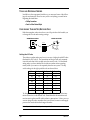
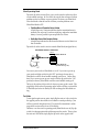
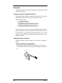
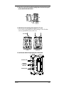
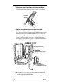
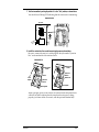
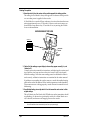
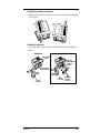
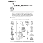
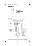
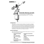
SENSORLINK™
INSTALLATION MANUAL
The SensorLink Transmitter (#7610) and SensorLink Receiver (#7611) are
designed to work with Davis Instruments’ Weather Monitor II® and the
Weather Wizard III® to enable wireless transmission of data between the sensors and console up to 400 feet (120 m). The SensorLink Transmitter/Receiver
pair takes the place of the junction box and cable that would normally connect
the outdoor sensors to the display console. The outdoor sensors connect to the
transmitter while the display console connects to the receiver.
One transmitter can send data to any number of Monitor II or Wizard III consoles, providing the console contains an receiver. The transmitter/receiver
communicate on one of 8 different ID codes set by the user. This allows multiple systems to coexist in the same geographical area.
Note: SensorLink operates on a low power frequency that does not require an FCC license.
C OMPONENTS
The SensorLink package includes the following. Please make sure you have
everything you need before beginning.
TRANSMITTER COMPONENTS
RECEIVER COMPONENT
#6 x 1" (25 mm long)
Self-Threading Screws
3 Volt
Lithium
Transmitter
Battery
Transmitter
Cable Ties
Receiver
Adhesive Pads
(not used)
Power Adapter
Product # 7610 & 7611
T OOLS
AND
M ATERIALS N EEDED
In addition to the components listed above, you may need some of the following tools and materials. Please be sure you have everything you need before
beginning the installation.
✦ Phillips Screwdriver
✦ Pencil or Other Pointed Object
C ONFIGURING T RANSMITTER /R ECEIVER P AIR
Both the transmitter and receiver have a set of dip switches which enable you
to change the ID code and warnings settings.
TRANSMITTER DIP SWITCHES
S1
RECEIVER DIP SWITCHES
ON
UNIT ID
1 2 3 4
ON
1 2 3 4
Setting the ID Code
The wireless weather station may be set to use any of eight selectable ID codes
(the default is ID Code #1). The transmitter and receiver will only communicate with each other if they are both set to the same ID code. Use the default
setting unless you have another Davis wireless weather station operating
nearby which you want to work separately from the new system. The dip
switch settings for the eight possible codes are shown below.
ID CODE
DIP SWITCH 1
DIP SWITCH 2
DIP SWITCH 3
#1(default)
#2
#3
#4
#5
#6
#7
#8
off
off
off
off
ON
ON
ON
ON
off
off
ON
ON
off
off
ON
ON
off
ON
off
ON
off
ON
off
ON
To change to another ID, toggle dip switches 1, 2, and/or 3 on both the transmitter and receiver to the desired code. Remember that the transmitter and
receiver must use the same ID code in order to communicate. If, later, you ever
want to change ID codes, remember that you will need to remove and reapply
power to the console before the changes take effect.
Note: Dip switch #4 is used for testing and warnings, not for ID codes.
Page 2
SensorLink™
Silent Operating Mode
Dip switch #4 on the receiver allows you to set the console to either stay silent
or emit audible warnings. In Silent Mode, the console does not beep to indicate
problems such as low battery or poor reception. The factory sets Silent Mode
off as the default so that the console will warn you when problems occur.
When Silent Mode is OFF:
✦ Triple Beep Warns of Transmitter Battery Problem
A triple beep every 10 minutes indicates that the transmitter battery is
extremely low on power. If you hear a triple beep, replace the transmitter
battery as soon as possible to prevent possible loss of data.
✦ Double Beep Warns of Data Reception Problem
A double beep indicates that the SensorLink has not received data for at
least 30 minutes.
Dip switch #4 on the console’s receiver controls Silent Mode (see figure below).
RECEIVER DEFAULT SETTINGS
UNIT ID
SILENT MODE ON
ON
1 2 3 4
SILENT MODE OFF
(Audible Warnings ON)
You can set your console to Silent Mode on or off. If you were to power up
your console with dip switch #4 in the “OFF” position (as shown above),
Silent Mode would be off and audible warnings would be on. On the other
hand, if you were to power up your console with the dip switch in the “ON”
position (not shown), Silent Mode would be on and audible warnings off.
The key is the position of dip switch #4 when you power up the console. Flipping the dip switch without repowering up the console will take you in and out
of Test Mode (see below for details), but will not change the Silent Mode setting.
Test Mode
To test signal reception at any point, simply flip the receiver’s dip switch #4 to
the opposite position from where it was when the console powered up. (You
will hear a periodic beep about every 2.5 seconds if the transmitter is within
range of the receiver and is also set to Test Mode.)
Therefore, to set the console’s operating mode (Silent Mode on or off), flip dip
switch #4 to the appropriate side and then repower the console. Then, to place
the receiver in Test Mode, simply flip the dip switch to the opposite side.
Configuring Transmitter/Receiver Pair
Page 3
I NSTALLATION
The instructions below will take you through the process required to install the
transmitter and receiver.
Choosing a Location for Transmitter and Receiver
The range of the radio transmission depends on several factors. Try to position
the transmitter and the receiver as close as possible for best results.
Typical maximum ranges:
✦ Line of Sight: 400 feet (120 m)
✦ Through Walls and Ceilings: 100 to 200 feet (30 to 60 m)
✦ Through Trees and Foliage: 100 to 200 feet (30 to 60 m)
As you position your console, be aware of possible interference from cordless
phones and other items. To prevent interference, maintain a distance of 10 feet
between the console and the cordless phone (handset and base). Also, for best
reception, avoid positioning the console near large metallic surfaces (e.g., most
refrigerator surfaces).
Installing Transmitter and Receiver
Install the transmitter in an attic or garage, or in one of Davis’s weatherproof
shelters.
1. Remove the cables from your existing junction box.
We recommend that you label the end of each cable as you disconnect it.
This will help you identify the cables when attaching them to the transmitter.
Page 4
SensorLink™
2. Remove the cover from the transmitter by pushing down on the tabs at the top until
you can remove the tabs from the slots.
B
A
Base
Cover
3. Attach the base to the mounting surface using the #6 x 1” screws.
Use two screws (as pictured below) when attaching to a stud. Use three
screws (as pictured below) in any other case.
#6 x 1" Screws
Use two screws if attaching
to a stud.
Use three screws if attaching
anywhere else.
4. Insert the sensor cables in the appropriate jacks, as shown below.
RAIN
Rain Collector Cable
Temperature
or Temp/Humidity
Sensor Cable
TEMP
WIND
Anemometer Cable
Installation
Page 5
5. Gather the sensor cables and secure them to the cable tie lug using a cable tie.
When tightening the cable tie, make sure the cables are on top of the lug.
When tightening
cable tie, make sure
cables are on top
of lug.
Cable Tie Lug
Cable Tie
6. Apply power to the transmitter using one of the options indicated below.
If you have a solar-powered system, connect the gel cell battery.
If you have a non-solar-powered system, decide whether you want to install
the power adapter OR the lithium battery (the two will NOT work in tandem or as backup). Davis recommends the battery to ensure power during
storms. If used as the primary power source, one fresh lithium battery
should provide about six months of service. Use two fresh lithium batteries
to double life (second is not provided).
SensorLink
Transmitter
2nd Lithium Battery (optional, not provided)
Lithium Battery
* Provided with non-solar systems
* RECOMMENDED - reliable power during storms
Gel Cell Battery
Power
Plug
* Provided with solar systems
* Rechargeable
* Recommended for solar-powered stations
* Reliable power during storms
Power Adapter
* Provided with non-solar systems
* NOT RECOMMENDED for use during storms power outages will disrupt data collection
Note: This illustration (as well as the following one) shows the transmitter mounted inside a Davis
Multi-Purpose Shelter (#7728). The Multi-Purpose Shelter is not required, but the transmitter
does need to be mounted in weatherproof location.
Page 6
SensorLink™
7. Test the transmitter by setting dip switch #4 to the “Test” position, as shown below.
You should see a flashing LED indicating that the sensor unit is transmitting.
TRANSMITTER TEST
Dip Switches
UNIT ID
TEST
S1
ON
1 2 3 4
RUN
Indicator
LED
SensorLink
Transmitter
8. Install the receiver into the console base and apply power as shown below.
Be sure to connect the receiver’s cable plug into the jack marked “Junction
Box” on the underside of the station console.
STANDARD SETUP
WEATHERLINK SETUP
Weather Station
Console
Weather Station
Console
To
Power
Adapter
Antenna
SensorLink
Receiver
Mounting Base
SensorLink
Receiver
To
Power
Adapter
WeatherLink
Mounting Base
When you apply power to the console, the console should beep three times
within 20 seconds to indicate that the console and receiver are working
properly (or 4 times within 30 seconds, with the optional WeatherLink).
Installation
Page 7
Testing Reception
1. Move dip switch #4 on the receiver to the position opposite its starting position.
The setting for Test Mode is always the opposite of wherever the dip switch
was set when power is applied to the console.
In Test Mode, the console will beep whenever it receives data from the transmitter (approximately every 2.5 seconds). If the two units are in range you
should hear a beep about every 2.5 seconds. If not, try moving the console
closer to the transmitter.
RECEIVER DEFAULT TEST MODE
UNIT ID
ON
Antenna
1 2 3 4
Dip Switches
SensorLink
Receiver
To Power
Adapter
2. Check all of the readings on your display to be sure they appear normally (i.e., not
“dashed out”).
Consult your station manual for instructions on displaying the various readings. Spin the wind cups and move the wind vane to verify wind speed/
direction readings. Note that some readings must be calibrated in order to
read correctly; calibration instructions are contained in the station manual.
If problems occur reading the outdoor sensors, consult the troubleshooting
guide at the end of this manual. If the inside temperature, inside humidity,
or barometer are not working properly, consult the station manual for troubleshooting.
3. Once finished testing, return dip switch #4 on the transmitter and receiver to their
original settings.
This will deactivate Test Mode; the LED Indicator on the transmitter should
stop flashing. On the receiver, position dip switch #4 to Silent Mode on or
off, as desired, and remove and reapply power to the console.
Note: Leaving the transmitter in Test Mode will cause the LED indicator to flash unnecessarily and
thus drain additional and nonessential power from your power supply.
Page 8
SensorLink™
4. Reattach the transmitter cover to the base.
Make sure the tabs on top of the cover snap back into their slots, locking the
cover in place.
A
B
5. Reattach the console base.
The closed console, with and without optional WeatherLink, is displayed
below.
STANDARD SETUP
WEATHERLINK SETUP
Weather Station
Console
WeatherLink
(inside Console Base)
SensorLink
Receiver
SensorLink Receiver
(inside Console Base)
Power
Adapter
110 VAC
Power Outlet
Installation
Power
Adapter
110 VAC
Power Outlet
WeatherLink
Connection
to Computer
Page 9
T ROUBLESHOOTING
While the Wireless Weather Station is designed to provide years of trouble-free
operation, occasional problems may arise. If you experience a problem, please
check the troubleshooters listed below before calling the factory. If you still are
unable to solve the problem, call the factory at (510) 732-7814 for assistance.
Please do not return your unit for repair without prior authorization.
✦ Console is receiving erratic data
Enable the Test Mode on the transmitter. If two beeps or more are heard in
a 2.5-second interval, then another Davis wireless system may be operating
nearby on the same ID, or a cordless phone may be operating within 10 feet
of the receiver. Either try changing to a different ID code on both the
receiver and the transmitter, or try moving the phone. Reapply power to
the console to activate the new ID code.
✦ Console is not receiving any data
The transmitter and the receiver may be too far apart, or something in their
path may be interfering, such as foliage, furnishings or cordless phones.
Enable Test Mode on the transmitter to see if it is receiving data. Try moving the receiver closer to the transmitter or vice versa; or eliminating possible path interferences.
✦ Console is emitting beeps
If you hear single beeps, flip dip switch #4 to turn off Test Mode in both the
transmitter and receiver.
If you hear a double beep, the SensorLink Receiver in the console is not
receiving data. This occurs when the receiver has not received data for 30
minutes. Try moving the receiver closer to the transmitter or vice versa; or
eliminating possible path interferences.
If you hear a triple beep, the transmitter is extremely low on power—replace
battery immediately.
✦ Data from the optional WeatherLink program shows temperature, humidity, or wind
values that were constant over some period
The SensorLink Receiver in the console did not receive new data during
this period and passed the last good data to the WeatherLink. Try moving
the receiver closer to the transmitter or vice versa; or eliminating possible
path interferences.
✦Battery(ies) are not lasting the expected 6 months (for 1 battery) or 1 year (for 2 bat-
teries)
Make sure dip switch #4 in the transmitter is set to OFF to prevent the LED
from flashing unnecessarily when not testing. If you are using two batteries, also make sure that both are fresh when installed.
Page 10
SensorLink™
S PECIFICATIONS
SensorLink Receiver
Receive frequency: 916.5 MHz
ID codes: 8 user-selectable
Temperature range: 0 to 60 °C
Update interval
Wind speed: 2.5 seconds
Wind Direction: 2.5 seconds
Outside Temperature: 16 seconds
Outside Humidity: 1 minute
Rain: 10 seconds (rain counts are saved in the transmitter until successfully
received by the console)
SensorLink Transmitter
Transmit frequency: 916.5 MHz
ID codes: 8 user-selectable
License: Low power (less than 1 mW), no license required
Sensor connections: Telephone modular for Anemometer, Temp/Hum Sensor,
and Rain Collector
Temperature range: -40 to 60 °C
Power Input Options
Battery power: CR-123 3- volt lithium or equal; one or two cells
AC power adapter: Davis adapter or equal (5 to 10 VDC output @ 1mA)
Solar Power Kit: Davis solar charger (Optional, product #7709. Offers the
added capability of replacing current power with a rechargeable solar
power supply.)
Specifications
Page 11
FCC P ART 15 C LASS B R EGISTRATION W ARNING
This equipment has been tested and found to comply with the limits for a class
B digital device, pursuant to Part 15 of the FCC Rules. These limits are
designed to provide reasonable protection against harmful interference in a
residential installation. This equipment generates, uses and can radiate radio
frequency energy and, if not installed and used in accordance with the instructions, may cause harmful interference to radio communications. However,
there is no guarantee that interference will not occur in a particular installation.
If this equipment does cause harmful interference to radio or television reception, which can be determined by turning the equipment off and on, the user is
encouraged to try to correct the interference by one or more of the following
measures:
✦ Reorient or relocate the receiving antenna.
✦ Increase the separation between the equipment and receiver.
✦ Connect the equipment into an outlet on a circuit different from that to which the
receiver is connected.
✦ Consult the dealer or an experienced radio/TV technician for help.
Shielded cables and I/O cords must be used for this equipment to comply with
the relevant FCC regulations. Changes or modifications not expressly
approved in writing by Davis Instruments may void the user's authority to
operate this equipment.
Product Numbers: 7610 & 7611
Davis Instruments Part Number: 7395-301
SensorLink™ Installation Manual
Rev. E Manual (10/15/99)
Controlled Online: Weather Manuals:Accessories:SensorLink
This product complies with the essential protection requirements of the EC EMC Directive 89/336/EC.
Weather Monitor II, Weather Wizard III, and WeatherLink are registered trademarks of Davis Instruments
Corp. © Davis Instruments Corp. 1998. All rights reserved.
3465 Diablo Avenue, Hayward, CA 94545-2778
510-732-9229 • Fax: 510-732-9118
E-mail: [email protected] • www.davisnet.com