1
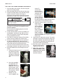
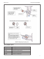
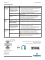
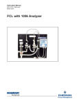
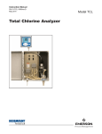
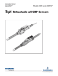
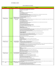
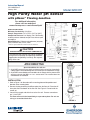
Instruction Manual
51A-3200HP/rev.F
January 2011
Model 3200 HP
High Purity Water pH Sensor
with pHaser Flowing Junction
TM
For additional information,
please visit our website at
www.emersonprocess.com/raihome/liquid/
inch
mm
SPECIFICATIONS
Minimum Conductivity: 0.4 µS/cm
Sample Temperature: 0°C to 70°C (32°F to 160°F)
Sample Inlet Pressure: 5 to 10 psig (134-170 kPa abs);
no back pressure allowed; sample must drain to open
atmosphere
Wetted Materials: Silicone, polycarbonate/ polyester,
glass, stainless steel, PVDF, Viton1
1. Viton is a registered trademark of DuPont Performance Elastomers.
CAUTION
SENSOR/PROCESS APPLICATION COMPATIBILITY
The wetted sensor materials may not be compatible
with process composition and operating conditions.
Application compatibility is entirely the responsibility of the user.
FIGURE 1
ATEX DIRECTIVE
Flow cell nut
Special Conditions for safe use
1. All pH/ORP sensors have a plastic enclosure which must only be cleaned with
a damp cloth to avoid the danger due to a build up of an electrostatic charge.
2. All pH/ORP sensor Models are intended to be in contact with the process fluid
and may not meet the 500V r.m.s. a.c. test to earth. This must be taken into
consideration at installation.
PN 3200HP
pH sensor
INSTALLATION
1. Refer to Figure 1 for dimensions of the mounting plate and the positions and
diameter of the mounting holes.
2. Remove the bag containing the diffuser plate from the flow cell. Place the diffuser plate flat in the bottom of the flow cell. See Figure 2. Do not install the
sensor yet.
3. Connect the sample and drain lines to the flow cell. Process connections
are ¼ inch FNPT.
The flow cell must drain immediately to open atmosphere. Do not use
a long or convoluted drain line.
PN 34083-00
Diffuser
Flow cell
FIGURE 2
MODEL 3200 HP
INSTALLATION
PUTTING THE 3200HP SENSOR IN SERVICE
1. Wire the cable to the analyzer. See the wiring diagrams in the wiring section.
2. Start the sample flow to fill the flow cell with water.
3. Unscrew the clear plastic nut on the flow cell and
slip the nut over the sensor. See Figure 2.
Remove the vinyl cap from the end of the sensor
and place the sensor in the water in the flow cell.
CAUTION
WARNING
The solution in the protective cap may cause
skin or eye irritation.
4.
5.
6.
7.
8.
Keep the capillary disc wet. See Figure 7. If the
disc dries out, it cannot be rehydrated, and it
must be replaced.
Do not remove the shipping plug from the tube
connected to the sensor.
Lift the reservoir bottle out of the clip holding it to
the backplate. Unscrew the cap and lay it on its
side in a clean place. Do not remove the protective cap attached to the filter.
Pour 500 mL of reference solution (PN 9210391)
into the reservoir. Replace the reservoir cap.
Remove the shipping plugs from the reservoir filter and the electrolyte tube. Connect the electrolyte tube to the filter by pressing the luer fitting
on the tube onto the luer fitting on the filter.
Invert the reservoir and slide it back into the clip.
A few drops of solution may drip out of the air vent.
Bleed air bubbles from the electrolyte tube and
sensor.
a. Loosen the bleed screw until it is engaged by
only about one thread.
Watch for bubbles flowing down the electrolyte
tube and out the bleed
port.
b. Once the last bubble
has appeared at the
bleed port allow an
additional 2 mL of solution to escape. Use a
paper towel to soak up
the electrolyte. Tighten
the bleed screw.
c. Bubbles may still
remain trapped in the
2
FIGURE 3
FIGURE 4
sensor. To
remove them,
take the sensor
out of the flow cell
and hold it with
the end of the
sensor slightly tilted above horizonFIGURE 5
tal. Keep the capillary disc facing up. Loosen the bleed screw
and let about 2 mL of solution escape.
d. Rotate the sensor slightly in the direction
shown by the
arrow in Figure 6
until the capillary
disc is about 60°
from vertical.
Watch for bubbles
leaving the port.
Bleed an additionFIGURE 6
al 2 mL of solution
after the last bubble has escaped. Tighten the
bleed screw.
9. Connect the VP cable to the sensor. The sensor
connector is keyed to ensure proper mating with
the cable receptacle. Once the key has slid into
the mating slot, hand tighten the connection by
turning the knurled ring clockwise.
10. Place the sensor in the flow cell. Be sure the capillary disc faces forward.
Tighten the flow cell nut.
11. Adjust the sample flow
Capillary
until it is between 1 and
Disc
3 gph (60 to 180 mL/min).
For best results flow
should be constant.
FIGURE 7
MODEL 3200 HP
WIRING
WIRING
The 3200HP sensor is available with Variopol (VP)
quick disconnect cable only. Although earlier versions
of the sensor were supplied with a VP6 cable, current
versions use a VP8 cable. The wiring diagrams in the
manual are for VP8 cable only. If you have a VP6
cable, refer to the wiring diagrams on our website,
www.raihome.com.
The table below gives part numbers for VP6 and VP8
cable:
Cable length
VP6
VP8
10 ft. (3.0 m)
20 ft. (6.1 m)
30 ft. (9.1 m)
23645-10
23645-11
23645-12
24281-06
24281-07
24281-08
If the part number is missing or not visible, identify the
cable by disconnecting it from the sensor and counting the number of gold contacts on the cable receptacle (not on the sensor). VP6 cable has six contacts;
VP8 has eight contacts.
Do not connect the blue wire or the clear inner drain wire.
Tape off each wire separately or cap with a wire nut to
prevent spurious connections. Use a wire jumper to connect
the solution ground terminal to the reference terminal.
Do not connect the blue wire or the clear inner drain wire.
Tape off each wire separately or cap with a wire nut to
prevent spurious connections. Use a wire jumper to connect
the solution ground terminal to the reference terminal.
FIGURE 8 1056 Wiring
FIGURE 9 54e Wiring
3
MODEL 3200 HP
Do not connect the blue wire or the clear inner drain wire.
Tape off each wire separately or cap with a wire nut to prevent spurious connections. Use a wire jumper to connect the
solution ground terminal to the reference terminal.
FIGURE 10 Xmt-P (panel mount) VP Wiring
Do not connect the blue wire or the clear inner drain wire.
Tape off each wire separately or cap with a wire nut to prevent spurious connections. Use a wire jumper to connect the
solution ground terminal to the reference terminal.
FIGURE 12 5081-P VP Wiring
4
WIRING
Do not connect the blue wire or the clear inner drain wire.
Tape off each wire separately or cap with a wire nut to
prevent spurious connections. Use a wire jumper to connect
the solution ground terminal to the reference terminal.
FIGURE 11 Xmt-P (wall/pipe mount) VP Wiring
Do not connect the blue wire or the clear inner drain wire.
Tape off each wire separately or cap with a wire nut to
prevent spurious connections. Use a wire jumper to connect
the solution ground terminal to the reference terminal.
FIGURE 13 6081-P VP Wiring
MODEL 3200 HP
CALIBRATION
1. Select two stable buffer solutions. Ideally, the calibration buffers should bracket the expected pH of
the sample and be at least two pH units apart.
Use the ring at the bottom of the back plate to
hold the beaker containing the buffer.
2. Most pH meters offer automatic buffer recognition.
Automatic buffer recognition means the instrument
automatically calibrates using the correct pH for
the buffer temperature. (The pH of a buffer, particularly one with alkaline pH, changes as the temperature changes.) If the meter does not have
automatic buffer recognition, refer to the label on
the buffer bottle for a table of pH versus temperature.
3. Remove the sensor from the flow cell and rinse it
with deionized water. Immerse it in the first buffer.
Be sure the capillary disc is completely submerged.
Gently swirl the sensor in the buffer for a few
seconds. Allow the sensor and buffer to reach the
same temperature. Once pH readings are stable,
start the calibration. Follow the procedure in the
analyzer instruction manual.
4. After the sensor has been calibrated in the first
buffer, remove and rinse it with deionized water.
Place the sensor in the second buffer and complete
the calibration.
5. After the calibration is complete, check the slope
and intercept of the sensor. The slope should be
between 56 and 60 mV/pH and the offset should
be between -20 and 20 mV.
CALIBRATION / ELECTROLYTE REPLACEMENT
REPLACING THE ELECTROLYTE
SOLUTION (PN 9210391)
The reference electrolyte solution should last two to
three months. To replace the electrolyte solution:
1. Remove the reservoir bottle from the clip on the
back plate. Turn the bottle upright.
2. Unscrew the cap without disconnecting the filter or
electrolyte tube. To avoid twisting the electrolyte
tube, turn the bottle, not the cap. To keep the
cap and air inlet tube clean, hang the cap from
the reservoir clip using the electrolyte tube.
3. Discard any remaining fill solution.
4. Pour 500 mL of new reference fill solution (PN
9210391) into the reservoir.
5. Replace the cap. Remember to turn the bottle, not
the cap.
6. Invert the bottle and reattach it to the clip.
7. Bleed air bubbles from the tube and sensor. Refer
to step 8 in the “Putting the Sensor in Service”
section.
5
MODEL 3200 HP
REPLACING THE CAPILLARY DISC
(PN 34142-00)
The reference capillary is protected by two filters, one
on the inside of the disc and the other on the sample
side. During normal operation, suspended solids in
the sample coat the filter and hinder flow through the
capillary. Occasionally, bacterial or fungal growth in the
electrolyte solution will coat the inside filter. Eventually,
as the coating builds up, the electrolyte flow becomes
too low and the capillary disc must be replaced. The
typical symptom of a blocked capillary disc is abnormally low use of electrolyte (500 mL of electrolyte
should last no more than two months) or pH readings
significantly lower (0.5 pH) than expected.
The capillary disc will also become blocked if the filters
are allowed to dry out. Dried out filters cannot be rehydrated. They must be replaced.
To replace a capillary disc:
1. Lift the electrolyte reservoir out of the clip on the
back plate. Turn the bottle upright and disconnect
the electrolyte tube from the filter. Place the shipping plug on the filter.
2. Disconnect the VP cable from the sensor and
remove the sensor from the flow cell.
3. Hold the sensor in a horizontal position with the
capillary disc pointing up. Use a small screwdriver
to gently pry the disc and O-ring out of the gland.
Take care not to scratch the gland. See Figure 14.
6
CAPILLARY DISC REPLACEMENT
4. Remove the replacement capillary disc and O-ring
from the container. Be careful not to touch the
white filter membrane portion of the disc with
your fingers. Wear latex gloves if necessary.
5. Place the sealing O-ring on the back side of the
replacement capillary disc. See Figure 14. Put the
disc aside in a clean place. Keep the capillary
disc wet. If the disc dries out it cannot be rehydrated and must be replaced.
6. Fill the reference junction port with electrolyte
solution or deionized water until the level slightly
overflows the port.
7. Place the new capillary disc with the sealing
O-ring facing down in the port. Use your finger
tips – do not let your bare fingers touch the
white filter membrane – to push the capillary
disc straight into the port. See Figure 14. If inserting the disc is difficult, place the open end of a
clean ¼ inch compression fitting nut on the transparent portion of the disc and push the disc into
place by gently press straight down on the nut.
8. Reconnect the VP cable to the sensor. Place the
sensor back in the flow cell and reattach the electrolyte tube to the reservoir filter.
9. Slide the reservoir back into the clip.
10. Bleed air bubbles from the tube and sensor. Refer
to step 8 in the Putting the Sensor in Service section.
MODEL 3200 HP
CAPILLARY DISC REPLACEMENT
FIGURE 14 Replacing the capillary disc.
REPLACEMENT PARTS
Part number
Description
34132-00
Flowing junction reference capillary disc and O-ring
9160590
Cartridge filter for reference electrolyte solution
9210391
Reference fill solution, 500 mL
3200HP
Replacement 3200HP pH sensor
9601025
Air bleed screw
9913804
Washer for air bleed screw
7
MODEL 3200 HP
TROUBLESHOOTING
TROUBLESHOOTING
Problem
Cause
Solution
pH reading
is in error
Electrolyte flow is too low –
bubbles are blocking flow
or the inside membrane on
the capillary disc is fouled
with biological growth.
1. Remove air bubbles. Follow the procedure in step 8 of the
Putting the Sensor in Service section.
2. Discard the fill solution in the reservoir and sensor. Rinse
the reservoir and sensor with fresh fill solution. Replace
with fresh solution. Replace reservoir filter.
Capillary is plugged.
Replace capillary.
Sensor was not properly
calibrated.
Check buffers for freshness and replace if necessary. Pay
particular attention to alkaline buffers, which can become
contaminated with atmospheric carbon dioxide. Review
calibration procedure and repeat calibration.
Sample flow is too high.
Adjust sample flow to between 1 and 3 gph (60 to 180 mL/min).
Sensor is not properly
oriented in flow cell.
Orient sensor so that capillary disc faces the front.
Electrolyte flow is too low –
bubbles are blocking flow
or the inside membrane on
the capillary disc is fouled
with biological growth.
1. Remove air bubbles. Follow the procedure in step 8 of the
Putting the Sensor in Service section.
2. Discard the fill solution in the reservoir and sensor. Rinse
the reservoir and sensor with fresh fill solution. Replace
with fresh solution. Replace reservoir filter.
Sensor is dirty.
Clean the outside capillary filter by rinsing with deionized
water. Clean the pH glass bulb by rinsing with dilute
hydrochloric acid. Recalibrate the sensor after cleaning.
Unstable sample.
Fluctuations in sample flow can cause slight changes in pH
reading. Keep sample flow constant. Be sure the sample
drains immediately to open atmosphere.
Noisy
reading
pH readings
drift
The right people,
the right answers,
right now.
ON-LINE ORDERING NOW AVAILABLE ON OUR WEB SITE
http://www.raihome.com
Specifications subject to change without notice.
8
Credit Cards for U.S. Purchases Only.
Emerson Process Management
2400 Barranca Parkway
Irvine, CA 92606 USA
Tel: (949) 757-8500
Fax: (949) 474-7250
http://www.raihome.com
© Rosemount Analytical Inc. 2011