1
Programming Manual
PL12-1300
12/00
Cleco
Electric Tool Control
TME-100 Series
Reference Document: PL12-1400 Parts Manual
For additional product information visit our website at http://www.coopertools.com
A M
E R I
C A
S
CooperTools
P.O. Box 1410
Lexington, South Carolina 29071-1410
E
U R O P E
Cooper Power Tools GmbH & Co.
Postfach 30
D-73461 Westhausen
Electric Tool Control TME-100 Series
Cleco
Disclaimer:
The information and data in this document has been prepared to the best of our ability.
Nonetheless, differences between the information and the actual product cannot be
excluded with absolute certainty. Cooper Tools does not assume any liability for consequential errors and damages. We likewise do not assume liability for damages resulting
from defective circuitry inside the devices supplied. Cooper Tools reserves the right, to
ammend, supplement or improve this document or the product without serving prior
notice.
Without the express approval of Cooper Tools this document must not be reproduced in
its entirity or in part by any means; it must not be converted to any type of natural or
machine readable language or be saved on data storage media of electronic, mechanic,
optical or other type.
2
PL12-1300 12/00
en00d141.fm, 30.01.2001
Electric Tool Control TME-100 Series
Cleco
Contents
Page
1
Getting Started
5
1.1
1.2
1.3
1.4
1.4.1
1.4.2
1.4.3
1.4.4
1.5
1.5.1
1.6
Safe Work Practices Symbol ................................................................
Checking Your Unit...............................................................................
Software ...............................................................................................
Installing Unit ........................................................................................
General.................................................................................................
Mounting...............................................................................................
Location Considerations .......................................................................
Source Power .......................................................................................
Connecting Unit ....................................................................................
General.................................................................................................
Energizing Unit .....................................................................................
5
5
5
5
5
6
6
6
6
6
7
Attachment A.1
9
2
Controller Specifications
2.1
2.2
2.2.1
2.2.2
2.2.3
2.2.4
2.2.5
2.2.6
2.2.7
2.2.8
Understanding the Keypad .................................................................. 11
Specifications ..................................................................................... 12
Enclosure ........................................................................................... 12
Display................................................................................................ 12
Keypad Overlay .................................................................................. 13
Indicators ............................................................................................ 13
CPU with PC/104................................................................................ 13
Internal AC Input Power ..................................................................... 14
Inernal DC Power ............................................................................... 14
Input / Output Connectors .................................................................. 14
3
Programming
19
3.1
3.1.1
3.1.2
3.1.3
3.2
3.2.1
3.2.2
3.2.3
3.2.4
3.3
3.3.1
3.3.2
3.3.3
Navigator Menu ..................................................................................
Basic Navigation Instructions .............................................................
Password Function .............................................................................
Navigator Menu ..................................................................................
Basic Application Builder ....................................................................
Basic Parameters for Torque Control / Angle Monitor ........................
Basic Parameters for Angle Control / Torque Monitor ........................
Basic Application Builder Parameters ................................................
Advanced Parameter Default Values..................................................
Standard Application Builder ..............................................................
Standard Application Builder / View Stages........................................
Standard Application Builder / Select Sequence ................................
Standard Application Builder / Parameters.........................................
19
19
19
20
21
22
22
23
23
24
24
25
27
end14IVZ.fm, 30.01.2001
PL12-1300 12/00
11
3
Electric Tool Control TME-100 Series
4
Cleco
3.3.4
3.3.5
3.3.6
3.3.7
3.3.8
3.4
3.5
3.6
3.6.1
3.6.2
3.7
3.8
3.8.1
3.8.2
3.9
3.9.1
3.9.2
3.10
3.10.1
3.10.2
3.10.3
3.10.4
3.10.5
3.10.6
3.10.7
3.10.8
3.10.9
3.11
3.11.1
3.12
3.12.1
3.12.2
3.12.3
3.12.4
Standard Application Builder / Advanced Parameters ........................
Advanced Application Builder / Application Matrix ..............................
Advanced Application Builder / Inputs.................................................
Advanced Application Builder / Outputs..............................................
Advanced / System Settings ...............................................................
RUN Screen ........................................................................................
Oscilloscope........................................................................................
Communication ...................................................................................
Communications / Printer....................................................................
Communications / Serial Data Transmission ......................................
Tool Setup ...........................................................................................
Tool Library..........................................................................................
Tool Library..........................................................................................
Tool Library / Custom ..........................................................................
Statistics ..............................................................................................
Statistics / Summary............................................................................
Statistics / Chronological History.........................................................
Diagnostics..........................................................................................
Inputs / Outputs ...................................................................................
Tool / Calibration .................................................................................
Tool / Voltages.....................................................................................
Tool / Angle Encoder ...........................................................................
Tool / TQ Measurement.......................................................................
Tool / Speed ........................................................................................
Arcnet / Map........................................................................................
Arcnet / Statistic ..................................................................................
Serial ...................................................................................................
Utilities.................................................................................................
Utilities / Update Software...................................................................
Administration .....................................................................................
Administration / Load/Save .................................................................
Administration / Print ...........................................................................
Administration / Password...................................................................
Administration / Date & Time ..............................................................
31
32
33
34
36
36
37
38
38
39
40
41
41
42
43
43
43
44
44
45
46
47
48
48
49
50
52
53
53
54
54
55
55
56
4
Statistics
57
4.1
4.1.1
4.1.2
4.1.3
4.1.4
4.2
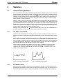
Understanding Statistics......................................................................
The Nature of Variation .......................................................................
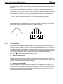
The Normal Curve...............................................................................
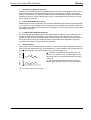
The Procedure ....................................................................................
System Improvement ..........................................................................
Statistic Symbols .................................................................................
57
57
57
58
62
63
5
Glossary
65
PL12-1300 12/00
end14IVZ.fm, 30.01.2001
Electric Tool Control TME-100 Series
Cleco
1
Getting Started
1.1
Safe Work Practices Symbol
!
CAUTION!
1.2
The signal word "Warning" identifies all notes on safe work practices in this operating
instruction, alerting to hazards for life and health of people. Observe these notes and proceed with special care in the cases described. Pass all safety instructions on to other
operators. In addition to the safety instructions in this operating instruction, the general
local safety and accident prevention rules must be observed.
The signal word "Caution!" identifies all portions of this operating instruction meriting
special attention to ensure that guidelines, rules, hints and the correct work procedures
are observed; and, to prevent damage to and destruction of the machine and/or parts.
Checking Your Unit
Take the time to ensure you have the required peripheral equipment and cables necessary to
setup and run your unit. If you do not have all the necessary items, contact your distributor.
Refer to “Attachment A.1” on page 9 for illustration of your unit.
1.3
Software
Your unit has been pre-loaded with version 1.0 software and requires no additional software to
begin your fastening process. If you are interfacing your unit with an external computer, interfacing software is required. Contact your distributor for the interfacing software.
1.4
Installing Unit
1.4.1
General
!
It is mandatory that national, state and local safety and wiring standards be followed during installation. These standards would take precedence over any information presented
in this section.
To avoid the hazard of electrical shock or burn, the following instructions must be
adhered to. Failure to follow these instructions may also cause damage to your unit and
void existing warranties.
CAUTION!
•
Do not energize the unit until all connections have been properly made.
•
Equipment must be properly grounded before applying power. Units energized by
cord and plug must be connected to an approved and properly grounded receptacle.
•
All units must be energized by an isolated line.
•
The unit door must always be closed and secured prior to energizing the unit.
•
Ensure the power switch is in the "off" position prior to connecting the power cord.
Though it is not mandatory, the following instructions are highly recommended for the
protected operation of your unit.
•
Use an isolation transformer and surge arrestor on the incoming isolated line.
•
Use oversized feeder lines to reduce electrical noise and voltage drop.
en01d141.fm, 30.01.2001
PL12-1300 12/00
5
Electric Tool Control TME-100 Series
1.4.2
Cleco
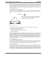
Mounting
Each unit is used primarily as a single tool process/controller/monitor installed in a work station
or work area. It may be wall mounted, table mounted, beam mounted, suspended overhead,
pedestal mounted or used without mounting. Always choose a stable location to avoid the possibility of unit damage and/or operator injury through hitting, falling, vibration or inconvenient
mounting. All cables attached to the unit should be located and secured in a manner to avoid
potential operator and passer-by injury. As with all electrical equipment, the unit will produce
some heat and should be located so that ambient air can freely circulate around the box.
Refer to Illustration Q of the parts manual, PL12-1400 for mounting hole dimensions.
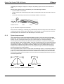
1.4.3
Location Considerations
Your unit should be located to allow access to the front panel and connectors. The unit should
be installed for unrestricted and comfortable viewing of the LCD & LED's by the operator. The
LCD menu screen, key pad and side door connectors must be readily accessible for the setup.
Dependent on the peripheral equipment purchased, the unit may be located in a remote position
but should still be accessible.
Attachment of accessories and tools should also be considered with the installation locations.
Items to be considered are:
1.4.4
•
Location of printer (10 ft. cable maximum for the parallel interface).
•
Attachment of a data collection unit, if desired.
•
Attachment of redundant master transducers (less than 50 ft. is desirable).
•
Attachment of remote annunciators, socket nest, or remote parameter select.
•
Attachment of the unit in a network to a computer.
•
Operation convenience/safety - keep cables off the floor or dangling in operator areas.
Source Power
Your unit, which is used as the process control and power supply for the Cleco DC electric tools,
requires a power line with 10 amp capacity at 220-240 Volts AC (50/60 Hz) for the TME-111-30.
The TME-111-15 requires a power line with 15 amp capacity at 110-130 Volts AC (50/60 Hz).
1.5
Connecting Unit
1.5.1
General
Connect all equipment to the correct input and output connectors. Refer to “Attachment A.1” on
page 9 for proper port locations.
!
6
To avoid the hazard of electrical shock or burn the following instructions must be
adhered to. Failure to follow these instructions may also cause damage to your unit and
void existing warranties.
•
Ensure the power switch is in the "off" position and that the box cover is properly
secured prior to connecting power cord.
•
Ensure equipment has been properly grounded before applying power.
PL12-1300 12/00
en01d141.fm, 30.01.2001
Electric Tool Control TME-100 Series
1.6
!
Cleco
Energizing Unit
To avoid the hazard of electrical shock or burn the following instructions must be
adhered to. Failure to follow these instructions may also cause damage to your unit and
void existing warranties.
Upon application of power, the unit will initiate a self test. The initialization takes approximately
45 seconds.
The introduction screen shown below will be displayed for approximately 10 seconds and then
the navigator menu will be displayed.
c00276de.bmp
Fig. 1-1: Introduction Screen
c00277en.bmp
Fig. 1-2: Navigator Menu
en01d141.fm, 30.01.2001
PL12-1300 12/00
7
Electric Tool Control TME-100 Series
Cleco
After the Navigator Menu is displayed, verify the Tool Memory by entering Tool Setup. If Tool
Memory is not active then select a tool using the Tool Library. Press the ship's wheel to return to
the Navigator Menu.
Once Tool Setup is complete the application needs to be programmed. To do this, go to Basic
Application Builder. From this screen torque, angle, and speed parameters must be entered for
the selected application. Press the ship's wheel to return to the Navigator Menu.
The controller is now ready to begin fastening cycles. The torque and angle data can be viewed
by pressing the Run Key. Tool and controller indicator lights will illuminate according to the
results.
8
PL12-1300 12/00
en01d141.fm, 30.01.2001
Electric Tool Control TME-100 Series
Cleco
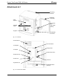
Attachment A.1
Mounting
Bracket
Sidedoor
Assembly
LCD
Display
Connector
Box
(see detail
below)
Indicator
Lights
Keypad
Double-Bit
Enclosure
Fig. 1-3: Controller
Power Switch
Tool Connector
I/O Outputs
Floppy Drive
I/O Inputs
Printer Power Out
Serial Ports (2)
Printer Port
Power In
Keyboard Port
Double-Bit Enclosure key
Fig. 1-4: Connector Box Detail
en01d141.fm, 30.01.2001
PL12-1300 12/00
9
Electric Tool Control TME-100 Series
10
Cleco
PL12-1300 12/00
en01d141.fm, 30.01.2001
Electric Tool Control TME-100 Series
Cleco
2
Controller Specifications
2.1
Understanding the Keypad
The following is a brief explanation of the keypad keys. You will need to become familiar with
these keys so you can smoothly program your unit.
Soft Keys (F1-F4)
- used to select functions based on the screen displayed.
ESC Key
- used at any time to return back one screen or exit the edit mode.
DEL Key
- used to delete a numerical value on the LCD screen.
Arrow Keys
- used to move the orange highlight around the screen.
ENTER Key
- used to accept an answer/value on the LCD screen.
Ships Wheel
- used at any time to return to the navigator menu.
Run
- used at any time to return to Run Screen.
Soft Keys
Ship´s Wheel
en02d141.fm, 30.01.2001
PL12-1300 12/00
11
Electric Tool Control TME-100 Series
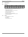
2.2
Specifications
2.2.1
Enclosure
Model
TME-111
Cleco
Weight*
Width
Height
Depth
lb
kg
in
mm
in
mm
in
mm
80
36.4
16.5
419.1
17.5
444.5
12.3
312.4
* Mounting plate adds weight of 7 lbs / 3.2 kg and depth of 1.62 in / 41.1 mm
2.2.2
12
•
Designed for NEMA 13/IP54 rating
•
Lockable front door for customer specific key requirements
•
Lockable 3-phase power switch
•
Side door for connector/cable protection
•
Removable Mounting Plate
•
Removable, fully operational internal chassis
•
Conductive front door gasket and lip to meet EMI regulations
•
Orange textured powder coat
Display
•
7.7 in Passive Matrix Color LCD Module
•
640 x 480 resolution
•
CCFT backlight
•
Contrast and Brightness control
PL12-1300 12/00
en02d141.fm, 30.01.2001
Electric Tool Control TME-100 Series
2.2.3
Cleco
Keypad Overlay
Key Definitions
Key
Description
0-9
Numbers 0-9
.
Decimal point
DEL
Delete
ESC
Escape
Navigator Menu
RUN
Run Screen
Up Arrow
Down Arrow
Left Arrow
Right Arrow
2.2.4
ENTER
Enter
Orange Border
4 Soft Keys
Indicators
5 Highly visible indicators
2.2.5
•
2 red groupings
•
1 green grouping
•
2 amber groupings
•
Each grouping contains 12 high intensity LED´s @ 30 mcd each
CPU with PC/104
Minimum Requirements
•
Pentium 133 Mhz
•
32 MB DRAM
•
16 MB DiskonChip
•
4 serial ports
•
1 parallel port
•
Ethernet 100-Base T
•
PC Keyboard input
•
PC/104 Bus
•
Floppy interface
•
LCD/Flat Panel controller
en02d141.fm, 30.01.2001
PL12-1300 12/00
13
Electric Tool Control TME-100 Series
Cleco
Arcnet PC/104 board
•
Arcnet communication
•
4 +24 V inputs
•
12 +24 V outputs
•
24-position keypad decoder
•
Battery-Backed SRAM, 1 MB
External I/O PC/104 board
2.2.6
2.2.7
2.2.8
14
•
8 optically isolated inputs
•
8 relay outputs
•
Switching levels to meet IEC-1131-2
Internal AC Input Power
•
Selectable 115 VAC @15 A or 230 VAC @ 10 A, +/-5% on all voltages
•
Internal fuse
•
Fault current circuit-breaker (10 mA)
•
Isolation Transformer 4.5 kVA peak, meets VDA 0570 norm
Inernal DC Power
•
Input: 85 VAC-264 VAC
•
Output: +5 VDC @ 5 A, +12 VDC @ 1 A, +24 VDC @ 3 A, +/-5% on all voltages
•
110 W capability without a fan
•
MTBF->20,000 hours
Input / Output Connectors
Tool Connector
Matrix MS83723R/2028N
Serial (2)
9-pin Male D-Shell
Parallel
25-pin Female D-Shell
Keyboard
Mini 6-DIN
Inputs (+24 V)
Phoenix MSTBV 2,5/12-GF-5,08 Order No. 1777170
Outputs
Phoenix ICV 2,5/12-GF-5,08 Order No. 1825792
Floppy
3.5in 1.44 MB
AC Power Input
Standard male receptacle
AC Power Output
Standard female receptacle
PL12-1300 12/00
en02d141.fm, 30.01.2001
Electric Tool Control TME-100 Series
Cleco
Tool
Pin #
Description
Value
1
+Excitation
+12 V +/- .05 V
2
-Excitation
0V
3
Drehmomentsignal
0 to +5 V
4
0 V Drehmomentsignal
0V
5
Tool Memory TXD -
-3 V to +3 V
6
Tool Memory TXD +
-3 V to +3 V
7
Tool Memory RXD -
-3 V to +3 V
8
Tool Memory RXD +
-3 V to +3 V
9
Resolver Carrier R1
7 VAC
10
Resolver Carrier R2
0 VAC
11
Resolver Cosine S1
7 VAC
12
Red LED
0 to +24 V
13
Signal GND
0V
14
Yellow LED
0 to +24 V
15
Motor PE
0V
16
Start Switch
0 to +24 V
17
Reverse Switch
0 to +24 V
18
+24V
+24 V
19
Motor Phase C
0 to 300 V
20
Transducer Calibration
0 to +5 V
21
Temperature Sensor +
0 to +5 V
22
Temperature Sensor -
0 to +5 V
23
Motor Phase B
0 to 300 V
24
Resolver Sine + S2
7 VAC
25
Resolver Cosine S3
0 VAC
26
Resolver Sine S4
0 VAC
27
Motor Phase A
0 to 300 V
28
Green LED
0 to +24 V
Housing
PE
0V
Serial
en02d141.fm, 30.01.2001
Pin #
Description
Value
1
DCD
-25 V to +25 V
2
RxD
-25 V to +25 V
3
TxD
-25 V to +25 V
4
DTR
-25 V to +25 V
5
GND
0V
6
DSR
-25 V to +25 V
7
RTS
-25 V to +25 V
PL12-1300 12/00
15
Electric Tool Control TME-100 Series
Cleco
Serial
8
CTS
-25 V to +25 V
9
RI
-25 V to +25 V
Parallel
Pin #
Description
Value
1
Strobe
0 to +5 V
2
Data 0
0 to +5 V
3
Data 1
0 to +5 V
4
Data 2
0 to +5 V
5
Data 3
0 to +5 V
6
Data 4
0 to +5 V
7
Data 5
0 to +5 V
8
Data 6
0 to +5 V
9
Data 7
0 to +5 V
10
Acknowledge
0 to +5 V
11
Busy
0 to +5 V
12
Paper Out
0 to +5 V
13
Select Out
0 to +5 V
14
Auto Feed
0 to +5 V
15
Error
0 to +5 V
16
Initialize
0 to +5 V
17
Select In
0 to +5 V
18
Gnd
0V
19
Gnd
0V
20
Gnd
0V
21
Gnd
0V
22
Gnd
0V
23
Gnd
0V
24
Gnd
0V
25
Gnd
0V
Keyboard
16
Pin #
Description
Value
1
Data
0 to +5 V
2
N/C
N/A
3
Gnd
0V
4
Power
0 to +5 V
5
Clock
0 to +5 V
PL12-1300 12/00
en02d141.fm, 30.01.2001
Electric Tool Control TME-100 Series
Cleco
Inputs
Pin #
Description
Value
1
+24 V (Output)
+24 VDC
2
Input 0
0 to +24 V
3
Input 1
0 to +24 V
4
Input 2
0 to +24 V
5
Input 3
0 to +24 V
6
Input 4
0 to +24 V
7
Input 5
0 to +24 V
8
Input 6
0 to +24 V
9
Input 7
0 to +24 V
10
Input Common (Input)
0V
11
Signal Gnd (Output)
0V
12
Spare
N/A
Outputs
en02d141.fm, 30.01.2001
Pin #
Description
Value
1
+24 V (Output)
+24 VDC
2
Output Common (Output)
0 to 30 V
3
Output 0
0 to 30 V
4
Output 1
0 to 30 V
5
Output 2
0 to 30 V
6
Output 3
0 to 30 V
7
Output 4
0 to 30 V
8
Output 5
0 to 30 V
9
Output 6
0 to 30 V
10
Output 7
0 to 30 V
11
Signal Gnd (Output)
0V
12
Spare
N/A
PL12-1300 12/00
17
Electric Tool Control TME-100 Series
18
Cleco
PL12-1300 12/00
en02d141.fm, 30.01.2001
Electric Tool Control TME-100 Series
3
Programming
3.1
Navigator Menu
Cleco
c00277en.bmp
Fig. 3-1: Navigator Menu
3.1.1
Basic Navigation Instructions
Each field in a screen is selectable with an orange highlight using the 4 arrow keys and Enter.
Upon entering a screen the top left most field is always highlighted. The Navigator key (ship's
wheel) will always return the user to the Navigator Menu. At the bottom of the screen 4 soft keys
are available. These functions will change from screen to screen. In some cases the screen
label will contain the (>>) character to indicate more functions are available when the key is
pressed.
To edit a textbox the user can use 0-9 or the DEL keys. To exit the edit mode the user can press
the arrow keys to move the highlight or press the ESC key. The ESC key will return the original
value.
In order to describe the soft key functions the left soft key is referred to as F1, center left soft key
F2, center right soft key F3 and right soft key F4. They are located in the orange display border.
F4 always functions as Help for that screen.
Applications are selectable 1-8.
Stages are selectable 1-6.
3.1.2
Password Function
If the user exits a section with programmable data (Basic, Standard, Advanced, Communications, Tool Setup) that has been changed, then the password entry dialog will be displayed. If no
password is activated, then only the confirm entry in the password dialog is displayed. Once the
password has been entered, it must be entered each time an appropriate screen is exited.
en03d141.fm, 30.01.2001
PL12-1300 12/00
19
Electric Tool Control TME-100 Series
3.1.3
Cleco
Navigator Menu
Basic Application Builder
Basic Application Builder allows the user to graphically select and program a two-stage rundown
for Torque Control/Angle Monitor (Sequence 11/Sequence 30) or Angle Control/Torque Monitor
(Sequence11/Sequence 50) for any of the 8 Applications. The user only enters Torque, Angle,
and Speed Setpoints in one screen. Other parameters such as timers, etc are automatically
defaulted to pre-determined values.
Standard Application Builder
Standard Application Builder allows the user to program up to a 6-stage rundown for any of the 8
Applications. Once the fastening sequences are selected for each stage, the associated Torque,
Angle, Speed, and Advanced parameters can be programmed.
Advanced Application Builder
Advanced Application Builder allows the user to View and Edit all 8 Application setups at once,
and perform I/O Mapping. The Application Matrix shows an overview of Application and Stage
programming by displaying the selected Fastening Sequence for each stage. Stages can be
copied from one to the other or programmed directly from the Parameter soft key. I/O Mapping
lets the user select from a list of functions and assign that function to a given input or output.
RUN Screen
The Run Screen button takes the user directly to the display for Torque, Angle, and Status Indicator Labels. The Oscilloscope function used for diagnosing torque traces is also located in the
Run Screen.
Communications
The Communications Setup allows the user to configure all communications for the Printer and
Serial Data Transmission. Appropriate communications settings for protocol, port, baud rate, etc
can be set in this screen.
Tool Setup
The Tool Setup displays the Tool Memory Data and allows the user to modify this information by
changing it directly or selecting from the Tool Library. The user can also create and save custom
tool setups under new model numbers.
Statistics
Chronological History and associated statistics are viewable from this screen. Data can be
erased and printed as well.
Diagnostics
The System Diagnostics contains screens to determine if the system is functioning properly.
There are diagnostics for I/O, Arcnet, Tool and Tightening Module, Serial Communications, and
Transducer Calibration.
Utilities
Utilities contains functions for upgrading or changing the system software. From the Utilities
screen the user can update the TME-100 application software from the floppy, install a new firmware version in the Tightening Module from the floppy, or set the application software language
(English, German, Spanish, Portuguese).
20
PL12-1300 12/00
en03d141.fm, 30.01.2001
Electric Tool Control TME-100 Series
Cleco
Administration
From the Administration screen the user can load, save and configure system information.
Administration functions include loading and saving the system parameters to a diskette, setting
date and time, setting password protection, and printing the system parameters.
3.2
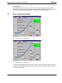
Basic Application Builder
c00278en.bmp
Fig. 3-2: Torque Control / Angle Monitor
c00279en.bmp
Fig. 3-3: Angle Control / Torque Monitor
The Basic Application Builder allows the user to select a typical two-stage rundown where the
first stage is a high speed rundown and the second stage is a lower speed rundown that controls
on either torque or angle.
en03d141.fm, 30.01.2001
PL12-1300 12/00
21
Electric Tool Control TME-100 Series
Cleco
Fastening Strategies Torque Control/Angle Monitoring (Sequence 11/Sequence 30) or Angle
Control/Torque Monitoring (Sequence 11/Sequence 50) are selectable from the dropdown listbox in the upper right hand corner of the screen. Once a Strategy is selected, the appropriate
Parameters will be displayed for programming.
3.2.1
3.2.2
Basic Parameters for Torque Control / Angle Monitor
•
Trigger Torque [Nm] - Torque to start collecting oscilloscope data.
•
Turnoff Torque Stage 1 [Nm] - Torque to change from stage 1 to stage 2.
•
Threshold Torque [Nm] - Torque to begin counting angle in stage 2.
•
Torque Low Limit [Nm] - Minimum acceptable torque.
•
Turnoff Torque Stage 2 [Nm] - Torque to turnoff the tool.
•
Torque High Limit [Nm] - Maximum acceptable torque.
•
Angle Low Limit [Deg] - Minimum acceptable angle.
•
Angle High Limit [Deg] - Maximum acceptable angle.
Basic Parameters for Angle Control / Torque Monitor
•
Turnoff Angle [Deg] - Angle to turnoff the tool.
•
The rest of the Parameters are the same as Torque Control/Angle Monitor except Turnoff
Torque Stage 2 is eliminated.
Below are the acceptable ranges for each Parameter and its default value. For initial programming, the Parameters automatically use the default values.
22
PL12-1300 12/00
en03d141.fm, 30.01.2001
Electric Tool Control TME-100 Series
3.2.3
Cleco
Basic Application Builder Parameters
Parameter Name
Range
Default
Fastening Strategy
Torque Control/Angle Monitor
Angle Control/Torque Monitor
Torque Control/Angle Monitor
Trigger Torque [Nm]
0 to Tool Max
0.0
Turnoff Torque Stage 1 [Nm]
0 to Tool Max
0.0
Threshold Torque [Nm]
0 to Tool Max
0.0
Torque Low Limit [Nm]
Threshold to Tool Max
0.0
Turnoff Torque Stage 2 [Nm]
Low Limit to Tool Max
0.0
Torque High Limit [Nm]
Turnoff to 1.2 TQ-Cal. value
0.0
Angle Low Limit [Deg]
0 to 9999
0.0
Turnoff Angle [Deg]
Low Limit to 9999
0.0
Angle High Limit
Turnoff to 9999
0.0
Speed Stage 1 [RPM]
0 to Tool Max
80% of Tool Max
Speed Stage 2 [RPM]
0 to Tool Max
50
In the Basic Application Builder some parameters are not programmable and are also set to
default values. These values are located in the Standard Application Builder under Advanced
Parameters. However, if the parameters are changed using the Standard Application Builder,
then the Basic Application Builder does not reset them back to the default values.
3.2.4
Advanced Parameter Default Values
Parameter Name
Stage 1
Stage 2
Start delay time [mS]
0
0
Start spike time [mS]
0
0
Max. Fastening time [mS]
10000
10000
End delay time [mS]
0
30
Torque Filter Factor
1
1
If NOK go to stage
Stop
Stop
Print
None
All
If an Application with more than two stages is required, or if a different Fastening Strategy has
previously been selected for the Application than described above, the Standard Application
Builder must be used.
en03d141.fm, 30.01.2001
PL12-1300 12/00
23
Electric Tool Control TME-100 Series
Cleco
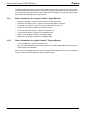
3.3
Standard Application Builder
3.3.1
Standard Application Builder / View Stages
c00280en.bmp
Fig. 3-4: View Stages
From View Stages, Stages 1-6 and a Backoff Stage are programmable for a given tool and application.
When the tool is started, each Stage having a programmed Fastening Sequence will be run in
succession based on the results from the previous stage. The Backoff Stage is used when the
tool is run in back-off direction or with the reverse button activated.
If a sequence has not been selected for a stage, then N/A is displayed for that stage. Otherwise
the Sequence number, description and icon are displayed. Sequences can be selected or
changed using the Select Seq (F1) soft key. This key is only valid when stages 1-6 are highlighted. The Fastening Sequence for the Backoff Stage is selected automatically.
The parameters for any stage can be programmed using the Parameters (F3) soft key. This key
is only valid when a Sequence has been selected for a given Stage.
24
PL12-1300 12/00
en03d141.fm, 30.01.2001
Electric Tool Control TME-100 Series
3.3.2
Cleco
Standard Application Builder / Select Sequence
c00281en.bmp
Fig. 3-5: Select Sequence
Fastening Sequences are selectable for a given Tool, Application and Stage by using the Control
and Monitor check boxes or selecting a Fastening Sequence directly from the dropdown listbox.
The following Fastening Sequences or Fastening Strategies are available:
Sequence 11
High Speed Rundown
Sequence 30
Torque Control/Angle Monitor
Sequence 50
Angle Control/Torque Monitor
Sequence 41
Angle Controlled Backoff
When a Sequence is selected the Control and Monitor check boxes and Fastening Sequence
listbox will both display the appropriate settings for the selected Sequence. An icon portraying
the selected Sequence is also displayed in the bottom right-hand corner.
en03d141.fm, 30.01.2001
PL12-1300 12/00
25
Electric Tool Control TME-100 Series
Cleco
The following table shows a matrix of the Control and Monitor schemes for each Sequence:
Sequence 11
Sequence 30
X
X
Sequence 50
Sequence 41
Control
Torque Control
Angle Control
X
Yield Control
Torque Control Reverse
Angle Control Reverse
X
Monitor
Torque Monitor
X
X
Angle Monitor
X
X
X
Yield Monitor
The Parameters (F3) soft key allows the user to program all associated control parameters for
the selected Sequence. It is only valid when a Sequence has been selected.
The following is a detailed description of each Fastening Sequence:
Sequence 11
High Speed Rundown
This tightening method is generally used as a fast pre-tightening stage. The torque transducer
integrated into the nutrunner measures the torque during the tightening. The value is processed
by the control system. When the defined Turnoff Torque is reached the nutrunner is shut off.
Thereafter the peak torque is measured during a dwell time and is then processed as the tightening torque of the bolt in the control system. This value is displayed on the Run Screen and can
be output to a printer or transmitted to other system components by data communication. When
the trigger torque is reached the torque curve is recorded and can be viewed and evaluated
using the oscilloscope function.
Sequence 30
Torque Control with Torque and Angle Monitoring
This tightening stage is normally preceded by a fast pre-tightening stage. The transducer integrated into the nutrunner measures the torque and the resolver measures the angle during the
tightening. The values are processed by the control system. When the threshold torque is
reached the angle count starts. When the Turnoff Torque is reached the nutrunner is shut off.
Thereafter the peak torque is measured during a dwell time and is then processed as the tightening torque of the bolt together with the evaluation of the rundown in the control system. This
value is displayed on the Run Screen and can be output to a printer or transmitted to other system components by data communication. When the trigger torque is reached the torque curve is
recorded and can be viewed and evaluated using the oscilloscope function.
Sequence 50
Angle Controlled Tightening with Angle and Torque Monitoring
This tightening sequence is generally preceded by a fast pre-tightening cycle. The transducer
integrated into the nutrunner measures the torque and the resolver measures the angle during
the rundown. The values are processed by the control system. When the Turnoff angle is
reached the nutrunner is shut off. Thereafter the final angle and the peak torque are measured
during a dwell time, and these tightening values for the bolt are then processed together with the
evaluation of the rundown in the control system. These values are displayed on the Run Screen
and can be output to a printer or transmitted to other system components by data communica-
26
PL12-1300 12/00
en03d141.fm, 30.01.2001
Electric Tool Control TME-100 Series
Cleco
tion. When the trigger torque is reached the torque curve is recorded and can be viewed and
evaluated using the oscilloscope function.
Sequence 41
Angle Controlled Back-off with Angle Monitoring
This fastening sequence is generally used to loosen a bolt a specified number of degrees. The
resolver integrated into the nutrunner measures the angle during the untightening. The value is
processed by the control system. When the Turnoff angle is reached the nutrunner is shut off.
Thereafter the final angle is measured during a dwell time and is then processed as the back-off
angle of the bolt together with the evaluation of the untightening in the control system. This value
is displayed on the Run Screen and can be output to a printer or transmitted to other system
components by data communication. In this stage the oscilloscope funktion is not supported.
3.3.3
Standard Application Builder / Parameters
c00282en.bmp
Fig. 3-6: Parameters
Parameters are programmable for a given Tool, Application and Stage based on the selected
Fastening Sequence and only the appropriate parameters are displayed for the selected Fastening Sequence.
The Next Stage (F2) key will increment to the next stage until it reaches the last stage having a
selected Sequence. It will then rollover to the first stage. In order to add a stage without a
selected Sequence the user must highlight the stage field and enter a number 1-6.
The following is a detailed description of each Fastening Sequence and associated Parameters:
Sequence 11
High Speed Rundown
This tightening method is generally used as a fast pre-tightening stage. The torque transducer
integrated into the nutrunner measures the torque during the tightening. The value is processed
by the control system. When the defined Turnoff Torque is reached the nutrunner is shut off.
Thereafter the peak torque is measured during a dwell time and is then processed as the tightening torque of the bolt in the control system. This value is displayed on the Run Screen and can
be output to a printer or transmitted to other system components by data communication. When
en03d141.fm, 30.01.2001
PL12-1300 12/00
27
Electric Tool Control TME-100 Series
Cleco
the trigger torque is reached the torque curve is recorded and can be viewed and evaluated
using the oscilloscope function.
The following parameters are programmable from the Standard Application Builder:
•
Fastening Sequence = 11
•
Trigger Torque (Nm) = trigger torque, beginning of measurement for the graphic display.
•
Turnoff Torque (Nm) = turnoff torque for the pre-tightening stage.
•
Speed = max speed of the nutrunner during the pre-tightening stage.
Parameter Name
Range
Default
Fastening Strategy
Sequence 11
High Speed Rundown
Trigger Torque [Nm]
0 to Tool Max
0.0
Turnoff Torque [Nm]
Trigger to Tool Max
0.0
Speed Stage 1 [RPM]
0 to Tool Max
80% of Tool Max
Sequence 30
Torque Control with Torque and Angle Monitoring
This tightening stage is normally preceded by a fast pre-tightening stage. The transducer integrated into the nutrunner measures the torque and the resolver measures the angle during the
tightening. The values are processed by the control system. When the threshold torque is
reached the angle count starts. When the Turnoff Torque is reached the nutrunner is shut off.
Thereafter the peak torque is measured during a dwell time and is then processed as the tightening torque of the bolt together with the evaluation of the rundown in the control system. This
value is displayed on the Run Screen and can be output to a printer or transmitted to other system components by data communication. When the trigger torque is reached the torque curve is
recorded and can be viewed and evaluated using the oscilloscope function.
The following parameters are programmable in the Standard Application Builder:
28
•
Sequence input value = 30
•
Trigger Torque (Nm) = trigger torque, beginning of measurement for the graphic display.
•
Threshold Torque (Nm) = threshold torque, beginning of angle counting
•
Turnoff Torque (Nm) = shut-off torque for the stage.
•
Torque High Limit (Nm) = max torque, high limit for torque reached.
•
Torque Low Limit (Nm) = min torque, low limit for torque reached.
•
Angle High Limit (deg) = maximum angle, high limit for angle reached. The nutrunner will
stop if this value is exceeded
•
Angle Low Limit (deg) = minimum angle, low limit for angle reached.
•
Speed = max speed of the nutrunner during the tightening stage.
Parameter Name
Range
Default
Fastening Strategy
Sequence 30
Torque Control/
Angle Monitor
Trigger Torque [Nm]
0 to Tool Max
0.0
Threshold Torque [Nm]
0 to Tool Max
0.0
Torque Low Limit [Nm]
0 to Tool Max
0.0
PL12-1300 12/00
en03d141.fm, 30.01.2001
Electric Tool Control TME-100 Series
Cleco
Parameter Name
Range
Default
Turnoff Torque [Nm]
Low Limit to Tool Max
0.0
Torque High Limit [Nm]
Turnoff to 9999
0.0
Angle Low Limit [Deg]
0 to 9999
0.0
Angle High Limit
Low Limit to 9999
0.0
Speed [RPM]
0 to Tool Max
50
Sequence 50
Angle Controlled Tightening with Angle and Torque Monitoring
This tightening sequence is generally preceded by a fast pre-tightening cycle. The transducer
integrated into the nutrunner measures the torque and the resolver measures the angle during
the rundown. The values are processed by the control system. When the Turnoff angle is
reached the nutrunner is shut off. Thereafter the final angle and the peak torque are measured
during a dwell time, and these tightening values for the bolt are then processed together with the
evaluation of the rundown in the control system. These values are displayed on the Run Screen
and can be output to a printer or transmitted to other system components by data communication. When the trigger torque is reached the torque curve is recorded and can be viewed and
evaluated using the oscilloscope function.
The following parameters are programmable in the Standard Application Builder:
•
Sequence input value = 50
•
Trigger Torque (Nm) = trigger torque, beginning of measurement for the graphic display
•
Threshold Torque (Nm) = threshold torque, beginning of angle counting
•
Turnoff Angle (deg) = shut-off angle for the stage
•
Angle High Limit (deg) = maximum angle, high limit for angle reached
•
Angle Low Limit (deg) = minimum angle, low limit for angle reached
•
Torque High Limit (Nm) = max torque, high limit for torque reached and safety shut-off
•
Torque Low Limit (Nm) = min torque, low limit for torque reached
•
Speed = max speed of the nutrunner during the tightening stage
Parameter Name
Range
Default
Fastening Strategy
Sequence 50
Angle Control/
Torque Monitor
Trigger Torque [Nm]
0 to Tool Max
0.0
Threshold Torque [Nm]
0 to Tool Max
0.0
Torque Low Limit [Nm]
0 to Tool Max
0.0
Torque High Limit [Nm]
Low Limit to Tool Max.
0.0
Angle Low Limit [Deg]
0 to 9999
0.0
Turnoff Angle [Deg]
Low Limit to 9999
0.0
Angle High Limit
Turnoff angle to 9999
0.0
Speed Stage [RPM]
0 to Tool Max
50
en03d141.fm, 30.01.2001
PL12-1300 12/00
29
Electric Tool Control TME-100 Series
Cleco
Sequence 41
Angle Controlled Back-off with Angle Monitoring
This fastening sequence is generally used to loosen a bolt a specified number of degrees. The
resolver integrated into the nutrunner measures the angle during the untightening. The value is
processed by the control system. When the Turnoff angle is reached the nutrunner is shut off.
Thereafter the final angle is measured during a dwell time and is then processed as the back-off
angle of the bolt together with the evaluation of the untightening in the control system. This value
is displayed on the Run Screen and can be output to a printer or transmitted to other system
components by data communication. In this stage the oscilloscope function is not supported.
The following parameters are programmable in the Standard Application Builder:
•
Sequence input value = 41
•
Turnoff Angle (deg) = shut-off angle, back-off angle
•
Angle High Limit (deg) = maximum angle, high limit for angle reached.
•
Angle Low Limit (deg) = minimum angle, low limit for angle reached.
•
Speed = max speed of the nutrunner during the back-off stage.
Parameter Name
Range
Default
Fastening Strategy
Sequence 41
Angle Control in Reverse
Angle Low Limit [Deg]
0 to 9999
0.0
Turnoff Angle [Deg]
Low Limit to 9999
0.0
Angle High Limit
Turnoff angle to 9999
0.0
Speed Stage [RPM]
0 to Tool Max
500
Backoff Using Reverse Switch (Sequence 41 or Sequence 46)
The Backoff stage is automatically set to Sequence 46 for a tubenut tool and Sequence 41 for all
others. The automatic selection of a tube nut tool depends on a "T" in the tool model number.
That means, if a "T" appears in the model number a tube nut tool is expected. This fastening
sequence is selected when the tool is run in the reverse or untighten direction. It is also automatically used to return a tubenut tool to the home position on every other trigger pull. The resolver
integrated into the nutrunner measures the angle during the untightening. The measured angle
value is processed by the control system. When the Turnoff angle is reached the nutrunner is
shut off. For a tubenut tool, the Turnoff angle is programmed so that the attachment will always
turn far enough to reach the home position and stop based on the torque reaction against the
pawl.
The following parameters are programmable in the Standard Application Builder:
30
•
Speed [rpm] = Max speed of the nutrunner during the backoff stage.
•
LED flashing in reverse = If yes, the tool LED's will blink when the tool is in reverse.
•
NOK after reverse = If yes, the controller will report an NOK if the tool is run in reverse.
Parameter Name
Range
Default
Speed Stage [RPM]
0 to Tool Max
500 or 30% of Tool Max
(tubenut)
LED flashing in reverse
Yes/No
No
NOK after reverse
Yes/No
No
PL12-1300 12/00
en03d141.fm, 30.01.2001
Electric Tool Control TME-100 Series
Cleco
The backoff parameters that are not displayed are set to values as in the table below.
Parameter Name
Sequence 41
Sequence 46
Start delay time [mS]
0
0
Start spike time [mS]
0
0
Max. Fastening time [mS]
10000
10000
End delay time [mS]
30
30
Torque Filter Factor
1
1
Torque Target
---
3,5% of Tool max. Torque
Torque High Limit
---
10% of Tool max. Torque
Angle Low Limit
0
0
Angle Target
9999
370
Angle High Limit
9999
380
For at tube nut tool the maximum speed for backoff ist 30% of Tool Max Speed. It is not possible
to enter a higher value.
3.3.4
Standard Application Builder / Advanced Parameters
c00283en.bmp
Fig. 3-7: Advanced Parameters
The user can enter the Advanced Parameters using the Advanced (F3) soft key from the Parameter screen. These parameters are identical regardless of the selected Fastening Sequence.
The Next Stage (F2) key will increment to the next stage until it reaches the last stage with a
selected Sequence. It will then rollover to the first stage. In order to add a stage without a
selected Sequence the user must highlight the stage field and enter a number 1-6.
en03d141.fm, 30.01.2001
PL12-1300 12/00
31
Electric Tool Control TME-100 Series
Cleco
Advanced Parameters
3.3.5
•
Start delay time [mS] = time delay before the stage will start.
•
Start spike time [mS] = time delay for the control system to start measuring torque after the
stage starts.
•
Max. Fastening time [mS] = max time for the tool to run during the stage.
•
End delay time [mS] = time delay from tool turnoff until shut-off of measured value recording.
•
Torque Filter Factor = used for torque averaging.
•
If NOK go to stage = gives the control system direction if the stage is NOK.
•
Rundown Printout = gives the control system direction for when to print.
Advanced Parameters
Default
Range of Values
Start delay time [mS]
0
0 - 999
Start spike time [mS]
0
0 - 999
Max. Fastening time [mS]
10000
1 - 60000
End delay time [mS]
30
0 - 999
Torque Filter Factor
1
1, 2, 4, 8, 16, 32
If NOK go to stage
Stop
Next; Error; Stop; 1; 2; 3; 4; 5; 6
Rundown Printout
None
OK; NOK; All; None
Advanced Application Builder / Application Matrix
c00284en.bmp
Fig. 3-8: Application Matrix
The Application Matrix is a display matrix of 8 Applications vs. 6 Stages showing the selected
Sequence number for each stage. It gives the user an overview of controller programming in a
single screen.
32
PL12-1300 12/00
en03d141.fm, 30.01.2001
Electric Tool Control TME-100 Series
3.3.6
Cleco
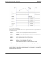
Advanced Application Builder / Inputs
c00285en.bmp
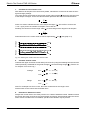
Fig. 3-9: Inputs
c00288en.bmp
Fig. 3-10: Input Timing Diagram
en03d141.fm, 30.01.2001
PL12-1300 12/00
33
Electric Tool Control TME-100 Series
Cleco
Eight optically isolated, +24V inputs are available at the Phoenix input connector under the right
side door and are defined as follows:
Inputs 0-2
Application Select 0-2: Application Selects 0-2 are used to select Applications 1-8
using a binary count of 0-7 where Applicaton Select 0 is the least significant bit.
This feature overrides application changes from the keypad.
Input 3
Tool Start (LCD and Outputs also clear): Starts the tool. Works in parallel with the
tool start switch.
Input 4
Activates the inputs I0 to I2 and I6.
Input 5
Tool Reverse: When active prior to tool start, the tool will run counter-clockwise
using the Backoff Strategy. Works in parallel with the tool reverse actuator.
Input 6
Tool Enable: When active allows the tool to start in conjunction with Tool Start.
Input 7
Synchronization Input: When active allows the tool to start from stage to stage in
conjunction with Tool Start.
All inputs are active high. They are referenced to an isolated Input Common (pin 10). When
using the internal +24V (pin 1) to activate these inputs, you must connect Input Common (pin
10) and GND (pin 11).
3.3.7
Advanced Application Builder / Outputs
c00286en.bmp
Fig. 3-11: Outputs
34
PL12-1300 12/00
en03d141.fm, 30.01.2001
Electric Tool Control TME-100 Series
Cleco
c00287en.bmp
Fig. 3-12: Output Timing Diagram
Eight relay outputs are availiable at the Phoenix output connector under the right side door and
are defined as follows:
Output 0
Cycle OK: Active if Torque/Angle/Yield are within programmed limits.
Output 1
Cycle NOK: Active if Torque/Angle/Yield are outside limits or some other error has
occurred.
Output 2
Torque Low: Active if Peak Torque < Torque Low Limit
Output 3
Torque High: Active if Peak Torque > Torque High Limit
Output 4
Angle Low: Active if Final Angle < Angle Low Limit
Output 5
Angle High: Active if Final Angle > Angle High Limit
Output 6
Cycle Complete: Active whenever the fastening sequence is complete
Output 7
Synchronization Output: Active at the end of each stage to signal a stage is complete.
All relay outputs are active high. One side of all of the relay contacts is tied to a common supply
voltage point called Output Common (pin 2). When using the internal +24V (pin 1) as a source
for these outputs, you must connect Output Common (pin 2) and +24V (pin 1). The outputs will
then be referenced to GND (pin 11).
en03d141.fm, 30.01.2001
PL12-1300 12/00
35
Electric Tool Control TME-100 Series
3.3.8
Cleco
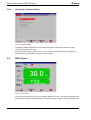
Advanced / System Settings
c00313en.bmp
Fig. 3-13: System Settings
The System Settings allows the user to assign the System a name and number as well as
change the system torque units.
The torque units can be set to Nm, Ft-Lb, In-Lb, or Kg-cm. When the units are changed, all
torque values are immediately changed to the new units.
3.4
RUN Screen
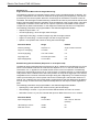
c00289en.bmp
Fig. 3-14: Run Screen
From the Run Screen the user can see rundown data as it occurs. The Torque and Angle readings are displayed with a background color corresponding to the status of each. The background
36
PL12-1300 12/00
en03d141.fm, 30.01.2001
Electric Tool Control TME-100 Series
Cleco
will be red if the value is too high, yellow if it is too low, and green if it is within limits. The current
tool model number, application name, and indicator labels are also displayed.
The desired Application (1-8) is selectable using the keypad.
The Oscilloscope (F2) soft key will display the Oscilloscope function for evaluating Torque and Angle
curves. It is automatically updated after each cycle.
3.5
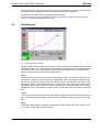
Oscilloscope
c00290en.bmp
Fig. 3-15: Oscilloscope Operation
The Oscillosope funktion displays a Torque vs. Angle curve after each complete rundown in the
tightening direction. The curve is colored in alternating blue and pink lines to indicate the different stages. A green box is also displayed on the trace to indicate the torque and angle limits.
There is a data point for each degree of angle rotation.
Zoom
Using the Zoom indicators on the left side of the display, a specific area of the torque trace can
be enlarged. Using the up/down arrow keys, highlight the "Left" zoom indicator. Using the left/
right arrow keys set the orange vertical line to the left extent of the desired zoom window. Then
highlight the "Right" zoom indicator and set the right extent ot the desired zoom window. Once
the window extents are set, pressing "Enter" will enlarge the trace to the desired zoom window.
Highlight the "Full" zoom indicator and press "Enter" to return the trace to the original unzoomed
size.
Cursor
The cursor (red cross-hatch) can be moved along the torque trace using the left and right arrow
keys. The actual torque and angle values of the cursor position are shown at the top ot the display.
Stage
The Stage softkey allows to select the corresponding stage by input of a stage number (0 to 6).
If you enter "0", the entire rundown is shown.
en03d141.fm, 30.01.2001
PL12-1300 12/00
37
Electric Tool Control TME-100 Series
Cleco
Rundown Indicator
At the bottom left of the display is the rundown indicator. The final torque and angle values are
displayed on either a green (OK) background or red (NOK) background.
Parameters
At the bottom of the display is a summary of the parameter settings for the rundown.
The Save softkey (F2) lets you print a hardcopy.
3.6
Communication
3.6.1
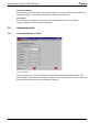
Communications / Printer
c00291en.bmp
Fig. 3-16: Printer
From this screen the user can configure the setup for the Parameter/Rundown Printer. The
Basic settings are Port, Baud rate, Data bits, Stop bits, Parity, and Protocol. In case a Centronics
Port is selected for the Printer all other fields are inactive.
38
PL12-1300 12/00
en03d141.fm, 30.01.2001
Electric Tool Control TME-100 Series
3.6.2
Cleco
Communications / Serial Data Transmission
c00292en.bmp
Fig. 3-17: Data Transmission
The Serial Data Transmission is sent after each cycle to the programmed COM port. The Basic
settings are Port, Baud rate, Data bits, Stop bits, Parity, and Protocol. The following table details
the transmission data:
Start
End
Length or Value
Description
1
1
42 hex
B
2
3
2 Digit ASCII
Tool Number
4
5
2 Digit ASCII
Parameter Set
6
17
12 Char ASCII
Date and Time (YYMMDDHHMMSS)
18
24
7 Digit ASCII
Peak Torque
25
31
7 Digit ASCII
Low Torque Limit
32
38
7 Digit ASCII
High Torque Limit
39
39
1 Char ASCII Status
Torque Status Flag
L = low
A = accept
H = high
40
46
7 Digit ASCII
Final Angle
47
53
7 Digit ASCII
Low Angle Limit
54
60
7 Digit ASCII
High Angle Limit
61
61
1 Char ASCII Status
Angle Status Flag
L = low
A = accept
H = high
en03d141.fm, 30.01.2001
PL12-1300 12/00
39
Electric Tool Control TME-100 Series
Cleco
Start
End
Length or Value
Description
62
62
1 Char ASCII Status
Overall Status Flag
A = accept
R = reject
63
64
2 Digit ASCII
Batch Count
(Only for Batch Count)
3.7
65
66
2 Digit ASCII
Batch Size
(User programmable)
(Advances only on ACCEPT)
67
67
0D hex
CR (carriage return)
68
68
0A hex
LF (line feed)
Tool Setup
c00293en.bmp
Fig. 3-18: Tool Memory
The Tool memory data is displayed for the selected tool and redundancy. Only the Field Torque
Calibration (+/- 20% of nominal) is editable. If no Tool memory is available, then all data is programmable.
To change the tool memory the (F2) soft key must be pressed and a warning message will be
displayed. Then all fields are programmable except Serial number, Manufacture date, and Total
Cycles. When the tool memory is changed, the user name is also written to the tool memory for
traceability.
In case a tool with memory is changed to another tool with memory of the same type the tool will
continue to work without any necessary changes. In case the tool is changed to a tool without
memory or to a different type, then after power on or when pressing the start switch a message
is displayed which prompts the user to verify the Tool Setup.
40
PL12-1300 12/00
en03d141.fm, 30.01.2001
Electric Tool Control TME-100 Series
Cleco
Pressing the Tool Library (F1) key will allow the user to select from a library of predefined tools.
This library can be used to program the tool parameters when tool memory is not available or to
change the existing tool memory values.
3.8
Tool Library
3.8.1
Tool Library
c00294en.bmp
Fig. 3-19: Tool Library
Using the arrow keys, move the orange highlight to the desired tool. Press ENTER to select that
model or ESC to exit. If a model is selected these new parameters will be used as the tool
parameters. Note that it is extremely important that the correct model is chosen to avoid damage to the tool or injury to the worker.
Use Page Up (F2) and Page Down (F3) when appropriate to view more tool models.
en03d141.fm, 30.01.2001
PL12-1300 12/00
41
Electric Tool Control TME-100 Series
3.8.2
Cleco
Tool Library / Custom
c00295en.bmp
Fig. 3-20: Custom Tool
Tools will be added to the Custom Tool Library when a tool that does not exist in the Tool Library
is used. Anytime data is entered in the Tool Setup screen that does not match data in the Standard Tool Library, the new tool will be added to the Custom Tool Library.
Using the arrow keys, move the orange highlight to the desired tool. Press ENTER to select that
model or ESC to exit. When a model is selected these new parameters will be used as the tool
parameters. Note that it is extremely important that the correct model is chosen to avoid damage to the tool or injury to the worker.
Use Page Up (F2) and Page Down (F3) when appropriate to view more tool models.
42
PL12-1300 12/00
en03d141.fm, 30.01.2001
Electric Tool Control TME-100 Series
3.9
Statistics
3.9.1
Statistics / Summary
Cleco
c00296en.bmp
Fig. 3-21: Statistical Summary
The user can view the Statistical Summary for the selected rundowns of any Tool or Application.
This summary includes high value, low value, range, average, standard deviation, and CpK for
Torque and Angle.
The Clear Summary (F3) soft key allows the user to delete the Statistics.
3.9.2
Statistics / Chronological History
c00297en.bmp
Fig. 3-22: Chronological History
en03d141.fm, 30.01.2001
PL12-1300 12/00
43
Electric Tool Control TME-100 Series
Cleco
The user can view the Chronological History for the selected rundowns of any Tool or Application. This history includes time, date, status, torque, and angle.
The Clear Chrono (F3) soft key allows the user to delete all rundowns.
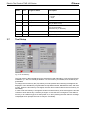
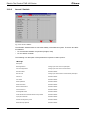
3.10
Diagnostics
3.10.1
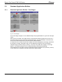
Inputs / Outputs
c00298en.bmp
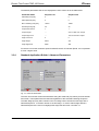
Fig. 3-23: Inputs / Outputs
Inputs and Outputs are divided into Internal and External I/O. The Internal I/O displayed on the
left side is used for tool start, direction, and Led outputs. The External I/O displayed on the right
side can be reached at the Phoenix connectors located under the side door. This screen will give
a live update of all system I/O. If a green box is shown next to the I/O description, then it is
active.
Otherwise the space next to the I/O description will be blank indicating it is inactive.
44
PL12-1300 12/00
en03d141.fm, 30.01.2001
Electric Tool Control TME-100 Series
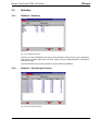
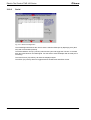
3.10.2
Cleco
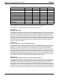
Tool / Calibration
c00299en.bmp
Fig. 3-24: Tool / Calibration
This test function cyclically recalibrates the system with the values used immediately before the
start of a rundown. The must be released for this function! The values "Calibration offset" and
"Calibration voltage" of the torque transducer are displayed. If redundancy is activated, the values of the second transducer are displayed. If a value is out of tolerance, it is shown in red.
Rated values and tolerances:
Value
Rated value
Tolerance
Calibration offset:
0V
+/-200 mV
Calibration voltage:
5V
+/-150 mV
en03d141.fm, 30.01.2001
PL12-1300 12/00
45
Electric Tool Control TME-100 Series
3.10.3
Cleco
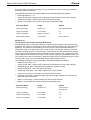
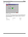
Tool / Voltages
c00300en.bmp
Fig. 3-25: Tool / Voltages
The table displays the measured voltages of a channel.
These are the most important supply voltages on the measuring board, required for proper
torque and angle measurement. Therefore, these must be monitored continuously. If a voltage is
out of tolerance, it is shown in red.
46
Designation voltage
Rated value
Tolerance
Logic voltage:
+5 V
+250 mV/-400 mV
Pos. analog Positive analog
voltage
+12 V
±600 mV
Neg. analog Negative analog
voltage
-12 V
±600 mV
PL12-1300 12/00
en03d141.fm, 30.01.2001
Electric Tool Control TME-100 Series
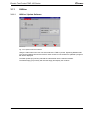
3.10.4
Cleco
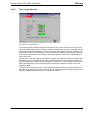
Tool / Angle Encoder
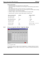
c00301en.bmp
Fig. 3-26: Tool / Angle Encoder
The tool start switch starts the spindle with a speed of 30 % of the maximum. After one revolution of the output shaft (set angle 360 deg), measured with the tool resolver, it is stopped. During
a permanently adjusted dwell time of 200 ms any further angle pulses occurring are traced. The
total result is shown as "Actual Angle". The "Shut-off Torque" displayed is the torque prevailing
at shut-off or the maximum value reached during the dwell time if that value is higher than the
torque at shut-off.
If the test run is not terminated by a monitoring criterion, the total result equals or is higher than
360 degrees and is evaluated as okay ("OK"). Monitoring criteria are the torque of transducer 1
and a monitoring time. If the torque of transducer 1 exceeds 15 % of its calibration value (even
during the dwell time), or if the monitoring time of 5 seconds is elapsed, the test run is terminated with "NOK".
The user must check himself, if the output shaft has actually turned by the value indicated (e. g.
put mark on the spindle). If the angle reached by the output shaft does not agree with the value
displayed, either the angle factor is or the resolver is defective.
en03d141.fm, 30.01.2001
PL12-1300 12/00
47
Electric Tool Control TME-100 Series
3.10.5
Cleco
Tool / TQ Measurement
c00302en.bmp
Fig. 3-27: Tool / TQ Measurement
This test function recalibrates the system with the values used immediately before the start of a
rundown. The spindle must therefore be released still when this function is called up! Then the
tool is started at zero speed and the torque is continuously measured and displayed. The field
"Current torque" displays the current torque, "Peak torque" displays the highest value measured
since the start of the function. If "Redundancy" is activated, the values of the second transducer
are also displayed.
3.10.6
Tool / Speed
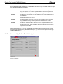
c00314en.bmp
Fig. 3-28: Tool - Speed
When you press the tool start switch, the spindle starts with maximum speed. The current output
shaft speed is displayed. To achieve this, the angle factor must have been entered correctly,
48
PL12-1300 12/00
en03d141.fm, 30.01.2001
Electric Tool Control TME-100 Series
Cleco
since the integrated speed measurement is derived from the resolver signals. When you release
the start switch the spindle stops. As a safety function the torque is monitored by the tool transducer. If it exceeds 15 % of its calibrated value, the tachometer function is terminated.
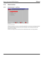
3.10.7
Arcnet / Map
c00303en.bmp
Fig. 3-29: Arcnet / Map
The ARCNET map displays information on the current number of participants in the network,
their ARCNET-ID, status, serial and software number and identification. The display is continuously updated, e. g. if the connection with a participant is interrupted, it is removed from the
table, or if a new participant is added, it is added to the ARCNET table.
en03d141.fm, 30.01.2001
PL12-1300 12/00
49
Electric Tool Control TME-100 Series
3.10.8
Cleco
Arcnet / Statistic
c00304en.bmp
Fig. 3-30: Arcnet / Statistic
The ARCNET statistics allow to check the stability of the field bus system. There are two different statistics:
•
For all external hardware components (bridges, TMs)
•
For the station controller
The following is a description of the parameters required for stable operation.
TM Bridge
Description
50
Reconfigurations
Change upon each reset of a participant
Own reconfigurations
Change upon each reset or severe failure
Excessive NAK
Should be stable
New next ID
Change upon switsch-off/on of downstream participant
CRC error
Should be stable
Lost Token
Should be stable
Send repetitions
Should be stable
Send termination
Should be stable
Receive terminations
Should be stable
Command errors
Should be stable
Unassignable ACKs
Should be stable
ACKs with Bit 14/15-Packets without CPT protocol
Should be stable
Input queue overflow
Should be stable
Packet not assigned by node
Should be stable
Discarded input packets
Should be stable
PL12-1300 12/00
en03d141.fm, 30.01.2001
Electric Tool Control TME-100 Series
Cleco
Host Driver Statistics
Reconfiguration
Change upon each reset of a participant
Host reconfiguration
Change upon each reset or severe failure
CRC error
Should be stable
Outbound packets - Inbound packets - Next ID
Change upon switch-off/on of downstream participant
Excessive NAK
Should be stable
Lost Token
Should be stable
Statistics of ARCNET Manager
Broadcasts received Synochronous starts Stopped synchronous starts CRC error
Should be stable
Timeout A
Should be stable
Timeout B
Should be stable
Wrong ARCNET ID received
Should be stable
Packets not for host
Should be stable
ACKs in READY status
ACKs in ERROR status
Should be stable
Unassignable ACK
Should be stable
ACKs with Bit 14/15
Packets without CPT protocol
Should be stable
Input queue overflow
Should be stable
Packet not assigned by node
Should be stable
Discarded input packets
Should be stable
en03d141.fm, 30.01.2001
PL12-1300 12/00
51
Electric Tool Control TME-100 Series
3.10.9
Cleco
Serial
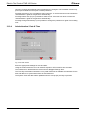
c00305en.bmp
Fig. 3-31: Serial Port Diagnostics
The serial diagnostics allows the user to test the selected COM port by displaying sent (blue
text) and received data (red text).
The Start Hardware Test (F1) soft key will send ten bytes and toggle the TXD line. It will read
back the bytes based on the RXD signal. For this test an external Adapter with shorted pins is
necessary.
The Clear Screen (F2) soft key will clear the displayed bytes.
The ASCII (F3) soft key allows to toggle between hexadecimal and ASCII format.
52
PL12-1300 12/00
en03d141.fm, 30.01.2001
Electric Tool Control TME-100 Series
3.11
Utilities
3.11.1
Utilities / Update Software
Cleco
c00306en.bmp
Fig. 3-32: Update Controller Software
Using the radio buttons the user can select either the TME or just the Tightening Module itself.
The current installed versions are listed for each module. As the software is updated a progress
bar will be displayed.
The Start Update (F2) soft key will load the selected file into the selected module.
The Read Floppy (F3) soft key will read the floppy and display the contents.
en03d141.fm, 30.01.2001
PL12-1300 12/00
53
Electric Tool Control TME-100 Series
Cleco
3.12
Administration
3.12.1
Administration / Load/Save
c00313en.bmp
Fig. 3-33: Load / Save
Using the check boxes, the user can select the parameters to load or save to the floppy diskette.
The Load from Floppy (F2) soft key will search the floppy for the selected parameters and
update them accordingly.
The Save to Floppy (F3) soft key will save the selected parameters to the floppy diskette.
54
PL12-1300 12/00
en03d141.fm, 30.01.2001
Electric Tool Control TME-100 Series
3.12.2
Cleco
Administration / Print
c00308en.bmp
Fig. 3-34: Print
Using the check boxes, the user can select the parameters to print. These will be sent to the
printer defined in the Communications setup or to a file on the floppy diskette if selected.
The Cancel Print (F2) soft key will cancel the print job immediately.
The Print (F3) soft key will start printing. Upon printing a message will be displayed to show the
number of pages being printed.
3.12.3
Administration / Password
c00309en.bmp
Fig. 3-35: Password
The Password displays the active users and corresponding rights. There are different rights
available for Programming, Statistics, Diagnostics and Administration. The date and time of the
en03d141.fm, 30.01.2001
PL12-1300 12/00
55
Electric Tool Control TME-100 Series
Cleco
last entry changes automatically when parameters are changed. The Password function supports up to ten different users plus a master password.
Pressing Add User (F1) it is possible to add a new user. If the first user does not activate the
"Administration" rights he will get them automatically.
Pressing Delete User (F2) it is possible to delete a user. If the last user does not have the
"Administration" rights he will get them automatically.
Pressing Change Password (F3) it is possible to change the password or rights of an existing
user.
3.12.4
Administration / Date & Time
c00310en.bmp
Fig. 3-36: Date & Time
Enter the appropriate settings for time and date.
Using the radio buttons the user can select European or US format for time and date.
The Checkbox for Winter/Summer will account for Daylight Savings Time.
The Time Synchronization Checkbox is only valid if Ethernet is available and will allow for the
time and date to be synchronized from an external device.
The System Time and date will be updated when the Accept (F3) soft key is pressed.
56
PL12-1300 12/00
en03d141.fm, 30.01.2001
Electric Tool Control TME-100 Series
Cleco
4
Statistics
4.1
Understanding Statistics
Your unit provides a wide array of statistical and data reports (charts) for the control of manufacturing processes. The following provides a description of the control chart for variables and an
outline of the procedure for its use. Known as the -R chart (pronounced X-bar-R), the chart for
variables can be used whenever a quality characteristic can be measured and expressed by a
numerical value. When properly used, it can bring substantial improvement in product quality
and a reduction of scrap and rework.
When we control a process, we monitor the variation of the characteristics that are important to
the product. During production, samples from the process are measured. By plotting the results
of these measurements on the control chart, we are able to see if the process is operating in a
stable manner (in a state of statistical control), or if the pattern has been disturbed by an event
that drives the process out of control. In other words, the control chart tells us what the process
is doing - when to take action and when to leave it alone.
Although it is a powerful tool, the -R Control Chart is easy to use. Only an understanding of a
few basic statistical concepts and the use of simple arithmetic is needed.
4.1.1
The Nature of Variation
Variations in measured product are always present because of random fluctuations and inconsistencies in machines, material, and operator performance. No two items produced are exactly
alike.
When variation is random and stable, the process is in a state of statistical control (see graph
4-1a). The process has an identity, and its performance is predictable. The stable pattern of variation is caused by conditions that are inherent to the manufacturing system, such as spindle run
out, bearing clearances, differences in material properties, accuracy of measuring equipment,
and operator performance. We call this "common cause" variation.
When variation is sporadic and unstable, the process is out of statistical control (see graph
4-1b). The process loses its identity and is no longer predictable. The unstable pattern is
caused by such events as tool breakage, tool wear, bad material, and operator error. This is
called "special cause" variation.
Fig. 4-1: a) Common Cause Variation
4.1.2
Fig. 4-1: b) Special Cause Variation
The Normal Curve
Most processes in statistical control have a fixed pattern of variation. The mathematical curve
that describes this pattern is known as the normal curve (see graph 4-2a). The normal curve is
symmetrical about the average. It is high in the middle and becomes smaller as the distance
en04d141.fm, 30.01.2001
PL12-1300 12/00
57
Electric Tool Control TME-100 Series
Cleco
from the average increases. Since the shape resembles a bell, it is sometimes referred to as a
bell curve.
The normal curve is defined by two conditions - the average of all items produced, and the
amount of variation from the average. We can think of these as the center and width of the bell,
respectively. The center is the arithmetic average of all items produced. The width is expressed
in terms of the standard deviation which is a statistical calculation for the amount of variation
from the average. The standard deviation, represented by the Greek letter sigma (σ), holds a
fixed relationship to the normal curve, as follows (see graph 4-2b):
•
68% of all items produced will be within +1σ of the average (two sigma spread).
•
95% will be within +2σ of the average (four sigma spread).
•
99.7% will be within +3σ of the average (six sigma spread).
These two characteristics - the average and the standard deviation - provide the foundation for
statistical process control. By taking sample measurements during production, we can predict
the average value and the amount of variation for all items produced.
Avg.
3σ
2σ
1σ
Avg. 1σ
2σ
3σ
68%
95%
99.7%
Fig. 4-2: a) The Normal Curve
4.1.3
Fig. 4-2: b) Areas Under The Normal Curve
The Procedure
The procedure for establishing a statistical process control program consists of three phases.
The first is to obtain statistical control - a state of random and stable variation. The second is to
establish process capability. A state of statistical control in itself does not assure that the process
is capable of meeting the specification. The limits of variation must be equal to or less than the
total specification tolerance. The third is to monitor the process throughout production using the
control chart, to detect and correct conditions that upset the stable pattern of variation.
Use of the -R Control Chart includes the following steps:
1.
Select the Characteristic
Since a separate chart is required for each characteristic, practical considerations limit use to
selected requirements. A good candidate is a characteristic that is important to the function of
the item. Others include those that are causing a high cost loss because of scrap or rework, and
those that require evaluation by destructive testing.
2.
Designate the Sample Size
It is usually desirable to keep the sample size small so that variation within the sample is at a
minimum, but not so small that statistical validity is lost. The control chart described in this document is structured for a sample size of five units. If a sample other than five is selected, the manufacturing or quality engineer can provide alternate factors for use in calculating the control
limits and standard deviation (Steps 8 and 10).
58
PL12-1300 12/00
en04d141.fm, 30.01.2001
Electric Tool Control TME-100 Series
3.
Cleco
Designate the Sample Frequency
Selection of the sample frequency should be based on economic considerations for the cost of
measurements and the potential loss that may occur if samples are not taken often enough.
Early in the production run, samples should be taken more frequently and then extended after
satisfactory control is verified. The frequency may be expressed as a time interval or as a portion of quantities produced.
4.
Assure Measurement Accuracy
Measurement accuracy is mandatory for successful statistical control. Measuring and test equipment must be of a type suitable for the characteristic being evaluated, and must be calibrated
and properly used. Decisions resulting from the analysis of a control chart will be no better than
the measurement data.
5.
Complete the Data Sheet Headings
It is important that all heading entries on the data sheet be completed. They include the part
number and description, the operation performed, the name of the operator, the machine or
equipment used, and the specification limits. The data sheet and control chart can provide evidence of quality for use by the Quality Assurance organization if the information is properly
recorded and traceable to the products manufactured.
6.
Start Production
Average
Take samples of five units (preferably consecutive units produced) at the designated frequency,
and record each measurement (X) on the data sheet. For each sample of five calculate the average ( ) and range (R), and plot the results on the chart (see graph 4-3).
- Add the five measurements and divide the sum
by five. For a sample of five, it is often easier to multiply the sum by two and move the decimal one place
to the left.
20
X
16
12
R - Substract the smallest measurement from the
largest. (Note that the range can never be negative.)
Range
8
4
R
0
Fig. 4-3: Entries for Range and Average
en04d141.fm, 30.01.2001
PL12-1300 12/00
59
Electric Tool Control TME-100 Series
7.
Cleco
Calculate Process Center Lines
After data for 20 samples of five have been plotted, calculate the center lines for both the average and range plottings.
The center line for the average chart is known as the grand average ( ) and is the average of all
of the sample averages. This is the value that best represents the size of all measurements:
ΣX
n
X
where Σ is used to indicate the sum of the sample averages, ( ), (be careful to observe the
+ and - signs), and n the number of samples, in this case 20.
Similarly, the center line for the range chart ( ) is the average of the ranges for all samples.
ΣR
n
R
Average
Draw solid lines on the control chart for values representing
20
UCL X
16
X
12
LCL X
Range
8
and
(see graph 4-4).
UCL R
4
R
0
LCL R
Fig. 4-4: Drawing The Center Lines And Control Limits
8.
Calculate Control Limits
Calculate the upper and lower control limits (UCL and LCL) using the following formulas and the
values previously calculated for the grand average ( ) and the average range ( ). (Factors are
for samples of five units only.)
Average
UCL
LCL
Range
UCL
x
x
R
LCL R
X +0.577(R)
X
0.577(R)
X +2.114(R)
0
Note: For a sample size of six or less, the lower control limit for the range is zero.
Plot the limits on the control chart as broken lines.
9.
Evaluate for Statistical Control
Analyze the control chart to see if the process is in a state of statistical control. Variation should
be random about the center lines for both averages and ranges, with all points within the control
limits. If these conditions are not satisfied, special cause variation may be present.
60
PL12-1300 12/00
en04d141.fm, 30.01.2001
Electric Tool Control TME-100 Series
Cleco
Sometimes a process takes time to stabilize after start-up. If the indication of special cause variation occurs only in the first few samples, continue to take several more samples and recalculate
the limits by omitting the special cause values. However, if the indications of special cause variation occur other than at start-up, action should be taken to identify and correct the cause, and
the process re-started.
10. Evaluate for Process Capability
When the process is in a state of statistical control, estimate the standard deviation (σ) using the
value for the average range ( ) previously calculated. (The factor is for samples of five units
only.)
Estimate of σ
=
R
2.326
If the 6σ spread is equal to or less than the total specification tolerance, the process is capable. It will produce at
least 99.7% of all items to specification.
Avg.
6σ
Spec. Tolerance
Fig. 4-5: Capable Process
If the 6σ spread is greater than the specification tolerance, three options are available:
•
Improve the system - reduce variability
•
Increase the specification tolerance
•
Continue production and sort by 100% inspection
11. Center the Process
After the 6σ capability requirement is satisfied, it may be desirable to center the process so that
the process average is close to the middle of the specification tolerance. This can usually be
accomplished by a simple machine or tooling adjustment. If the magnitude of the adjustment is
known, the center line and the control limit lines for the average plotting may be moved a distance equal to the adjustment, and re-verified after 20 additional samples are plotted. Centering
the process does not affect the center line or control limits for the range, so no adjustment
should be made to them.
12. Realign the Inspection Activity
When properly controlled, production can usually continue without the need for 100% inspection. More attention can be placed on process surveillance and audits of operator performance.
However, certain safety critical requirements will justify an independent verification.
13. Maintain Control
The operator shall continue to take sample measurements and plot the results on the control
chart. As long as the pattern of variation remains random and within the control limits, no action
is taken. However, if an indication of special cause variation is detected, the trouble should be
identified and corrected (see graph 4-6). An indication of special cause variation can result from
conditions such as tool wear, tool breakage, defective material, measurement error, a mistake in
en04d141.fm, 30.01.2001
PL12-1300 12/00
61
Electric Tool Control TME-100 Series
Cleco
calculating the average or range for a sample, and plotting a point on the control chart incorrectly.
Special cause variation may be indicated by one of the following situations:
•
A point outside a control limit.
•
A shift, with several consecutive points inside a control limit but on the same side of the center line.
•
A trend of consecutive points that moves steadily toward a control limit.
Outside of Limit
Shift
Trend
Fig. 4-6: Indications of Special Cause Variation
Since we are controlling by evaluating only small sample sizes from the process, the criteria for
continuing production must be the control limits. For this reason, we do not place the specification limits (which are recorded on the data sheet) on the control chart.
4.1.4
System Improvement
There are always two risks associated with statistical control. The first is the risk of accepting
bad product, and the second is the risk of rejecting good product. Both are undesirable, but our
primary concern is usually the first since it has a direct impact on customer satisfaction.
The six sigma spread of the process described in this procedure is in general use throughout
American industry. When properly applied, it assures us that at least 99.7% of all units produced
will meet specification. This relates to a risk of delivering three substandard units for each thousand produced. While this provides much better quality than can be obtained with an uncontrolled process and 100% inspection, it may not be good enough in the future as competition
becomes stronger in the world market.
So it's important that we continue to improve the manufacturing system - to reduce the influence
of conditions that affect variations in the performance of people, machines, and materials (see
graph 4-7). There will be practical and economic limitations to this effort, but to the extent that
we can further reduce process variation we will increase the probability that all delivered product
meets the specification.
Variation
Variation
Spec. Toler.
Spec. Toler.
Fig. 4-7: Improving The System By Reducing Variation
62
PL12-1300 12/00
en04d141.fm, 30.01.2001
Electric Tool Control TME-100 Series
4.2
Cleco
Statistic Symbols
•
σ
•
=
standard deviation (or sigma)
=
mean (or average)
•
R
=
range
•
Cp
=
Capability of Process
•
Cpk
=
Capability index
•
n
=
number of runs
•
Sub Sz=
Subgroup size
•
Y
=
Torque summary run data
•
A
=
Angle summary run data
(Note: See glossary for definitions)
en04d141.fm, 30.01.2001
PL12-1300 12/00
63
Electric Tool Control TME-100 Series
64
Cleco
PL12-1300 12/00
en04d141.fm, 30.01.2001
Electric Tool Control TME-100 Series
5
Cleco
Glossary
accepted data
data that fall within the acceptable limits in a fastening
strategy
accepted rundown
a run cycle within limits
angle capability indexes
a measure of acceptable variation of final angle values in
a fastening process
angle control
a fastening strategy by which you are controlling a tool by
predetermined angle limits
angle encoder
a device that measures the angle of rotation
angle high
active if final angle > angle high limit
angle high limit (AHL)
the maximum acceptable angle for a run cycle
angle limits
the range between the maximum and minimum acceptable angle for one cycle
angle low
active if final angle < angle low limit
angle low limit (ALL)
the minimum acceptable angle for a run cycle
angle monitor
a fastening strategy by which you are monitoring a tool by
predetermined angle limits
angle reject
a cycle rejected when the acceptable angle is not
achieved
application
a programmed setting of the unit for a given application;
TME 100 has eight application settings. Often referred to
as product group
application select 0-2
application selects 0-2 are used to select applications 1-8
using a binary count of 0-7 where app. sel. 0 is the least
significant bit
baud rate
the frequency at which the unit communicates
capability of process (Cp)
The ratio of the process tolerance to 6 standard deviations. Ranges from 0.0 to infinity with larger values indicating a more capable process. (Often referred to as
Process Potential Index or Inherent Capability Index.)
capability index (Cpk)
An index combining the process potential and the measure of the difference between process and the specification mean. CPK will equal Cp if the process mean is
centered on the target (nominal) specification value; if
CPK is negative, the process mean (X-Bar) is outside the
specification limits; if CPK is between 0 and 1, then some
of the 6 sigma spread will fall outside of the specifications;
if CPK is larger than 1 then the 6 sigma spread is completely within the specification tolerance.
en05d141.fm, 30.01.2001
PL12-1300 12/00
65
Electric Tool Control TME-100 Series
66
Cleco
control parameters
the parameters that define the fastening strategy
sequence for a given tool
cycle complete
active whenever tool is not running
cycle NOK
active if torque/angle/yield are outside limits or some
other error has occurred
cycle OK
active if torque/angle/yield are within programmed limits
cycle start switch
the switch on a tool that initiates a run cycle
default parameters
parameters automatically selected by the unit
desired final torque
the final torque desired in a fastening process (referred to
as torque setpoint)
end delay time [ms]
time delay from the tool turnoff until the torque measurement ends
engineering units
units of torque measurement
external transducer
a transducer physically located on the outside of a tool
fastener rotation
direction in which a fastener rotates
fastening strategy
a strategy used to control or monitor a fastening process
final angle
the final angle desired in a fastening process
histogram
a printout generated from statistical data output
if NOK go to stage
gives the control system direction if the stage is NOK
internal transducer
a transducer physically located inside the tool
LCD screen
the screen on the unit that provides directions to programming the unit
LED flashing in reverse
if yes, the tool LED's will blink when the tool is in reverse
LED screen
the screen on the unit that provides the readout data from
a run cycle
load
refers to the amount of torque applied to a device or tool
main menu
the first menu that appears on LCD screen
marking output
output from paint marker solenoid after each cycle
master transducer
a transducer used as a benchmark to calibrate another
transducer
max. fastening time [mS]
max time for the tool to run during the stage
mean (Xbar)
the average of all readings taken in a sample
NOK after reverse
if yes, the controller will report an NOK if the tool is run in
reverse
peak torque
the maximum torque achieved in a run cycle
PL12-1300 12/00
en05d141.fm, 30.01.2001
Electric Tool Control TME-100 Series
Cleco
port
the socket used for connecting a cable or peripheral
equipment
power supply
a unit used to supply power to an electrical device
pulses per degree
number of encoder pulses generated by the tool when
rotating the head exactly 1 degree or 1/360 of a revolution
range (R)
a statistical measurement of the difference between the
lowest and highest reading taken in a sample
redundant transducer
secondary transducer used to read torque
redundant transducer calibration
the calibration process of the secondary transducer
reject interlock
the stopping of further operation of the system after a predetermined number of rejected cycles has occurred
rejected data
the data generated by unacceptable rundowns
rejected rundown
a rundown that has not met the criteria of a fastening
strategy
remote parameter select
a remote device that bypasses the parameter select button on your unit
rundown printout
gives the control system direction for when to print
run number
number of accepted and rejected rundowns
second transducer
frequently referred to as the redundant transducer
sequence 11
high speed rundown
sequence 30
torque control/angle monitor
sequence 50
angle control/torque monitor
sequence 41
angle controlled backoff
speed
max speed of the nutrunner during the tightening stage
standard deviation (σ)
the measurement of the scatter of the population around
a mean
start delay time [ms]
time delay before the stage will start
start spike time [ms]
time delay for the control system to start measuring
torque after the stage starts
statistical data
data used to measure the performance and accuracy of
the unit and tool
status light
lights located either on the unit or tool that represent
accepted and rejected cycles
sub group size (Sub Sz)
the sub group size of data used for statistical analysis; the
smallest sub group size = 5
en05d141.fm, 30.01.2001
PL12-1300 12/00
67
Electric Tool Control TME-100 Series
68
Cleco
synchronization input
when active allows the tool to start from stage to stage in
conjunction with tool start
synchronization output
active at the end of each stage to signal a stage is complete
threshold torque [Nm]
torque to begin counting angle
tool enable
when active allows the tool to start in conjunction with tool
start
tool rpm capability
maximum allowable speed of the tool
tool reverse
when active prior to tool start, the tool will run counterclockwise using the backoff strategy
tool start (LCD and Outputs
also clear)
starts the tool
tool stop
stops the tool
torque capability indexes
a measure of acceptable variation of final torque values in
a fastening process
torque control
a fastening strategy by which you are controlling a tool by
predetermined torque limits
torque filter factor
used for torque averaging
torque high
active of peak torque > torque high limit
torque high limit (THL)
the maximum acceptable torque value for one cycle
torque low
active if peak torque < torque low limit
torque low limit (TLL)
the minimum acceptable torque value for one cycle
torque monitoring
a fastening strategy by which a tool is monitored based on
predetermined torque limits
torque reject
a cycle rejected when the acceptable torque is not
achieved
torque threshold (TTH)
the point at which the angle counting starts
transducer
a device used to read torque
transducer span
(torque cal.)
full load reading of transducer
trigger torque [Nm]
torque to start collecting oscilloscope data
turn off angle
the angle at which a tool is shutoff
turn off torque
the torque at which a tool is shutoff
PL12-1300 12/00
en05d141.fm, 30.01.2001