1
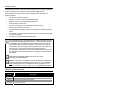
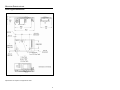
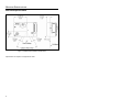
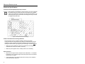
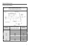
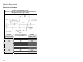
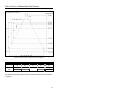
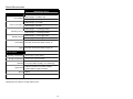
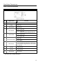
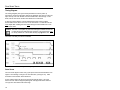
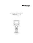
METROLOGIC INSTRUMENTS, INC.
IS4800 microQuest® Series
Single-Line Scanning Engine
Installation Guide
Copyright
© 2005 by Metrologic Instruments, Inc. All rights reserved. No part of this
work may be reproduced, transmitted, or stored in any form or by any means
without prior written consent, except by reviewer, who may quote brief
passages in a review, or provided for in the Copyright Act of 1976.
Products and brand names mentioned in this document are trademarks of
their respective companies.
TABLE OF CONTENTS
Introduction
Models and Accessories ...................................................................................... 1
Components of the microQuest........................................................................ 2
Labels............................................................................................................... 2
Mounting Specifications
Scan Engine Dimensions ................................................................................. 3
Exit Beam Specifications .................................................................................. 4
Enclosure Specifications
Grounding..................................................................................................... 5
Magnetic Sensitivity...................................................................................... 5
Electrostatic Discharge (ESD) Cautions ....................................................... 5
Printed Circuit Board Component Clearance................................................ 6
Airborne Contaminants and Foreign Materials ............................................. 6
Beam Clearance........................................................................................... 6
Output Window Properties............................................................................ 7
Output Window Coatings.............................................................................. 8
Output Window Angle................................................................................... 8
Depth of Field vs Minimum Bar Code Element................................................... 11
Design Specifications ......................................................................................... 12
Scan Engine Terminations
IS4813 Pinout Connections ............................................................................ 14
IS4815 Pinout Connections ............................................................................ 15
Scan Sense Timing
Timing Diagram .............................................................................................. 16
Scan Sense .................................................................................................... 16
Barcode Element Time Calculation ................................................................ 17
Laser and Product Safety
Regulatory Requirements............................................................................... 18
Europe............................................................................................................ 19
United States.................................................................................................. 20
ii
TABLE OF CONTENTS
Canada........................................................................................................... 21
Cautions ......................................................................................................... 22
Limited Warranty ................................................................................................ 23
Patents ............................................................................................................... 24
Index .................................................................................................................. 25
Contact Information and Office Locations........................................................... 27
iii
INTRODUCTION
The IS4800 microQuest® series are miniature single-line scan engines designed
for direct integration into customer decode-equipped OEM devices.
The microQuest non-decode scan engine is equipped with a multitude of
features including:
•
•
•
•
•
•
•
•
•
100 Scans per Second, Typical.
Support for 3.3VDC Input Voltage (IS4813 Model)
Support for 5VDC Input Voltage (IS4815 Model)
A 650 nm Bright Laser Diode
A narrow exit angle to provide precision beam positioning.
Automatic (Hardware) Scan Sense
A rugged industry standard size die cast chassis with threaded mounting
holes.
A 10-pin ZIF Connector Industry Standard Pinout for Seamless Integration
into Portable Devices
Low Mass (11 grams) Industry Standard Size
The manufacturer of the end equipment must register with agencies such
as the Food and Drug Administration (FDA). The specifications required
for registration are not obtainable until the OEM manufacturer uses the
microQuest Engine in its final configuration. Therefore, it becomes the
responsibility of the manufacturer who incorporates the scan engine into
their product to comply with all federal laser safety regulations.
The manufacturer must submit a Laser Product Report for the FDA in the
US. Metrologic will assist its customers in complying with the necessary
procedures.
THIS DEVICE DOES NOT COMPLY WITH 21 CFR 1040.
USE ONLY AS COMPONENT.
Caution: The laser is susceptible to permanent damage if enabled less
than 50 ms after the Scan Enable has been activated. This requirement
must be strictly adhered to or the limited warranty on page 23 is void.
Refer to Scan Sense Timing on pages 16 - 17 for additional information.
MODELS AND ACCESSORIES
Model
Description
IS4813
Non-Decode, 3.3VDC Scan Engine
IS4815
Non-Decode, 5VDC Scan Engine
19-07335
10-pin Flex Cable
1
COMPONENTS OF THE MICROQUEST
Figure 1. IS4800 Series Components
ITEM NO.
DESCRIPTION
Pin Locator Holes (specifications on page 3)
Threaded Mounting Points (specifications on page 3)
Exit Beam Location, Laser Light Aperture
AVOID EXPOSURE – LASER LIGHT
IS EMITTED FROM THIS APERTURE
Die Cast Chassis
10-Pin ZIF Connector
Printed Circuit Board
LABELS
The serial number/model number label is located on engine chassis (see below).
Figure 2. Serial Number Label (Enlarged For Illustration Purposes)
2
MOUNTING SPECIFICATIONS
Scan Engine Dimensions
Figure 3. IS4800 Series Dimensions
Specifications are subject to change without notice.
3
MOUNTING SPECIFICATIONS
Exit Beam Specifications
Figure 4. IS4800 Series Exit Beam Specifications
Specifications are subject to change without notice.
4
MOUNTING SPECIFICATIONS
Enclosure Specifications
The IS4800 scan engine series was specifically designed for integration into
custom housings for OEM applications. The scan engine’s performance will be
adversely affected or permanently damaged when mounted in an unsuitable
enclosure.
THIS DEVICE DOES NOT COMPLY WITH 21 CFR 1040.
USE ONLY AS COMPONENT.
The limited warranty (on page 23) is void if the following
considerations are not adhered to when integrating the
IS4800 series scan engine into a system.
Grounding
If the scan engine is going to be installed in a grounded host:
•
Use an insulator between the engine chassis and host. The die-cast
engine chassis is at +Vcc.
•
Use shoulder washers to isolate the screws from the host if the mounting
screws are metallic.
Magnetic Sensitivity
The scan engine can be negatively affected by magnetic fields:
•
Use only non-magnetic screws and locating pins.
•
Do not mount the engine within 1.00" of any magnetic materials.
Electrostatic Discharge (ESD) Cautions
The scan engine has exposed electrical components.
•
DO NOT touch the leads of the Visible Laser Diode (VLD) or other
components.
•
ALWAYS use grounding wrist straps and a grounded work area when
handling the engine.
•
Mount the engine in a housing that is designed for ESD protection and
stray electric fields.
ESD has the ability to modify the electrical characteristics of a
semiconductor device, possibly degrading or even destroying the
device. ESD also has the potential to upset the normal operation
of an electronic system, causing equipment malfunction or failure.
5
MOUNTING SPECIFICATIONS
Enclosure Specifications
Printed Circuit Board (PCB) Component Clearance
WARNING: When designing the IS4800 into the final product, be sure to eliminate
all possible means of shorting Resistors R3 and R25 in the IS4800.
A short could enable the scan engine to emit Class 3R radiation. Any
CDRH filing will require a disclosure of the design ensuring a method
to mitigate a potential short.
Figure 5. IS4800 PCB Clearence Warning
Airborne Contaminants and Foreign Materials
The scan engine has very sensitive miniature electrical and optical
components that must be protected from airborne contaminants and foreign
materials. In order to prevent permanently damaging the scan engine and
voiding the limited warranty (on page 23), the scan engine enclosure must be:
•
Sealed to prevent infiltration by airborne contaminants and foreign
materials such as dust, dirt, smoke, and smog.
•
Sealed to protect against water, humidity and be non-condensing.
Beam Clearance
6
•
Keep the scan engine’s beam sweep free from obstructions. For detailed
information on the exit beam angle and location please refer to Exit Beam
Specifications on page 4.
•
A dark matte-finish on the internal walls of the housing can be utilized to
avoid internal beam reflections.
MOUNTING SPECIFICATIONS
Enclosure Specifications
Output Window Properties
Please contact a Metrologic representative to coordinate the best
window material required to maintain laser safety requirements for
your application.
An improperly placed window has the potential to seriously reduce
the scan engine’s performance. Careful consideration must be made
when designing the output window’s distance and angle placement
relative to the scan engine’s exit beam and chassis.
Follow these guidelines when designing the output window.
•
Acceptable window materials include; Acrylic (cast or molded), float glass,
CR-39, and Polycarbonate.
Molded polycarbonate is high in strength but might exhibit a
phenomenon called birefringence. Birefringence refers to multiple
indices of refraction within one material. This condition will induce
polarization effects that can be detrimental to scan performance of
the engine. Check with a Metrologic representative before utilizing
a transparent polycarbonate material for the output window.
•
The exit window material should have a spectral transmission of at least
85% from 640 nm to 690 nm and should block shorter wavelengths.
•
Red cell-cast acrylic is recommended.
•
The exit window should exhibit a wavefront distortion (transmission) of no
more than 0.2 wavelengths peak-to-valley maximum over any 0.08"
diameter within the clear aperture.
•
The clear aperture of the output window should extend beyond the 54°
beam sweep (see Exit Beam Specifications on page 4).
•
It should have a 60-40 surface quality and be optically flat, clear, free of
scratches, pits, or seeds. If possible recess the window into the housing for
protection or apply a scratch resistance coating (see Output Window
Coatings on page 8).
•
Apply an anti-reflective coating to the window surfaces to reduce the
possibility of reflective light interfering with the engine’s performance due to
the window angle (see Output Window Coatings on page 8).
7
MOUNTING SPECIFICATIONS
Enclosure Specifications
Output Window Coatings
•
Anti-Reflection
An anti-reflective coating can be applied to the inside and/or outside of the
window to reduce the possibility of internal beam reflections interfering with
the scan performance of the engine. If an anti-reflective coating is applied
it is recommended that it be on both sides of the window providing a 0.5%
maximum reflectivity on each side from 640 to 690 namometers at the
nominal window tilt angle. The coating must also meet the hardness
adherence requirements of MIL-M-13508.
•
Polysiloxane Coating
Applying a polysiloxane coating to the window surface can help protect the
window from surface scratches and abrasions that may interfere with the
scan performance of the engine. Recessing the window into the housing
can also provided added protection against surface damage such as
scratches and chips. If an anti-reflective coating is used, there is no need
to apply a polysiloxane coating.
Output Window Angle
An improperly placed window has the potential to seriously reduce the
scan engine’s performance. Careful consideration must be made
when designing the output window’s distance and angle placement
relative to the scan engine’s exit beam and chassis.
It is important that angle of the window not be perpendicular to the exit beam
of the scan engine. The angle of the window can cause the beam’s laser
light to reflect off the inside of the window back into the scan engine’s optics
ultimately degrading the engine’s performance.
Please refer to the figures on page 9 and page 10 for specifications on the
minimum allowable window angle required to avoid reflective beam
interference.
8
MOUNTING SPECIFICATIONS
Enclosure Specifications
Minimum Allowable Window Position
Required To Avoid Detrimental Internal Reflective Beam Interference
at Positive Exit Beam Angle Tolerance
Figure 6.
Minimum Projected Distance
from the Engine’s Base to the
Window’s Internal Surface (L)
Minimum
Window Angle θ
+2.5°
5.0
28.0°
+2.5°
10.0
14.5°
+2.5°
15.0
10.5°
+2.5°
20.0
8.0°
+2.5°
25.0
7.0°
+2.5°
30.0
6.5°
+2.5°
35.0
6.0°
+2.5°
40.0
5.5°
+2.5°
45.0
5.0°
+2.5°
50.0
5.0°
Exit Beam
Elevation Angle α
Specifications are subject to change without notice.
9
MOUNTING SPECIFICATIONS
Enclosure Specifications
Minimum Allowable Window Position
Required To Avoid Detrimental Internal Reflective Beam Interference
at Negative Exit Beam Angle Tolerance
Figure 7.
Exit Beam
Depression Angle β
Minimum Projected Distance
from the Engine’s Base to the
Window’s Internal Surface (M)
Minimum
Window Angle θ
-2.5°
5.0
23.5°
-2.5°
10.0
16.5°
-2.5°
15.0
12.5°
-2.5°
20.0
10.5°
-2.5°
25.0
9.0°
-2.5°
30.0
8.0°
-2.5°
35.0
7.5°
-2.5°
40.0
7.0°
-2.5°
45.0
6.5°
-2.5°
50.0
6.0°
Specifications are subject to change without notice.
10
DEPTH OF FIELD VS MINIMUM BAR CODE ELEMENT
Figure 8. Depth of Field vs Minimum Bar Code Element
MINIMUM BAR CODE ELEMENT WIDTH
A
B
C
D
E
mm
.13
.19
.26
.33
.49
mils
5.2
7.5
10.4
13
19.5
For additional information please refer to the Barcode Element Time Calculation
on page 17.
11
DESIGN SPECIFICATIONS
IS4800 Series Engine
Operational
Light Source:
Visible Laser Diode (VLD) @ 650 nm
Laser Power:
1 mW
Depth of Scan Field:
50 mm – 254 mm (2" – 10") for
0.33 mm (13 mil) bar codes
Width of Scan Field:
74 mm (2.9") @ 50 mm (2.0");
290 mm (11.4") @ 254 mm (10.0")
Scan Speed:
Scan Pattern:
Minimum Bar Width:
Print Contrast:
Number Characters Read:
Roll, Pitch, Yaw
100 Scan Lines per Second Typical
Single Scan Line
0.127 mm (5.0 mil)
35% Minimum Reflectance Difference
Decode Dependent
42°, 68°, 52°
Mechanical
Dimensions (maximum):
Weight (maximum):
Termination:
24.7 mm x 14.6 mm x 11.9 mm
(.97" x 0.57" x 0.47")
11 g (0.39 oz)
10-pin ZIF Connector
Mounting:
2 Mounting Points,
M1.6 mm Threaded, 2 mm Maximum Depth
Locators:
2 Locating Points,
0.8 mm Diameter, 1.0 mm Depth
Specifications are subject to change without notice.
12
DESIGN SPECIFICATIONS
IS4800 Engine Series
Electrical
Input Voltage:
IS4813 Engine 3.3VDC ± 10%
IS4815 Engine 5.0VDC ± 5%
IS4813 Engine 412.5 mW
Power Consumption:
Operating Current:
Standby Current:
IS4815 Engine 500 mW
IS4813 Engine < 125 mA @ 3.3VDC
IS4815 Engine < 100 mA @ 5.0VDC
IS4813 Engine < 20 mA @ 3.3VDC
IS4815 Engine < 10 mA @ 5.0VDC
Laser Class:
See Laser and Product Safety on page 18
EMC:
See Laser and Product Safety on page 18
Environmental
Operating Temperature:
Storage Temperature:
Humidity:
Light Levels:
Shock:
-20°C to 50°C (-4°F to 122°F)
-40°C to 70°C (-40°F to 158°F)
5% to 95% relative humidity, non-condensing
Sunlight: 107,000 Lux (10,000 ft-candles)
Ambient: 4842 Lux (450 ft-candles)
2000 G
Specifications are subject to change without notice.
13
SCAN ENGINE TERMINATIONS
IS4813 Pinout Connections
IS4813 10-Pin ZIF
Figure 9. 10-Pin ZIF
Pin
Signal Name
Function
1
No Connect
No Connect
2
Power
3.3V ± 10%
3
No Connect
No Connect
High = Laser OFF
4
Laser Enable*
5
Scan Enable*
6
Digitized Bar Pattern
7
Start of Scan
8
Ground
Power Ground
9
Ground
Power Ground
10
No Connect
*
14
Low = Laser ON,
only if pin 5 (scan enable) is also Low
High = Engine OFF
Low = Engine ON
High = Bar
Low = Space
Level changes from high to low, or low to high,
when the laser changes direction at the start of
the scan line.
No Connect
See Scan Sense Timing on page 16.
SCAN ENGINE TERMINATIONS
IS4815 Pinout Connections
IS4815 10-Pin ZIF
Figure 10. 10-Pin ZIF
Pin
Signal Name
Function
1
No Connect
2
Power
3
No Connect
4
Laser Enable*
5
Scan Enable*
6
Digitized Bar Pattern
7
Start of Scan
8
Ground
Power Ground
9
Ground
Power Ground
10
No Connect
No Connect
5.0V ± 5%
No Connect
High = Laser OFF
Low = Laser ON,
only if pin 5 (scan enable) is also Low
High = Engine OFF
Low = Engine ON
High = Bar
*
Low = Space
Level changes from high to low, or low to high,
when the laser changes direction at the start of
the scan line.
No Connect
See Scan Sense Timing on page 16.
15
SCAN SENSE TIMING
Timing Diagram
The Timing Diagram (see Figure below) illustrates the correct power up
procedure to ensure that the laser diode is not damaged upon start up of the unit.
Upon start up, both scan Enable and Laser Enable are to be held high. In this
state, both the scan mirror and the laser diode are not functional.
A minimum of 2ms after the unit has obtained the proper working voltage;
Scan Enable can be driven low to turn on the scan mirror. A minimum of 50 ms
must elapse after enabling the scan before driving the Laser Enable low to turn
on the laser diode.
Caution: The laser is susceptible to permanent damage if enabled less than 50
ms after the Scan Enable has been activated. This requirement must
be strictly adhered to or the limited warranty on page 23 is void.
The unit is now ready to scan bar code data.
Figure 11. Timing Diagram
Scan Sense
The scan sense signal is a 50% duty cycle square wave with the transitions from
High to Low indicating a change in the scan direction, (see Figure 10). Valid
scan data occurs between these transitions.
If scan enable is High (off) the scan sense signal will stay High. If for some
reason the scan mirror is stopped (damage for example) when Scan enable is
Low (on) then Scan Sense will remain High.
16
SCAN SENSE TIMING
Barcode Element Time Calculation
Realization of the full depth of field for all barcodes given in the specification is
based on the ability of the decoding hardware to resolve a varying range of
minimum element times. The minimum element time calculation for a given
barcode size at a given distance is shown in Equation 1(below).
Minimum Element Time = (Element Size / Spot Speed)
Equation 1.
Example:
Barcode Size = 5.2 mil
Spot Speed @ 95 mm from face = 650 inches/second
Minimum Element Time = (0.0052 inches/ (650 inches/second)) = 8.0 µsec
17
LASER AND PRODUCT SAFETY
Regulatory Requirements
THIS DEVICE DOES NOT COMPLY WITH 21 CFR 1040.
USE ONLY AS COMPONENT.
The IS4800 Series microQuest Laser Scan engines are designed to
meet the requirements of IEC Class 2 in accordance with
IEC 60825-1:1993+A1:1997+A2:2001. IEC Class 2 is defined as follows:
Emission Duration:
Accessible Emission Limit:
Greater than 0.25 seconds
Less than 0.001 W (1.0 milliwatts)
average radiant power
The IS4800 series laser scan engine is registered with the Center for Devices
and Radiological Health as a laser “component”. The addition of shut-down
controls, labeling and informational requirements are necessary to achieve
compliance with the performance standard published in the Code of Federal
Regulations (CFR), Title 21 Parts 1040.10 and 1040.11. Therefore, it is the
responsibility of the manufacturer who incorporates the scan engine into
their product to provide the additional performance, labeling and
informational requirements necessary to comply with all federal laser
safety regulations.
The specifications required for agency approval are not obtainable until the
microQuest engine is used in its final configuration. Metrologic is unable to fulfill
these requirements because the scan engine will operate differently depending
upon where it is used as a component. The following information concerning the
scan engine appears on the shipping label:
THIS DEVICE DOES NOT COMPLY WITH 21 CFR 1040.
USE ONLY AS A COMPONENT.
Manufacturers incorporating unmodified microQuest engines into their product
may reference the following accession number on items in their Laser Product
Report that request information concerning features inherent in the microQuest
engine design.
Accession Number: Pending
If the product is to be used in another country, it is the responsibility of the
manufacturer who incorporates the scan engine into their product to fulfill
any regulatory compliance requirements for that country. Refer to one of the
following sections for further explanation.
18
LASER AND PRODUCT SAFETY
Europe
The CE Mark is required on products which incorporate the IS4813 and the
IS4815 scan engines if the products are to be imported into European
Economic Area (EEA) countries. Use of the CE Mark requires compliance with
directives and standards dependent upon the type of product. Information may
be found at http://europa.eu.int/comm/enterprise/newapproach/.
Laser Safety
IEC 60825-1:1993+A1:1997+A2:2001,
EN 60825-1:1994+A2:2001+A1:2002
“Safety of Laser products”
Compliance with either of the standards listed above is required for the product
to bear the CE mark.
Note:
Non EEA countries may impose additional testing/certification
requirements.
EMC
Certain combinations of microQuest scan engines and associated electronics
may require certification of compliance with the European EMC Directive.
EMC compliance of finished products in Europe can be accomplished by the
following method:
•
The manufacturer may certify to the EC’s Electromagnetic Compatibility
Directive 89/336/EEC. Compliance is required for the product to bear the
CE Mark.
Note:
Non EEA countries may impose additional testing/certification
requirements.
Electrical Safety
The scan engines are built to conform to the European Low Voltage
Directive 73/23/ EEC.
19
LASER AND PRODUCT SAFETY
United States
Laser Safety
To assist with the FDA filing requirements (refer to Regulatory Requirements),
Metrologic has registered the scan engine with the FDA as a component.
Customers can contact CDRH at the following address:
Food and Drug Administration
Center for Devices and Radiological Health
Light Products Branch (HFX-312)
Office of Compliance
2098 Gaither Road
Rockville, MD 20850
Tel: 301-594-4654
www.fda.gov/cdrh
Requirements for laser products are described in CFR (Code of Federal
Regulation) Title 21, part 1040.10 & 1040.11 from the Government Printing
Office. Copies can be ordered by calling 202-512-1800, ordering on line from
www.access.gpo.gov or writing to:
Superintendent of Documents
PO Box 371954
Pittsburgh, PA 15250-7954
Note:
State and local governments may regulate the use products containing
lasers. The manufacturer should consult the applicable government
regulations for more information.
Copies of Product Reporting Guides, other guides, and related documents
are available as PDF documents from the CDRH website at:
www.fda.gov/cdrh/comp/eprc.html. Additional resources include the Division of
Small Manufacturers, International and Consumer Assistance (DSMICA) in
Rockville, Maryland at 1-800-638-2041.
EMC
Certain combinations of scan engines and associated electronics may require
testing to insure compliance with the following Federal Communications
Commission regulation: 47 CFR Part 15
Note:
20
When using the scan engine with RF equipment, modems, etc. may
require examination(s) to the standard(s) for the specific equipment
combination. It is the manufacturers’ responsibility to comply with the
applicable federal regulation(s).
LASER AND PRODUCT SAFETY
Canada
Laser Safety
The Radiation Protection Bureau currently accepts products meeting the FDA
standards in Canada. For more information contact:
Radiation Protection Bureau
775 Brookfield Road
Ottawa, Ontario K1A 1C1
EMC
Products meeting FCC 47 CFR Part 15 will meet Industry Canada
interference-causing equipment standard for digital apparatus, ICES-003.
Additional testing is not required.
A written notice indicating compliance must accompany the apparatus to the
end user. The notice shall be in the form of a label that is affixed to the
apparatus. The notice may be in the form of a statement included in the user’s
manual if, because of insufficient space or other restrictions, it is not feasible to
affix a label to the apparatus.
21
LASER AND PRODUCT SAFETY
Cautions
Caution
Use of controls or adjustments or performance of procedures other than those specified
herein may result in hazardous laser light exposure. Under no circumstances should the
customer attempt to service the laser scanner. Never attempt to look at the laser beam, even
if the scanner appears to be nonfunctional. Never open the scanner in an attempt to look
into the device. Doing so could result in hazardous laser light exposure. The use of optical
instruments with the laser equipment will increase eye hazard.
Atención
La modificación de los procedimientos, o la utilización de controles o ajustes distintos de
los especificados aquí, pueden provocar una luz de láser peligrosa. Bajo ninguna
circunstancia el usuario deberá realizar el mantenimiento del láser del escáner. Ni intentar
mirar al haz del láser incluso cuando este no esté operativo. Tampoco deberá abrir el
escáner para examinar el aparato. El hacerlo puede conllevar una exposición peligrosa a la
luz de láser. El uso de instrumentos ópticos con el equipo láser puede incrementar el
riesgo para la vista.
Attention
L'emploi de commandes, réglages ou procédés autres que ceux décrits ici peut entraîner
de graves irradiations. Le client ne doit en aucun cas essayer d'entretenir lui-même le
scanner ou le laser. Ne regardez jamais directement le rayon laser, même si vous croyez
que le scanner est inactif. N'ouvrez jamais le scanner pour regarder dans l'appareil. Ce
faisant, vous vous exposez à une rayonnement laser qú êst hazardous. L'emploi
d'appareils optiques avec cet équipement laser augmente le risque d'endommagement de
la vision.
Achtung
Die Verwendung anderer als der hier beschriebenen Steuerungen, Einstellungen oder
Verfahren kann eine gefährliche Laserstrahlung hervorrufen. Der Kunde sollte unter keinen
Umständen versuchen, den Laser-Scanner selbst zu warten. Sehen Sie niemals in den
Laserstrahl, selbst wenn Sie glauben, daß der Scanner nicht aktiv ist. Öffnen Sie niemals
den Scanner, um in das Gerät hineinzusehen. Wenn Sie dies tun, können Sie sich einer
gefährlichen Laserstrahlung aussetzen. Der Einsatz optischer Geräte mit dieser
Laserausrüstung erhöht das Risiko einer Sehschädigung.
Attenzione
L’utilizzo di sistemi di controllo, di regolazioni o di procedimenti diversi da quelli descritti nel
presente Manuale può provocare delle esposizioni a raggi laser rischiose. Il cliente non
deve assolutamente tentare di riparare egli stesso lo scanner laser. Non guardate mai il
raggio laser, anche se credete che lo scanner non sia attivo. Non aprite mai lo scanner per
guardare dentro l’apparecchio. Facendolo potete esporVi ad una esposizione laser
rischiosa. L’uso di apparecchi ottici, equipaggiati con raggi laser, aumenta il rischio di
danni alla vista.
22
LIMITED WARRANTY
The IS4800 microQuest® series scan engines are manufactured by Metrologic at its Blackwood, New
Jersey, USA facility and its Suzhou, China facility. The microQuest scan engines have a two (2) year
limited warranty from the date of manufacture. Metrologic warrants and represents that all microQuest
scan engines are free of all defects in material, workmanship and design, and have been produced and
labeled in compliance with all applicable US Federal, state and local laws, regulations and ordinances
pertaining to their production and labeling.
This warranty is limited to repair, replacement of product or refund of product price at the sole discretion
of Metrologic. Faulty equipment must be returned to one of the following Metrologic repair facilities:
Blackwood, New Jersey, USA; Madrid, Spain; or Suzhou, China. To do this, contact the appropriate
Metrologic Customer Service/Repair Department to obtain a Returned Material Authorization (RMA)
number.
In the event that it is determined that the equipment failure is covered under the warranty, Metrologic
shall, at its sole option, repair the Product or replace the Product with a functionally equivalent unit
and return such repaired or replaced Product without charge for service or return freight, whether
distributor, dealer/reseller, or retail consumer, or refund an amount equal to the original purchase
price.
This limited warranty does not extend to any Product which, in the sole judgment of Metrologic, has
been subjected to abuse, misuse, neglect, improper installation or handling or is damaged as a result
of a failure to follow instructions contained in this manual or other documentation provided with the
Product. The warranty is void if the Product is not encased in a properly designed enclosure (sealed
to: (a) prevent infiltration by airborne contaminants; (b) protect against ESD, humidity and mechanical
shocks; and (c) be non-condensing) or Product is opened by anyone other than Metrologic’s repair
department or authorized repair centers. For additional information on enclosure design, see
pages 5 -10 of the Installation Guide.
THIS LIMITED WARRANTY, EXCEPT AS TO TITLE, IS IN LIEU OF ALL OTHER W A R R A N T I E S OR
G U A R A N T E E S , EITHER E X P R E S S OR IMPLIED, AND S P E C I F I C A L L Y EXCLUDES,
W I T H O U T L I M I T A T I O N , W A R R A N T I E S OF MERCHANTABILITY AND FITNESS FOR A
PARTICULAR PURPOSE UNDER THE UNIFORM COMMERCIAL CODE, OR ARISING OUT OF CUSTOM
OR CONDUCT. THE RIGHTS AND REMEDIES PROVIDED HEREIN ARE EXCLUSIVE AND IN LIEU OF
ANY OTHER RIGHTS OR REMEDIES. IN NO EVENT SHALL METROLOGIC BE LIABLE FOR ANY
INDIRECT OR CONSEQUENTIAL DAMAGES, INCIDENTAL DAMAGE, DAMAGES TO PERSON OR
PROPERTY, OR EFFECT ON BUSINESS OR PROPERTY, OR OTHER DAMAGES OR EXPENSES DUE
DIRECTLY OR INDIRECTLY TO THE PRODUCT, EXCEPT AS STATED IN THIS WARRANTY. IN NO
EVENT SHALL ANY LIABILITY OF METROLOGIC EXCEED THE ACTUAL AMOUNT PAID TO
METROLOGIC FOR THE PRODUCT. METROLOGIC RESERVES THE RIGHT TO MAKE ANY CHANGES
TO THE PRODUCT DESCRIBED HEREIN.
WORLDWIDE HEADQUARTERS,
Metrologic Instruments, Inc.
90 Coles Rd.
Blackwood, NJ 08012-4683
Tel: 856-228-8100
Fax: 856-228-6673
Email: [email protected]
METROLOGIC THE AMERICAS HEADQUARTERS
METROLOGIC THE AMERICAS
1571 Imperial Way Suite B
West Deptford, NJ 08066
Tel: 800-ID-METRO (800-436-3876)
Fax: 856-537-6474
Email: [email protected]
MTLG AUTO ID INSTRUMENTS (SHANGHAI) CO., LTD
Suzhou Sales Office
BLK A, Room# 03/03-04
No.5 Xinghan Street, Xinsu Industrial Square
China-Singapore
Suahou Industrial Park, Suzhou, PRC
Tel: 86-512-67622550
Fax: 86-512-67622560
Email: [email protected]
METROLOGIC EUROPEAN REPAIR CENTER (MERC)
Metrologic Eria Ibérica, SL
Julian Camarillo 29, D-1
28037 Madrid
Tel: +34 913 272 400
Fax: +34 913 273 829
Email: [email protected]
23
PATENTS
Worldwide patents pending.
24
INDEX
A
F
Accessories ...................................1
Aperture.........................................2
Assignments
pin .................................. 2, 14, 15
Faulty equipment ........................ 23
FDA....................................... 20, 21
B
Ground .............................. 5, 14, 15
Beam
aperture .....................................4
clearance ...................................5
exit angle ...........................1, 4, 8
exit location................................2
specifications .............................4
I
C
L
Cable
flex .........................................1, 2
Caution ........................................22
CDRH ........................ 13, 18, 19, 20
CE ...............................................22
CMOS....................................14, 15
Compliance ..................... 19, 20, 21
Connector
10-Pin ZIF ...................... 2, 14, 15
pin assignments.................14, 15
Current ........................................13
operating..................................13
standby ....................................13
Customer Service........................23
Label ............................................. 2
Laser
aperture ..................................... 2
beam ..................................... 2, 5
class ........................................ 13
enable................................ 14, 15
power ...................................... 12
safety................. 1, 18, 19, 20, 21
VLD ........................................... 5
Light Source................................ 12
Limited warranty.......................... 23
Location Pins .......................... 2, 12
D
Depth of Field ........................11, 12
Design
specifications .....................12, 13
Dimensions..................................12
E
Electrical
safety .................................13, 19
Electrostatic Discharge..................5
EMC ................................ 19, 20, 21
Enclosure ......................................5
G
Indicators
beam ................................. 18, 19
IS4813 .............................. 1, 13, 14
IS4815 .............................. 1, 13, 15
M
Magnetic Sensitivity ...................... 5
Mounting ....................................... 2
N
Non-Decode.................................. 1
O
OEM.............................................. 1
P
Pin..................................... 2, 14, 15
Power.................................... 14, 15
25
INDEX
R
U
Regulatory Requirements.....18, 19,
20, 21
Canada Laser Safety ...............21
Europe Laser Safety ................19
United States Laser Safety ......20
Repair..........................................23
RMA ............................................23
UL ............................................... 13
S
Scan
enable ................................14, 15
Scan Field
depth........................................12
width ........................................12
Scan Sense Timing ......... 14, 15, 16
Scan Speed.................................12
Service ........................................23
T
Temperature................................13
Timing Diagram ...........................16
26
V
Voltage........................ 1, 13, 19, 20
W
Warranty ..................................... 23
Watt(s) .................................. 18, 19
Weight..................................... 1, 12
Window
angle ................................... 9–10
coatings ................................. 7, 8
materials.................................... 7
specifications......................... 7, 8
transmission .............................. 7
Z
ZIF .................................. 12, 14, 15
27
November 2005
Printed in USA
00 - 02019B