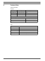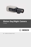
1
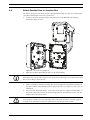
VEI-30 Dinion Infrared Imager
VEI-Series
en
Installation Manual
VEI-30 Dinion Infrared Imager
Table of Contents | en
3
Table of Contents
1
Safety
5
1.1
Safety precautions
5
1.2
Important notices
5
1.3
FCC & ICES compliance
8
1.4
CSA certification
9
1.5
Bosch notices
9
2
Description
10
2.1
Unpacking
10
2.2
Parts List
10
2.2.1
Parts Included with the Product
10
2.2.2
User-supplied Parts
10
3
Planning
11
3.1
Hardware Requirements
11
3.2
Pre-installation Checklist
12
4
Installation
13
4.1
Mount the Junction Box
13
4.2
Route Wires and Attach Connectors
14
4.3
Attach Pendant Arm to Junction Box
15
5
Connection
16
5.1
Power Connection
16
5.2
Video and Control Cables
16
5.3
Alarm Output Connections
17
6
Configuration
18
6.1
Accessing the Controls
18
6.2
Adjusting the Focus and Focal Length
19
6.3
Making Pan Adjustments
20
6.4
Making Tilt Adjustments
20
6.5
Adjusting the Variable Field Illumination
21
6.5.1
Adjusting the LED Tilt Angle
21
6.5.2
Adjusting the Illumination Beam Width
21
Bosch Security Systems, Inc.
Installation Manual
F.01U.166.250 | 1.0 | 2011.04
4
en | Table of Contents
7
VEI-30 Dinion Infrared Imager
Operation
23
7.1
Menus
23
7.1.1
Top level menus
23
7.1.2
Menu navigation
23
7.2
Pre-defined modes
24
7.3
Camera control communication (Bilinx)
24
7.4
Main menu structure
25
7.4.1
Mode submenu
25
7.4.2
ALC submenu
25
7.4.3
Shutter/AGC submenu
26
7.4.4
Day/Night submenu
27
7.4.5
Illuminator submenu
28
7.4.6
Enhance / Dynamic Engine submenu
28
7.4.7
Color submenu
29
7.4.8
VMD submenu
30
7.5
Install menu structure
31
7.5.1
Lens Wizard submenu
31
7.5.2
Language submenu
32
7.5.3
Privacy Masking submenu
32
7.5.4
Synchronization submenu
32
7.5.5
Alarm Output submenu
33
7.5.6
Connections submenu
33
7.5.7
Test Signals submenu
33
7.5.8
Camera ID submenu
34
7.5.9
Defaults submenu
34
8
Maintenance
35
8.1
Repairs
35
8.2
Transfer and Disposal
35
9
Technical Data
36
Index
38
F.01U.166.250 | 1.0 | 2011.04
Installation Manual
Bosch Security Systems, Inc.
VEI-30 Dinion Infrared Imager
Safety | en
1
Safety
1.1
Safety precautions
5
DANGER!
High risk: This symbol indicates an imminently hazardous situation such as “Dangerous
Voltage” inside the product.
If not avoided, this will result in an electrical shock, serious bodily injury, or death.
WARNING!
Medium risk: Indicates a potentially hazardous situation.
If not avoided, this could result in minor or moderate bodily injury.
CAUTION!
Low risk: Indicates a potentially hazardous situation.
If not avoided, this could result in property damage or risk of damage to the unit.
1.2
Important notices
Accessories - Do not place this unit on an unstable stand, tripod, bracket, or mount. The unit
may fall, causing serious injury and/or serious damage to the unit. Use only with the cart,
stand, tripod, bracket, or table specified by the manufacturer. When a cart is used, use
caution and care when moving the cart/apparatus combination to avoid injury from tip-over.
Quick stops, excessive force, or uneven surfaces may cause the cart/unit combination to
overturn. Mount the unit per the manufacturer's instructions.
All-pole power switch - Incorporate an all-pole power switch, with a contact separation of at
least 3 mm in each pole, into the electrical installation of the building. If it is needed to open
the housing for servicing and/or other activities, use this all-pole switch as the main
disconnect device for switching off the voltage to the unit.
Camera grounding - For mounting the camera in potentially damp environments, ensure to
ground the system using the ground connection of the power supply connector (see section:
Connecting external power supply).
Camera lens - An assembled camera lens in the outdoor housing must comply and be tested
in accordance with UL/IEC60950. Any output or signal lines from the camera must be SELV or
Limited Power Source. For safety reasons the environmental specification of the camera lens
assembly must be within the environmental specification of -10 °C to 50 °C (14 °F to 122 °F).
Camera signal - Protect the cable with a primary protector if the camera signal is beyond 140
feet, in accordance with NEC800 (CEC Section 60).
CAUTION!
CLASS 1 LED PRODUCT
IEC60825-1 Ed. 1.2 (2001)
Bosch Security Systems, Inc.
Installation Manual
F.01U.166.250 | 1.0 | 2011.04
6
en | Safety
VEI-30 Dinion Infrared Imager
Coax grounding:
–
–
Ground the cable system if connecting an outside cable system to the unit.
Connect outdoor equipment to the unit's inputs only after this unit has had its grounding
plug connected to a grounded outlet or its ground terminal is properly connected to a
ground source.
–
Disconnect the unit's input connectors from outdoor equipment before disconnecting
the grounding plug or grounding terminal.
–
Follow proper safety precautions such as grounding for any outdoor device connected to
this unit.
U.S.A. models only - Section 810 of the National Electrical Code, ANSI/NFPA No.70, provides
information regarding proper grounding of the mount and supporting structure, grounding of
the coax to a discharge unit, size of grounding conductors, location of discharge unit,
connection to grounding electrodes, and requirements for the grounding electrode.
Disposal - Your Bosch product was developed and manufactured with high-quality material
and components that can be recycled and reused. This symbol means that electronic and
electrical appliances, which have reached the end of their working life, must be collected and
disposed of separately from household waste material. Separate collecting systems are
usually in place for disused electronic and electrical products. Please dispose of these units
at an environmentally compatible recycling facility, per European Directive 2002/96/EC.
Electronic Surveillance - This device is intended for use in public areas only. U.S. federal law
strictly prohibits surreptitious recording of oral communications.
Environmental statement - Bosch has a strong commitment towards the environment. This
unit has been designed to respect the environment as much as possible.
Electrostatic-sensitive device - Use proper CMOS/MOS-FET handling precautions to avoid
electrostatic discharge.
NOTE: Wear required grounded wrist straps and observe proper ESD safety precautions when
handling the electrostatic-sensitive printed circuit boards.
Fuse rating - For protection of the device, the branch circuit protection must be secured with
a maximum fuse rating of 16A. This must be in accordance with NEC800 (CEC Section 60).
Grounding and polarization - This unit may be equipped with a polarized alternating current
line plug (a plug with one blade wider than the other blade). This safety feature allows the
plug to fit into the power outlet in only one way. If unable to insert the plug fully into the
outlet, contact a locally certified electrician to replace the obsolete outlet. Do not defeat the
safety purpose of the polarized plug.
Alternately, this unit may be equipped with a 3-pole grounding plug (a plug with a third pin for
earth grounding). This safety feature allows the plug to fit into a grounded power outlet only.
If unable to insert the plug into the outlet, contact a locally certified electrician to replace the
obsolete outlet. Do not defeat the safety purpose of the grounding plug.
Moving - Disconnect the power before moving the unit. Move the unit with care. Excessive
force or shock may damage the unit and the hard disk drives.
Outdoor signals - The installation for outdoor signals, especially regarding clearance from
power and lightning conductors and transient protection, must be in accordance with NEC725
and NEC800 (CEC Rule 16-224 and CEC Section 60).
Permanently connected equipment - Incorporate a readily accessible disconnect device
external to the equipment.
Pluggable equipment - Install the socket outlet near the equipment so it is easily accessible.
Power resupply - If the unit is forced to power down due to exceeding the specified operating
temperatures, disconnect the power cord, wait for at least 30 seconds, and then reconnect
the power cord.
F.01U.166.250 | 1.0 | 2011.04
Installation Manual
Bosch Security Systems, Inc.
VEI-30 Dinion Infrared Imager
Safety | en
7
Power lines - Do not locate the camera near overhead power lines, power circuits, or
electrical lights, nor where it may contact such power lines, circuits, or lights.
SELV - All the input/output ports are Safety Extra Low Voltage (SELV) circuits. SELV circuits
should only be connected to other SELV circuits.
Because the ISDN circuits are treated like telephone-network voltage, avoid connecting the
SELV circuit to the Telephone Network Voltage (TNV) circuits.
System ground/Safety ground
System (video) ground is indicated by the symbol
Safety (power) ground is indicated by the symbol
.
.
The system ground is only used to comply with safety standards or installation practices in
certain countries. Bosch does not recommend connecting system ground to safety ground
unless it is explicitly required. However, if the system ground and safety ground are
connected and grounding loops are causing interference in the video signal, use an isolation
transformer (available separately from Bosch).
CAUTION!
Connecting System ground to Safety ground may result in ground loops that can disrupt the
CCTV system.
Video loss - Video loss is inherent to digital video recording; therefore, Bosch Security
Systems cannot be held liable for any damage that results from missing video information. To
minimize the risk of lost digital information, Bosch Security Systems recommends multiple,
redundant recording systems, and a procedure to back up all analog and digital information.
Bosch Security Systems, Inc.
Installation Manual
F.01U.166.250 | 1.0 | 2011.04
8
1.3
en | Safety
VEI-30 Dinion Infrared Imager
FCC & ICES compliance
FCC Information
(U.S.A. and Canadian Models Only)
This equipment has been tested and found to comply with the limits for a Class B digital
device, pursuant to part 15 of the FCC Rules. These limits are designed to provide reasonable
protection against harmful interference in a residential installation. This equipment
generates, uses, and can radiate radio frequency energy and, if not installed and used in
accordance with the instructions, may cause harmful interference to radio communications.
However, there is no guarantee that interference will not occur in a particular installation. If
this equipment does cause harmful interference to radio or television reception, which can be
determined by turning the equipment off and on, the user is encouraged to try to correct the
interference by one or more of the following measures:
–
reorient or relocate the receiving antenna;
–
increase the separation between the equipment and receiver;
–
connect the equipment into an outlet on a circuit different from that to which the
receiver is connected;
–
consult the dealer or an experienced radio/TV technician for help.
Intentional or unintentional modifications, not expressly approved by the party responsible
for compliance, shall not be made. Any such modifications could void the user's authority to
operate the equipment. If necessary, the user should consult the dealer or an experienced
radio/television technician for corrective action.
The user may find the following booklet, prepared by the Federal Communications
Commission, helpful: How to Identify and Resolve Radio-TV Interference Problems. This booklet
is available from the U.S. Government Printing Office, Washington, DC 20402, Stock No. 004000-00345-4.
Informations FCC et ICES
(modèles utilisés aux États-Unis et au Canada uniquement)
Suite à différents tests, cet appareil s'est révélé conforme aux exigences imposées aux
appareils numériques de classe B, en vertu de la section 15 du règlement de la Commission
fédérale des communications des États-Unis (FCC), et en vertu de la norme ICES-003 d'Industrie
Canada. Ces exigences visent à fournir une protection raisonnable contre les interférences
nuisibles lorsque l'appareil est utilisé dans le cadre d'une installation résidentielle. Cet
appareil génère, utilise et émet de l'énergie de radiofréquences et peut, en cas d'installation
ou d'utilisation non conforme aux instructions, engendrer des interférences nuisibles au
niveau des radiocommunications. Toutefois, rien ne garantit l'absence d'interférences dans
une installation particulière. Il est possible de déterminer la production d'interférences en
mettant l'appareil successivement hors et sous tension, tout en contrôlant la réception radio
ou télévision. L'utilisateur peut parvenir à éliminer les interférences éventuelles en prenant
une ou plusieurs des mesures suivantes:
–
Modifier l'orientation ou l'emplacement de l'antenne réceptrice;
–
Éloigner l'appareil du récepteur;
–
Brancher l'appareil sur une prise située sur un circuit différent de celui du récepteur;
–
Consulter le revendeur ou un technicien qualifié en radio/télévision pour obtenir de
l'aide.
Toute modification apportée au produit, non expressément approuvée par la partie
responsable de l'appareil, est strictement interdite. Une telle modification est susceptible
d'entraîner la révocation du droit d'utilisation de l'appareil.
La brochure suivante, publiée par la Commission fédérale des communications (FCC), peut
s'avérer utile : How to Identify and Resolve Radio-TV Interference Problems (Comment identifier
F.01U.166.250 | 1.0 | 2011.04
Installation Manual
Bosch Security Systems, Inc.
VEI-30 Dinion Infrared Imager
Safety | en
9
et résoudre les problèmes d’interférences de radio et de télévision). Cette brochure est
disponible auprès du U.S. Government Printing Office, Washington, DC 20402, États-Unis,
sous la référence n° 004-000-00345-4.
NOTICE!
This is a class B product. In a domestic environment this product may cause radio
interference, in which case the user may be required to take adequate measures.
1.4
CSA certification
Disclaimer
CSA has not tested the performance or reliability of the security or signaling aspects of this
product. CSA has only tested fire, shock and/or casualty hazards as outlined in CSA's
Standard(s) for Safety for Closed Circuit Television Equipment, UL 2044. CSA Certification does
not cover the performance or reliability of the security or signaling aspects of this product.
CSA MAKES NO REPRESENTATIONS, WARRANTIES, OR CERTIFICATIONS WHATSOEVER
REGARDING THE PERFORMANCE OR RELIABILITY OF ANY SECURITY OR SIGNALING RELATED
FUNCTIONS OF THIS PRODUCT.
Disclaimer
CSA has not tested the performance or reliability of the security or signaling aspects of this
product. CSA has only tested fire, shock and/or casualty hazards as outlined in CSA's
Standard(s) for Safety for Information Technology Equipment, UL 60950-1. CSA Certification
does not cover the performance or reliability of the security or signaling aspects of this
product.
CSA MAKES NO REPRESENTATIONS, WARRANTIES, OR CERTIFICATIONS WHATSOEVER
REGARDING THE PERFORMANCE OR RELIABILITY OF ANY SECURITY OR SIGNALINGRELATED FUNCTIONS OF THIS PRODUCT.
1.5
Bosch notices
Copyright
This manual is the intellectual property of Bosch Security Systems and is protected by
copyright. All rights reserved.
Trademarks
All hardware and software product names used in this document are likely to be registered
trademarks and must be treated accordingly.
NOTE:
This manual has been compiled with great care and the information it contains has been
thoroughly verified. The text was complete and correct at the time of printing. The ongoing
development of the products may mean that the content of the user guide can change without
notice. Bosch Security Systems accepts no liability for damage resulting directly or indirectly
from faults, incompleteness or discrepancies between the user guide and the product
described.
More information
For more information, please contact the nearest Bosch Security Systems location or
visitwww.boschsecurity.com
Bosch Security Systems, Inc.
Installation Manual
F.01U.166.250 | 1.0 | 2011.04
10
en | Description
2
VEI-30 Dinion Infrared Imager
Description
The VEI-30 IR Imager is a high-performance, CCD-based day/night analog camera and built-in
infrared illuminator, with outdoor, all-weather housing and bracketry (rated to IP67).
The VEI-30 is easy to install and ready to use, and offers the best solution for demanding
scene conditions. Features include:
2.1
–
True Day/Night performance with switchable IR filter and Auto Photocell switching mode
–
Illuminator with variable field illumination
–
Progressive scan
–
540 TVL resolution
–
Dynamic engine with Smart BLC
–
Privacy masks
–
Bilinx (bi-directional coaxial communication)
–
Wide operating temperature range (–40°C to +50°C / –40°F to +122°F)
–
Six pre-programmed operation modes
–
Adaptive dynamic noise reduction
–
Multiple language on-screen display
Unpacking
This electronic equipment should be unpacked and handled carefully. If an item appears to
have been damaged in shipment, notify the shipper immediately.
Verify that all the parts listed in the Parts List below are included. If any items are missing,
notify your Bosch Security Systems Sales or Customer Service Representative.
The original packing carton is the safest container in which to transport the unit and must be
used if returning the unit for service. Save it for possible future use.
2.2
Parts List
2.2.1
Parts Included with the Product
Quantity Item
2.2.2
1
VEI-30 IR Imager camera
1
Cable-managed pan/tilt bracket
1
Junction box
1
Sunshield
1
3D Diffuser
1
Hex key set (consisting of 1x 5 mm hex key; 1x 4 mm hex key
1
Corner mount kit (optional)
1
Mast mount kit (optional)
1
Quick Install Guide
User-supplied Parts
Quantity Item
4
Lag bolts, 1/4-9 x 2 (M7-0.35 x 50) with 1/2 in. head
4
1/2 in. (12 mm) washers
2
3/4 in. (20 mm) NPS watertight pipe fittings OR
1/2 in. (15 mm) NPS watertight pipe fittings
F.01U.166.250 | 1.0 | 2011.04
Installation Manual
Bosch Security Systems, Inc.
VEI-30 Dinion Infrared Imager
3
Planning | en
11
Planning
CAUTION!
CLASS 1 LED PRODUCT
IEC60825-1 Ed. 1.2 (2001)
WARNING!
IMPORTANT MOUNTING INSTRUCTIONS
This apparatus must be securely attached to the wall in accordance with these installation
instructions. Failure to follow installation instructions may result in injury or death.
CAUTION!
Ensure that the selected location is protected from falling objects, accidental contact with
moving objects, and unintentional interference from personnel. Follow all applicable building
codes.
Select a suitable location that protects the camera from accidental damage, tampering and
environmental conditions exceeding the specifications of the camera.
Follow these mounting guidelines:
1.
Locate the camera such that it cannot be easily interfered with, either intentionally or
accidentally.
2.
Select a smooth, flat mounting surface to ensure proper sealing. The surface must also
support the combined weight of the camera and mounting hardware under all expected
conditions of vibration and temperature. Recommended mounting height is at least 4 m
(13 ft); however, optimal conditions will vary with the specific installation environment.
3.1
Hardware Requirements
Tools Required
–
1x 5 mm (3/16) hex key; 1x 4 mm (5/32) hex key (supplied)
–
Small, straight-blade screwdriver - 2.5 mm (0.1 in.)
–
Socket wrench and 9/16 in. (14 mm) socket
–
Drill and 7/32 in. (5.5mm) drill bit
Hardware Requirements
–
VEI-30 or NEI-30 junction box
–
Four (4) lag bolts, 1/4-9 x 2 (M7-0.35 x 50) with 1/2 in. head (not supplied)
–
Four (4) 1/2 in. (12 mm) washers (not supplied)
–
Two (2) 3/4 in. (20 mm) NPS watertight pipe fittings OR 1/2 in. (15 mm) NPS watertight
pipe fittings (not supplied)
Bosch Security Systems, Inc.
Installation Manual
F.01U.166.250 | 1.0 | 2011.04
12
3.2
en | Planning
VEI-30 Dinion Infrared Imager
Pre-installation Checklist
WARNING!
This installation must be made by a qualified service person and must conform to all local
codes.
WARNING!
CSA Certified / UL Listed CLASS 2 power adaptors must be used in order to comply with
electrical safety standards.
1.
Determine the location and distance for the junction box based on its voltage and current
consumption.
See Section 5 Connection, page 16, for wiring information and distances.
2.
Use only UL-listed liquid tight strain reliefs for conduits to the junction box to ensure that
water cannot enter the box. You must use 3/4 in. (20 mm) NPS watertight conduits and
fittings (to meet NEMA 4X standards).
WARNING!
Power and I/O cabling must be routed separately inside different permanently earthed metal
conduits.
3.
Route all rough wiring including: power, control, video coax, alarms I/O, relay I/O, and
fiber optic cabling. See Section 5 Connection, page 16, for video and control protocol
methods.
WARNING!
Install external interconnecting cables in accordance with NEC, ANSI/NFPA70 (for US
application) and Canadian Electrical Code, Part I, CSA C22.1 (for CAN application) and in
accordance with local country codes for all other countries.
CSA Certified / UL Listed CLASS 2 power adaptors must be used in order to comply with
electrical safety standards.
Branch circuit protection incorporating a 20 A, 2-pole Listed Circuit Breaker or Branch Rated
Fuses are required as part of the building installation. A readily-accessible 2-pole disconnect
device with a contact separation of at least 3 mm must be incorporated.
4.
Select the appropriate mounting kit to use, depending on the location of the VEI-30 / NEI30 Series camera. The camera is intended to be mounted securely to a wall using the
mounting holes in the junction box.
CAUTION!
Select a rigid mounting location to prevent excessive vibration to the camera.
F.01U.166.250 | 1.0 | 2011.04
Installation Manual
Bosch Security Systems, Inc.
VEI-30 Dinion Infrared Imager
4
Installation | en
13
Installation
This chapter details how to mount the VEI-30 / NEI-30 to a wall. Any variations to the
installation procedures are noted.
4.1
Mount the Junction Box
Before mounting the junction box, decide if you should wire the box through the holes in the
bottom or back of the box. If wiring the box through the back, move the two (2) seal plugs to
the bottom through-holes before mounting. This installation must be made by a qualified
service person and must conform to all local codes.
NOTICE!
Use 3/4 in. (20 mm) NPS fittings for the holes on the bottom and back of the box. Use 1/2 in.
(15 mm) NPS fittings for the side holes.
Figure 4.1
Junction Box Wall Mount
WARNING!
The camera has been evaluated for wall mounting using the following hardware secured into a
2 x 4 stud under 1/2 in. drywall:
–
Four (4) Lag bolts, 1/4-9 x 2 (M7-0.35 x 50) with 1/2 in. head
–
Four (4) 1/2 in. (12 mm) flat washers
Bosch Security Systems, Inc.
Installation Manual
F.01U.166.250 | 1.0 | 2011.04
14
en | Installation
VEI-30 Dinion Infrared Imager
1.
Locate a stud in the wall and mark the outside edges of the stud.
2.
Using the wall mount bracket as a template, align the mounting hole with the center of
the stud.
3.
Mark the point on the wall in the center of the hole where the mounting bolt will be
positioned.
4.
Remove the wall mount bracket and drill a pilot hole at the marked point.
5.
Align the wall mount bracket mounting hole with the hole drilled in the wall.
6.
Using a 9/16 in. (14 mm) socket and driver, secure the wall mount bracket by screwing
the 1/4-9 x 2 (M7-0.35 x 50) lag bolt with 1/2 in. (12 mm) washer securely into the stud.
7.
8.
Follow this procedure to attach the three remaining lag bolts.
Attach 3/4 in. (20 mm) NPS watertight pipe fittings (not supplied) to the bottom or back
holes of the junction box through which you will run the power, video, and control data
wires.
NOTICE!
The camera has not been evaluated for safety requirements using other mounting kits.
4.2
Route Wires and Attach Connectors
Power wires must be routed to the right (front) side of the junction box through a separate
conduit. All video, control, and alarm wires must be routed through a second conduit to the
left side of the box.
WARNING!
External interconnecting cables are to be installed in accordance with NEC, ANSI/NFPA70 (for
US application) and Canadian Electrical Code, Part I, CSA C22.1 (for CAN application) and in
accordance with local country codes for all other countries.
1.
Route all video, control, and alarm wires through the conduit fitting on the left side of the
junction box. See Section 5 Connection, page 16 for coax, UTP, and fiber optic
specifications and distances.
2.
Route the 24 VAC / 12 VDC lines through the conduit fitting on the right side of the box.
3.
Cut and trim all wires with sufficient slack to reach their connector terminals in the box,
but not so long as to be pinched. See Figure 4.2, Page 15, above, for the connector
locations.
4.
Attach the supplied 2-pin Power Plug to the incoming power wires.
5.
Attach the supplied 7-pin relay output plug to the incoming relay wires.
6.
Attach a BNC connector to the incoming video coax cable. If using UTP for video or
installing an Ethernet model, attach an RJ45 plug to the incoming UTP cable. If installing
a Fiber Optic model, attach an ST fiber plug to the fiber optic cable. See
Section 5 Connection, page 16, for the different methods of transmitting video and for
wire specifications.
F.01U.166.250 | 1.0 | 2011.04
Installation Manual
Bosch Security Systems, Inc.
VEI-30 Dinion Infrared Imager
4.3
Installation | en
15
Attach Pendant Arm to Junction Box
The bottom hinge pin of the Camera Arm is provided with a Hinge Pin Stop to hold the hinge
open while attaching the arm to the junction box.
1.
Compress the bottom hinge pin by pushing the pin lever downward and rotating it
behind the Hinge Pin Stop.
Figure 4.2 Camera Box Hinge Alignment
2.
Open the top hinge by pushing its pin lever up and holding it.
NOTICE!
Both Hinge Pins must be fully compressed to open (unlock) the hinges of the Camera Arm and
before proceeding to the next step.
3.
While continuing to hold the top hinge pin, open and align the top and bottom hinges of
the Camera Arm to their mating points on the junction box. See Figure 4.2, above, for an
illustration.
4.
Once you have aligned the hinges, release the top hinge pin to engage its mating hinge on
the junction box. Then release the bottom hinge pin from the Hinge Pin Stop to lock the
Camera Arm to the junction box.
WARNING!
Serious injury or death can occur if the hinge pins of the Camera Arm are not fully engaged
(locked) to the junction box. Exercise caution before releasing the Camera Arm.
Bosch Security Systems, Inc.
Installation Manual
F.01U.166.250 | 1.0 | 2011.04
16
en | Connection
VEI-30 Dinion Infrared Imager
5
Connection
5.1
Power Connection
Connect power from a 12 VDC or 24 VAC class 2 power supply as follows:
–
Use AWG 16 to 22 stranded wire or AWG 16 to 26 solid wire; cut back 5 mm (0.2 in.) of
insulation.
–
Loosen the screws of the supplied 2-pole connector and insert the wires.
–
Tighten the screws and insert the 2-pole connector into the power socket of the camera.
If the input voltage is not within the required range, the voltage indicator LED (on the front
face) will flash.
NOTICE!
For a DC supply, the polarity is important. Incorrect polarity does not damage the camera, but
will not allow the camera to switch on. If input voltage is not within the specified range or has
incorrect polarity (DC only), a yellow LED indicator in the front window pulses to indicate this
condition.
5.2
Video and Control Cables
Coaxial Cable
Coaxial cable terminated with BNC connectors is the most common method for transmitting
composite video. Bilinx control data can also be sent over the same cable. Bilinx is a Bosch 2way communication protocol that allows remote control, configuration, and updates over a
video coax cable. Bilinx is available on all analog models.
VEI-30 models feature cable compensation or “Pre-Comp,” which extends the range of video
from the head end, but does not extend the range of Bilinx control (n/a on NEI-30 models).
Cable Compensation
Maximum Distances
Video Only
Bilinx Control
Cable Type
Pre-comp OFF
Pre-comp ON
Pre-comp ON or OFF
RG-59/U
300 m (1000 ft)
600 m (2000 ft)
300 m (1000 ft)
RG-6/U
450 m (1500 ft)
900 m (3000 ft)
450 m (1500 ft)
RG-11/U
600 m (2000 ft)
1200 m (4000 ft)
600 m (2000 ft)
Size
O.D. between 4.6 mm to 7.9 mm (0.181 in. to 0.312 in.)
Shield
Copper braid: 95%
Central Conductor
Standard copper center
Terminal Connector
BNC
F.01U.166.250 | 1.0 | 2011.04
Installation Manual
Bosch Security Systems, Inc.
VEI-30 Dinion Infrared Imager
5.3
Connection | en
17
Alarm Output Connections
Figure 5.1
Terminal Block for Alarm Output Connections
# Label Description
Wire Color Connects To...
1 D1
Illuminator on alarm output connection 1 Black
Pin 1 of terminal block CN10
Illuminator on alarm output connection 2 Orange
on single channel
Pin 2 of terminal block CN10
Voltage free and either open (Illuminator
on single channel
3 T1
off mode) or closed (Illuminator on mode)
Tamper alarm output connection 1
Brown
Pin 1 of terminal block CN11
4 T2
Tamper alarm output connection 2
2 D2
Gray
on single channel
Pin 2 of terminal block Cn11
on single channel
Voltage free and either open or closed
5 V1
(normally closed)
Camera alarm output connection 1
White
Pin 6 of terminal block X453
6 V2
Camera alarm output connection 2
Yellow
on processor PCBA
Pin 3 of terminal block X453
7 NC
Not connected
(not
on processor PCBA
connected)
Bosch Security Systems, Inc.
Installation Manual
F.01U.166.250 | 1.0 | 2011.04
18
6
en | Configuration
VEI-30 Dinion Infrared Imager
Configuration
All VEI-30 camera settings (except lens focus, focal length, and LED tilt) can be adjusted
remotely using the Configuration Tool for Imaging Devices (CTFID) software application. Refer
to the Configuration Tool for Imaging Devices User Manual located on the Bosch Security
Systems website (www.boschsecurity.com).
To adjust the focal length, focus, and the LED tilt, use the controls located on the access
panel on the rear of the camera housing. An access panel also contains the camera keypad
buttons that you use to interact with the camera’s on-screen display (OSD) menu. This menu
provides advanced set-up options for getting the best results under special circumstances.
6.1
Accessing the Controls
1.
Unscrew the two (2) captive screws (item 1, below) of the access panel on the rear of
the camera housing.
2.
Remove the sealing plug on the bottom left corner.
3.
Open the access panel. Now you can adjust the focus, focal length, and LED tilt controls
Figure 6.1
Rear camera housing with access panel
(see Figure 6.2 below).
Note: Before you make any adjustments, you may need to connect the camera to a
monitor to view the changes to the picture. See Section 5 Connection, page 16 for details.
Refer to the complete installation manual (on CD) for details about advanced camera
setup using the keypad controls.
NOTICE!
Remember to replace the sealing plug and tighten the captive screws on the panel when you
finish the adjustments.
F.01U.166.250 | 1.0 | 2011.04
Installation Manual
Bosch Security Systems, Inc.
VEI-30 Dinion Infrared Imager
Configuration | en
19
Figure 6.2 Camera and LED
1
2
3
4
6.2
Focal length adjustment
Focus adjustment (zoom)
Advanced camera setup controls - keypad
LED tilt control
Adjusting the Focus and Focal Length
1.
2.
Use the top set screw (item 1, Figure 6.2) to adjust the image focus:
–
Turn the set screw to the left to focus toward (N) (near) (zoom in).
–
Turn the set screw to the right to focus toward (F) (far) (zoom out).
Use the lower set screw (item 2, Figure 6.2) to adjust the focal length (tight or wide):
–
Turn the set screw to the left for a wider focal length
–
Turn the set screw to the right for a telephoto (tight) focal length.
Figure 6.3 Focus and Zoom graphic on the inside of the access panel on the rear of the camera
housing.
Bosch Security Systems, Inc.
Installation Manual
F.01U.166.250 | 1.0 | 2011.04
20
6.3
en | Configuration
VEI-30 Dinion Infrared Imager
Making Pan Adjustments
1.
Using the 4 mm hex key, loosen the bolts at the base of the “u bracket” to make the
necessary pan adjustments.
6.4
2.
When loosened, adjust the camera to the desired pan angle.
3.
Tighten the bolt to secure in place.
Making Tilt Adjustments
1.
Unscrew the round caps (CCW) where the bracket attaches to the camera housing to
expose the bolts for tilt adjustment.
2.
Using the 4 mm hex key, loosen the bolts and make the necessary tilt adjustments.
3.
Tighten the bolts to secure the camera in place.
4.
Replace the round caps when you finish the adjustments.
F.01U.166.250 | 1.0 | 2011.04
Figure 6.4
Example orientation: Camera rotated 90 degrees left, pointing up 50 degrees
Figure 6.5
Example orientation: Camera rotated 90 degrees right, pointing down 50 degrees
Installation Manual
Bosch Security Systems, Inc.
VEI-30 Dinion Infrared Imager
Configuration | en
6.5
Adjusting the Variable Field Illumination
6.5.1
Adjusting the LED Tilt Angle
21
You can orient the LED array tilted either up or down to maximize infrared coverage over the
field of view. On the rear of the camera housing is graphic for the LED tilt.
Figure 6.6
LED tilt scale
The “+” symbol indicates adjusting the LED tilt angle above the camera axis; and the “-”
symbol indicates adjusting the LED tilt angle below the camera axis.
As a general guideline, when the camera is pointed at a steeper angle down (usually at higher
installation heights or for shorter range applications), the LED tilt angle should be raised
above the camera axis to reduce the potential of overexposure in the foreground.
6.5.2
Adjusting the Illumination Beam Width
You can adjust the infrared beam width by adding or removing the 3D diffuser. The 3D diffuser
is recommended for wider field of view applications. With the 3D diffuser, a focal length of 6
mm provides a horizontal field of view of 43° to match the illumination pattern; the resulting
beam angle is 43° (H) x 10° (V). Without the 3D diffuser, a focal length of 27 mm (or greater)
provides a horizontal field of view of 10° (or less) to match the illumination pattern; the
resulting beam angle is 10° (H) x 10° (V). Each camera ships a 3D diffuser plate (already
installed in the camera.) and the 3D diffuser (not installed in the camera). When inserted, the
3D diffuser will be held in place by the diffuser plate.
To install the 3D diffuser:
1.
Unscrew the four (4) captive screws beneath the illuminator in the front of the unit
(circled in Figure 6.7, below).
Figure 6.7 3D Diffuser (area circled)
2.
Using the captive screws, remove the 3D diffuser plate.
3.
Insert the 3D diffuser into the slit in the gasket on the 3D diffuser plate.
IMPORTANT: Ensure that the diffuser is inserted into the camera housing with the sticker
side facing the LED array. It is important that the diffuser is oriented with the sticker side
surface facing the LED array or IR performance will be lost.
4.
Install the diffuser and plate assembly into the camera housing to secure and seal the
unit.
Bosch Security Systems, Inc.
Installation Manual
F.01U.166.250 | 1.0 | 2011.04
22
en | Configuration
VEI-30 Dinion Infrared Imager
To remove the 3D diffuser:
1.
Remove the 3D diffuser and plate assembly as when installing the 3D diffuser.
2.
Remove the 3D diffuser from the diffuser plate.
3.
Install the diffuser plate into the camera housing to secure and seal the unit.
F.01U.166.250 | 1.0 | 2011.04
Installation Manual
Bosch Security Systems, Inc.
VEI-30 Dinion Infrared Imager
7
Operation | en
23
Operation
The camera normally provides an optimal picture without the need for further adjustments.
Advanced set-up options are available in a menu system for getting the best results under
special circumstances. The camera implements your changes immediately so that before and
after settings are easily compared.
7.1
Menus
7.1.1
Top level menus
Once you have opened the access panel on the rear of the camera housing (see Section 7,
Configuration), you can adjust the camera settings via the camera’s on-screen display (OSD)
menus. There are two upper-level menus: the Main menu and the Install menu. The menus
have functions that can be selected directly or submenus for more detailed set-up.
–
To access the Main menu, press the menu/select button (center) for less than 1 second.
The Main menu appears on the monitor. The Main menu allows you to select and set up
the picture enhancement functions. If you are not happy with your changes, you can
always recall the default values for the mode.
–
The camera also has an Install menu in which the installation settings can be set. To
access the Install menu, press the menu/select button (center) for longer than 2
seconds.
7.1.2
Menu navigation
Five keys, located behind the access panel on the back of the camera, are used for navigating
through the menu system.
Figure 7.1
Key
1
2
3
4
5
Advanced camera setup keypad
Description
Up key
Right key
Down key
Left key
Menu/Select key
–
Use the up or down keys to scroll through a menu.
–
Use the left or right keys to move through options or to set parameters.
–
When in a menu, quickly double-press the menu/select key to restore the selected item
to its factory default.
–
To close all menus at once, hold down the menu/select key until the menu display
disappears or continually select the Exit item.
Some menus close automatically after about two minutes; other menus must be closed
manually.
Bosch Security Systems, Inc.
Installation Manual
F.01U.166.250 | 1.0 | 2011.04
24
7.2
en | Operation
VEI-30 Dinion Infrared Imager
Pre-defined modes
There are six pre-defined modes with settings to make configuration easier. You can select
one of the six pre-defined modes in the Install/Mode submenu. The modes are defined as
follows:
1.
24-hour
Default installation mode to provide stable pictures over a 24-hour period. These settings
are optimized for out-of-the-box installation.
2.
Traffic
Capture high-speed objects using default shutter in variable lighting conditions.
3.
Low light
Provide extra enhancement such as AGC and SensUp to make usable pictures in low-light
conditions.
4.
Smart BLC
Settings optimized to capture details in high contrast and extremely bright-dark
conditions.
5.
Low noise
Enhancements are set to reduce picture noise. Useful for conditional refresh DVR and IP
storage systems because reducing noise reduces the amount of storage required.
6.
Infrared
Settings are configured to provide optimal imaging performance in low-light or no-light
conditions.
7.3
Camera control communication (Bilinx)
This camera is equipped with a coaxial communications transceiver (also referred to as
Bilinx). In combination with VP-CFGSFT, the camera setting can be changed from any point
along the coaxial cable. All menus can be accessed remotely giving full control of the camera.
With this method of communication it is also possible to disable the local keys on the camera.
To avoid loss of communication on an installed camera, the Communication On/Off selection
is not available while using remote control. This function can only be accessed with the
camera buttons. Bilinx communications can only be disabled using the buttons on the camera.
Disabled camera buttons
When the Bilinx communications link is active, the buttons on the camera are disabled.
F.01U.166.250 | 1.0 | 2011.04
Installation Manual
Bosch Security Systems, Inc.
VEI-30 Dinion Infrared Imager
7.4
7.4.1
Operation | en
25
Main menu structure
Item
Selection
Description
Mode
Submenu
Sets up operating modes 1 to 6
ALC
Submenu
Video level control
Shutter/AGC
Submenu
Shutter and automatic gain control
Day/Night
Submenu
Day/Night for color/mono operation
Illuminator
Submenu
Illuminator intensity and control
Enhance / Dynamic Engine
Submenu
Picture enhancement and performance
Color
Submenu
White balance and color rendition
VMD
Submenu
Video motion detection
Mode submenu
Item
Selection
Description
Mode
1 to 6
Selects operating mode.
Mode ID
Alphanumeric
Mode name (11 characters maximum)
Copy active
Available mode numbers Copies current mode settings to the mode number selected.
mode
Default mode
Submenu
EXIT
7.4.2
Restores camera to the factory default settings.
Returns to main menu.
ALC submenu
Item
Selection
Description
ALC level
-15 to +15
Selects the range within which the ALC will operate. A positive value
is more useful for low-light conditions; a negative value is more
useful for very bright conditions.
Some ALC adjustment may improve scene content when Smart/BLC
is enabled.
Peak/average
-15 to +15
Adjusts the balance between peak and average video control. A
negative value gives more priority to average light levels; a positive
value gives more priority to peak light levels. Video iris lens: select
an average level for best results (peak settings may cause
oscillations).
Bosch Security Systems, Inc.
Installation Manual
F.01U.166.250 | 1.0 | 2011.04
26
en | Operation
VEI-30 Dinion Infrared Imager
Item
Selection
Description
ALC speed
Slow, medium,
Adjusts the speed of the video level control loop. For most scenes it
fast
should remain at the default value.
On, Off
On - The camera output is optimized for connection to a DVR or IP
DVR/IP Encoder
encoder to compensate for compression methods.
Off - The camera output is optimized for connection to an analog
system (matrix switcher or monitor).
EXIT
7.4.3
Returns to main menu.
Shutter/AGC submenu
Item
Selection
Description
Shutter
AES, FL, Fixed
AES (auto-shutter) - the camera automatically sets the optimum
shutter speed.
FL - flickerless mode avoids interference from light sources
(recommended for video-iris or DC-iris lenses only).
FIXED - allows a user defined shutter speed.
Default (AES)
1/50 (PAL), 1/60
In AES mode, the camera tries to maintain the selected shutter
shutter
(NTSC) 1/100, 1/
speed as long as the light level of the scene is high enough.
or
120, 1/250, 1/500,
In Fixed mode, selects shutter speed.
Fixed shutter
1/1000, 1/2000,
1/5000, 1/10K
Actual shutter
Displays the actual shutter value from the camera to help compare
lighting levels and optimum shutter speed during set-up.
Gain control
On, Fixed
On - the camera automatically sets the gain to the lowest possible
value needed to maintain a good picture.
Fixed - sets Fixed AGC value.
Maximum AGC
0 to 30 dB
Selects the maximum value that the gain can have during AGC
or
operation.
Fixed AGC
Selects the gain setting for Fixed gain operation (0 is no gain).
Actual AGC
Displays the actual AGC value from the camera to help compare
gain level with lighting levels and picture performance.
SensUp
Off, 2x, 3x, …,
Selects the factor by which the sensitivity of the camera is
Dynamic
10x
increased.
When active, some noise or spots may appear in the picture. This
is normal camera behavior. It may also cause motion blur on
moving objects.
EXIT
F.01U.166.250 | 1.0 | 2011.04
Returns to main menu.
Installation Manual
Bosch Security Systems, Inc.
VEI-30 Dinion Infrared Imager
7.4.4
Operation | en
27
Day/Night submenu
Item
Selection
Description
Day/Night
Auto Video, Auto
Auto Video - the camera switches the IR cut-off filter on and off
Photocell, Color,
depending on the scene illumination level detected by the camera
Monochrome
video level.
Auto Photocell - the camera switches the IR cut-off filter on and off
depending on the ambient light level detected by the photocell.
Monochrome - the IR cut-off filter is removed, giving full IR
sensitivity.
Color - the camera always produces a color signal regardless of light
levels.
SW Level
-15 to +15
Sets the video or photocell level in Auto mode at which the camera
switches to monochrome operation.
A low (negative) value means that the camera switches to
monochrome at a lower light level. A high (positive) value means
that the camera switches to monochrome at a higher light level.
Priority
Motion, Color
In AUTO mode:
Color - the camera gives a color image as long as the light level
permits.
Motion - the camera avoids motion blur as long as the light level
permits (it switches to monochrome earlier than it would with Color
priority).
IR contrast
Enhanced,
Enhanced - the camera optimizes contrast in applications with high
Normal
IR illumination levels. Select this mode for IR (730 to 940 nm) light
sources and for scenes with grass and green foliage.
Normal - the camera optimizes contrast in mono applications with
visible light illumination.
Color burst
(mono)
On, Off
Off - the color burst in the video signal is switched Off in
monochrome mode.
On - the color burst remains active even in monochrome mode
(required by some DVRs and IP encoders).
EXIT
Bosch Security Systems, Inc.
Returns to main menu.
Installation Manual
F.01U.166.250 | 1.0 | 2011.04
28
en | Operation
7.4.5
VEI-30 Dinion Infrared Imager
Illuminator submenu
Item
Selection
Illuminator
On, Off, Auto
Description
On - the illuminator is always on, regardless of ambient light level.
Off - the illuminator remains off, regardless of ambient light level.
Auto - the camera switches the illuminator on and off depending on
the Day/Night mode.
Intensity
0 to 30
Adjusts the intensity of the illuminator light. The default value is 30.
EXIT
7.4.6
Returns to main menu.
Enhance / Dynamic Engine submenu
Item
Selection
Description
Dynamic Engine
Off, XF-DYN, 2X-
Off - turns off all automatic scene detail and enhancements (only
DYN*, SmartBLC recommended for testing).
XF-DYN - extra internal processing is enabled for low-light
applications (traffic, etc.).
2X-DYN - 2X-Dynamic adds dual sensor exposure to the XF-DYN
features. In harsh lighting conditions, pixels from each exposure are
mixed to give a more detailed image (use 2X-DYN when SmartBLC is
not required).
SmartBLC - BLC window and weighting factor are defined
automatically. Camera adjusts dynamically for changing light
conditions. Includes all the benefits of 2X-DYN.
Autoblack
On, Off
Autoblack On - increases automatically the visibility of details even
when scene contrast is less than full-range due to mist, fog, etc.
Black level
-50 to +50
Adjusts the black offset level.
A low (negative) value makes the level darker. A high (positive)
value makes the level lighter and may bring out more detail in the
darker areas.
Sharpness
-15 to +15
Adjusts the sharpness of the picture. 0 corresponds to the default
position.
A low (negative) value makes the picture less sharp. Increasing
sharpness brings out more detail.
Extra sharpness can enhance the details of license plates, facial
features and the edges of certain surfaces.
Dynamic noise
reduction
Auto, Off
In AUTO mode, the camera automatically reduces the noise in the
picture.
This may cause some motion blur on exceptionally fast moving
objects immediately in front of the camera. This can be corrected by
widening the field of view or selecting Off.
F.01U.166.250 | 1.0 | 2011.04
Installation Manual
Bosch Security Systems, Inc.
VEI-30 Dinion Infrared Imager
Operation | en
Item
Selection
Description
Peak White
On, Off
Use Peak White Invert to reduce glare from the CRT/LCD display.
Invert
29
Use in ANPR/LPR applications to reduce headlight glare. (Test onsite to ensure that it does benefit the application and is not
distracting for operators of the security system.)
EXIT
7.4.7
Returns to main menu.
Color submenu
Item
Selection
Description
White balance
ATW, AWBhold,
ATW - Auto tracking white balance allows the camera to constantly
Manual
adjust for optimal color reproduction.
AWBhold - Puts the ATW on hold and saves the color settings.
Manual - the Red, Green, and Blue gain can be set manually to a
desired position.
Speed
Fast, Medium,
Adjusts the speed of the white balance control loop.
Slow
Red gain
-5 to +5
ATW and AWBhold - adjusts the Red gain to optimize the white
point.
Blue gain
-50 to +50
Manual - adjusts the Red gain.
-5 to +5
ATW and AWBhold - adjusts the B gain to optimize the white point.
Manual - adjusts the Blue gain.
-50 to +50
Green gain
-50 to +50
Manual - adjusts the Green gain.
Saturation
-15 to +5
Adjusts the color saturation. -15 gives a monochrome image.
EXIT
Bosch Security Systems, Inc.
Returns to main menu.
Installation Manual
F.01U.166.250 | 1.0 | 2011.04
30
en | Operation
7.4.8
VEI-30 Dinion Infrared Imager
VMD submenu
Item
Selection
Description
VMD
Off, Silent, OSD
Off - Video Motion Detection (VMD) is off.
Silent - video motion generates silent alarm.
OSD - video motion generates on-screen text message alarm.
VMD area
Submenu
Motion indicator
Select to enter the area set-up menu to define the detection area.
Indicates the peak of measured motion in the selected area. Press
either the right, left or center navigation button to reset.
VMD sensitivity
Sets the sensitivity for motion to the desired level. The longer the
white bar, the more motion is required to activate the VMD alarm.
Motion above this level activates alarm.
OSD alarm text
Alphanumeric
EXIT
Text for on-screen display alarm (16 characters maximum).
Returns to main menu.
Selecting an area for VMD masking
To set up an area for VMD masking, access the area menu by selecting the VMD Area option
from the VMD menu. Upon entering the Area menu, the current area is displayed with the
upper left corner flashing. You can move the flashing corner of the image with the Up, Down,
Left, Right arrow keys. Press the Select key to move the flashing cursor to the opposite
corner, which can now be moved. Press Select again to freeze the area and exit the area
menu.
There is one programmable VMD area.
Note:
When VMD is enabled, normal light fluctuations or environmental factors can contribute to
false-positive alarms. Because of this, it is recommended that you do not connect the VMDtriggered alarm output of the camera to a monitored alarm system as the false-positive alarms
may be considered a nuisance.
F.01U.166.250 | 1.0 | 2011.04
Installation Manual
Bosch Security Systems, Inc.
VEI-30 Dinion Infrared Imager
7.5
7.5.1
Operation | en
31
Install menu structure
Item
Selection
Description
Lens Wizard
Submenu
Select to optimize the camera-lens combination backfocus point.
Language
Submenu
Select on-screen display (OSD) language
Privacy Masking
Submenu
Sets up a masking area
Synchronization
Submenu
Sets synchronization parameters
Alarm Output
Submenu
Program the alarm output functionality.
Connections
Submenu
Connection parameters
Test Signals
Submenu
Test patterns and texts
Camera ID
Submenu
Select to access ID submenu
Defaults
Submenu
Returns all settings for all modes to factory defaults
Lens Wizard submenu
Item
Selection
Description
Lens type
Auto, Manual,
Auto - automatically selects the type of lens.
DC-iris, Video
Manual, DC-iris, Video modes - select the matching lens type to
force the camera to the correct lens mode.
Detected
Shows the type of lens detected when auto lens detection is used.
Set Backfocus
Select to fully open the iris. Follow the instructions below for
now
setting the backfocus for your particular lens type.
After focusing, the object of interest remains in focus under bright
and low light conditions.
Set LVL
Only for video-iris lenses.
Adjust the level control on the lens to center the level detector
indicator (see below).
EXIT
Bosch Security Systems, Inc.
Returns to Install menu.
Installation Manual
F.01U.166.250 | 1.0 | 2011.04
32
en | Operation
7.5.2
VEI-30 Dinion Infrared Imager
Language submenu
Item
Selection
Description
Language
English
Displays the menus on the OSD in the chosen language.
Spanish
French
German
Portuguese
Polish
Italian
Dutch
Russian
EXIT
7.5.3
Returns to Install menu.
Privacy Masking submenu
Item
Selection
Description
Pattern
Black, Grey,
Selects pattern for all masks.
White, Noise
Mask
1, 2, 3, 4
Four different areas can be masked.
Active
On, Off
Turns each of the four masks on or off.
Window
Submenu
Select to open a window in which to define the mask area.
Selecting an area for privacy masking
To set up an area for privacy masking, access the area menu by selecting the Area option from
the privacy masking menu. Upon entering the Area menu, the current area is displayed with
the upper left corner flashing. You can move the flashing corner of the image with the Up,
Down, Left, Right arrow keys. Press the Select key to move the flashing cursor to the opposite
corner, which can now be moved. Press Select again to freeze the area and exit the area
menu.
There are four programmable privacy mask areas.
7.5.4
Synchronization submenu
Item
Selection
Description
Synchronization
Internal
Internal - for free running camera operation.
Line lock
Line lock - to lock to the AC power supply
-25 . . 0 . . +25
Adjusts the horizontal phase offset.
Horizontal
phase
Subphase
EXIT
F.01U.166.250 | 1.0 | 2011.04
0, 2 . . . 358
Adjusts the subcarrier phase.
Returns to Install menu.
Installation Manual
Bosch Security Systems, Inc.
VEI-30 Dinion Infrared Imager
7.5.5
Operation | en
33
Alarm Output submenu
Item
Selection
Description
Alarm output
VMD,
VMD - output relay closes on VMD alarms.
External device,
External device - make the output relay available to remote
Night mode
communication devices.
active,
Night mode active - output relay closes when camera is in
Filter toggle
monochrome mode.
Filter toggle - output relay closes just before the IR filter starts
moving and opens when video level has stabilized (2 to 3 seconds).
EXIT
7.5.6
Returns to Install menu.
Connections submenu
Item
Selection
Description
Notch filter
On, Off
Switches notch filter on or off. The notch filter can remove a Moiré
pattern or color artifacts caused by closely spaced vertical lines or
objects (for example, vertical security bars over windows).
Bilinx Comms.
On, Off
If Off, Bilinx communications is disabled.
Camera buttons
Enable, disable
Enable or disable the camera buttons from working.
Cable
Off, Default,
Cable compensation is used to avoid the need for amplifiers in long
compensation
RG59, RG6,
distance coaxial connections up to 1000 m (3000 ft). For optimum
Coax12
results, select the coaxial cable type used or, if unknown, select
default.
Compensation
0,1,2 . . .+15
Sets the level of cable compensation.
level
EXIT
7.5.7
Returns to Install menu.
Test Signals submenu
Item
Selection
Description
Show camera ID Off, On
Select On to overlay the camera ID on the video test signal.
Test pattern
Select the desired test pattern to help installation and fault-finding.
Color bars
100%, Grayscale
11-step,
Sawtooth 2H,
Checker board,
Cross hatch,
UV plane
EXIT
Bosch Security Systems, Inc.
Returns to Install menu.
Installation Manual
F.01U.166.250 | 1.0 | 2011.04
34
en | Operation
7.5.8
VEI-30 Dinion Infrared Imager
Camera ID submenu
Item
Selection
Camera ID
Description
Enter a 17-character camera name. Use Left/Right to change
position in the string; use up/down to select character. Use Select
to exit.
Display ID pos.
Off, Top left,
Selects the screen position of the camera ID.
Top right,
Bottom left,
Bottom right
Camera ID
On, Off
Displays a grey border behind the camera ID to make it easier to
border
read.
MAC address
Shows MAC address (factory set, cannot be changed).
Ticker bars
On, Off
The ticker bar moves continuously to show that the image is live and
not frozen or played back.
Display mode ID Off, Top left,
Displays the camera mode in the selected position on the screen.
Top right,
Bottom left,
Bottom right
EXIT
7.5.9
Returns to Install menu.
Defaults submenu
Item
Selection
Description
Restore All
No, Yes
Restores all settings of the six modes to their default (factory)
values. Select YES, then press the Menu/Select button to restore all
values.
When completed, the message RESTORED! appears.
F.01U.166.250 | 1.0 | 2011.04
Installation Manual
Bosch Security Systems, Inc.
VEI-30 Dinion Infrared Imager
8
Maintenance
8.1
Repairs
Maintenance | en
35
DANGER!
Disconnect power before servicing or disassembling the housing or unit.
8.2
Transfer and Disposal
The unit should only be passed-on together with this installation guide. The unit contains
environmentally hazardous materials that must be disposed of according to law. Defective or
superfluous devices and parts should be disposed of professionally or taken to your local
collection point for hazardous materials.
Bosch Security Systems, Inc.
Installation Manual
F.01U.166.250 | 1.0 | 2011.04
36
9
en | Technical Data
VEI-30 Dinion Infrared Imager
Technical Data
VEI-30 Technical Data
Electrical
Model No.
Rated Voltage
Rated Frequency
VEI-308V05-12W
12 VDC/24 VAC (±10%)
50 Hz
VEI-308V05-22W
12 VDC/24 VAC (±10%)
60 Hz
VEI-309V05-12W
12 VDC/24 VAC (±10%)
50 Hz
VEI-309V05-22W
12 VDC/24 VAC (±10%)
60 Hz
Power Consumption
at 12 VDC
35 W (2.9 A)
at 24 VAC
35 W (1.5 A)
CCD Type
1/3 in. interline, WDR dual shutter
Video
Active Pixels
PAL Models
752 x 582
NTSC Models
768 x 494
Horizontal Resolution
540 TVL
Signal-to-Noise Ration
> 50 dB
Video Output
Composite Video 1 Vpp, 75 Ohm
F.01U.166.250 | 1.0 | 2011.04
Installation Manual
Bosch Security Systems, Inc.
VEI-30 Dinion Infrared Imager
Technical Data | en
37
Mechanical
Dimensions (H x W x L)
–
Camera and Bracket 402 mm x 193 mm x 310 mm
(15.8 in. x 7.6 in. x 12.2 in.)
–
Total Assembly
402 mm x 193 mm x 411 mm
(15.8 in. x 7.6 in. x 16.2 in.)
Weight
–
Camera and Bracket 6.5 kg (14.3 lbs)
–
Junction Box
1.4 kg (3.5 lbs)
Construction
Corrosion-resistant aluminum
Color
RAL 9010 pure white with RAL 9005 jet black detail
Finish
Wet paint
Window
3.3 mm (1/8-in.) thick glass
Bracket
Corrosion-resistant, cable-managed
Bracket Pan/Tilt Range
Pan: ±90° (180° total)
Tilt: ±50° (100° total)
Junction Box
Separate from bracket allowing for wiring and cabling
(prior to camera installation)
Environmental
Operating Temperature
–
Standard1
–40°C to +50°C (–40°F to 122°F)
Storage Temperature
–40°C to +70°C (–40°F to 158°F)
Operating Humidity
20% to 100% (condensing)
Storage Humidity
up to 100%
Wind Load
–
Operational
145 kph (90 mph)
–
Non-operational
260 kph (155 mph) – withstand but not operate
1. Warm-up period required for cold start at -40°C (-40°F).
Bosch Security Systems, Inc.
Installation Manual
F.01U.166.250 | 1.0 | 2011.04
38
en | Index
VEI-30 Dinion Infrared Imager
Index
A
accessing controls 18
adjusting LED tilt angle 21
attaching
pendant arm 15
B
Bilinx 16, 24
BNC connector
with pendant arm, corner or mast mount 14
C
cable compensation 16
coaxial cable 16
configuration 18
control data I/O plug 14
D
disposal 35
F
fiber optic
with pendant arm, corner or mast mount 14
H
hardware requirements 11
I
installation 13
M
maintenance 35
maximum distances 16
menu navigation 23
mounting 11, 13
N
NEMA Certification
for pendant arm, corner or mast mount 12
O
operation modes 24
P
parts list 10
pendant arm
attaching to power supply box 15
power supply box
attaching to pendant arm 15
installing with pendant arm, corner or mast mount
13
Pre-Comp 16
R
routing wires
for pendant arm, corner or mast mount 14
U
unshielded twisted pair
with pendant arm, corner or mast mount 14
W
wiring
for pendant arm, corner or mast mount 12
F.01U.166.250 | 1.0 | 2011.04
Installation Manual
Bosch Security Systems, Inc.
Bosch Security Systems, Inc.
850 Greenfield Road
Lancaster, PA 17601
U.S.A.
www.boschsecurity.com
© Bosch Security Systems, Inc., 2011