1
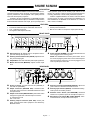
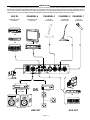
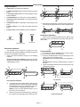
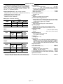
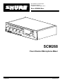
Shure Brothers Incorporated
222 Hartrey Avenue
Evanston IL 60202-3696 U.S.A.
Shure SCM268 Mixer
SCM268
Four-Channel Microphone Mixer
E1998, Shure Brothers Inc.
27A8606 (RD)
Printed in U.S.A.
SHURE SCM268
DESCRIPTION
The Shure Model SCM268 is a transformer-balanced, fourchannel microphone mixer. Its simple, compact design delivers
superior performance and exceptional sound quality with low
noise and a flat frequency response.
Versatile in all types of applications, the SCM268 integrates
transformer-balanced XLR inputs, a switchable microphone/line
level transformer-balanced XLR output, phono jack inputs and
S
S
S
S
output, phantom power, and an auxiliary input channel. It can
function as a primary or add-on mixer for sound reinforcement,
recording, broadcast, or audio-visual presentation systems.
With the supplied hardware, the mixer’s half-rack chassis
mounts securely in single or dual rackmount installations. For
fixed installations, the SCM268 can be fastened on or below a
shelf, counter, or tabletop.
FEATURES
S
S
S
Four transformer-balanced microphone inputs
Transformer-balanced output—switchable mic/line level
Five –10 dB line-level inputs
Six-segment LED output level meter
Built-in 12-volt phantom power
Internal power transformer
Built-in low-cut filter on microphone inputs (below 80 Hz)
FRONT PANEL
Ê
Ë
Ì
Í
Ê
Ë
Gain Controls (1–4). Adjusts gain for microphone level inputs and auxiliary level inputs 1–4.
Auxiliary Channel Gain Control (AUX IN). Adjusts the auxiliary channel input gain.
Output Meter. LED meter indicates peak output signal level.
Î
Master Gain Control (MASTER). Adjusts overall output
level.
Ì
Í
Î
Power Indicator (POWER). This LED illuminates when the
unit is plugged in and receiving power.
NOTE: The SCM268 does not have a power switch. To turn
the unit off, unplug the power cord or use an external power
strip with a switch. However, it can remain plugged in as it
uses very little power when idle.
REAR PANEL
Ê
Ë
Ì
Í
Ê
Ë
Ì ÍÏ Î
Ð
Power Connector. Accepts 100–120 Vac (SCM268) or
220–240 Vac (SCM268E).
Output Connector (MIC/LINE OUT). Transformer-balanced XLR output connector. Switchable between line and
microphone level.
Output Level Switch (MIC/LINE OUT). Recessed switch
changes the signal level of the XLR output connector:
In = Microphone Level
Out = Line Level
Auxiliary Output Connector (AUX OUT). Phono jack
feeds consumer-level audio equipment. Not affected by
MIC/LINE switch.
Î
Ï
Ð
Ñ
English – 1
Ñ
Auxiliary Level Inputs (AUX LEVEL INPUTS, 1–4). Phono
jacks connect to consumer-level audio sources.
Auxiliary Input Channel (AUX IN). A dedicated auxiliarylevel input for the auxiliary channel.
Phantom Power Switch (12V PHANTOM). Recessed
switch turns on phantom power for microphone inputs 1–4.
Microphone Level Inputs (MIC LEVEL INPUTS). Transformer-balanced, microphone-level XLR inputs.
Input Gain
GAIN CONTROL
Output Gain
The gain control knobs 1–4, located on the front panel, adjust
the gain for both microphone and auxiliary-level inputs of channels 1–4 (see Figure 1). For example, the channel 1 gain control
is used for both the channel 1 microphone input (MIC LEVEL INPUT 1) and the channel 1 auxiliary level input (AUX LEVEL INPUT 1). The auxiliary gain control knob (AUX IN) affects only the
auxiliary input (AUX IN).
The master output gain control knob (MASTER) adjusts gain
to both the XLR balanced output (MIC/LINE LEVEL) and the auxiliary level output (AUX LEVEL).
Auxiliary Channel
Channel 3
Channel 1
Channel 2
Channel 4
Master Output
GAIN CONTROL
Figure 1
OUTPUT LEVEL METER
The six LEDs on the front panel labeled OUTPUT LEVEL
METER illuminate to reflect the peak level of the mixed output signal from the SCM268 (in reference to balanced line output) in dBu
(0 dBu = 0.775 V).
GREEN—Nominal
Use the master gain control (MASTER) to adjust peak levels,
as indicated by the LEDs. The red LED illuminates when the output is 2 dB below clipping.
RED—Clip
Peak Level
in dBu
PHANTOM POWER
When the phantom power switch on the back panel is on
(12V PHANTOM—ON), the SCM268 provides 12 V of phantom
power to each XLR microphone input. The switch is recessed to
prevent accidental engagement. Most condenser microphones
require phantom power. Use it when connecting these types of
microphones to the SCM268.
NOTE: Phantom power does not affect the operation of balanced
dynamic microphones. With phantom power on, they can be connected to the SCM268 in combination with condenser microphones that do use it.
OFF
ON
LINE
MIC
Phantom Power Switch
OUTPUT LEVEL SWITCH
The output level switch on the back panel (MIC/LINE OUT)
sets the level of the balanced XLR output. When set to MIC, it reduces the output by about 50 dB. Set the switch so that the output
level matches the input level of the device to which you are connecting the SCM268. The switch is recessed to prevent accidental engagement.
NOTE: The output level switch does not affect the auxiliary output
(AUX OUT) level.
English – 2
Output Level Switch
CONNECTIONS
The following diagram illustrates a few of the many types of connections possible with the SCM268. Note that nothing is connected to
the channel 4 microphone input (MIC LEVEL INPUT 4). This is because channel 4 is being used for the consumer-level equipment connected to the channel 4 auxiliary level input (AUX LEVEL INPUT 4). Connecting both auxiliary level and microphone level inputs to a
single channel is not recommended because the SCM268 would not be able to independently mix the two sources.
AUX IN
CHANNEL 4
CHANNEL 3
CONSUMER-LEVEL
EQUIPMENT
CONSUMER-LEVEL
EQUIPMENT
DYNAMIC
MICROPHONE
CHANNEL 2 CHANNEL 1
CONDENSER
MICROPHONE
DYNAMIC
MICROPHONE
CD PLAYER
OR
AM/FM RECEIVER
OR
VCR
TAPE DECK
POWER SUPPLY
ÁÁÁ
Á
ÁÁ
Á
POWER
AMPLIFIER
LOUDSPEAKERS
ÁÁ
Á
OR ÂÂÂ
ÂÂÂ
ÂÂÂ ÂÂÂ
ÂÂÂ ÂÂÂ
ÂÂÂ
ÂÂÂ
LINE OUT
OR
70 V P.A.
English – 3
OR
AUX OUT
INSTALLATION
Supplied Hardware
S
S
S
S
S
S
S
S
4 rubber feet. For stand-alone installation.
1 rackmount bracket, long. For half-rack (single unit) installations.
1 rackmount bracket, short. For half-rack (single) or dualmount installations.
2 straddle brackets. For dual-mount or fixed installations.
12 bracket screws, 1/4 in. (6 mm). For securing the brackets
to the chassis.
4 rackmount screws, 1 in. (2.5 cm). For mounting the unit in
a rack.
4 plastic washers. For use with the supplied rackmount
screws.
2. After attaching the brackets, mount the unit in an equipment
rack using the supplied rackmount screws and plastic washers.
4 wood screws, 1/2 in. (1.25 cm). For fixed installations.
Stand-Alone Installation
Adhere the four (4) supplied rubber feet to the bottom of the
unit at each corner. This will keep it from sliding and protect the
table surface.
Bracket Screw
Rackmount Screw
Wood Screw
Rackmount Installation
The SCM268 can be mounted as a single unit or dualmounted with either another SCM268 or another Shure half-rack
unit such as the SCM262 or DFR11EQ.
1. Attach the rackmount brackets using one of the following
methods:
Single unit (half-rack) installation: Attach the short and
long rackmount brackets to the SCM268 with eight (8) of the
supplied bracket screws.
Fixed Installation
To permanently affix the SCM262 above or below a table,
shelf, or counter top, use the following steps:
3. Fasten the straddle brackets to the recessed edges of the
chassis using four (4) bracket screws.
Top mount: Fasten the straddle brackets to on the bottom of
the unit
Hanging mount: Fasten the straddle brackets to the top of
the unit.
4. Fasten the straddle brackets to the surface using the four (4)
supplied wood screws.
TOP MOUNT
Dual-mounted installation:
a)
Connect the two units together side-by-side using two
(2) straddle brackets. The brackets should straddle the
recessed edges on on the top and bottom of each chassis. Fasten them using eight (8) bracket screws.
NOTE: Be sure to use both straddle brackets—one on
the top and one on the bottom.
b)
Attach the short rackmount brackets to the outsides of
the combined units with eight (8) of the bracket screws.
English – 4
HANGING MOUNT
INTERNAL MODIFICATIONS
The following table lists the low-cut frequency corners for
some of the most common capacitor values:
WARNING!
Voltages in this equipment are hazardous to life. No
user-serviceable parts inside. Refer all servicing to
qualified service personnel.
Capacitor Value (mF)
Low-Cut Frequency Corner (Hz)
.033
803
.047
564
.068
390
Disassembly
To access the printed circuit board (pc board) for internal
modifications, use the following steps:
1. Unplug the power cord.
2. Remove the knobs and retainer nuts from the front panel
(See Figure 2).
KNOB ASSEMBLY
Figure 2
.1
265
.22
120
.33
80
.47
56
.68
39
1.0
26.5
2.2
12
Phantom Power Disable
3. Remove the four screws at each corner of the back panel.
4. Remove the two screws at each bottom corner of the front
panel
5. Slide the back panel and pc board out from the rear of the
chassis.
CAUTION: When reassembling the SCM268, DO NOT OVERTIGHTEN the knob retainer nuts. Use a minimal amount of force
to secure the nut (0.6–0.8 N⋅m (5–7 in⋅lb)). Damage to the internal
components will result if too much force is used.
To disable phantom power for a given microphone input, remove the specified resistor as listed in the following table:
Channel
Remove Resistor:
1
R15
2
R25
3
R35
4
R45
Low-Cut Filter
To bypass the built-in low-cut filter for a given channel, remove the specified resistor and place a 10mF to 33mF capacitor in
the specified pc board location (polarity does not matter). Refer to
the following table:
Line Pad
To insert a 50 dB line pad for a given microphone input, remove the specified resistor and short the solder points at the specified pc board locations. Refer to the following table:
Channel
Remove Resistor
from:
Place 10mF to 33mF
Capacitor in:
Channel
Remove Resistors:
Short Solder Points:
1
R18
X17
1
R12, R13
X11 and X14
2
R28
X27
2
R22, R23
X21 and X24
3
R38
X37
3
R32, R33
X31 and X34
4
R48
X47
4
R42, R43
X41 and X44
To select a particular corner frequency for the low cut filter,
remove the R18, R28, R38, or R48 resistor for a given channel as
specified above. Then, in the corresponding pc board location
(X17, X27, X37, or X47), place a capacitor of the specified value
(polarity does not matter). Refer to the following formula for selecting the correct capacitor value for the desired corner frequency.
C=
26.5
F
where:
C = value of capacitor in mF
F = corner frequency (–3 bB) for low-cut filter in Hz
English – 5
SPECIFICATIONS
Measurement Conditions (unless otherwise specified): Line
voltage 120 Vac, 60 Hz (SCM268) or 230 Vac, 50 Hz (SCM268E);
full gain; 1 kHz, one channel activated; source impedances: Mic
150 Ω, Aux Level 150 Ω; terminations: Line 600 Ω, Mic 600 Ω, Aux
Out 10 kΩ. 12 V phantom power off.
Frequency Response (Ref 1 kHz, controls centered)
Microphone Inputs: 150 Hz to 20 Khz ±2 dB (built-in 80Hz low-cut)
Auxiliary Inputs: 20 Hz to 20 kHz ±2 dB
Low-Cut Filter (Microphone inputs only)
3dB down at 80 Hz, 6 dB/octave
Gain (typical, controls full clockwise)
Inp t
Input
Low-impedance
mic (150 Ω)
Aux Level
Mic
38 dB
Output
Line
76 dB
Aux Out
65 dB
3 dB
40 dB
29 dB
Inputs
Input
Mic
Aux Level
Impedance
Actual
Designed
(typical)
for use
with
19-600 Ω
≤2 kΩ
1.2 kΩ
21 kΩ
Input
Clipping
Level
–5 dBV
>28 dBV
Outputs
Output
Mic
Line
Aux Out
Impedance
Actual
Designed
(typical)
for use
with
low-Z inputs
>600 Ω
>2 kΩ
0.2 Ω
72 Ω
870 Ω
Output
Clipping
Level
–21 dBV
+18 dBV
+7 dBV
Total Harmonic Distortion
<0.25% at +4 dBu output level (through 22 Hz-22 kHz filter; Input 1
and Master centered, all other controls full counterclockwise)
Hum and Noise
Equivalent Input Hum and Noise . . . . . . . . . . . . . . . . –124 dBV
(150 Ω source; through 22 Hz - 22 kHz filter)
Output Hum and Noise (through 22 Hz to 22 kHz filter; channel
controls full counterclockwise)
Master full counterclockwise . . . . . . . . . . . . . . . . . . . . . –92 dBV
Master full clockwise . . . . . . . . . . . . . . . . . . . . . . . . . . . –70 dBV
Common Mode Rejection
>80 dB at 1 kHz
Polarity
All inputs to all outputs are non-inverting
Overload and Shorting Protection
Shorting outputs, even for prolonged periods, causes no damage.
Microphone inputs are not damaged by signals up to +10 dBV;
Auxiliary inputs by signals up to +36 dBV
Phantom Power
12 Vdc open-circuit through 340Ω series resistance
Operating Voltage
SCM268: 100–120 Vac rated nominal, 50/60 Hz, 60 mA
SCM268E: 220–240 Vac rated nominal, 50/60 Hz, 30 mA
Temperature Range
Operating . . . . . . . . . . . . . . . . . . . –7° to 49° C (20° to 120° F)
Storage . . . . . . . . . . . . . . . . . . . . –29° to 74° C (–20° to 165° F)
Overall Dimensions
44 mm H x 218 mm W x 162 mm D
(1.72 x 8.60 x 6.37 inches)
Net Weight
1.20 Kg (2 lbs, 11 oz)
Certifications
SCM268: UL & cUL Listed by Underwriters Laboratories, Inc.
SCM268E: Conforms to European Union directives, eligible to
bear CE marking; VDE GS-Certified to EN 60 065; meets European Union EMC Immunity Requirements (EN 50 082–1, 1992)
Replacement Parts
Knob, Master (blue) . . . . . . . . . . . . . . . . . . . . . . . . . . . . . 95B8752
Knob, Channel Gain (white) . . . . . . . . . . . . . . . . . . . . . . 95A8752
Line (Power) Cords:
SCM268: 100–120 Vac (US/Canada) . . . . . . . . . . . 95A8762
SCM268E: 220–240 Vac (EU) . . . . . . . . . . . . . . . . . 95A8778
Fuse, SCM268 (5x20 mm, 250V, 80mA, slow-blow) . . 80A730
Fuse, SCM268E (5x20 mm, 250V, 40mA, slow-blow) . 80J258
Optional Accessories
Line (Power) Cord, 230–240 Vac (UK) . . . . . . . . . . . . . 95A8713
English – 6