1
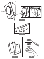
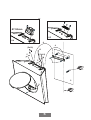
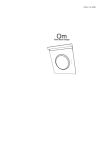
LI2WRA
Mini Om
Design Lorenzo Lispi
6
CLICK!
3
5
2
1
4
1
2
3
4
F
Ø 150mm
B
11A
11F
B
4
4
(5x18)
10
6
(5x18)
5
6
5
3
7
8
2
9
1
5
INSTRUCTION ON MOUNTING AND USE
GB
Description of the hood - Fig. 1
1
2
3
4
5
6
7
Control panel
Grease filter
Grease filter release handle
Halogen lamp
Vapour screen
Air outlet
Telescopic flue (optional)
Operation
Description of control panel and hood operation
coupling, accompany it upward.
Closing the steam screen:
Accompany the steam screen downwards, press firmly
and check the resulting coupling.
Grease filter
This must be cleaned once a month using non aggressive
detergents, either by hand or in the dish-washer, which must
be set to a low temperature and a short cycle.
When washed in a dish-washer, the grease filter may
discolour slightly, but this does not affect its filtering capacity.
Removing the grease filters - Fig. 2
Open the steam screen.
Pull the handle downwards and extract the filter.
Charcoal filter (filter version only)
D
C
B
A
A. on/off light switch
B. on/off aspiration switch and minimum power
selection
B+C. medium power selection aspiration switch
B+D. maximum power selection aspiration
switch
Use the high suction speed in cases of concentrated kitchen
vapours. It is recommended that the cooker hood suction
is switched on for 5 minutes prior to cooking and to leave
in operation during cooking and for another 15 minutes
approximately after terminating cooking.
Maintenance
Prior to any maintenance operation ensure that the cooker
hood is disconnected from the power supply.
Cleaning
The cooker hood should be cleaned regularly internally and
externally.
For cleaning use a cloth moistened with denatured alcohol
or neutral liquid detergents. Avoid abrasive detergents.
Warning:
Failure to carry out the basic standards of the cleaning of the
cooker hood and replacement of the filters may cause fire
risks.
Therefore we recommend oserving these instructions.
Steam screen
The steam screen must always be left closed and opened
only for maintenance (e.g. cleaning or changing filters).
Opening the steam screen:
Press the lower part of the steam screen firmly. After
It absorbs unpleasant odours caused by cooking.
The charcoal filter can be washed once every two months
using hot water and a suitable detergent, or in a dish-washer
at 65°C (if the dish-washer is used, select the full cycle
function and leave dishes out).
Eliminate excess water without damaging the filter, then
remove the mattress located inside the plastic frame and put
it in the oven for 10 minutes at 100° C to dry completely.
Replace the mattress every 3 years and when the cloth is
damaged.
• Montage - Fig. 3
Open the steam screen and remove the grease filter.
Install the carbon filter on the back of the grease filter and
fix with two rods.
Attention! The rods are included in the carbon filter
packing and not on the hood.
• To dismantle the filter act in the reverse manner.
Replacing lamps - Fig. 4
Firstly check that the lamps are well cooled prior to replacing
them.
Access the light compartment – extract the guard by levering
it off with a small screwdriver or similar tool.
Replace the damaged light bulb.
Only use halogen bulbs of 20W max (G4), making sure you
do not touch them with your hands.
Close the lamp cover (it will snap shut).
If the lights do not work, make sure that the lamps are
fitted properly into their housings before you call for
technical assistance.
Caution
This appliance is designed to be operated by adults. Children
should not be allowed to tamper with the controls or play with
the appliance.
Do not use the cooker hood where the grill is not correctly
fixed! The suctioned air must not be conveyed in the same
channel used for fumes discharged by appliances powered
by other than electricity. The environment must always be
adequately aerated when the cooker hood and other
8
INSTRUCTION ON MOUNTING AND USE GB
appliances powered by other than electricity are used at the
same time. Flambé cooking with a cooker hood is
prohibited. The use of a free flame is damaging to the filters
and may cause fire accidents, therefore free flame cooking
must be avoided. Frying of foods must be kept under close
control in order to avoid overheated oil catching fire. Carry
out fumes discharging in accordance with the regulations in
force by local laws for safety and technical restrictions.
Installation - Fig. 5
Consult the designs in the front pages referenced in the text
by alphabet letters. Closely follow the instructions set
out in this manual. All responsibility, for any eventual
inconveniences, damagxes or fires caused by not complying
with the instructions in this manual, is declined.
The hood must be at a distance of not less than 40 cm from
the cooking top with electric plates.
If the instructions for installation for the gas hob specify a
greater distance, this must be adhered to.
The hood is supplied in the FILTERING version and is used
without an extracted fumes discharger conduit .
Fumes and steam are recycled through the F deflector (11F).
If you intend using the product in the SUCTION version, it
is necessary to have an evacuation conduit going from the
upper B exit to the extraction hole towards the exterior.
In this case a connection ring (11A) has to be installed on
the B extraction hole and the carbon filter removed.
A telescopic flue is available (as an accessory).
Preliminary information for installation of the hood
Expansion wall plugs are provided to secure the hood to
most types of walls/ceilings. However, a qualified technician
must verify suitability of the materials in accordance with the
type of wall/ceiling. The wall/ceiling must be strong enough
to take the weight of the hood.
Do not tile, grout or silicone this appliance to the wall.
Surface mounting only.
In the case of the presence of panels and/or walls and/or
lateral wall units check that there is sufficient space to install
the hood and that access to the command panel is easy.
Only for some models
An aesthetic flue can be purchased as an optional accessory.
Check with the assistance centre whether the model in your
possession envisages this possibility.
We advise installing the hood after having purchased the flue
to check with certainty the most suitable installation.
During electrical connection ensure the power supply is
disconnected at the domestic main switch.
• Trace a centre line on the wall to facilitate the montage
(1), position the hole template so that the middle line
printed on it corresponds to the centre line previously
drawn and that the lower side of the grill corresponds to
the lower part of the hood once mounted (2).
• Make two holes with the 8 mm Ø drill and fix the support
bracket with two dowels and wall screws (3).
•
•
•
•
•
Open the steam screen and remove the grease filter (see
relative paragraph).
Hang up the hood (4), adjust its position (5-6) and mark
1 point from the inside of the hood for the definitive fixing
(7). Remove the hood and make a Ø 8 mm hole with
the drill (8), insert the wall dowel and hang the hood up
again and fix it definitively with 1 screw (9).
Connect the electricity (10), but leave the hood
disconnected from the general electric panel of the
house.
Install the supplied flange (11A –suction version– also
install a discharge tube of suitable dimensions) or the
deflector (11F – filtering version).
Mount the grease filter and close the steam screen.
Attention! If the hood is to be used in the suction version,
remove, if supplied with the kit, the carbon filter and the
fixing rods (on the back of the grease filter – see relative
paragraph).
If the hood is to be used in the filtering version, check that
the carbon filter is already mounted on the back of the
grease filter or, in its absence, purchase it and install it.
Electrical connection
The electrical tension must correspond to the tension noted
on the label placed inside the cooker hood. Connect the
electrical plug, where provided, to the an easily accessible
outlet in conformity with local standards in force.
Where an electrical plug is not provided (for direct connection
to electrical network) place a standards approved bipolar
switch with an aperture distance of not less than 3mm
(accessible) from the contacts.
This appliance is marked according to the European directive
2002/96/EC on Waste Electrical and Electronic Equipment
(WEEE). By ensuring this product is disposed of correctly, you
will help prevent potential negative consequences for the
environment and human health, which could otherwise be
caused by inappropriate waste handling of this product.
on the product, or on the documents
The symbol
accompanying the product, indicates that this appliance may not
be treated as household waste. Instead it shall be handed over
to the applicable collection point for the recycling of electrical and
electronic equipment. Disposal must be carried out in accordance
with local environmental regulations for waste disposal.
For more detailed information about treatment, recovery and
recycling of this product, please contact your local city office,
your household waste disposal service or the shop where you
purchased the product.