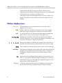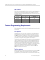
1
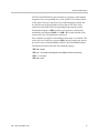
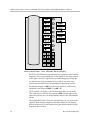
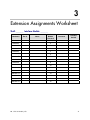
Siemens Hicom/HiPath optiset
LinkPlus Interface Guide
for SpectraLink e340/h340/i640
Wireless Telephones
July 2008 Edition
1725-36143-001
Version K
LinkPlus Interface Guide: Siemens Hicom/HiPath optiset for SpectraLink e340/h340/i640 Wireless Telephones
Trademark Information
Notice
Polycom® and the logo designs
SpectraLink®
LinkPlus
Link
NetLink
SVP
Are trademarks and registered trademarks of
Polycom, Inc. in the United States of America
and various countries. All other trademarks
used herein are the property of their respective
owners.
Polycom, Inc. has prepared this document for
use by Polycom personnel and customers. The
drawings and specifications contained herein
are the property of Polycom and shall be neither
reproduced in whole or in part without the prior
written approval of Polycom, nor be implied to
grant any license to make, use, or sell equipment
manufactured in accordance herewith.
Patent Information
The accompanying product is protected by one
or more US and foreign patents and/or pending
patent applications held by Polycom, Inc.
Copyright Notice
Copyright © 1998 to 2008 Polycom, Inc.
All rights reserved under the International and
pan-American copyright Conventions.
No part of this manual, or the software
described herein, may be reproduced or
transmitted in any form or by any means, or
translated into another language or format, in
whole or in part, without the express written
permission of Polycom, Inc.
Do not remove (or allow any third party to
remove) any product identification, copyright or
other notices.
Polycom reserves the right to make changes in
specifications and other information contained
in this document without prior notice, and the
reader should in all cases consult Polycom to
determine whether any such changes have been
made.
No representation or other affirmation of fact
contained in this document including but not
limited to statements regarding capacity,
response-time performance, suitability for use,
or performance of products described herein
shall be deemed to be a warranty by Polycom
for any purpose, or give rise to any liability of
Polycom whatsoever.
Contact Information
Please contact your Polycom Authorized
Reseller for assistance.
Polycom, Inc.
4750 Willow Road,
Pleasanton, CA 94588
http://www.polycom.com
Every effort has been made to ensure that the
information in this document is accurate.
Polycom, Inc. is not responsible for printing or
clerical errors. Information in this document is
subject to change without notice and does not
represent a commitment on the part of Polycom,
Inc.
2
PN: 1725-36143-001_K.doc
About This Guide
Polycom is the market leader in multi-cellular wireless telephone
systems for the workplace. We manufacture a range of products to
suit any size installation. SpectraLink 8000 Telephony Gateway uses
our LinkPlus digital integration technology to integrate with various
digital switch platforms. Using LinkPlus technology, SpectraLink
e340/h340/i640 Wireless Telephones emulate digital telephone sets to
deliver advanced capabilities such as multiple line appearances and
LCD display features. This document explains the programming or
administration required to use the host digital switch with the
SpectraLink 8000 Telephony Gateway and SpectraLink
e340/h340/i640 Wireless Telephones.
Different models of SpectraLink Wireless Telephones vary in
functional capabilities. This document covers the basic operational
features of all handsets. However, certain handset or PBX features
may not be supported by your emulation.
Related Documents
SpectraLink 8000 Telephony Gateway: Administration Guide for SRP
(1725-36028-001)
SpectraLink e340/h340/i640 Wireless Telephone: Configuration and
Administration (SRP) (72-1065-09)
Available at
http://www.polycom.com/usa/en/support/voice/wi-fi/wi-fi.html
Telephone Switch Interface Matrix (1725-36128)
Available at
http://www.polycom.com/usa/en/support/voice/wifi/pbx_integration.html
PN: 1725-36143-001_K.doc
3
LinkPlus Interface Guide: Siemens Hicom/HiPath optiset for SpectraLink e340/h340/i640 Wireless Telephones
Customer Support
Polycom wants you to have a successful installation. If you have
questions please contact the Customer Support Hotline at
(800) 775-5330. The hotline is open Monday through Friday,
6 a.m. to 6 p.m. Mountain time.
For Technical Support: [email protected]
For Knowledge Base:
http://www.polycom.com/usa/en/support/voice/voice.html
Icons and Conventions
This manual uses the following icons and conventions.
Caution! Follow these instructions carefully to avoid danger.
Note these instructions carefully.
Label
4
This typeface indicates a key, label, or button on SpectraLink
hardware.
PN: 1725-36143-001_K.doc
1
Plan the Interface
The system administrator programs the telephone system for use with
the SpectraLink 8000 System using the normal administration
terminal or procedures. Programming can be done after the handsets
are registered.
Recommended programming includes assigning extension numbers
to the handsets and programming features on the telephone system so
they are easily accessible from the handsets.
For analog interfaces, macro codes are in the document relating to
configuring the system. See SpectraLink 8000 Telephony Gateway:
Administration Guide for SRP.
The following information will help the system administrator set up
the SpectraLink e340/h340/i640 Wireless Telephones to operate in a
way that feels familiar and comfortable to users.
Plan Programming
Digital Interface programming for the SpectraLink e340/h340/i640
Wireless Telephones will be faster if it is planned in advance by
verifying the parameters and features on the current telephone
system and wired phones. The system administrator must assign
extension numbers to the handsets and plan the functions (trunk
access, toll restrictions, system features, ringing options etc.) to be
programmed for the handsets.
It may also help to identify a key layout that is programmed exactly
or close to the way the handsets should be programmed, and use the
programming for that set as a model for programming the handsets.
Line appearances
The handsets support two line appearances for the Hicom 150/
HiPath 3000 and four line appearances for the Hicom 300/HiPath
4000. Determine what extension numbers will be assigned to the
PN: 1725-36143-001_K.doc
5
LinkPlus Interface Guide: Siemens Hicom/HiPath optiset for SpectraLink e340/h340/i640 Wireless Telephones
handsets, which line or lines should ring at which handset; and which
line will be selected when the user goes off-hook.
Programmable feature keys
The handsets support programmable keys as shown in the key-map
diagrams below. Determine which features, if any, should be
programmed on the handsets. Feature keys that are not subject to
programming restrictions (described in the Programming Requirements
section) can be programmed to any optiset feature on the handset and
do not have to match the assignments on the user’s desktop
telephone.
Assign Extension Numbers
The wire contractor should inform the system administrator which
port numbers have been designated for the handsets.
The system administrator may use the Extension Assignments
Worksheet at the end of this document to track the port numbers,
extensions, users, and features assigned to handsets.
6
PN: 1725-36143-001_K.doc
Plan the Interface
The SpectraLink Wireless Telephone
(not to scale)1
SpectraLink e340 Wireless Telephone
SpectraLink i640 Wireless Telephone
The handset has a pixel-based alphanumeric display (up to 4-line x
16-character), plus line and status indicators. The user can toggle
between two display views in order to see all 24 possible characters
per line sent by the Hicom CS. At the start of each call the leftmost 18
characters are displayed. Pressing LINE + ► displays the remaining
eight characters truncated from the initial screen. Pressing LINE + ◄
displays the leftmost 18 characters. When the left characters are being
displayed a right arrow icon is displayed. This indicates that the user
can press LINE + ► to see more characters to the right. Likewise, when
the right characters are being displayed a left arrow icon is displayed
indicating that the user can press LINE + ◄ to see characters at the
beginning of the line.
When the Power On/Start Call button is used to power on the handset, it is referred to as the Power On
button. When it is used to initiate a call or other action, it is referred to as the Start Call button.
1
When the Power Off/End Call button is used to power off the handset, it is referred to as the Power Off
button. When it is used to end a call or for some other action, it is referred to as the End Call button.
PN: 1725-36143-001_K.doc
7
LinkPlus Interface Guide: Siemens Hicom/HiPath optiset for SpectraLink e340/h340/i640 Wireless Telephones
Certain characters may be used by the Hicom CS that are not
implemented in the handset. Flashing characters are not implemented
on the handset, nor is rolling or scrolling of text.
Although the optiset E Basic telephone does not have a display, any
display information sent by the Hicom CS will be displayed on the
handset.
Wireless Telephone Icons
▪▪3▪▪▪▪▪▪
The line indicators are associated with line access keys. In the
diagram, line 3 is active.
◄►
A left or right arrow is displayed when the screen can be toggled
either left or right to display more characters as described above.
▲▼
Up and down arrows are displayed when the menu has additional
options above or below what is shown in the display area.
The battery icon displays and a soft beep will be heard while the
Wireless Telephone is in use whenever the Battery Pack charge is low.
User has 15–30 minutes of Battery Pack life left.
The signal strength icon indicates the strength of the signal and can
assist the user in determining if the handset is moving out of range.
The voicemail icon indicates that you have a new voicemail message
Low battery
This message will display and an alarm will sound while the Wireless
Telephone is in standby mode and the Battery Pack is critically low.
The Wireless Telephone cannot be used until the Battery Pack is
charged.
The download icon indicates that the handset is downloading code.
This icon only appears while the handset is running the over-the-air
downloader. It appears to the right of the Signal Strength icon in the
same location as the Voicemail icon.
[Melody]
8
A melody is played after the Wireless Telephone is powered on for
the first time following a completed charge (Charge Complete).
PN: 1725-36143-001_K.doc
Plan the Interface
Handset Modes
Standby(on-hook)
In the standby mode the handset is waiting for an incoming call or for
the user to place an outgoing call. The extension number is shown on
the display and there is no dial tone. In this mode, the handset is
conserving battery power and bandwidth.
Active (off-hook)
To place a call, press the Start Call key. This transitions the handset to
active off-hook mode. There is a dial tone, the handset is in
communication with the PBX and the display shows information as it
is received from the PBX. The handset is also in the active mode when
you receive a call.
The active modes utilize the most bandwidth and battery power. To
conserve these resources, return the handset to the standby mode
when a call is completed by pressing the End Call key.
Active (on-hook)
To access the on-hook features of the handset, it must be in the active
on-hook mode. To transition from the active off-hook mode to the
active on-hook mode, press the Start Call key. In this mode, the user
may access the on-hook OptiGuide features. Return to the standby
mode by pressing the End Call key when finished accessing the onhook features.
PN: 1725-36143-001_K.doc
9
LinkPlus Interface Guide: Siemens Hicom/HiPath optiset for SpectraLink e340/h340/i640 Wireless Telephones
LED emulation
When Lines are programmed as shown on the key-map diagrams, the
numeral icons on the handset display will be mapped to the LEDs
associated with the corresponding Feature Keys. The line icons will be
displayed as follows:
Line State
optiset LED Status
On-hook
Off
Handset
Line Status Icon State
Off
Off-hook
On
On
Ringing
Rates 2, 3, 5, & 6
Fast flash
On hold
Rates 4 & 7
Slow flash
Feature Programming Requirements
When planning the interface, the following information must be taken
into account:
Line sequences
The handset uses two types of key sequences to access PBX features
and multiple lines. Line sequences are those where the user presses
the LINE key and then a number key. The key-map design designates
“line” optiset E keys that should be programmed for line appearance
so that they correspond to line sequences on the handset.
The line icon on the handset will reflect activity on the corresponding
optiset E telephone key. For this reason, it is recommended that line
appearance keys on both the Hicom 150/HiPath 3000 Basic optiset E
and the Hicom 300/HiPath 4000 Standard optiset E should be used
only for line access. If only one line is assigned to a particular handset,
leave the other designated line keys identified on the key maps
unassigned on the optiset E. The handset key sequences LINE +2 to
LINE +4 will then have no function.
Function sequences
Function sequences are those where the handset user presses the FCN
key and then a number key. Designated “function” deskset keys
programmed to system features such as Transfer and Conference may
10
PN: 1725-36143-001_K.doc
Plan the Interface
have their corresponding menu items display on the handset function
menu. See the key-map diagram for the function keys that are
available for feature programming.
Hold
The Hold feature may be programmed to a softkey as shown in the
softkey programming table so that the Hold function is available on
the handset.
Mute
The handset Mute function is handled locally within the handset. The
Mute function may be programmed to a softkey as shown in the
softkey programming table so that the Hold function is available on
the handset.
Voicemail
The voicemail icon on the handset is activated with the message
indication of the optiset E. The Mailbox or PhoneMail feature on the
optiset E must be assigned to the feature key as shown in the ey-map
diagrams. Do not assign any other feature to this key, since the
associated LED is directly mapped to the message-waiting icon on the
handset. This LED assignment must be used in order to support the
message-waiting icon. Using this key for any other feature or for line
access could cause unacceptable system performance.
Speakerphone
Because the handset has no speaker, speakerphone function and
functions that require the use of the volume keys will not be made
available on the handset. Disable all speakerphone features,
particularly any hands-free features that activate the speaker with the
telephone on-hook.
Ring types
Handset ring types (soft, normal, vibrate, etc.) are programmed by the
handset user and are not accessible or changeable by the Hicom
switch. Whenever possible the audible ringer on the handset will
follow the cadence provided by the Hicom switch. Call progress tones
provided by the host Hicom CS will be passed through to the handset.
PN: 1725-36143-001_K.doc
11
LinkPlus Interface Guide: Siemens Hicom/HiPath optiset for SpectraLink e340/h340/i640 Wireless Telephones
OptiGuide menu
The OptiGuide menu provides access to features appropriate to the
current context of the handset. You may navigate through the menus
by using the default programming: FCN + * (Previous), FCN + 0
(Select), FCN + # (Next). Navigation and selection options should be
programmed to the softkeys as described in the following section. To
access the off-hook features of the OptiGuide menu, place the handset
in the off-hook active mode by pressing Start Call. To access the onhook features, press Start Call again to enter the on-hook active mode.
Pressing the Start Call key again will return the handset to the off-hook
active mode. Press the End Call key to enter the standby mode.
In the Hicom 150 and HiPath 3000 systems the optiset E Basic
telephone does not have OptiGuide context-sensitive feature keys.
However, the key codes used for the OptiGuide keys are recognized
by the host Hicom CS and can be used on the handset. Refer to the
key-map diagram notes.
Prime Line impacts
If a handset is used in conjunction with an optiset desk telephone,
each phone is configured on the Hicom CS as an independent phone
with its own phone number (each device is assigned to a separate
Prime Line). In order for both an optiset E telephone and a handset to
ring together, the extensions need to be set up at the Hicom CS to ring
at the same time.
A called party’s display of the originating line will be different when
the handset makes the call compared to the optiset telephone. The
name text could identify the source of the call to avoid confusion. For
example, the display name of the handset could be stored as “Smith
WT” at the Hicom CS. Display names should be kept to a minimum
so the full name is displayed on the handset (see the SpectraLink
Wireless Telephone section above for more details).
It should also be noted that the class of service (COS) of the handset is
related to the Prime Line of the phone and not the line appearance.
Speed dial
Users should be made aware that stored speed dial and redial
features will have to be saved separately for the optiset E telephone
and the handset. Additionally, the Last Number Redial feature will
only apply to the device from where the original number was dialed.
12
PN: 1725-36143-001_K.doc
Plan the Interface
Hicom 300/HiPath 4000 Phone Test access code
The Hicom 300/HiPath 4000 Phone Test (access code*940) will not
work on the SpectraLink e340/h340/i640 Wireless Telephones.
Button programming
For the Hicom 150/HiPath 3000, phone button programming (access
code *91) will not work. All button programming must be done by the
administrator and not the user.
PN: 1725-36143-001_K.doc
13
2
Interface Implementation
This section describes the recommended programming to use the
SpectraLink 8000 Telephony Gateway with the Siemens Hicom 150/
HiPath 3000 E and 300 E/H Communications Server (CS). The
procedures assume:
•
The Siemens Hicom CS system is installed and initialized.
•
A trained Siemens technician or system administrator will be on
site with the Installer to program the system.
Set the Switch Interface Type
Connect to the SpectraLink 8000 Telephony Gateway using the serial
or modem interface. From the Main Menu, choose Gateway
Configuration. Scroll to Telephone Switch Type and press enter to
change this field, from the Submenu of PBX types, select Hicom 150/
HiPath 3000 or 300. Refer to the SpectraLink 8000 Telephony Gateway:
Administration Guide for SRP document for details on configuring the
Telephone Switch.
Programming the Softkeys on the Handset to Emulate optiset E
Functionality
The following table illustrates how the softkeys on the handset may
be programmed so that they conform to the default emulation
described in the diagrams on the next pages. Programming the
softkeys will override the default programming. Softkeys and
shortcut sequences may be programmed to additional features as
well. See the corresponding table and instructions in the section on
programming the softkeys and shortcut keys in the SpectraLink 8000
Telephony Gateway: Administration Guide for SRP document.
PN: 1725-36143-001_K.doc
15
LinkPlus Interface Guide: Siemens Hicom/HiPath optiset for SpectraLink e340/h340/i640 Wireless Telephones
Level
0
1
Softkey
A
Shortcut
Menu Label
Hold
Softkey Label
Hold
Action
Hold
B
*
Previous
<– –
F*
C
0
Select
OK
F0
D
#
Next
– –>
F#
A
1
Mute
Mute
Mute
B
2
Mail
Mail
F2
C
D
Siemens optiset Diagrams
The diagrams on these pages illustrate additional features that may be
programmed to softkeys and shortcut keys.
Siemens optiset E Standard - Hicom 300/HiPath 4000 Key-mapping
16
PN: 1725-36143-001_K.doc
Interface Implementation
The FCN and LINE labels represent the key sequence on the handset
mapped to the corresponding key on the optiset E. The feature labels
to the right of the keys represent one possible mapping scheme, but
any feature may be programmed to keys that do not have setup
restrictions described in the Programming Requirements section.
The handset displays a LINE icon that corresponds to each line key
identified in the diagram (LINE + 1 to LINE + 4). See the handset Icons
section below for an explanation of the icons.
The voicemail icon lights on the handset when there is voicemail. This
is the only use for this key sequence (FCN + 2) and requires the optiset
key shown above with the Mailbox label for the PhoneMail® feature.
The handset function menu has these default settings:
FCN + 0 = Select
FCN + 2 = Voicemail (corresponds to the Mailbox feature key above)
FCN + * = Previous
FCN + # = Next
PN: 1725-36143-001_K.doc
17
LinkPlus Interface Guide: Siemens Hicom/HiPath optiset for SpectraLink e340/h340/i640 Wireless Telephones
PQRS
TUV
WXYZ
7
8
9
*
0
#
Siemens optiset E Basic - Hicom 150/HiPath 3000 Key-mapping
The FCN and LINE labels represent the key sequence on the handset
mapped to the corresponding key on the optiset E. The feature labels
to the right of the keys represent one possible mapping scheme, but
any feature may be programmed to keys that do not have setup
restrictions described in the Programming Requirements section.
The handset displays a LINE icon that corresponds to each line key
identified in the diagram (LINE + 1 to LINE + 2).
The Voicemail icon lights on the handset when there is voicemail.
This is the only use for this key sequence (FCN + 2) and requires the
optiset key shown above with the Mailbox label for the PhoneMail®
feature.
The OptiGuide™ Select, Previous, and Next keys do not exist on the
optiset E Basic desktop telephone, but these functions will display
and can be accessed on the handset using the default function menu
sequences shown below.
18
PN: 1725-36143-001_K.doc
Interface Implementation
The handset function menu has these default settings:
FCN + 0 = Select
FCN + 2 = Voicemail (corresponds to the Mailbox feature key above)
FCN + * = Previous
FCN + # = Next
PN: 1725-36143-001_K.doc
19
3
Extension Assignments Worksheet
Shelf: _______ Interface Module: _______
Handset 1
Interface
Module
Circuit #
1
Handset 2
2
Handset 3
3
Handset 4
4
Handset 5
5
Handset 6
6
Handset 7
7
Handset 8
8
Handset 9
9
Handset 10
10
Handset 11
11
Handset 12
12
Handset 13
13
Handset 14
14
Handset 15
15
Handset 16
16
Handset #
Ext. #
PN: 1725-36143-001_K.doc
Name
Comment
Handset
Serial #
21