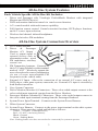
1
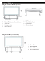
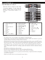
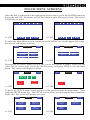
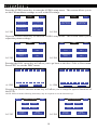
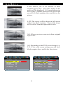
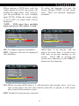
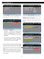
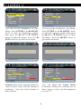
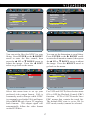
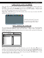
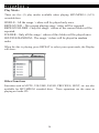
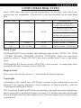
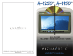
™ Table of contents Important Safety Instructions.................................................................1 Package Content.....................................................................................2 System Overview...................................................................................3 Installation..............................................................................................4 Cable Connection...................................................................................6 IR Remote Control.................................................................................8 Touch Menu Screens..............................................................................9 System Settings.................................................................................... 11 Compatible Disc Types........................................................................21 Technical Specification........................................................................23 ™ Welcome Congratulations on your purchase of the Vizualogic RoadTrip RT Series. This system will provide your family with many years of enjoyment. This sophisticated product provides video entertainment to rear seat passengers without altering the appearance of your vehicle’s original interior. Reviewing this owner’s manual thoroughly prior to operation will provide you with the best performance and help explain the simple requirements for proper care. ▲ Important safety instructions ▲ CAU T I ON RISK OF ELECTRIC SHOCK CAUTION: DO NOT OPEN TO REDUCE THE RISK OF ELECTRIC SHOCK, DO NOT REMOVE COVER (OR BACK). NO USER SERVICEABLE PARTS INSIDE. REFER SERVICING TO QUALIFIED SERVICE PERSONNEL. CAUTION: The unit employs a laser system. To ensure proper use of this product, please read this owner’s manual carefully and retain for future reference. Should the system require The lightning flash with arrowhead maintenance, contact an authorized service symbol within an equilateral triangle location, see service procedure. is intended to alert the user to the presence of dangerous voltage within Use of controls, adjustments of the performance the product’s enclosure that may be of procedures other than those specified herein of sufficient magnitude to constitute may result in hazardous radiation exposure. a risk of electric shock. To prevent direct exposure to laser beam, DO The exclamation point within an NOT try to open the enclosure. Visible laser equilateral triangle is intended to alert radiation may be present when the enclosure is the user to the presence of important opened. DO NOT stare into the laser beam. ▲ ▲ operating and maintenance (servicing) instructions in the literature accompanying the appliance. WARNING: FCC regulations states that any change or modification to the equipment, not expressly approved by the maker or its authorized parties could void the user’s authority to operate this equipment. NOTE: -- Please dispose of empty batteries according to local regulations in your country. -- All On-Screen-Displays (OSD) and pictures will be based on the English version. -- Design and Specifications may vary in the manual from the actual product in use. 1 ™ Package Content AUX Cable (1) USB Cable (1) 2 ™ All-In-One System Features Each Vehicle Specific All-In-One Kit Includes: • • • • • • Driver and Passenger side Vizualogic PerfectMatch Headrest with integrated Monitor and DVD Player(s). DVD and monitor function control via touch screen function. A/V control module with multi-source capability. Full function remote control. Controls monitor functions, DVD player functions, and A/V source input selection. Wireless dual channel infrared headphones. Integrated wireless FM modulator. All-In-One System Connection Overview 1. A/V Control Module 2. Driver & Passenger Monitor A/V Output Used to output signal to external devices such as aftermarket radios, wired FM modulators, auxiliary screen’s ect. 3. FM Transmitter Antenna - Connects to the A/V Control Module via the terminal marked “ANT”. Wirelessly outputs the user-selected audio sources information via one of seven user-selectable FM frequencies to the vehicle radio. 4. External A/V Input - Allows the connection of an external A/V source such as a DVD player, video game system, camcorder, etc. External A/V input is viewable by both headrest monitors. 5. Grey System Connector 6. Driver Monitor (Monitor A) Connectors - These color-coded outputs connect to the color-coded input terminals coming from the Driver Headrest. 7. Passenger Monitor (Monitor B) Connectors - These color-coded outputs connect to the color-coded input terminals coming from the Passenger Headrest. 8. System Power Input Terminal - Connects to the System Power Harness. 9. White System Connector. 10. System Power Harness - Connects to the power input terminal on the white system connector. Wires are color-coded and labeled as follows: Yellow - +12 BATT (Constant Power) Red - +12 ACC (Accessory Power) Black - Ground Green - Parking Brake Note: Parking brake wire does not need to be connected for system to operate. 3 ™ Headrest Installation Section I - Headrest Installation 1. Remove the factory headrests (Detailed instructions can be found in the vehicle’s service manual. 2. Starting with the driver’s side headrest (Monitor A) insert the mini-din connectors into the driver side headrest post guides. 3. Slowly push the cables into the seat. If an obstruction is encountered, pull back slightly on the cable and rotate before continuing. Route the cables so that they exit the bottom of the seatback. 4. Repeat steps 2 and 3 for the passenger’s side headrest (Monitor B). Section II - Wiring 1. Place the A/V Control Module in a well protected area under a seat or behind a panel. 2. Insert the Monitor's system connector cables into the A/V Control Module. These connectors will click and lock into place when fully inserted. 3. Route the monitor and DVD cables from each headrest towards the A/V Control Module. If additional length is necessary use the available cable extensions. NOTE: The available extensions are not interchangeable the cable connector colors must match. 4. Connect these cables from the driver side headrest (Monitor A) to the DRIVER MONITOR (Monitor A) the A/V Control Module. 5. Connect these cables from the passenger side headrest (Monitor B) to the PASSENGER MONITOR (Monitor B) on the A/V Control Module. 6. Connect the wireless FM modulator antenna to the connector jack on the side of the A/V control Module labeled ANT. 7. Extend and route the FM modulator antenna under the carpet or behind a panel ensuring to avoid any sharp metal edges or moving parts. For best results do not coil or bundle the FM modulator antenna. NOTE: If the vehicle has an aftermarket radio that accepts RCA auxiliary inputs or the use of a wireless FM modulator is not desired, simply remove the modulator antenna and connect RCAs to the Driver Monitor A/V Output (located on the side of the A/V control module) and route them to the desired component. 8. Plug the power harness into the A/V control module and connect the power wire leads to 12V+ and 12V ground. The wires are color coded as follows: Red = ACC Power, Yellow = Constant Power, Black = Ground, Green = Parking brake. 4 ™ Section III - System Set-up/Sub-Menu Controls Enter the Sub-Menu, touch the “MENU” button on the screen to enter the SubMenu. Use the “” and “” buttons to move up and down within the SubMenu. Once the desired item has been highlighted, press the “MENU” button until the desired setting is achieved. IR CHANNEL – This function changes the IR channel that the monitor transmits from: Ch.‘A’, Ch.‘B’ or ‘OFF’ NOTE: The driver’s side monitor is factory preset to ‘A’ and the passenger side monitor is factory preset to ‘B’. DO NOT set both monitors to the same IR channel, as this causes audible interference through the IR headphones. SCREEN - Sets the power-up mode for the monitor when system power is turned on. • “AUTO” - While in this mode the monitor will resume the last state it was in when the system power was last turned off. • “ON” - When system power is turned on, the monitor will always turn on. • “OFF” - When system power is turned on, the monitor will always remain off. The monitor must be turned on manually using the power button on the monitor or remote. DVD MODE - Assigns the headrest identity to ensure proper source identification between Driver DVD, Passenger DVD, Ext. Aux, and Aux. via the on-screen display (OSD). NOTE: The dual DVD headrest system’s default setting for the driver’s side is set to ‘Monitor 1’ and ‘Monitor 2’ for the passenger side. The single DVD headrest system’s default setting for the driver’s side is set to ‘DS’ and ‘PS’ for the passenger side. Do not set both screens to Monitor 1 / DS or Monitor 2 / PS. These settings must be observed in order to utilize the integrated FM modulator functions properly. EXIT - Exits the sub-menu. 5 ™ Single & Dual DVD System 7 9 8 6 5 4 1. 2. 3. 4. 5. 3 2 1 6. 7. 8. 9. Power Button Infrared Transmitter/Power Indicator AUX Jack Headphone Jack Mini USB Port DVD Loader Touch Screen Panel Eject Button SD Card Reader Single DVD System Only 1. 2. 3. 4. 6 Power Button Power Indicator Infrared Transmitters LCD Touch Screen ™ Single & Dual DVD System Monitor 1 DS A1285 Monitor 2 PS A1285 POWER A/V OUTPUTS ANT EXTERNAL A/V INPUT Single DVD System Only Monitor 1 DS A1285 Monitor 2 PS A1286 POWER A/V OUTPUTS ANT EXTERNAL A/V INPUT 7 ™ 19 20 21 22 The IR Remote Control Point the remote control no more than 3-4 meters (approx. 21 feet) from the remote control sensor on the front of the player. Keep remote within a ± 30˚ angle. 1. 2. 3. 4. 5. 6. 7. 8. 9. 10. 11. 12. Adjust Decrease Adjust Increase Title Eject Number Buttons Clear Slow Program Mute Repeat Zoom Play / Pause 13. 14. 15. 16. 17. 18. 19. 20. 21. 22. 23. 24. 1 2 3 4 5 6 7 8 9 10 11 12 13 14 15 16 17 18 23 24 25 26 27 28 29 30 31 32 33 34 Right Arrow Stop / Return Fast Reverse Fast Forward Previous Next Monitor Menu Power Menu/PBC Source Subtitle Display 25. 26. 27. 28. 29. 30. 31. 32. 33. 34. Audio USB / SD Up Arrow Setup Enter Left Arrow Down Arrow FM Volume + Volume - NOTE: -- The distance may vary according to the brightness of ambient light. -- If the remote is not used for an extended period of time, remove the batteries to prevent possible damage from battery leakage and/or corrosion. -- DO NOT place any objects between the remote control unit and the sensor on the RT System. -- DO NOT use the remote control unit while simultaneously operating a remote control unit from another device. They may interfere with each other resulting in improper operation. --Depending on usage, the batteries in the remote control should normally last for about one year. If the remote control isn’t working, replace the batteries with new batteries and try again. -- DO NOT mix old batteries with used ones. -- DO NOT mix rechargeable batteries with non-rechargeable batteries. -- Incorrect usage of batteries may cause them to leak, corrode or explode. -- If leakage from the batteries occur, properly clean the battery compartment before attempting to install new batteries. -- Make sure the IR sensor is not obstructed by any objects. 8 ™ Touch Menu Screens Once the unit is connected to the appropriate power source, press the POWER button to power the unit ON. Touch any area of the screen to enter the menu screen. The screen will display as below. Main Menu A-1285 Main Menu ent exit exi t A-1286 ent exit exit To enter the Main Menu screen, simply press the MENU key on the upper left corner. The screen will display as below. Main Menu back exit Main Menu back Audio Video Audio Video Source Setup Source Setu p Disc Menu DVD functions A-1285 exit A-1286 Pressing the SOURCE menu key will take you to the SOURCE menu. Here you can select the AV source type. Select the desired source and press EXIT to exit the main menu. The screen will display as below. Main Source Main exit Source exit SDSD DVDcard DVD carduSb Aux input Aux input other Monito r A-1285 A-1286 To get to the SETUP menu, touch any area of the screen to enter the main menu. Then press the SETUP menu key. The SETUP screen allows you to setup the basic functions of the unit. The screen will display as below. back Setup exit back language - english + Power o n - With car + language - english + reset Defaults enter DVD Setup rese t Defaults A-1285 A-1286 9 Setup exit Power o n - With car + ™ Press the AUDIO menu key to enter the AUDIO setup menu. This screen allows you to set the FM modulator settings as well as the IR settings. Audio back A-1285 fM contro l -this Screen+ ir headphone - channel A + fM Source -this Screen+ fM radio ou t - 88.1 Mhz + Audio back exit exit ir headphone - channel b + fM contro l -other Screen+ A-1286 Press the VIDEO menu key to enter the VIDEO setup menu. This screen allows you to adjust the picture settings. Video back exit Video back exit - brightnes s 100% + - contrast 100% + - brightnes s 100% + - contrast 100% + - Saturatio n 100% + - Sharpnes s 100% + - Saturatio n 100% + - Sharpnes s 100% + A-1285 A-1286 Pressing the DISC menu key will allow you to go back to the disc's Title or Root menu. Press EXIT to exit the DISC menu. Main Menu A-1285 back title Men u ent exit exi ok Main Menu exit A-1286 root Menu back title Men u ent exit exi ok exit root Menu Pressing the DVD Functions menu key will allow you to setup the special functions of the DVD. NOTE: DVDs with the following function(s) may be required to use the function keys. back A-1285 DVD functions exit back DVD functions Audi o Subtitle Audi o Subtitle Angl e repeat Angl e repeat Arrows / number s enter DVD Setup A-1286 10 Arrows / number s exit enter DVD Setup ™ System Settings Press SETUP on the Remote Control to enter the system setting menu. Current Item --G eneral S etup Page -TV Display Angle Mark OSD Language Captions Screen Saver Last Memory Current Item Wide ON ENG Off ON ON Goto general setup page On the Remote Control, press either the UP or DOWN or LEFT or RIGHT arrow buttons to move to the desired menu item and press PLAY to select the menu item. --G eneral S etup Page -TV Display Angle Mark OSD Language Captions Screen Saver Last Memory PS ON ENG Off ON ON 4:3 PanScan 4:3 Letterbox 16:9 Goto general setup page Set TV Display mode to the correct ratio: • Press the RIGHT arrow buttons to enter the sub-menu. If you want to set the screen to "WIDE", press the DOWN arrow twice to move your selection until the "WIDE" item is selected, press ENTER to select. • Press SETUP to exit these system settings. NOTE: There are three (3) screen ratio modes available: 16:9 WIDE, 4:3LB (Letter Box) and 4:3PS (Pan Scan). Different disc formats will display different images depending on the screen setting and size used. Here is an example of the different screen ratio format. 11 ™ 4:3LB Allows you to see movies in their original aspect ratio. The entire frame of the movie will be displayed. 16:9 recorded movies will occupy a smaller portion of the screen and you will see black margins above and below the picture. 4:3PS The movie will be shown in full screen without any black margins. Parts of the image will be cutoff from the right and left side. 16:9 Allows you to see movies in their original aspect ratio. 16:9 Depending on the DVD screen format (e.g. 2.35:1), the wide screen setting may still have black margins above and below the picture. --G eneral Setup P age -- - - General S etup P age -TV Display Angle Mark OSD Language Captions Screen Saver Last Memory PS ON ENG Off ON ON TV Display Angle Mark OSD Language Captions Screen Saver Last Memory On Off PS ON ENG Off ON ON Set OSD Language Set Angle Mark 12 English German French Spanish Italian Portuguese Dutch Danish ™ When playing a DVD disc with the Angle option set to ON, the screen will display the angle mark. This will give you the possibility to view multiple angle DVDs. When the Angle option is set to OFF, no angle mark will be displayed. NOTE: DVD must have multiple angle options for this option to work. To select the language for your On Screen Display (OSD) use this menu item. There are multiple languages available. - - General S etup P age -TV Display Angle Mark OSD Language Captions Screen Saver Last Memory PS ON ENG Off ON ON --G eneral S etup Page -TV Display Angle Mark OSD Language Captions Screen Saver Last Memory On Off Captions PS ON ENG Off ON ON On Off Screen saver ON: To display captions (Subtitles). OFF: Captions will not be displayed (No Subtitles) When there is no activity with the player for some time, a screen saver will start to prevent damage to the screen. Select ON to activate the screen saver function or select OFF to deactivate this function. - - General S etup P age -TV Display Angle Mark OSD Language Captions Screen Saver Last Memory PS ON ENG Off ON ON On Off Set last memory state ON: When you turn off the player, it will memorize the last play time. So if you turn on the player the next time and the same disc is played, it will resume play from the last memory point. OFF: Disable the last memory function. 13 ™ - - Audio S etup P age- - --E qualizer Page -- Analog audio setup Equalizer 3D Processing HDCD Sound Mode Bass Boost Super Base Treble Boost Select the EQUALIZER menu item to setup your preferred Equalizer mode. Press ENTER to enter this selection. You can select one of these preset Equalizer modes to adjust the audio signal to your liking. Press ENTER to enter the Analog Audio setup page. The next page will be shown: - - Analog audio setup page -STR Off Rock Pop Live Dance Techno Classic Soft Select Equalizer Type GOTO Audio Setup page Downmix OFF Off Off Off LT/RT Stereo --E qualizer Page -Sound Mode Bass Boost Super Base Treble Boost Set downmix mode Set sound mix output mode: --Press the RIGHT arrow to enter the sub-menu. If you want analog stereo signals, set the sound mode to "STEREO"; press the DOWN arrow once to move the selection to "STEREO", than press ENTER. OFF Off Off Off On Off Bass Boost --E qualizer Page -Sound Mode Bass Boost Super Base Treble Boost --If you want to have Dolby Pro Logic stereo (the decoded signal will create a 2ch reality simulating effect via the R/L connectors), select "LT/RT" then press ENTER. OFF Off Off Off On Off Super Bass You can select one of these modes to adjust the Bass and Treble signal to your liking. ON will switch the selected mode on and OFF will switch it back to normal Audio playback. --E qualizer Page -- NOTE: Please be advised that sometimes the BASS on an Audio CD or DVD is already very low, using the Bass Boost or Super Bass can overload your speakers resulting in poor sound quality. Sound Mode Bass Boost Super Base Treble Boost OFF Off Off Off Treble Boost 14 On Off ™ --V ideo setup page -- - - 3 D processing page -Pro logic ii Revers mode Off Color Setting Off Concert Living Room Hall Bathroom Cave Arena Church Go to video setup page Reverb MODE Select this menu item to setup your Video Quality modes. Press ENTER to enter this selection. Select 3D PROCESSING to setup your preferred 3D mode. Press PLAY to enter this selection and to set up your preferred Audio mode for a better surround effect. Press ENTER or the RIGHT arrow to enter this selection. color setting setup Color setting setup Filter Sharpness Brightness Contrast Gamma Hue Saturation Luma Delay 1X Off 1X 2X Mio 00 00 NONe 00 00 1T High Medium Low Sharpness Filter You can set the picture sharpness to these choices. If a video image is light, select the LOW option. If a video image is dark, select the HIGH option. Select HDCD to setup your preferred Audio mode for HDCD. Press ENTER to enter this selection and to setup your preferred filter mode for HDCD (default is 1X). 1x = 48K Sampling, 2x = 96K Sampling 15 ™ Color setting setup color setting setup Sharpness Brightness Contrast Gamma Hue Saturation luma delay sharpness brightness contrast gamma hue saturation luma delay Mio 00 00 NONe 00 00 1T Mio 00 00 NONe 00 00 1T contrast brightness You can set the Brightness to your liking. Press ENTER or the RIGHT arrow to enter the brightness control, then press the UP or DOWN arrow to adjust the image. Press the LEFT arrow to go back to the menu. You can set the Contrast to your liking. Press ENTER or the RIGHT arrow to enter the contrast control, then press the UP or DOWN arrow to adjust the image. Press the LEFT arrow to go back to the menu. brightness iiiiiiiii.......0 contrast iiiiiiiiii......0 brightness contrast color setting setup color setting setup sharpness brightness contrast gamma hue saturation luma delay sharpness brightness contrast gamma hue saturation luma delay Mio 00 00 NONe 00 00 1T high medium low none Mio 00 00 NONe 00 00 1T ot 1t luma delay gamma You can adjust the Luma Delay (Luminance Delay) by selecting one of these choices to best suit the brightness of your TV. Gamma refers to the exponent between video or pixel values and the displayed brightness. You can set the Gamma to these choices. 16 ™ color setting setup color setting setup sharpness brightness contrast gamma hue saturation luma delay sharpness brightness contrast gamma hue saturation luma delay Mio 00 00 NONe 00 00 1T hue Mio 00 00 NONe 00 00 1T saturation hue Iiiiiiiiiiiiii..........0 saturation iiiiiiiiii......0 hue saturation You can set the Hue (for NTSC) to your liking. Press ENTER or the RIGHT arrow to enter the Hue control, then press the UP or DOWN arrow to adjust the image. Press the LEFT arrow to go back to the menu. You can set the Saturation to your liking. Press ENTER or the RIGHT arrow to enter the Saturation control, then press the UP or DOWN arrow to adjust the image. Press the LEFT arrow to go back to the menu. - - Preference page - tv type PBC Parental default PAL off -- P reference page -tv type PBC Parental default PAL multi NTSC Set tv standard PAL OFF on off set pbc state Select this menu item to set up your preferred video output format. PAL is commonly used in Europe while NTSC is commonly used in the USA and Japan. Select MULTI only if your TV supports both formats. The output signal will automatically follow the video format on the DVD disc. For VCD and SVCD, this selection turns ON or OFF the Playback Control (PBC) function. VCD or SVCD media have PBC menus that contain the track list. The default PBC state is set to ON. In OFF mode, track(s) cannot be selected. 17 ™ - - Preference page - tv type PBC Parental default PAL OFF -- P reference page -tv type PBC Parental default 1- kid saf 2- g 3- pg 4- pg 13 5- pg r 6- r 7- nc 17 8- adult SET PARENTAL CONTROL PAL OFF reset load factory setting Set Age Control Grade: With this option you can select to reset to the factory preset values. For DVD discs with a rating system programmed (North America CARA) parents can prohibit watching content that might be inadvisable for children. Press the RIGHT arrow to enter the submenu. If you want to change the age control grade press either the ▲ UP or DOWN arrow to scroll to the available selections. Selection 1 is Kid safe. Selection 2 is General Audiences. Selection 3 is PG (Parental Guidance Suggested, some material may not be suitable for children). Selection 4 is PG-13 (Parents strongly cautioned, some material may be inappropriate for children under 13). Selection 5 is PG-R (Restricted, under 17 requires accompanying parent or adult guardian). Selection 6 is Restricted Viewing. Selection 7 is NC-17 (No one 17 and under admitted). Selection 8 is for Adult Entertainment or X rated movies. Hereafter, a screen will indicate to enter a password, if the factory password has never been modified, you can use [123456] by pressing the corresponding number buttons on the remote control. Select “YES” or “NO” with either the left or right arrow key and press ENTER to confirm. -- P assword setup page -Password mode password on on off password mode With this option you can select to set your password protection ON or OFF. -- P assword setup page -Password mode password on change change password Use this menu to change the factory set password [123456]. OLD PASSWORD NEW PASSWORD CONFIRM PWD OK 18 ™ Creating a PIN Number Enter the PIN number with the number buttons of the remote control and press ENTER. Now enter the new password and press ENTER again. Confirm your new password and press ENTER again to save the PIN number. Please write down the PIN number and store in a safe location. Important: DO NOT forget the PIN number, there is no way to retrieve the PIN number if forgotten or lost. With this selection X you exit the system setup and return to normal viewing of the video. EXIT SETUP MENU MP3 / MPEG4 PLAYBACK The Vizualogic RoadTrip RT Series DVD Player is able to play CD-R/CD-RW recorded with MP3/MPEG4 audio and video files. When a disc with MP3 or MPEG4 files (including multiple directories) is loaded in the system the following screen will display. To go to the preferred music or video directory, press the ▲ and/or arrows to scroll to your selection and confirm your choice by pressing the ENTER button. To select your preferred song or video title, press the ▲ and/or arrows to scroll to your selection and confirm your choice by pressing the ENTER button. Your selected song or video will now play. 19 ™ Play Mode: There are five (5) play modes available when playing MP3/MPEG4 (.AV1) recorded discs: SINGLE - All the songs / videos will be played only once. REPEAT ONE - The current playing song / video will be repeated. REPEAT FOLDER - Only the songs / videos of the current folder will be repeated. FOLDER - Only all the songs / videos of this folder will be played once. SHUFFLE/RANDOM - The songs / videos will be played in random order. When the disc is playing, press REPEAT to select your repeat mode, the Display will show: Other Functions Functions such as MUTE, VOLUME, PAUSE, PREVIOUS, NEXT, etc. are also available for MP3/MPEG4 recorded discs. These operations are the same as playing an Audio CD. 20 ™ Compatible disk types Some DVD discs may have special requirements for playing, with which this system may not compatible. Please refer to the specifications on the individual disc. DISC TYPE Content Size Total Play Time About 4.7 GB - 2 hrs. (Single Side & Single Layer) DVD AUDIO/VIDEO 12CM About 8.5 GB - 4 hrs. (Single Side & Double Layer) About 9.4 GB - 4 hrs. (Double Side & Double Layer) About 17 GB - 8 hrs. (Double Side & Double Layer) CD-DA AUDIO 12CM About 700 MB - 74 Minutes MP3 MP3 AUDIO 12CM About 700 MB - 300 Minutes Discs Types The RoadTrip RT Series can play the following types of discs: DVD / CD / CD-R / CD-RW / DVD-R / DVD-RW / DVD+R / DVD+RW. Other discs not listed cannot be played. Please DO NOT play discs smaller than 12cm or odd shape discs. The RoadTrip RT Series uses the NTSC/PAL color systems. It cannot play discs recorded with other systems, such as SECAM. Region Code The region code for this player is 1 which indicate North America. Copyright According to the related laws, DVD discs without proper authorization are not allowed to be copied, broadcast, cable broadcast, or played publicly with the Vizualogic RoadTrip RT Series. The Vizualogic RoadTrip RT Series incorporates copyright protection technology that is protected by method of claims of certain U.S. patents and other Intellectual Property Rights owned by their rights owners. Reverse engineering or disassembly is prohibited. 21 ™ 22 ™ Specifications: ---------- Technical specifications Multimedia player supports: DVD, DVD-R, DVD-RW, DVD+R, DVD+RW, CD, CD-R, CD-RW, VCD, SVCD, MP3 and JPG picture disks. MPEG4 support: DivX 3.11/4.02/5.02/5.03/5.05 DivX Pro/Subtitles .srt .sub Electronic Shock Protection (ESP) and Mechanical Shock Protection PAL/NTSC compatible Multi Lingual On Screen Display (OSD) Integrated Dome Lights with Door Sensor Connections A/V input via RCA connectors USB Connector Multi-Language Menu Selection Kit Content: ------ Dual Monitors with Integrated DVD Players (RT20 Only) (2) - Wireless Headphones (Batteries Included) Remote Control (Battery Included) A/V Box with A/V Cables User Manual Specifications: Power Consumption 12V DC (1 1-15V) /1.4A (Max 1.6A) FM Stereo Transmitter 88.5MHz / 88.7MHz / 88.9MHz / 89.1MHz / 89.3MHz 89.5MHz / 89.7MHz / 89.9MHz IR Carrier Frequency 2.3 / 2.8 MHz TV Signal System PAL/NTSC/MULTI Laser Semi-conductor laser, wave length 600nm, 780nm Frequency Range 48 KHz pulse modulation 20 Hz ~ 22 KHz 96 KHz pulse modulation 20 Hz ~ 22 KHz S/N ≥ 65 dB Audio Dynamic Range > 85 dB Harmonic Distortion 0,01% Input Sensitivity 500 mv Operation Temperature 0 ˚C ~ 40 ˚C Storage Temperature -15 ˚C ~ 50 ˚C 23 ™ ™ 99-1285-001 DISCLAIMER FM Modulator Notification for all European Union Vizualogic Customers. Due to E-1 regulations pertaining to FM Modulation in aftermarket mobile electronics products, the following changes have been made for all Vizualogic headrest kits shipped to Europe: - The systems will be shipped with the default set to FM Modulator OFF. - The FM Modulators will be inoperable as the antenna has been removed and the antenna receptacle disabled. 1493 Bentley Drive - Corona - CA - 92879 www.vizualogic.com