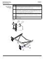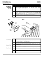
1
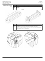
INSTALLATION
MANUAL
UL2 Front Mount
MODELS
4400 FM
6600 FM
HydroHoist Boat Lifts
®
R
HydroHoist Marine Group
P.O. Box 1286 Claremore, OK USA 74018
1-800-825-3379
www.boatlift.com
Pub. 10/14/08
HydroHoist Marine Group
HydroHoist Marine Group
Product Installation and
Use Warning Disclaimer
ASSEMBLY, INSTALLATION OR REPAIRS OF A HYDROHOIST BOAT LIFT SHOULD ONLY BE PERFORMED BY AN AUTHORIZED
HYDROHOIST TECHNICIAN. IF ASSEMBLY, INSTALLATION AND/OR REPAIR IS PERFORMED BY UNAUTHORIZED PERSONS,
SERIOUS PERSONAL INJURY AND/OR PROPERTY DAMAGE COULD OCCUR.
IF UNAUTHORIZED PERSONNEL ASSEMBLE, INSTALL OR REPAIR A HYDROHOIST BOAT LIFT, HYDROHOIST MARINE GROUP
HEREBY DISCLAIMS ANY AND ALL WARRANTIES, EXPRESS OR IMPLIED.
HYDROHOIST MARINE GROUP, LIMITS ITS
WARRANTY TO HYDROHOIST MARINE GROUP'S PUBLISHED BOATLIFT WARRANTY FURNISHED WITH EACH PRODUCT. NO
OTHER WARRANTY OF ANY KIND EITHER VERBALLY OR IMPLIED INCLUDING WARRANTIES OF MERCHANTABILITY AND
FITNESS FOR A PARTICULAR PURPOSE ARE RECOGNIZED.
THE CONTENTS OF THIS MANUAL ARE SUBJECT TO CHANGE WITHOUT NOTICE AND SHOULD NOT BE CONSTRUED AS A
COMMITMENT, REPRESENTATION, WARRANTY OR GUARANTEE OF ANY METHOD, PRODUCT OR DEVICE BY HYDROHOIST
MARINE GROUP.
REPRODUCTION OR TRANSLATION OF ANY PART OF THIS MANUAL, WITHOUT THE WRITTEN PERMISSION OF HYDROHOIST
MARINE GROUP. IS PROHIBITED.
ANY INQUIRIES CONCERNING HYDROHOIST MARINE GROUP’S PUBLISHED WARRANTY OR THIS MANUAL AND ITS CONTENTS
SHOULD BE REFERRED TO:
CUSTOMER SERVICE
HYDROHOIST MARINE GROUP
915 WEST BLUE STARR DRIVE
CLAREMORE, OK USA 74017
PHONE 918-341-6811
OFFICE HOURS M-F 8AM TO 5PM CT
HydroHoist Marine Group
Safety Notice
TO ENSURE CONSUMER SAFETY, HYDROHOIST MARINE GROUP HAS INSTALLED IN THE CONTROL UNIT’S ELECTRICAL SYSTEM AN
AC GROUND FAULT CIRCUIT INTERRUPTER (GFCI) DEVICE WHICH IS TO BE USED IN SERIES WITH THE USER’S PRIMARY AC POWER
SOURCE. THE GFCI IS AN INTEGRAL PART OF THE HYDROHOIST BOAT LIFT AND IS DESIGNED TO OFFER A LIMITED MEASURE OF
PROTECTION TO THE USER AGAINST HAZARDOUS ELECTRICAL CONDITIONS OR SHOCKS SHOULD THEY OCCUR.
THE USER SHOULD BE AWARE OF THE FOLLOWING WARNING:
WARNING!
IF USER DISABLES THE CONTROL UNIT’S GROUND FAULT CIRCUIT INTERRUPTER (GFCI) DEVICE,
HE IS IN DIRECT CONFLICT WITH THE RECOMMENDATIONS OF THE UNITED STATES GOVERNMENT
CONSUMER PRODUCTS SAFETY COMMISSION. DISABLING THE GFCI COULD RESULT IN SEVERE
ELECTRICAL SHOCK OR DEATH.
BEFORE CONNECTING AC POWER TO THE CONTROL UNIT, BE CERTAIN THAT THE PRIMARY AC
POWER SUPPLY MEETS ALL APPLICABLE ELECTRICAL CODES.
ANY INQUIRIES CONCERNING THE GROUND FAULT CIRCUIT INTERRUPTER (GFCI) DEVICE SHOULD BE REFERRED TO:
CUSTOMER SERVICE
HYDROHOIST MARINE GROUP
915 WEST BLUE STARR DRIVE
CLAREMORE, OK USA 74017
PHONE 918-341-6811
OFFICE HOURS M-F 8AM TO 5PM CT
Introduction - I
HydroHoist Marine Group
Model: 4400/6600/ UL2FM
Publication: 10/14/08
CONTENTS
Getting Started - Section 1
Site Preparation - Section 2
Assembly - Section 3
Installation - Section 4
Final Adjustments - Section 5
Trouble Shooting - Section 6
Parts List - Section 7
Getting Started
Sec. 1 Pg. 1
HydroHoist Marine Group
Model: 4400/6600/ UL2FM
Publication: 10/14/08
Getting Started
Assembly Platform
Assembly should be done on a flat, level surface.
A flat-bed trailer is preferred, but a boat trailer with planks across the frame will work, provided
that the assembly surface is flat and level
Tools
A list of tools needed for hoist assembly is given below. In addition to these, tools for boat
dock preparation, dock bumper removal, etc. may also be required.
♦
♦
♦
♦
♦
♦
♦
♦
♦
♦
♦
♦
♦
♦
♦
Symbols &
Conventions
1/2” Drive Ratchet (minimum 9 inch handle length for leverage)
Electric Drill
3/4” Deep Well Socket
9/16” Deep Well Socket
(2) 15/16” Open-end or Combination Wrenches
3/4” Open-end or Combination Wrenches
9/16 Open-ended or Combination Wrenchs
5/16” Hex Wrench or Hex Tool Socket
5/16” Nut Runner or medium blade Slotted Screwdriver
Medium Phillips Screwdriver
Drift Pin or other hole aligning tool
Large Hammer (3 or 4 lb. shop hammer is best)
Knife or tool for cutting 1 1/4” rubber hose
Measuring Tape
3/4” Ratcheting Open-end wrench
All references to the LEFT or RIGHT are considered to be facing forward, as if driving a boat
into the slip. Left is Port side, Right is Starboard side.
Parts are occasionally described as LEFT or RIGHT to identify their opposing construction, not
location on the hoist.
All numbers in brackets [ ] after part names refer to the item numbers on the assembly
illustrations within the manual.
End of Section 1
Site Preparation
Sec. 2 Pg. 1
HydroHoist Marine Group
Model: 4400/6600/ UL2FM
Publication: 10/14/08
Site Preparation
Verify
The Boat Stall or Mooring Location.
♦
If the hoist is being installed in a commercial marina or multi-slip boat dock, confirm the
correct mooring location for hoist and boat.
The boat specifications.
♦
♦
♦
♦
♦
♦
♦
♦
♦
♦
Inspect
Make ____________________________
Model ___________________________
Length _____________
Beam ______________
Dry Weight of boat ________ lbs.
Fuel: _____ gal. @ 6.6 lbs./gal. = ______ lbs.
Water: ____gal. @ 7.5 lbs./gal. = ______ lbs.
Gear estimated @ 8% of boat’s dry weight ______lbs.
Other equipment or weight ________ lbs.
TOTAL LIFTING WEIGHT _____________ LBS.
The boat slip, dock or seawall to which the hoist will be installed.
♦
The structure should be of good, sturdy construction capable of maintaining a secure
mooring for the hoist.
♦
The Dock Brackets, which will be mounted on the dock to provide hoist mooring, have a
minimum gripping distance of 5 inches and a maximum gripping distance of 19 inches.
Confirm that there is sufficient dock structure for the Dock Brackets.
♦
The HydroHoist 4000FM requires a minimum of 7 feet, the 6000FM requires a minimum
of 7 feet 9 inches of water depth in which to operate. Confirm that there is sufficient
water depth at all times of the year.
Check for underwater obstructions, such as structural braces, cables, rocks, or sunken
objects which will interfere with the hoist’s operation.
♦
♦
Check for overhead obstructions and confirm that sufficient clearance exists for the lifting
of the boat.
♦
Confirm that electrical supply is available and sufficient for hoist operation.
♦
Confirm that sufficient dock space is available for mooring the hoist and boat.
♦
CONFIRM THE BOAT LENGTH Boats with a center line length longer than 24 feet should not be installed on the 4000 FM.
Boats with a center line length longer than 26 feet should not be installed on the 6000 FM.
End of Section 2
Assembly
Sec. 3 Pg. 1
HydroHoist Marine Group
Model: 4400/6600/ UL2FM
Publication: 10/14/08
Assembly Instructions
Description
The assembly instructions presented within this section represent the steps for
assembling the Model 4400FM & 6600FM HydroHoist Boat Lift. It is
recommended that before assembling the components, you read and understand
each procedural step to become familiar with how all parts are assembled.
Tightening of Fasteners
In the assembly procedures, DO NOT TIGHTEN fasteners until directed to do so.
Insert bolts with appropriate washers, lock washers and nuts, but, unless otherwise
instructed, leave the fasteners loose to allow movement of the parts for adjustment
during assembly.
HydroHoist Marine Group
Model: 4400/6600/ UL2FM
Publication: 10/14/08
Assembly
Sec. 3 Pg. 2
Assembly
Sec. 3 Pg. 3
HydroHoist Marine Group
Model: 4400/6600/ UL2FM
Publication: 10/14/08
Tank Location
Fig. B
Step
1.1
Procedure
Align the Tanks [1] parallel with each other and with the Air Injection Nipple to the
front of the hoist assembly and in the 6 o'clock position.
Fig. B
6600 FM
4400 FM
Assembly
Sec. 3 Pg. 4
HydroHoist Marine Group
Model: 4400/6600/ UL2FM
Publication: 10/14/08
Tank Bracket Assembly
Step
Procedure
Fig. B
1.1
Fig B
Place the tube brackets [9] in the longitudinal channels which span the top of
the tanks.
Step
Procedure
1.2
Fig C
Snap the UL2 side brackets [14] into place, followed by placing the Single Piece
Tank Bracket [10] on top of the side bracket and attaching with fasteners.
Fasteners per single piece/plastic bracket: (2ea.) 1/2” X 2 1/2” Hex Head bolts, nuts,
and lock washers. (4ea.) 1/2” Flat Washers.
Assembly
Sec. 3 Pg. 6
HydroHoist Marine Group
Model: 4400/6600/ UL2FM
Publication: 10/14/08
Channel Assembly
Step
3.1
Fig. E
3.2
3.3
Procedure
Attach front and rear Cross Channel [11] to Single Piece Tank Brackets[10].
Note: Position Cross Channel [11] with flanges of Channel to rear of hoist.
Fasteners per Upper Tank Band: (4 ea.) 1/2” x 1-1/2” bolt, nut & lockwasher.
Attach Side Channels [13,14] with flanges of Channel facing inboard and square end
to rear, to Cross Channels [11] Fasteners per Channel: (8 ea.) 1/2” x 1-1/2” bolt, nut
& lockwasher with flatwasher on slotted holes.
Tip: For assembly by one person - A) Lift the rear of the Side Channel [14] into
position and temporarily secure it with a 1/2” x 5” bolt (found in parts bag). B)
Raise the front of the Side Channel and attach it loosely to the front cross Channel
[11] using 1/2” x 1-1/2” bolts. C) Return to the rear of the Side Channel, remove the
5” bolt, and secure using 1/2” x 1- 1/2” bolts
Attach center Cross Channel [11] to Side Channels [13,14]
Fasteners per Cross Channel: (8 ea.) 1/2” x 1-1/2” bolt, nut & lockwasher with
flatwasher on slotted holes.
Fig. E
Assembly
Sec. 3 Pg. 7
HydroHoist Marine Group
Model: 4400/6600/ UL2FM
Publication: 10/14/08
Note...
Positioning...
Fig. F
Hull Support
Assembly
The parts installed in the next steps may have to be moved to better fit the bottom of the boat after it has
been lifted. Accurate measurements of the boat’s hull before assembly and careful attention to these steps
may prevent repositioning the parts over the water.
If the boat hull is unable to be measured prior to hoist assembly, space the Hull Support Columns [4] 36”
to 42” apart at the rear of the hoist, and the front columns 3” narrower than the rear. Typically, the
longer leg of the column [4] is positioned vertically to lift the boat higher above the water, however the
shorter leg of the column may be positioned vertically to accommodate a boat with a deeper draft.
Step
4.1
Procedure
Attach two Hull Support Columns [4] to the front Cross Channel [11] and two Hull
Support Columns to the rear Cross Channel [11]. Attach the columns with the flat side
of the angles facing to the front of the hoist assembly, and the brace angle of the
column outboard. Fasteners per Column: (2 ea.) 1/2” x 1-1/2” bolt, nut & lockwasher.
4.2
Attach Hull Support Pads [2] to the tops of the front and rear Hull Support Columns
[4]. The pad’s long angle iron frame member should be inboard so that its weight
keeps the pad tilted inboard, toward the boat hull. Fasteners per Pad: (2 ea.) 1/2” x 5”
bolt, nut & lockwasher.
Install the Hull Support Pad Braces [3] between the Hull Support Pads [2] and the Hull
Support Columns [4]. The flat side of the braces face inboard. Fasteners per Brace: (1
ea.) 1/2” x 1-1/2” bolt, nut & lockwasher at Column; (1ea) 1/2” x 5” bolt, nut &
lockwasher at Hull Support Pad.
Tighten the 5” Hull Support Pad bolts only enough to flatten the lockwashers. Do not
tighten any other bolts at this time.
Fig. F
4.3
4.4
Fig. F
Front
Assembly
Sec. 3 Pg. 8
HydroHoist Marine Group
Model: 4400/6600/ UL2FM
Publication: 10/14/08
Frame Weldment
Assembly
Step
5.1
Procedure
Under the Frame Sections [13 & 14] suspend by rope or chain, a 2x4 x 8 foot board as
shown in Fig. G
5.2
With the “Square Tube Section” of the Frame Weldment Assembly [12] still on the
ground, lift the “Drop V” Section of the Weldment Assembly [12] and place on top of
the 2x4 board and in position to (later) be bolted to the frame.
Using a come-a-long attached at the front pivots, draw the Side Channels [13 & 14]
together as you raise the “Square Tube Section” of the Weldment Assembly [12] into
the bolting position, and loosely attach the “Square Tube Section” [12] to the Side
Channels. Fasteners per side: (4 ea.) 1/2” x 1-1/2” bolt, nut lockwasher and
flatwasher on slotted holes.
Attach the “Drop V” Section of the Frame Weldment Assembly [12} to the Side
Channels [13 & 14]. Fasteners per side: (4 ea.) 1/2” x 1-1/2” bolt, nut lockwasher
and flatwasher on slotted holes.
Fig. G
5.3
5.4
Fig. G
Pivot End
2 x 4 x 8’ Board
Suspended from
Frame
“Drop V” Section
“Square Tube” Section
Leveling the Hoist
Tightening All
Fasteners
Step
6.1
Procedure
Stand at the rear of the hoist and sight from the rear Cross Channel [11] to the front
Cross Channel to make sure the front and rear are parallel and that there is no twist or
warp in the hoist. If one corner appears to be low, place a block under that corner, as
necessary, to align the corners.
6.2
Stand at the side of the hoist and sight across the Side Channels [13 & 14] to make
sure that they are parallel and that there is no twist or warp in the hoist. If one corner
appears to be low, place a block under that corner, as necessary, to align the corners.
With the Unit Level Tighten all 1/2” bolts to approximately 65 ft.-lbs. of torque.
Exception: The 5” Hull Support bolts previously tightened. Note: When tightening
bolts on the frame, the end plates of the Cross Channels and Weldment Assembly
MUST be against the web of the side Channel - NO GAP should exist between the
parts.
6.3
HydroHoist Marine Group
Model: 4400/6600/ UL2FM
Publication: 10/14/08
Mooring Tube
Assembly
Sec. 3 Pg. 9
Step
7.1
Fig. H
7.2
7.3
7.4
Procedure
Determine the location of the Mooring Tube Assembly:
FM 4400 - the rear Cross Channel [11] is preferred, the center Cross Channel is
optional.
FM 6600 - the center Cross Channel [11] is mandatory.
Attach Mooring Pipe Clamp [18] to Cross Channel [11]. Fasteners: (4 ea.) 1/2” x 11/2” bolt, nut & lockwasher. Tighten these bolts at this time.
Insert short end of Mooring Pipe [19] into Mooring Pipe Clamp [18].
Adjustment: The distance from the center of the hoist to the inboard side of the
Mooring Pipe [19] should equal 1/2 of the boat’s beam plus 1 to 2 inches.
With the Mooring Pipe [19] properly positioned and vertical, tighten the bolts on the
Mooring Pipe Clamp [18]. Fasteners: (3 ea.) 1/2” x 2" bolt, nut & lockwasher.
Fig. H
Front Bumper
Step
8.1
Procedure
Attach Bumper [22] to Frame Weldment [12]. Fasteners: (4 ea.) Screws, self drilling
self tapping #12 x 7/8".
HydroHoist Marine Group
Model: 4400/6600/ UL2FM
Publication: 10/14/08
Assembly
Sec. 3 Pg. 10
Hose Assembly
Step
9.1
Procedure
Cut Hose [16] in half and secure one end of each hose to the nipple of the tank and
one end to the valve in the control. Secure with Hose Clamps.
Launching the Hoist
Step
10.1
Procedure
Secure the Control Unit [15] to a Hull Support Column [4] in the front of the Hoist.
Make sure that all valves are closed in the “Dry-Dock” position.
10.2
Insert Tank Plugs (Pt. No. 2905406) into the 6” Water Discharge Hole of EACH
Tank.
Note: DO NOT tow without Tank Plugs.
FM 4000 - Secure additional flotation, such as a block of Styrofoam, under the Frame
Weldment Assembly [22] - the flotation must be sufficient to prevent the hoist from
tipping forward when launched and towed.
Note: The FM 6000 does not require additional flotation, but flotation may be used
to stabilize the hoist in difficult towing environments.
Attach a towing line to the rear Cross Channel of the hoist.
Back the trailer into the water to float the hoist. Do this SLOWLY so that the front of
the hoist or Tanks will not pivot hard into the trailer.
Slowly tow the hoist to its mooring location.
10.3
10.4
10.5
10.6
End of Section 3
Installation
HydroHoist Marine Group
Model: 4400/6600/ UL2FM
Publication: 10/14/08
Installation
Sec.4 Pg. 1
Step
Procedure
Selecting Position for
Hoist
1.1
Move the hoist fully into the boat stall and position the Mooring Tube [19] 2 inches
from the side of the dock.
Fig. I
1.2
With the hoist held in the proper position, place a mark on the dock at TWO points:
1-The location of the Pivot Bushing of the left/port Side Channel [14].
2-The position of the Pivot Bushing of the right/starboard Side Channel [13].
Fig. I
Mark location of Pivot
Bushings on Side
Channels
Two inches between
Mooring Tube and dock
Front Dock Bracket
Step
2.1
Figs. I&J
2.2
Procedure
Attach Dock Brackets with the holes of the Vertical Angle [32] aligned with the mark
on the dock locating the position of the Pivot Bushings. Note: Grip Tabs [33] must
be installed to reduce movement of the Lower Dock Bracket Angle [30]. If Grip Tabs
are not applicable, it will be necessary to (later) through-bolt the Dock Bracket to the
dock structure to eliminate movement. Fasteners: 2 Grip Tabs per Dock Bracket - 2
ea 1/2” x 1” Carriage Bolt & nut.
Loosely tighten the 20” Dock Bracket Bolts [31]. It may be necessary to slightly
adjust the position of the Dock Brackets when attaching the hoist.
Fig. J
31
29
32
Dock Structure
6
30
33
Grip Tab
H.D Dock Bracket
Grip Tab
Installation
Sec.4 Pg. 2
HydroHoist Marine Group
Model: 4400/6600/ UL2FM
Publication: 10/14/08
Front Mooring
Attachment
Step
Procedure
3.1
Attach Pivot Connecting Bracket [7], with the pivot hole 10 inches above the water
line, to Vertical Angle [32] . Fasteners per Bracket: (2 ea.) 1/2" x 1-1/2" bolt, nut &
lockwasher. Tighten these fasteners at this time to 40 ft-lbs.
3.2
Attach Side Supports [13-14] to Pivot Connecting Brackets [7] using Bushings [2324] and Fasteners: (1 ea per Bracket) 5/8" x 3-1/2" Bolt, nut and lockwasher. Note: It
may be necessary to adjust the lateral position of the Dock Bracket to accomplish
attachment of the Side Supports to the Connecting Brackets.
3.3
With hoist attached to Dock Brackets, check the distance between the side of the dock
and the Mooring Pipe [19]. This distance should be 2 inches. If greater or less than 2
inches, adjust the lateral position of the Dock Brackets to accomplish the 2 inch
distance..
3.4
With the hoist in the proper position, tighten the 20" Dock Bracket Bolts [31] to about
35 ft-lbs of torque.
Fig. K
Fig. K
10 " to Waterline
Installation
Sec.4 Pg. 3
HydroHoist Marine Group
Model: 4400/6600/ UL2FM
Publication: 10/14/08
Side Mooring
Attachment
Step
4.1
Fig. L&M
4.2
4.3
Fig. L
Procedure
Assemble Mooring Collar Assembly [20] to Side Dock Bracket [8]. Fasteners: (2 ea.)
3/8" x 4-1/2" Bolt, Nut and Lockwasher. Note: The Collar Assembly may be
positioned high or low, by attaching to the Dock Bracket with either the Center and
Top holes, or Center and Bottom holes. The Collar Assembly can also be inverted,
allowing the Collar to be positioned lower on the Dock Bracket to accommodate
decks high above the water.
Slide the assembled Mooring Collar and Dock Bracket [20 & 8] over the Mooring
Pipe [19]. Position the assembly so that the Mooring Pipe [19] is to the FORWARD
END of the Mooring Color Slide. Note: As the hoist lowers, the Mooring Pipe will
pivot to stern - ample travel distance is provided in the Mooring Collar, provided the
Mooring Pipe is installed to the forward end when the hoist is raised.
Secure the Side Dock Bracket [8] to the dock using Lag Bolts or appropriate fasteners.
Fig. M
Forward End
Catch Chain
Step
5.1
5.2
Control Unit
Final Details
5.3
Procedure
Make a small loop of Catch Chain around Side Support [13/14] in the area of the
Mooring Pipe. Secure the loop with Fasteners: (1 ea) 3/8" x 2-1/4 bolt, (2) nuts and
(2) flatwashers. (Double nut / double flatwashers).
Extend approximately 5 feet of chain from the Side Support to the Side Dock Bracket,
and attach the Catch Chain to the Side Dock Bracket. Fasteners: 3/8" x 2-1/4" bolt,
nut and flatwasher.
Mount Control Unit [15] securely to deck in the desired location.
5.4
Connect the power cord to proper power source and test the motor switch to ensure
operation. Note: It may be necessary to reset the GFCI switch upon first operation.
5.5
TIGHTEN ALL FASTENERS, DOCK BRACKETS, & FIXTURES.
5.6
REMOVE ALL TANK PLUGS.
Installation
Sec.4 Pg. 4
HydroHoist Marine Group
Model: 4400/6600/ UL2FM
Publication: 10/14/08
Lowering the Hoist
Step
Procedure
6.1
Rotate the Control Unit Handle to the Lift/Launch position. Note: It may be
necessary to turn blower on for three or four seconds to purge any water trapped in
the air hoses; additionally, without the weight of the boat, air will exhaust slowly from
the tanks.
With the hoist in the fully lowered position, test the Catch Chain length - the front
ends of the Hull Support Pads [2] should be at or just below the water. Adjust the
Catch Chains accordingly.
With the Catch Chain correctly adjusted, install the Bumper [21] onto the top of the
Mooring Pipe and attach with self drilling screws. Fasteners: (2 ea.) #12-24 x 7/8".
6.2
6.3
Positioning the Boat
for Lifting
Step
Procedure
7.1
Pull the boat over the hoist and position the boat's fore/aft Center of Gravity directly
over the CENTER Cross Channel [11] of the hoist frame. (The object is to balance the
boat on the Hoist. Bow heavy position places excessive stress on pivots and
moorings. Stern heavy position inhibits proper lifting.)
Note:
Boats with a center line length longer than 24 feet should not be installed on the
4000 FM.
Boats with a center line length longer than 26 feet should not be installed on the
6000 FM.
With the boat in the proper position, and centered port & starboard over the lift,
secure Guide Ropes:
1. Tie a small loop (about 6 inches in diameter) in one end of each Guide Rope and
place the loops over the REAR port & starboard cleats of the boat.
2. Pull the Guide Ropes tight and tie the loose ends to the outboard ends of the
Frame Weldment Assembly [12].
3. Attach the Warning Decals (SP34) to the Guide ropes.
7.2
Fig. N
Center of Gravity (Varies by boat)
Center Cross Channel
Installation
Sec.4 Pg. 5
HydroHoist Marine Group
Model: 4400/6600/ UL2FM
Publication: 10/14/08
Lifting the Boat
Balance and Load
Step
Procedure
7.3
Hold the front of the boat centered over the hoist, pushing the boat to stern gently
until the Guide Ropes are taut. The Guide Ropes center the boat's stern over the hoist,
and keep the transom aligned over the Hull Support Pads.
7.4
While continuing to push back gently on the boat and keeping the Guide Ropes taut,
rotate the Control Unit Handle to the Lift/Launch position and turn the switch to ON.
When the hoist makes full contact with the boat, it is no longer necessary to push back
on the boat.
7.5
As the hoist raises, observe the hoist's operation; the position of the boat on the Hull
Support Pads; Moorings and Dock Brackets, and the Guide Ropes. STOP, LOWER
THE HOIST, AND MAKE ADJUSTMENTS IF NECESSARY.
7.6
With the hoist fully raised, carefully observe the boat's position on the hoist and on the
Hull Support Pads. The boat should be centered side to side, with the hull Support
Pads contacting the hull between the chines and to the transom area.
Note 1: It is common for some unavoidable crossing of the chines at the bow of the
boat, which is acceptable.
Note 2: The ends of the Hull Support Pads should extend to the transom of outboard
boats; for stern-drive boats, the ends of the Hull Support Pads should not extend
forward of the engine compartment. Reposition the boat or pads if necessary.
7.7
Carefully check the hoist's position in the water. The tanks should be level fore to aft
with an acceptable 4 inch drop to stern. Correct the fore to aft position of the boat on
the hoist to correct any imbalance.
7.8
At least 6 inches of each tank should be above the water surface for correct lifting and
hoist stability. If less than 6 inches of the tank is above the water, the boat is too
heavy for the hoist, and a larger hoist should be installed.
End of Section 5
HydroHoist Marine Group
Model: 4400/6600/ UL2FM
Publication: 10/14/08
Final Adjustments
Sec. 5 Pg. 1
Final Adjustments
Final Inspection
Wrapping Up
CAUTION:
DESTRUCTIVE
WIND OR WATER
CONDITIONS
Step
1.1
Procedure
Operate the hoist again - launch then lift - checking for proper positioning of the boat
and Pads, and for proper operation of the lift, and Moorings.
♦
♦
♦
♦
Loosely, secure a bow line to the boat and to the boat dock.
Confirm that the operating Instructions are in the Control Unit.
Unplug the power cord and stow it in a secure position.
Complete the Warranty information and apply the adhesive Serial Number Tag to the Top
Plate of the Control Unit.
♦ Close and secure the Control Unit Lid.
♦ Whenever possible, instruct the boat owner in the proper operating procedures of the hoist.
The HydroHoist Mooring Apparatus is not designed for
destructive wind or water conditions. Should the potential for
destructive conditions exist, it is recommended that mooring
lines be secured from dock structure to bow and stern of craft
to offer an additional measure of protection to the HydroHoist
Mooring Apparatus and craft.
End of Section 5
HydroHoist Marine Group
Model: 4400/6600/ UL2FM
Publication: 10/14/08
Trouble Shooting
Sec. 6 Pg. 1
Trouble Shooting
CONDITION:
Hoist will not completely lift boat from water or stern remains low.
CAUSE:
A
B
C
Boat loaded too far to rear.
Water or equipment in boat creating additional weight.
Boat weight exceeds lifting capacity of hoist.
CORRECTION:
A
Reposition boat forward to balance weight over hoist and adjust the Guide Ropes to
maintain proper positioning.
Remove water or equipment.
Install correct size hoist to accommodate the boat’s true weight.
B
C
CONDITION:
Hoist tips side to side when lifting or launching.
CAUSE:
A
B
Restricted air flow to lifting tanks.
Hoist is not square, frame is twisted.
CORRECTION:
A
B
Remove kinks or water-lock from hoses.
Loosen Tank Bands, level hoist, and proper tighten Tank Bands.
CONDITION:
Hoist leaks down.
CAUSE:
A
Leak in valve, tank, or hose.
CORRECTION:
A
Locate leak and repair.
CONDITION:
Control Unit Blower not working.
CAUSE:
A
B
C
GFCI circuit open.
Switch or Blower Motor malfunctioning.
Power service to dock not on.
CORRECTION:
A
B
C
Reset GFCI switch.
Replace Switch or Blower Motor.
Turn on power service to dock.
End of Section 6
Parts List
Sec. 7 Pg. 1
1
2
3
4
5
6
7
8
9
10
11
12
13
14
15
16
18
19
20
21
22
5015500
5015510
4442000
5025600
3031700
4031150
4210001
5049000
4440040
4440050
4220501
4210070
4440012
4440000
4441200
4441000
4441300
4441100
5822005
3072512
4440020
4440034
4440054
2914702
2908400
6966400
TANK ASSEMBLY - UL2 4400
TANK ASSEMBLY - UL2 6600
PAD ASSY.-12' HULL SUPT.
PAD - HULL SUPPORT-14'
BRACE-HULL PAD-25 3/4 IN ANGLE
HULL SUPT COL UNIV
UL2 SIDE BRACKET - PLASTIC
DK BRKT- HVY DUTY
PIVOT - CONNECTING BRKT.
SIDE DOCK BRKT.
TANK TUBE 44/66 UL2 GATOR
TANK BRACKET -SINGLE - PIECE UL2
CROSS CHANNEL ASSY.
FRAME WELDMENT
SIDE SUPT.-ASSY - 44UL2
SUPT-SIDE-6" @ 260 1/2-NORM
SIDE SUPT.-ASSY - 44UL2
SUPT-SIDE-6" @ 260 1/2-OPP
CONTROL - 2V-1M - METAL MANIFO
HOSE-1 1/4" I.D. CUT 30' LG
MOORING CONNECTING PIPE ASSY.
MOORING PIPE ASSY.
MOORING TUBE COLLAR ASSY.
BUMPER - (J-TUBE)
BUMPER - STRAIGHT MOUNT 18" KIT BOX-44/66 UL2 FM ULTRA
End of Section 7
FL66
Parts List 44/66 FM
FL44
HydroHoist International,
Marine Group Inc.
Model: 4000FM
4400/6600/
& UL2FM
6000FM
Publication: 10/14/08
4/1/00
2
2
2
2
4
8
2
2
1
4
8
3
1
1
2
2
4
8
2
2
1
4
8
3
1
1
1
1
1
1
1
1
1
1
1
1
1
1
1
1
1
1
1
1
UL2 Front Mount
R