1
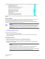
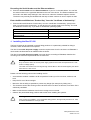
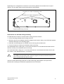
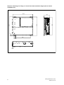
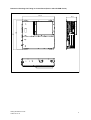
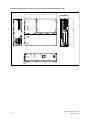
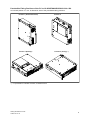
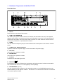
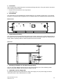
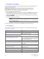
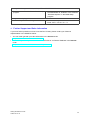
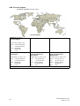
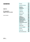
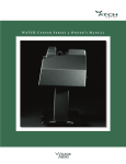
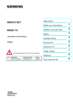
SIMATIC
Box PC 620
Getting Started
Edition 04/2003
First Steps in Commissioning
Valid for devices with the order number 6ES7647-5...
Safety guidelines
This Getting Started contains notices intended to ensure personal safety, as well as to protect the products and
connected equipment against damage. These notices are highlighted by the symbols shown below and graded
according to severity by the following texts:
!
!
!
Danger
indicates that death, severe personal injury or substantial property damage will result if proper precautions are not
taken.
Warning
indicates that death, severe personal injury or substantial property damage can result if proper precautions are not
taken.
Caution
indicates that minor personal injury can result if proper precautions are not taken.
Caution
indicates that property damage can result if proper precautions are not taken.
Notice
draws your attention to particularly important information on the product, handling the product, or to a particular
part of the documentation.
Qualified Personnel
Repair, maintenance and servicing of device only to be carried out by qualified personnel. Qualified persons are
defined as persons who are authorized to commission, to ground and to tag circuits, equipment, and systems in
accordance with established safety practices and standards.
Correct Usage
Note the following:
!
Warning
This device and its components may only be used for the applications described in the catalog or the technical
description, and only in connection with devices or components from other manufacturers which have been
approved or recommended by Siemens.
This product can only function correctly and safely if it is transported, stored, set up, and installed correctly, and
operated and maintained as recommended.
Trademarks
SIMATICR, SIMATIC HMIR and SIMATIC NETR are registered trademarks of Siemens AG.
Third parties using for their own purposes any other names in this document which refer to trademarks might infringe upon the rights of the trademark owners.
Copyright E Siemens AG 2002-2003 All rights reserved
Disclaim of Liability
The reproduction, transmission or use of this document or its
contents is not permitted without express written authority.
Offenders will be liable for damages. All rights, including rights
created by patent grant or registration of a utility model or design, are
reserved.
We have checked the contents of this manual for agreement with the
hardware and software described. Since deviations cannot be precluded entirely, we cannot guarantee full agreement. However, the
data in this manual are reviewed regularly and any necessary corrections included in subsequent editions. Suggestions for improvement are welcomed.
Siemens AG
Organization Group Automation and Drives
Division Systems Engineering
Postfach 2355, D- 90766 Fuerth
Siemens Aktiengesellschaft
E Siemens AG 2002-2003
Technical data subject to change.
A5E00131477Ć03
This Getting Started offers you step by step instructions on how to install and start the Box PC 620.
Unpacking the Box PC 620 . . . . . . . . . . . . . . . . . . . . . . . . . . . . . . . . . . . . . . . . . . . . 3
Installing the Box PC 620 . . . . . . . . . . . . . . . . . . . . . . . . . . . . . . . . . . . . . . . . . . . . . 4
Hardware Components of the Box PC 620 . . . . . . . . . . . . . . . . . . . . . . . . . . . . . 11
Connection to the Power Supply Unit . . . . . . . . . . . . . . . . . . . . . . . . . . . . . . . . . . 14
Powering Up the Box PC 620 . . . . . . . . . . . . . . . . . . . . . . . . . . . . . . . . . . . . . . . . . 15
Switching Off the Box PC 620 . . . . . . . . . . . . . . . . . . . . . . . . . . . . . . . . . . . . . . . . 15
Reinstallation of the Software . . . . . . . . . . . . . . . . . . . . . . . . . . . . . . . . . . . . . . . . . 16
Error Diagnosis . . . . . . . . . . . . . . . . . . . . . . . . . . . . . . . . . . . . . . . . . . . . . . . . . . . . . 16
Further Support and Sales Information . . . . . . . . . . . . . . . . . . . . . . . . . . . . . . . . . 17
Certificates, Directives and Declarations . . . . . . . . . . . . . . . . . . . . . . . . . . . . . . . 19
The references to the manual are intended to give you an initial overview of the information in the
manual.
Electronic Manual
You can find the electronic manual on the included CD “Documentation and Drivers”. To read or to
print out the manual start the Start program and follow the instructions on the screen.
The manual offers information on many useful topics, for example, optional hardware-expansion,
modification of the device configuration and technical data.
!
Warning
To avoid damage to assets and for the sake of your own personal safety, please take note of the
information on safety in this user guide and in the electronic manual. These notes are highlighted
with triangular warning signs. They are presented in different ways and in accordance with the
degree of risk.
+ Unpacking the Box PC 620
Unpack your Box PC 620 as follows:
1. Remove the Box PC 620 from the packaging.
2. Do not throw the original packing away. Keep it in case you have to transport the unit again
sometime in the future.
Checking the Contents
3. Check with the delivery note to make sure no components are missing.
4. Check the packing and its contents for any shipping or transport damage.
5. Please inform your local dealer of any shipping or transport damages and of outstanding items
indicated on the packing list.
Caution
Risk of mechanical damage of your device!
When transporting your PC in cold weather, when it may be exposed to extreme variations in
temperature, make sure that no moisture or condensation can form on or in the unit.
The unit should be allowed to reach room temperature slowly before it is started up. If condensation
has formed, the unit should be left for about 12 hours before being switched on.
Getting Started Box PC 620
A5E00131477-03
3
Recording the Serial Number and the Ethernet address
6. Enter the serial number and the Ethernet address of your PC in the table below. You can find
the serial number on the type label attached to the rear of the device. The Ethernet address can
be found in the BIOS setup settings in the main menu under the ’Hardware Options’ function.
The device can precisely be identified with the help of these numbers in case of repairs or theft.
Enter the Microsoft Windows “Product Key” from the “Certificate of Authenticity”
7. Enter the Microsoft Windows “Product Key” from the “Certificate of Authenticity” (COA) in the
table. You will find the “Product Key” on the device on the power supply unit covering. You need
the Windows “Product Key” if you want to reinstall the operating system.
Serial number
SVP...
Order No.
6ES...
Microsoft Windows Product Key
Ethernet Address
+ Installing the Box PC 620
The Box PC 620 can be operated in several fitting positions. It is particularly suitable for fitting in
consoles, switch boards and control panels.
The Box PC 620 with AC power supply meets the requirements for a fire enclosure to EN60950. it
can therefore be fitted without an additional fire enclosure.
The Box PC 620 with DC power supply is an open device according to EN60950; therefore the
mounting must meet the requirements of a fire enclosure.
!
Warning
Only connect the device to 24V DC power supply systems which meet the requirements of a safe
extra-low voltage (SELV).
The cable cross section has to be large enough that the Box PC will not be damaged by the cables
when there is a short circuit.
Please note the following points when installing the PC:
• Avoid extreme ambient conditions as far as possible. Protect your PC from dust, moisture, and
heat.
• Keep the PC out of direct sunlight.
• Mount the PC as safely as possible to prevent any danger (for example, by falling over).
• The clearance around the housing must be at least 100 mm at the front and rear, so that the PC is
sufficiently ventilated.
• Make certain that the ventilation slots for the housing are not covered.
• Observe the permissible fitting positions without fail when installing the systems.
!
4
Warning
If the systems are installed in a non-permissible fitting position, the approvals pursuant to UL 1950,
UL 508 and EN60950 are no longer valid!
Getting Started Box PC 620
A5E00131477-03
Depending on the configuration of the device, two mounting brackets are included in the scope of
delivery. You can attach these to the housing with 6 screws (M3x6).
M4 thread, max. depth of engagement 5 mm
M3 thread, max. depth of engagement 5 mm
Equipotential grounding connection
Instructions for wall and ceiling mounting
To install the Box PC 620 at a concrete wall or ceiling proceed as follows:
1. Fix the mounting brackets at the housing of the PC.
2. Drill four holes of 8 mm diameter and 60 mm depth into the wall or ceiling. You will find the required
dimension drawings on the following pages.
3. Insert the concrete plugs (8 mm diameter and 50 mm long) into the drill holes.
4. Fix the PC with four screws (4 mm diameter and 50 mm long).
In a plasterboard wall or ceiling (min. 13 mm thick), drill holes of 14 mm diameter and fasten the PC
with four anchors (4 mm diameter and 50 mm long).
In a metal sheet wall or eiling (min. 2 mm thick), drill holes of 5 mm diameter and fasten the PC with
four screws (4 mm diameter and min. 15 mm long).
!
Warning
The installer must verify that the wall or ceiling can support four times the full load of the Box PC
(with mounting brackets and Add-On-Cards).
The Box PC 620 without floppy disk drive or with built-in floppy disk adapter is an open device;
therefore the mounting must meet the requirements of a fire enclosure.
Getting Started Box PC 620
A5E00131477-03
5
Dimension Drawings for Fitting in Control Panel with Installation Angle (Device without
CD ROM Drive)
297.2
266
5
301
286
80.1
232
26
11.2
6
Getting Started Box PC 620
A5E00131477-03
Dimension Drawings for Fitting in Control Panel (Device with CD ROM Drive)
99.1
286
301
297.2
Getting Started Box PC 620
A5E00131477-03
7
Dimension Drawings for Fitting in Control Panel without Installation Angle
297.2
267
80.1
11.2
8
Getting Started Box PC 620
A5E00131477-03
Permissible Fitting Positions of the PC to UL1950/EN60950/CSA22.2 No. 950
An inclined position of + 20_ is allowed in each of the permissible fitting positions.
Position 1 (Preferred Position)
Position 3 (Desktop)
Position 2
Position 4 (Ceiling) *)
*) not permissible for installed CD ROM, CD RW/DVD Drive
Getting Started Box PC 620
A5E00131477-03
9
Additional Permissible Fitting Positions of the PC to UL508/CSA 22.2 No. 142
An inclined position of $15_ is allowed in each of the permissible fitting positions. An external fire
protection housing is not necessary.
Position 5
(Fan Side Down)
*)
Position 6
(Port Side Down)
*)
*) not permissible for installed Floppy disk, CD ROM, CD RW/DVD Drive
Caution
The fitting position with the fan side down is only permitted with additional precautions because
warmed air is drawn down against the convection current, possibly causing a build-up of heat.
10
Getting Started Box PC 620
A5E00131477-03
+ Hardware Components of the Box PC 620
Port Side View
1
2
34
12
11
13
1
5
10
9
8
6
7
Mouse
PS/2 socket for connecting a PS/2 mouse.
2
COM1 V.24 /MODEM /AG
The COM 1 (TTY) port is used to connect, for example, S5 automation units (AG). The supplied
adapter can be used to convert the port into a 25-pole standard V.24 port for connecting serial port
devices such as modem, mouse or printer. Refer to Section 3.4 of the electronic manual. The line
current (TTY) interface is an optional product feature.
3
COM2
You can use the serial port 2 (V.24) to connect devices with a serial port such as modem, mouse or
printer.
4
AC/DC Power Supply Connector
Appliance socket for AC power supply or screw terminal for DC power supply.
5
PCI Slots
Internal slots for expansion modules.
6
PCI/ISA Slots
Internal slots for expansion modules.
7
PC Card
Connection for PC-Cards Type I/II/III
8
Ethernet
RJ 45-Ethernet connector. Ethernet is a local network with a bus structure for data communication
with a data transfer rate of 10 or 100 megabit per second (Mbps).
9
PROFIBUS/MPI (optional)
You can connect the Box PC 620 to an S7 automation system or to a PROFIBUS network via the
PROFIBUS/MPI port with galvanic isolation . See Section 3.7 in the electronic manual. This interface
is an optional product feature.
Getting Started Box PC 620
A5E00131477-03
11
10 USB
2 Universal Serial Bus connectors. You can use the USB port to connect external devices, for
example, CD drives, printers, modems as well as mouse and keyboard. Older operating systems do
not support this port.
11 VGA
You can connect an external VGA monitor to this connector.
12 LPT1
The parallel port connection for devices with parallel port (for example, printer)
13 Keyboard
Connection for a PS/2 keyboard.
Caution
Ensure that you use shielded cables and metal plugs to connect the peripheral units; if this is not
done, the approval for operation will be invalid! Screw down the plugs of the interface cables to the
PC housing by means of a screwdriver. You thereby improve the electrical shielding.
Drive Side View
1
2
5
1
3
4
Device Fan
Here are openings for device ventilation.
Caution
The air venting slots for outgoing air must not be obstructed. Otherwise, there is a risk of
overheating.
2
Type Label
You can find the order number and the serial number of your device on the type label.
3
Floppy disk drive
You can use 3.5 disks (with 1.44 Mbytes or 720 Kbytes of memory).
12
Getting Started Box PC 620
A5E00131477-03
4
Front Ports
The front ports are located behind the cover below the floppy disk drive. They are used for connection
of the following front elements:
• I/O port for the connection of front components
• LVDS display port
5
Reset Button
The reset button can be actuated with a pointed object (e.g. an opened up paper clip). If you actuate,
the button, a hardware reset is triggered. The PC restarts. Data loss is possible with a hardware reset.
Bottom View
1
1
Equipotential Grounding
The connection with the equipotential grounding on the system housing to the central earth terminal of
the cabinet or the unit into which the computer is fitted, ensures that faults arising from external power
supply cables, signalling cables or cables to peripheral units are diverted.
Side View
1
2
3
1
Mounting possibilities for the WinAC Backup Battery
You can mount the SIMATIC WinAC CPU41x-2PCI backup battery here. Use the battery holder
without a slot plate supplied with the WinAC module to do this.
2
Input Data of Power Supply Unit
To distinguish between both performances of the power supply unit, the power supply unit with a
105W performance been marked with Pmax=105W.
Getting Started Box PC 620
A5E00131477-03
13
3
Certificate of Authenticity with Product Key
You need the Microsoft Windows “Product Key” on the “Certificate of Authenticity” if you reinstall
software.
+ Connection to the Power Supply Unit
!
Warning
The Box PC 620 with AC power supply is equipped with a safety-tested mains cable and may only
be connected to a grounded grounding outlet.
Make sure that the socket on the device or the grounding outlet of the building installation is easily
accessible and as near as possible to the device.
The mains plug must be pulled out for complete mains separation. This point must be easily
accessible.
If the PC is installed in a cabinet, there must be a central mains disconnector.
The AC power supply unit of the Box PC 620 is designed for 120/230/240V systems. The power
supply unit has a long-range input. It is not necessary to adjust the voltage span.
If a ferrite core is contained in the scope of delivery of the device, fasten it at the power cable in the
vicinity of the connector for non-heating devices.
The DC-power supply unit of the Box PC 620 is designed for 24V systems.
!
Warning
The Box PC 620 with a DC power supply is only to be connected to a 24V DC electricity power
supply network, which fulfills the requirements of a safety extra low–voltage system (SELV).
Optionally, one of these power supplies is installed.
Equipotential Measures
Low-impedance ground connections ensure that faults arising from external power supply cables,
signalling cables or cables to peripheral units are diverted.
Therefore connect the equipotential grounding connection on the system housing to the central earth
terminal of the cabinet or the unit, into which the computer is fitted, in such a way that it has low
impedance (large surface area, large contacts). The minimum cross section should not be less than
5 mm2.
The connection is on the rear of the device and is identified by the symbol:
Before you connect the Box PC 620 to the mains, the keyboard, mouse or monitor must be
connected.
1. Insert the connector cable of these peripheral units into the corresponding sockets on the port side
of the Box PC 620.
2. Connect the device to the mains.
3. The device is now in standby mode.
14
Getting Started Box PC 620
A5E00131477-03
+ Powering Up the Box PC 620
The operating system supplied with the Box PC 620 is preinstalled on the hard disk.
When powering up the device you have to distinguish between the following:
• Initial start to set up the PCs software and a
• Complete restart after initial start.
Caution
Your PC must be switched off when inserting/removing peripheral connectors (keyboard, mouse,
printer, etc.). Otherwise, your PC could be damaged.
Initial Start of the Box PC 620
When powering up the Box PC 620 for the first time the operating system is set up automatically.
Please proceed as follows:
1. Connect the Box PC 620 to the power supply unit.
2. The PC executes a self-test. During self-test the following message appears on the screen:
Press <F2> to enter SETUP
Wait until the message disappears and follow the instructions displayed on the screen.
3. If necessary, enter your product key. The product key can be found on the device in the line
“Product Key” of the “Certificate of Authenticity”.
Notice
Never switch off your PC before software installation has been completed in order to avoid the loss
of any software components which are essential for a regular operation of the Box PC 620.
Do not change the BIOS default values, otherwise the operating system installation may not run
correctly.
Startup under Microsoft Windows
The operating system is set up once you have entered the requisite information. The Welcome to
Windows screen helps you to get familiar with the Desktop user interface.
Now the user interface is displayed following system startup every time you power up or reset the PC.
Complete Restart of the Box PC 620
Once the Box PC 620’s operating system is set up, the user interface of the operating system is
displayed following system startup every time you switch on or reset the PC.
+ Switching Off the Box PC 620
Before switching off the Box PC 620, you have to shut down the operating system to avoid loss of
data. The Box PC 620 has no mains switch and is switched off only after disconnecting it from the
mains.
Getting Started Box PC 620
A5E00131477-03
15
+ Reinstallation of the Software
In case of software errors reinstall your software using the Recovery CD, the Documentation and
Drivers CD and the Restore CD.
Recovery CD: contains the tools for installing the hard disk and the operating systems.
Documentation and Drivers CD: contains the documentation and the hardware drivers.
Restore CD: contains an Image file with the original delivery software.
To restore the delivery state, proceed as follows:
• Insert the Restore CD in the drive, restart the device and press the ESC button when the BIOS
message ”Press <F2> to enter Setup” is output. After initialization, a ”Boot Menu” is displayed.
• Select the ”CD-ROM Drive” using the cursor and in the ”CD-ROM Start Menu”, select the entry
”2. Boot from CD-ROM”
• Now follow the instructions on the screen.
Caution
All the existing data, programs, user settings and authorizations on the drives will be deleted in
the process and will thus be lost.
You will find the description of the functions in the README.TXT file on the Restore CD.
+ Error Diagnosis
The information in the following section offers support for you to diagnose and partially remedy
common errors by yourself.
Error/Cause
Remedy
Device does not run
• Connection to power supply is faulty
• Check the connection to the power supply,
mains cable, mains plug
The message: “Invalid configuration information... Press the F1 key for continue, F2 to run
Setup utility” appears on the display/monitor
• Incorrect configuration data
• Back-up battery defective or dead
• Press the ”F2” key, check the configuration
data in the BIOS Setup program, enter default
values if necessary, check error messages in
the first BIOS Setup mask
The message: ”No boot device available” appears on the display/monitor
• No bootable disk in the drive
• Wrong hard disk type entered in BIOS Setup
• Insert bootable disk.
• Use the ”Fixed Disk Function” in the Setup
program
The message: ”Keyboard stuck key failure”
• A blocked key was found during the system
self-test of the keyboard
• Check keyboard
• Restart system
The power-up of the PC is terminated after several beeps
• An error occurred during the system self-test
• Check hardware
Every time a key is pressed, a beep sounds without characters being displayed
• Keyboard buffer overflow
16
• <CTRL> <PAUSE>
Getting Started Box PC 620
A5E00131477-03
No response from ports COM1,COM2, LPT1 or PROFIBUS/MPI
• Ports are set to ”Disabled”in the BIOS Setup
program.
• Set the ports COM1,COM2, LPT1 or
PROFIBUS/MPI to ”Enabled” in the submenu
”Hardware Options” in the BIOS Setup
program.
<\> key is not displayed
• Incorrect keyboard driver being used
• Load correct keyboard driver
Enter <ALT> <9><2> for < \>
+ Further Support and Sales Information
If you have further questions on how to use the Box PC 620, please contact your Siemens
representative or the SIMATIC Hotline:
• You can obtain general up-to-date information in the Internet under
http://www.siemens.com/simatic-pc
• You can find your local partner for Automation & Drives in our Partner Database in the Internet
under
http://www.siemens.com/automation/partner
Getting Started Box PC 620
A5E00131477-03
17
A&D Technical Support
Worldwide, available 24 hours a day:
Nuernberg
Johnson City
Beijing
Technical Support
Worldwide (Nuernberg)
Technical Support
24 hours a day, 365 days a year
Phone:
+49 (0) 180 5050-222
Fax:
+49 (0) 180 5050-223
E-Mail:
adsupport@
siemens.com
GMT:
+1:00
Europe / Africa (Nuernberg)
United States (Johnson City)
Asia / Australia (Beijing)
Authorization
Technical Support and
Authorization
Technical Support and
Authorization
Local time: Mon.-Fri. 7:00 to 17:00
Local time: Mon.-Fri. 8:00 to 17:00
Local time: Mon.-Fri. 8:00 to 17:00
Phone:
Fax:
+49 (0) 180 5050–222
+49 (0) 180 5050-223
Phone:
+1 (0) 423 262 2522
Phone:
Fax:
+1 (0) 423 262 2289
Fax:
+86 10 64 74 74 74
adsupport@
siemens.com
+1:00
E-Mail:
simatic.hotline@
sea.siemens.com
E-Mail:
GMT:
–5:00
GMT:
adsupport.asia@
siemens.com
+8:00
E-Mail:
GMT:
+86 10 64 75 75 75
The languages of the SIMATIC Hotlines and the authorization hotline are generally German and English.
18
Getting Started Box PC 620
A5E00131477-03
+ Certificates, Directives and Declarations
Notes on the CE Symbol
The following applies to the SIMATIC product described in this Getting Started:
EMC Directive
Devices with a power supply performance of 85W are in accordance with the EU Directive
89/336/EEC “Electromagnetic Compatibility.” In accordance with the CE label for this product, the
following areas of application are relevant:
Application
Requirements
Emitted Interference
Immunity
Domestic, business and commercial areas, as
well as small businesses
EN 50081-1: 1992
EN 50082-1: 1992
Industrial area
EN 50081-2: 1993
EN 50082-2: 1995
The devices with AC power supply meet the norms of the the EN 61000-3-2:1995 (harmonic currents)
and EN 61000-3-3:1995 (voltage fluctuation and flicker).
The devices with power supply performance of 105W are in accordance with the EU Directive
89/336/EEC “Electromagnetic Compatibility.” In accordance with the CE label for this product, the
following area of application is relevant:
Application
Requirements
Emitted Interference
Industrial area
EN 50081-2: 1993
Immunity
EN 50082-2: 1995
The devices with AC power supply meet the norms of the the EN 61000-3-2:1995 (harmonic currents)
and EN 61000-3-3:1995 (voltage fluctuation and flicker).
Caution
This is a class A electronic device. This device may cause interference in residential areas. In this
case the user may be asked to take the necessary precautions.
Low-Voltage Directive
The devices with AC power supply complies with the requirements of the EU Directive 73/23/EEC
“Low-Voltage Directive.” Conformance with this standard has been verified according to EN 60950.
Declaration of Conformity
The EU declarations of conformity and the relevant documentation are held at the disposal of the
competent authorities at the address below:
Siemens Aktiengesellschaft
Bereich Automation and Drives
A&D AS RD4
Postfach 1963
D-92209 Amberg
Germany
Tel.: +49 9621 80 3283
Fax: +49 9621 80 3278
Getting Started Box PC 620
A5E00131477-03
19
Observing the Installation Guidelines
The installation guidelines and safety instructions specified in this documentation or the electronic
manual must be observed during startup and operation.
Connecting Peripherals
The requirements regarding noise immunity (EN50082-2:1995) are met when you connect a
peripheral suitable for an industrial environment. Peripheral devices are only be connected via
shielded cables.
Certification for the USA, Canada and Australia
One of the following markings on a device is indicative of the corresponding approval:
Underwriters Laboratories (UL) to standard UL 1950 (I.T.E)
or to UL508 (IND.CONT.EQ)
Underwriters Laboratories (UL) to Canadian standard C22.2 No. 950 (I.T.E)
or to C22.2 No. 142 (IND.CONT.EQ)
C
C
US
Underwriters Laboratories (UL) to standard UL 1950, Report E11 5352 and to Canadian
standard C 22.2 No.950 (I.T.E)
or to UL508 and C22
C22.2
2 No
No. 142 (IND
(IND.CONT.EQ)
CONT EQ)
UL Recognition Mark
Canadian Standard Association (CSA) to standard C22.2. No. 950 (LR 81690) or to
C22.2 No. 142 (LR 63533)
NRTL
20
Canadian Standard Association (CSA) to American standard UL 1950 (LR 81690) or to
UL 508 (LR 63533)
Getting Started Box PC 620
A5E00131477-03
EMC
USA
Federal Communications Commission
Radio Frequency Interference Statement
This equipment has been tested and found to comply with the limits for a Class A digital device,
pursuant to Part 15 of the FCC Rules. These limits are designed to provide reasonable protection
against harmful interference when the equipment is operated in a commercial environment. This
equipment generates, uses, and can radiate radio frequency energy and, if not installed and used
in accordance with the instruction manual, may cause harmful interference to radio
communications. Operation of this equipment in a residential area is likely to cause harmful
interference in which case the user will be required to correct the interference at his own expense.
Shielded Cables
Shielded cables must be used with this equipment to maintain compliance with FCC regulations.
Modifications
Changes or modifications not expressly approved by the manufacturer could void the user’s
authority to operate the equipment.
Conditions of Operations
This device complies with Part 15 of the FCC Rules. Operation is subject to the following two
conditions: (1) this device may not cause harmful interference, and (2) this device must accept
any interference received, including interference that may cause undesired operation.
Canada
(for devices with power supply 105W)
Canadian Notice
This Class A digital apparatus complies with Canadian ICES-003.
Avis Canadien
Cet appareil numérique de la classe A est conforme à la norme NMB-003 du Canada.
(for devices with power supply 85W)
Canadian Notice
This Class B digital apparatus complies with Canadian ICES-003.
Avis Canadien
Cet appareil numérique de la classe B est conforme à la norme NMB-003 du Canada.
Australia
This product meets the requirements of the AS/NZS 3548 Norm.
Getting Started Box PC 620
A5E00131477-03
21
Siemens AG
Organization Group Automation and Drives
22 Systems Engineering
Division
Postfach 2355, DĆ90766 Fuerth
Siemens Aktiengesellschaft
E Siemens AG 2002Ć2003
Subject to technical change.
A5E00131477Ć03
Printed in the Fed. Rep. of Germany
Getting Started Box PC 620
A5E00131477-03